

Polycom Collaboration Server (RMX) 1500, Collaboration Server (RMX)2000, RealPresence RMX 4000, RealPresence RMX 1500, RealPresence RMX 2000 Deployment Manual
Page 1

[Type the document title]
Polycom Document Title 1
Polycom® RealPresence® Collaboration Server
Version 8.1 | July 2013 | DOC2714A
(RMX) 1500/2000/4000 Deployment Guide
for Maximum Security Environments
Page 2

Trademark Information
POLYCOM® and the names and marks associated with Polycom's products are trademarks and/or service
marks of Polycom, Inc., and are registered and/or common law marks in the United States and various other
countries.
All other trademarks are the property of their respective owners.
Patent Information
The accompanying product may be protected by one or more U.S. and foreign patents and/or pending patent
applications held by Polycom, Inc.
This document provides the latest information for security-conscious users running Version 8.1.4.J software.
The information in this document is not intended to imply that DoD or DISA certifies Polycom RMX systems.
This software has not achieved UC APL certification.
© 2013 Polycom, Inc. All rights reserved.
Polycom, Inc.
6001 America Center Drive
San Jose CA 95002
USA
No part of this document may be reproduced or transmitted in any form or by any means, electronic or
mechanical, for any purpose, without the express written permission of Polycom, Inc. Under the law,
reproducing includes translating into another language or format.
As between the parties, Polycom, Inc., retains title to and ownership of all proprietary rights with respect to
the software contained within its products. The software is protected by United States copyright laws and
international treaty provision. Therefore, you must treat the software like any other copyrighted material (e.g.,
a book or sound recording).
Every effort has been made to ensure that the information in this manual is accurate. Polycom, Inc., is not
responsible for printing or clerical errors. Information in this document is subject to change without notice.
Page 3

Table of Contents
First Time Installation and Configuration . . . . . . . . . . . . . . . . . . . . . . . . . . . . 1-1
Workstation Requirements ................................................................................................... 1-1
Required IT Infrastructure ....................................................................................................1-1
DNS ..................................................................................................................................1-2
NTP Servers .....................................................................................................................1-2
Certificate Authority Server .......................................................................................... 1-2
RMX Hardware ....................................................................................................................... 1-3
Installation and Configuration .............................................................................................1-3
Procedure 1: Hardware Installation and Setup .................................................................. 1-4
Installing the Telescopic Rail Runners on the Rack ................................................... 1-5
Telescopic Rail Runners Accessory Kit ...............................................................1-5
Telescopic Rail Runner Assembly ........................................................................ 1-6
Installing the RMX 1500 .................................................................................................1-8
Optional. Installing the RTM ISDN 1500 Card on the RMX 1500 ...................1-8
Mounting the Collaboration Server 1500 in a Rack ...........................................1-9
Connecting Cables to the RMX 1500 ..................................................................1-11
Installing the RMX 2000 ...............................................................................................1-12
Optional. Installing the RTM ISDN Card on the RMX 2000 .......................... 1-12
Mounting the Collaboration Server 2000 in a Rack .........................................1-12
Connecting Cables to the RMX 2000 ..................................................................1-13
Installing the RMX 4000 ...............................................................................................1-15
Optional. Installing the RTM ISDN Card on the RMX 4000 .......................... 1-15
Mounting the Collaboration Server 4000 in a Rack .........................................1-16
Connecting the RMX 4000 to the Power Sources .............................................1-17
Connecting Cables to the RMX 4000 ..................................................................1-19
Procedure 2: Gather Network Equipment and Address Information .......................... 1-20
IP Services ......................................................................................................................1-20
Management Network .........................................................................................1-20
Signaling Network ...............................................................................................1-20
IP Network Services Required Information .....................................................1-20
ISDN/PSTN Services ...................................................................................................1-21
Procedure 3: First Entry Configuration .............................................................................1-21
Product Registration ....................................................................................................1-22
Obtaining the Activation Key ............................................................................. 1-22
First-time Power-up and Connection to MCU ......................................................... 1-22
Configuring the workstation for direct connection .........................................1-22
Connecting to the Default Management Network ..........................................1-24
Product Activation ............................................................................................... 1-26
Modifying the Signaling Network Service and ISDN/PSTN Network Service
Settings ...........................................................................................................................1-28
Fast Configuration Wizard .................................................................................. 1-28
Procedure 4: Enable Ultra Secure Mode ...........................................................................1-45
Connecting to the RMX .......................................................................................1-46
Table of Contents
Polycom, Inc 1
Page 4

RealPresence Collaboration Server (RMX) 1500/2000/4000 Deployment Guide for Maximum Security Environments
Procedure 5: Enable Secured Communication .................................................................1-47
Enabling Secure Mode .................................................................................................1-48
Purchasing a Certificate .......................................................................................1-48
Installing the Certificates .............................................................................................1-50
Installing the RMX Certificate .............................................................................1-50
Installing the CA Certificate(s) ............................................................................1-51
Certificate Revocation ..........................................................................................1-53
Installing the CRL .................................................................................................1-54
Switching to Secure Communication Mode .............................................................1-55
Procedure 6: Set System Configuration Flags ...................................................................1-56
Modifying Flag Values .................................................................................................1-58
Procedure 7: Enable Network Separation (RMX 2000) ...................................................1-59
Enabling Network Separation .............................................................................1-60
Procedure 8: Configure 802.1x Authentication ................................................................1-61
Procedure 9: Configure IVR Settings .................................................................................1-62
Procedure 10: Optional. Modify Default Login and Main Screen Banner Text ...........1-64
Login Screen Banner .....................................................................................................1-64
Main Screen Banner ......................................................................................................1-65
Customizing Login and Main Screen Banners .........................................................1-66
Procedure 11: Rename the Default POLYCOM User ......................................................1-67
Procedure 12: Disable Inline AutoComplete Option in Web Browser .........................1-67
Procedure 13: Configure White List Access ......................................................................1-68
Basic Operation . . . . . . . . . . . . . . . . . . . . . . . . . . . . . . . . . . . . . . . . . . . . . . . . .2-1
Starting the RMX Web Client ................................................................................................2-1
RMX Web Client Screen Components .................................................................................2-3
Viewing and System Functionality Permissions ................................................2-4
Conferences List ..............................................................................................................2-4
List Pane ...........................................................................................................................2-5
RMX Management ..........................................................................................................2-5
Status Bar ..........................................................................................................................2-5
System Alerts ...........................................................................................................2-6
Participant Alerts ....................................................................................................2-6
Port Usage Gauges ..................................................................................................2-6
MCU State ................................................................................................................2-7
Address Book ..................................................................................................................2-7
Displaying and Hiding the Address Book ..........................................................2-8
Conference Templates ....................................................................................................2-8
Displaying and Hiding Conference Templates ..................................................2-9
Customizing the Main Screen .....................................................................................2-10
Customizing the RMX Management Pane ........................................................2-11
Starting a Conference ...........................................................................................................2-12
Starting a Conference from the Conferences Pane ...................................................2-12
General Tab ............................................................................................................2-14
Participants Tab ....................................................................................................2-16
Information Tab ....................................................................................................2-19
Starting a Reservation ..................................................................................................2-20
Starting an Ongoing Conference From a Template .................................................2-21
2 Polycom, Inc
Page 5

Table of Contents
Connecting to a Conference ................................................................................................2-22
Direct Dial-in .................................................................................................................2-22
H.323 Participants .................................................................................................2-23
Entry Queue Access .....................................................................................................2-24
H.323 Participants .................................................................................................2-24
ISDN and PSTN Participants .............................................................................. 2-25
Dial-out Participants .................................................................................................... 2-25
Text Indication in the Video Layout ..................................................................................2-25
Endpoint Names ................................................................................................... 2-25
Text Indication ...................................................................................................... 2-27
Transparent Endpoint Names ............................................................................2-27
Monitoring Ongoing Conferences .....................................................................................2-28
Operation Selection ......................................................................................................2-28
Multi Selection ......................................................................................................2-28
Conference Level Monitoring .....................................................................................2-29
Participant Level Monitoring ...................................................................................... 2-31
Participant Connection Monitoring ................................................................... 2-31
Operations Performed During On Going Conferences .................................................. 2-33
Conference Level operations ......................................................................................2-33
Changing the Duration of a Conference ...........................................................2-33
Adding Participants from the Address Book ...................................................2-35
Saving an Ongoing Conference as a Template ................................................. 2-35
Changing the Video Layout of a Conference ................................................... 2-36
Video Forcing ........................................................................................................ 2-37
Enabling and Disabling Video Clarity™ ........................................................... 2-38
Participant Level Operations ...................................................................................... 2-39
Personal Layout Control with the RMX Web Client .......................................2-40
Personal Layout Selection with Click&View ....................................................2-42
Conference Control Using DTMF Codes .................................................................. 2-43
Installing RMX Manager for Secure Communication Mode . . . . . . . . . . . . . . 3-1
Procedure 1 .............................................................................................................. 3-1
Procedure 2 .............................................................................................................. 3-2
Set the RMX to Non Secure Communication Mode .......................................... 3-2
Create/Purchase a Certificate ...............................................................................3-3
Install the RMX Certificate ....................................................................................3-6
Set the RMX to Secure Communication Mode ...................................................3-6
Reset the RMX .........................................................................................................3-7
Install the RMX Manager: ......................................................................................3-7
Using an Internal Certificate Authority ......................................................................3-9
Restoring the RMX Using the USB Port . . . . . . . . . . . . . . . . . . . . . . . . . . . . . 4-1
Operations Performed Using a USB Device .......................................................................4-2
Restore to Default (Normal) Security Mode ...............................................................4-2
Comprehensive Restore to Factory Defaults ..............................................................4-3
Performing a Comprehensive Restore to Factory Defaults ..............................4-3
Emergency CRL (Certificate Revocation List) Update ............................................4-10
Deploying a Polycom RMX™ Serial Gateway S4GW . . . . . . . . . . . . . . . . . . . 5-1
Network Infrastructure .........................................................................................................5-1
Polycom, Inc 3
Page 6

RealPresence Collaboration Server (RMX) 1500/2000/4000 Deployment Guide for Maximum Security Environments
Single Serial Gateway .....................................................................................................5-1
Multiple Serial Gateways ...............................................................................................5-2
Guidelines ................................................................................................................5-2
Configuring the RMX - Serial Gateway Connection .........................................................5-4
Procedure 1: Initial Setup of the Serial Gateway ........................................................5-4
Procedure 2: Configure a Network Service on the RMX for each of the Serial
Gateways and Connect the Serial Gateways to the RMX .........................................5-8
Management of Serial Gateways ........................................................................5-12
Testing ............................................................................................................................5-13
Dialing to the RMX from an ISDN Endpoint ....................................................5-13
Dialing to an ISDN Endpoint from the RMX ....................................................5-13
Serial Gateway S4GW - Maximum Security Mode ..........................................................5-13
Advanced Commands .................................................................................................5-16
Troubleshooting . . . . . . . . . . . . . . . . . . . . . . . . . . . . . . . . . . . . . . . . . . . . . . . . .6-1
Collaboration Server Web Client Installation - Troubleshooting Instructions ..............6-1
Procedure 1: Ending all Internet Explorer Sessions ...................................................6-2
Procedure 2: Deleting the Temporary Internet Files, RMX Cookie and
RMX Object ......................................................................................................................6-2
Deleting the Temporary Internet Files .................................................................6-3
Deleting the RMX/Collaboration Server Cookie ...............................................6-5
Deleting the RMX/Collaboration Server ActiveX Object .................................6-6
Procedure 3: Managing Add-ons Collisions ...............................................................6-7
Procedure 4: Add the Collaboration Server to the Internet Explorer Trusted Sites
List .....................................................................................................................................6-8
Procedure 5: Browser Hosting Controls (Optional) .................................................6-10
4 Polycom, Inc
Page 7

First Time Installation and
Configuration
Do not insert a USB device into the RMX’s USB port unless it is your intention to disable Secured
Mode or perform a Comprehensive Restore to Factory Defaults.
Workstation Requirements
The RMX Web Client and RMX Manager applications can be installed in an environment that
meets the following requirements:
• Minimum Hardware – Intel® Pentium® III, 1 GHz or higher,
1024 MB RAM, 500 MB free disk space.
• Workstation Operating System – Microsoft® Windows® XP, Vista®.
• Network Card – 10/100 Mbps.
• Web Browser – Microsoft® Internet Explorer® Version 6 or higher.
• FIPS – Is always enabled in Ultra Secure Mode, and when ClickOnce is used to install
RMX Manager, the workstation must have one of the following installed:
— .NET Framework 3.5 or a later version of the .NET Framework.
— .NET Framework 2.0 plus Service Pack 1 or later.
.Net Framework 2.0 is required and installed automatically.
The RMX must be installed on the intranet or added to the trusted sites list. In both cases, the
ActiveX control will install properly.
1
Management of the RMX using the RMX Web Client requires the installation of ActiveX. In
deployments were ActiveX is prohibited, administrators must use the RMX Manger.
For users deploying a RMX Serial Gateway S4GW, the VIEW_RVGW_ACTIVEX System Flag can
be added and its value modified to determine if ActiveX controls are used to display the RMX Serial
Gateway S4GW web site. If the flag value is set to NO (default) an external Internet Explorer
browser is launched to display the RMX Serial Gateway S4GW web site.
For more information see the RealPresence Collaboration Server (RMX) 1500/2000/4000
Administrator’s Guide for Maximum Security Environments "ActiveX Bypass” on page 17-89.
Required IT Infrastructure
The following IT infrastructure components are required to secure the RMX conferencing
(audio and video) solution.
Polycom, Inc. 1-1
Page 8

RealPresence Collaboration Server (RMX) 1500/2000/4000 Deployment Guide for Maximum Security Environments
•External Domain Name Server (DNS)
• Network Time Protocol (NTP) server
• Certificate Authority server.
• Certificate Revocation List (CRL) distribution point for each Certificate Authority (CA) used
in the configuration
DNS
All systems that are part of the secure solution, whether IT infrastructure or Polycom devices,
must be configured with the capability to resolve all other Polycom and other IT
infrastructure device Host Names on the network. This includes all workstations used to
access the RMX Management Network such as the RMX Web Client or RMX Manager.
The easiest way to do this is to use a DNS server to ensure that each device in the
deployment can be identified by a Host Name or Fully Qualified Domain Name (FQDN).
• Devices must have FQDNs in order to use security certificates.
• In dual stack network configurations that support both IPv4 and IPv6, both IP
addresses must be included in the DNS configuration.
• When connecting to devices within the IT infrastructure from Polycom devices, the
FQDN of the respective machines should be used.
NTP Servers
In order to meet Maximum Security requirements, a secure audio and video conferencing
environment must include at least two NTP servers. Security certificates are not required for
NTP servers.
The RealPresence Server will not use a time source such as a Windows-based, W32Time service
(SNTP) time service. Only full-featured (Stratum 16 or below) NTP Servers are considered
sufficiently reliable for high-accuracy timing environments.
Certificate Authority Server
A certificate authority (CA) server is used to issue and manage security credentials. A CA
server is an integral part of a (Public Key Infrastructure) PKI security system and is a required
component of a Maximum Security Environment.
• Polycom products must be able to resolve the CA server using its Fully Qualified Domain
Name (FQDN).
• With the exception of the NTP servers, all networked components within the Maximum
Security Environment must have a valid certificate or certificate chain. A Certificate
Revocation policy and a Certificate Revocation method for all networked components
must also be established.
• Certificates issued for Polycom devices within a Maximum Security Environment must
meet the specific requirements as described in Polycom® RMX® 1500/2000/4000
Administrator’s Guide for Maximum Security Environments "Certificate Configuration and
Management” on page E-1.
• For certificate management, networked components within the Maximum Security
Environment can use either an Online Certificate Status Protocol (OCSP) responder or
Certificate Revocation Lists (CRLs). The RMX currently supports only CRLs. For more
1-2 Polycom, Inc.
Page 9

information see Polycom® RMX® 1500/2000/4000 Administrator’s Guide for Maximum
Security Environments "Certificate Configuration and Management” on page E-1.
RMX Hardware
Version N.0 requires that MPM+ cards are installed in the RMX.
Installation and Configuration
First Time Installation and Configuration of the Collaboration Server 1500/2000/4000 consists
of the following procedures:
1 Hardware Installation and Setup
— Mount the RMX in a rack.
— Connect the necessary cables.
2 Gather Network Equipment and Address Information
— Get the information needed for integrating the RMX into the local (Signaling and
Management) networks.
3 First Entry Configuration
— Register the RMX.
— Power up the RMX.
— Modify the Default Management Network.
— Configure the Signaling Network Service.
— Configure the ISDN/PSTN Network Service.
4 Enable Ultra Secure Mode
5 Enable Secured Communication
— Purchase and Install the SSL/TLS certificate
— Modify the Management Network settings
— Create/Modify the relevant System Flags
6 Set System Configuration Flags
7 Enable Network Separation (RMX 2000)
8 Configure 802.1x Authentication
9 Configure IVR Settings
10 Modify Default Login Banner Text (if required)
11 Rename the default POLYCOM user
12 Disable Inline AutoComplete Option in Web Browser
13 Configure White List Access
Chapter 1-First Time Installation and Configuration
Polycom, Inc. 1-3
Page 10

RealPresence Collaboration Server (RMX) 1500/2000/4000 Deployment Guide for Maximum Security Environments
Procedure 1: Hardware Installation and Setup
In a well ventilated area, mount the RMX 1500/RMX 2000/RMX4000 unit in a 19” rack. It is
important to adhere to the Site Requirements as described in the RMX 2000/4000 Hardware
Guides, "Site Requirements” on page 1-3.
To maximize conferencing performance, especially in high bit rate call environments, a 1Gb
connection is recommended for all RMX types.
The following procedures have to be performed to install the RMX System in your site:
• Installing the RMX in a rack or as a standalone. When installing the RMX unit on a rack,
this process is done in two stages:
— Installing the telescopic rail runners on the rack. This stage is identical to all RMX
system types.
— Mounting the RMX on the rack using the previously installed rail runners
• Connecting the RMX to the power source
• Connecting the network (LAN and ISDN) cables to the RMX.
1-4 Polycom, Inc.
Page 11

Installing the Telescopic Rail Runners on the Rack
Telescopic Rail Runners Accessory Kit
Before installing the telescopic rail runners in the rack, make sure that the kit has the
following parts:
Table 1-1 Rail Runners Kit Contents
Chapter 1-First Time Installation and Configuration
Part/Kit no. Item
ASY2716A-L0
Rail runner Left rail runner (two
types available: item (a)
with or (b) without rail
runner clip
Note: The rail runner
clip is designed to
attach and clip onto the
chassis runner frame.
Right rail runner (two
types available: with or
without rail runner clip)
Note: The rail runner
clip is designed to
attach and clip onto the
chassis runner frame.
Item
no. Item Sample
1(a) (b)
Note: rail runner end views
2 See Figure 1-1 1
Item
Quantity
1
Rack spacer
assembly kit
Rail runner assembly
kit
Polycom, Inc. 1-5
Rack spacer 3 Front & Rear 4
Flat head screw M5*10mm
Flat head screw M3*8mm
Flat washer M3 6 4
Nut spring M3 7 4
48
54
Page 12

RealPresence Collaboration Server (RMX) 1500/2000/4000 Deployment Guide for Maximum Security Environments
LEFT RAIL
RIGHT RAIL
Table 1-1 Rail Runners Kit Contents
Item
Part/Kit no. Item
RMX chassis
assembly kit
Pan head screw M5*12mm
Flat washer M5 9 2
no.
82
Item Sample
Telescopic Rail Runner Assembly
Rack Rail Runners require a minimum of 48cm and a maximum of 80cm within the rack for
installation
1 Determine the location of the RMX on the rack:
— Allow for a 1U gap above and below the system for ventilation.
— Use the Rack Spacer (item no. 3) to predetermine its position on the rack post,
making sure that square studs of the spacer fit into the rack post’s square/rounded
mounting holes. Mark the spacer’s location on the rack post. Repeat this process for
the 3 remaining vertical posts ensuring that the system can be horizontally seated.
Item
Quantity
Figure 1-1 Front view of RMX Rail Runner Assembly
1-6 Polycom, Inc.
Page 13

Chapter 1-First Time Installation and Configuration
2 Position the Rack Spacer (item no. 3) onto the marked rack post together with left rack
rail runner (item no. 1 which is labeled LEFT) and fasten the flat head screws 3*10mm
(item no. 4) as shown in the following figure:
Figure 1-2 Detail of Front Rack Spacer Assembly (left rail runner is shown here) for all RMX
types
• On the RMX1500/4000 the center hole on the Rack Spacer must be left clear as it is required for
fixing the RMX to the rack post. See Figure 1-2.
• On the RealPresence Collaboration Server (RMX) 2000 the top hole on the Rack Spacer must
be left clear as it is required for fixing the RMX to the rack post. See Figure 1-2.
3 Adjust the telescopic rack rail runner to the rack opening and mount it onto the marked
position of the rear post as described in step 2.
Figure 1-3 Detail of Rear RealPresence Collaboration Server (RMX) 1500/2000/4000 Rack
Spacer Assembly
Polycom, Inc. 1-7
Page 14

RealPresence Collaboration Server (RMX) 1500/2000/4000 Deployment Guide for Maximum Security Environments
4 Repeat steps 2 and 3 for the right rack rail runner.
5 Install the flat head screw (item 5), flat washer (item 6) and nut spring
(item 7) in the middle of the telescopic rack rail runner for added stability as
shown in Figure 1-4.
Figure 1-4 Detail of Left Rail Runner (front internal view)
The number of screws to install depends on the rack width.
6 Repeat step 5 for the right rack rail runner.
Installing the RMX 1500
For detailed instructions, precautions and requirements for installing the RMX 1500 refer to the
Polycom RMX 1500 Hardware Guide.
The following procedures have to be performed to install the RMX 1500 in your site:
• Optional. Installing the RTM ISDN card on the RMX (Optional)
• Installing the RMX in a rack or as a standalone
• Connecting the RMX to the power source
• Connecting the network (LAN, IP and ISDN) cables to the RMX.
Optional. Installing the RTM ISDN 1500 Card on the RMX 1500
If the ISDN option was purchased with your RMX, the ISDN card is shipped separately and
must be manually installed into the rear of the RMX 1500. It is recommended to install the
ISDN card before the RMX 1500 is placed in a rack.
Removing the blank cover from the rear of the RMX 1500
1 Ensure that the power switch on the Collaboration Server is turned OFF (O).
1-8 Polycom, Inc.
Page 15

Chapter 1-First Time Installation and Configuration
2 Remove the cover by unscrewing the captive screws that fasten the card to the MCU.
3 Slide out the cover.
Installing the RTM ISDN 1500 Card
1 Slide in the RTM ISDN 1500 card.
2 Insert the card into the slot and tighten the captive screws on each side of the rear panel
of the card, securing the RTM ISDN card to Collaboration Server.
A Software License is included with the ISDN card. This license must be registered as part of
the Product Registration and Product Activation process.
Mounting the Collaboration Server 1500 in a Rack
There are two methods for installing the Collaboration Server in a 19” rack:
• Using the rack rail runners on the RMX 1500
— Install the telescopic rail runners, as described in "Installing the Telescopic Rail
Runners on the Rack” on page 1-5.
— Mount the Collaboration Server 1500 on top of the rail runners.
Polycom, Inc. 1-9
Page 16

RealPresence Collaboration Server (RMX) 1500/2000/4000 Deployment Guide for Maximum Security Environments
— Fasten the Collaboration Server to the rack spacers using the flat head screw
(item 8) with flat washer (item 9) through the two holes in the Collaboration
Server’s front mounting brackets.
Refer to Figure 1-2, "Detail of Front Rack Spacer Assembly (left rail runner is shown here) for all
RMX types” on page 1-7 for installation instructions.
• Using a shelf
— Install the shelf, supplied by the rack manufacturer, in the rack.
— Mount the Collaboration Server unit on the shelf.
— Fasten the Collaboration Server unit to the rack with screws through the four holes in
the Collaboration Server’s front mounting brackets.
1-10 Polycom, Inc.
Page 17

Chapter 1-First Time Installation and Configuration
E1/T1 PRI
Connection(s)
Power Cable
LAN 2 - media;
MNG - signaling;
MNG B - management & Shelf
Connecting Cables to the RMX 1500
— To connect the cables:
Before plugging network cables in, ensure sure that the network infrastructure containing all the
devices (including the RMX) has two different networks: one for Management; the other for Signaling
& Media. Separation can be achieved either by two physical networks or by two virtual networks
(VLANs).
• Connect the Media cable to LAN 2 port.
— Optional. If LAN Redundancy or Multiple Networks options are used, connect the
LAN cable to LAN 1. For more information, see RMX 1500/2000/4000
Administrator’s Guide for Maximum Security Environments, "LAN Redundancy” on
page 12-26
• Connect the Network cables to:
— the MNG (Signaling) port
— the MNGB (Management Network) port.
When an NTP Server is used for the RMX Time, the Shelf Management cable must be connected to
the shelf port.
• Optional. For ISDN/PSTN connections, connect the E1/T1 cables to their PRI (1-4)
ports.
The LAN 1*, LAN3, LAN4 and Modem ports are not be used and the plastic caps covering those
ports should not be removed.
* With Multiple network and LAN redundancy configurations, LAN 1 port is used. For more
information, see the RealPresence Collaboration Server (RMX) 1500/2000/4000 Administrators
Guide, Multiple Services and LAN Redundancy.
Polycom, Inc. 1-11
Page 18

RealPresence Collaboration Server (RMX) 1500/2000/4000 Deployment Guide for Maximum Security Environments
Installing the RMX 2000
For detailed instructions, precautions and requirements for installing the RMX 2000 refer to the
Polycom RMX 2000 Hardware Guide.
The following procedures have to be performed to install the RMX 2000 in your site:
• Optional. Installing the RTM ISDN card on the RMX (Optional)
• Installing the RMX in a rack or as a standalone
• Connecting the RMX to the power source
• Connecting the network (LAN and ISDN) cables to the RMX
Optional. Installing the RTM ISDN Card on the RMX 2000
If the ISDN option was purchased with your RMX, the ISDN card is shipped separately and
must be manually installed into the rear of the RMX 2000. It is recommended to install the
ISDN card before the RMX 2000 is placed in a rack.
Removing the blank cover from the rear of the RMX 2000
Use the following procedure to remove the blank cover:
1 Ensure that the power switch/circuit switch on the Collaboration Server is turned OFF
(O).
2 Unscrew the captive screws on the rear panel of the Collaboration Server that secure the
blank panel.
3 Use the metal ejector levers to pull the blank panel.
Installing the RTM ISDN 2000 Card
A Software License is included with the ISDN card. This license must be registered as part of
the Product Registration and Product Activation process.
Mounting the Collaboration Server 2000 in a Rack
There are two methods for installing the Collaboration Server in a 19” rack:
• Using rack rail runners on the RMX 2000:
— Install the telescopic rail runners, as described in "Installing the Telescopic Rail
Runners on the Rack” on page 1-5.
— Mount the Collaboration Server 2000 on top of the rail runners.
1-12 Polycom, Inc.
Page 19

Chapter 1-First Time Installation and Configuration
— Fasten the Collaboration Server to the rack spacers using the flat head screw
(item 8) with flat washer (item 9) through the two holes in the Collaboration
Server’s front mounting brackets.
Refer to Figure 1-2, "Detail of Front Rack Spacer Assembly (left rail runner is shown here) for all
RMX types” on page 1-7 for installation instructions.
• Using a shelf:
— Install the shelf, supplied by the rack manufacturer, in the rack.
— Mount the Collaboration Server on the shelf.
— Fasten the Collaboration Server to the rack with screws through the four holes in
the Collaboration Server’s front mounting brackets.
Connecting Cables to the RMX 2000
Do not remove the protective caps from LAN1, LAN3 and ShMG ports.
— Connect the following cables to the back panel:
Ensure sure that the network infrastructure containing all the devices (including the RMX) has two
different networks: one for Management; the other for Signaling & Media. Separation can be
achieved either by two physical networks or by two virtual networks (VLANs). These separated
networks will be used after Network Separation is performed. See "Procedure 7: Enable Network
Separation (RMX 2000)” on page 1-59.
Polycom, Inc. 1-13
Page 20

RealPresence Collaboration Server (RMX) 1500/2000/4000 Deployment Guide for Maximum Security Environments
LAN 2 Connection
Power
Cable
Off/On
switch
E1/T1 Connection
LAN 2 Connection, (optional) LAN1
•Power cable
• On the RTM IP card connect the LAN cable to LAN 2 Port.
• On the RTM LAN card connect the LAN cable to LAN 2.
— Optional. Connect the LAN cable to LAN 1.
With Multiple Networks and LAN Redundancy configurations, LAN 1 port is used.
For more information, see the RealPresence Collaboration Server (RMX) 1500/2000/
4000 Administrator’s Guide for Maximum Security Environments, "LAN Redundancy”
on page 12-26
and "Multiple Networks” on page 12-37.
• Optional. On the RTM ISDN card connect the E1/T1 Cables to PRI Ports.
1-14 Polycom, Inc.
Page 21

Installing the RMX 4000
The following procedures have to be performed to install the RMX 4000 at your site:
• Optional. Installing the RTM ISDN card on the RMX
• Mounting the RMX in a rack
• Connecting the RMX to the power source
• Connecting the network (LAN and ISDN) cables to the RMX
Optional. Installing the RTM ISDN Card on the RMX 4000
If the ISDN option was purchased with your RMX, the ISDN card is shipped separately and
must be manually installed into the rear of the RMX 2000. It is recommended to install the
ISDN card before the RMX 2000 is placed in a rack.
Removing the RTM LAN Card or the blank cover from the rear of the RMX 4000
1 Ensure that the power switch on the RealPresence Collaboration Server 1800 is turned OFF
(O).
2 Remove the RTM LAN or blank cover by unscrewing the captive screws that fasten the
card or the cover to the RMX. When removing a card, use the metal ejector levers to pull
the RTM LAN card out of its slot from the backplane.
3 Slide out the RTM LAN or RTM ISDN card.
Chapter 1-First Time Installation and Configuration
Installing the RTM ISDN 4000 Card
1 On the RTM ISDN card move the ejector levers to their fully open position.
2 Slide the new RTM ISDN card into its slot.
An RTM ISDN card must connect directly to an MPM+/MPMx card in the opposite facing front slot.
3 Push the card into the slot until the ejector levers touch the front edge of the card cage.
Push the ejector levers to their fully closed position.
4 Tighten the captive screws on each side of the rear panel of the card, securing the RTM
ISDN card to the MCU.
A Software License is included with the ISDN card. This license must be registered as part of
the Product Registration and Product Activation process.
Polycom, Inc. 1-15
Page 22

RealPresence Collaboration Server (RMX) 1500/2000/4000 Deployment Guide for Maximum Security Environments
Mounting the Collaboration Server 4000 in a Rack
Either place the RMX 4000 on a hard, flat surface such as a desktop or mount it on a 19” rack.
For a detailed description of the safety requirements and precautions and the installation of the
RMX 4000 as a standalone, or reverse mounting the RMX 4000 on a 19” rack, see the
RealPresence Collaboration Server (RMX) 4000 Hardware Guide.
To install the Collaboration Server 4000 in a 19”rack:
• Using rack rail runners on the RMX 4000
— Install the telescopic rail runners, as described in "Installing the Telescopic Rail
Runners on the Rack” on page 1-5.
— Mount the Collaboration Server 2000 on top of the rail runners.
— Fasten the Collaboration Server to the rack spacers using the flat head screw
(item 8) with flat washer (item 9) through the two holes in the Collaboration
Server’s front mounting brackets.
Refer to Figure 1-2, "Detail of Front Rack Spacer Assembly (left rail runner is shown here) for all
RMX types” on page 1-7 for installation instructions.
• Using a shelf
— Install the shelf, supplied by the rack manufacturer, in the rack.
— Mount the Collaboration Server on the shelf.
1-16 Polycom, Inc.
Page 23

Chapter 1-First Time Installation and Configuration
Power Cables
— Fasten the Collaboration Server to the rack with screws through the eight holes in
the Collaboration Server’s front mounting brackets.
Connecting the RMX 4000 to the Power Sources
The size of the protective earthing conductor & cable should be a minimum of 10AWG.
Connect the following power cables to the RMX 4000 back panel:
AC Power Supply connections:
1 Insert power cables to each of the three AC Power Entry Modules (PEMs).
DC Power Supply connections:
1 On the DC Power Rail Modules set the two circuit breakers to OFF.
Two types of circuit breakers can be installed on the DC Power Rail Module (PRM). For more
information, see the RealPresence Collaboration Server (RMX) 4000 Hardware Guide.
2 Ensure that the cables from the Main that supplies electricity to the DC power units are
OFF or disconnected.
3 Remove the transparent plastic caps on the terminal block.
Polycom, Inc. 1-17
Page 24

RealPresence Collaboration Server (RMX) 1500/2000/4000 Deployment Guide for Maximum Security Environments
ESD connector
Circuit breaker - ON
position
-48 VDC
RTN
Ground connector
Blank panel
Circuit breaker - OFF
position
4 Using the two wires of a 10 AWG cable running from the DC power distribution unit,
connect the black wire into the -48VDC terminal block and the red wire to the RTN
terminal block.
• A 10 AWG cable must be used to connect the mains with the RMX 4000 DC Power Rail Model.
• The supply wires for DC version must be terminated using quick connectors.
• Extension cords may not be used.
The center PRM slot/module is fitted with a blank panel and the slot cannot be used on a system
with DC Voltage.
5 Connect the green or green-yellow wire to the system single-point M6x15 “Ground”
bolt.
The rating of the protective earthing conductor should be a minimum of 10AWG.
If the unit is rack mounted, the single-point ground on the MCU must be connected to
the rack with a single conductor and fixed as to prevent loosening. When using bare
conductors, they must be coated with an appropriate antioxidant compound before
crimp connections are made. Tinned, solder-plated or silver plated connectors do not
have to be prepared in this manner.
6 Replace the transparent plastic caps on the terminal block.
7 Turn ON the Main that supplies power to the RMX.
8 Turn ON the circuit breaker on each of the DC Power Rail Modules.
1-18 Polycom, Inc.
Page 25

Chapter 1-First Time Installation and Configuration
LAN Connections to RTM LAN
Power Cables
Off/On
switch
E1/T1 Connection to RTM ISDN
Shelf
Management
Management
Network
Signaling
Network
Connecting Cables to the RMX 4000
— To connect the cables (AC and DC systems):
Before plugging network cables in, ensure sure that the network infrastructure containing all the
devices (including the RMX) has two different networks: one for Management; the other for Signaling
& Media. Separation can be achieved either by two physical networks or by two virtual networks
(VLANs).
• RTM-IP 4000:
— Connect the Management Network cable to LAN 2.
— Connect the Signaling cable to LAN 3.
— Connect the Shelf Management cable to LAN 6.
When an NTP Server is used for the RMX Time, the Shelf Management cable must be connected to
the shelf port.
• For each installed RTM LAN - Connect the LAN cable to LAN 2.
— Optional. Connect the LAN cable to LAN 1. With Multiple networks and LAN
redundancy configurations, LAN 1 port is used. For more information see the
Administrator’s Guide for Maximum Security Environments, "LAN Redundancy” on
page 12-26
• Optional. If RTM ISDN is installed, for each installed RTM ISDN:
— Connect the E1/T1 cables to their PRI Ports.
— Connect the LAN cable to LAN 1.
and "Multiple Networks” on page 12-37
Polycom, Inc. 1-19
Figure 1-5 RMX 4000 Rear Panel View with AC Power and Communication Cables
Page 26

RealPresence Collaboration Server (RMX) 1500/2000/4000 Deployment Guide for Maximum Security Environments
Hardware
Installation
and
Setup
Gather Network
Equipment
and
Address Info
First Entry
Configuration
Procedure 2: Gather Network Equipment and Address
Information
IP Services
The IP addresses and network parameters which enable communication between the
Collaboration Server, its management application and the conferencing devices are
contained in two IP services:
• Management Network (Control Unit)
• Signaling Network (Conferencing Service)
During the First Entry Configuration, the parameters of these two network services are
modified to comply with your local network settings.
Management Network
The Management Network enables communication between the Collaboration Server Control
Unit and the Collaboration Server Web Client and is used to manage the Collaboration Server.
The RMX is shipped with default IP addresses as listed in Table 2-1.
Signaling Network
The Signaling Network is used to configure and manage communications between the
Collaboration Server and conferencing devices.
IP Network Services Required Information
When installing an RMX unit, these default IP addresses must be modified to your local
network settings. It is therefore important to obtain the information needed to complete the
Local Network Settings section of the table from your network administrator before
powering up the RMX for the first time.
The network administrator should allocate four IP addresses in the local network for an
MCU with one MPM+ card and up to seven IP addresses for an MCU with up to four
MPM+ cards.
Table 1-2 Network Equipment and Address Information
Parameter Factory Default
Control Unit IP Address 192.168.1.254
Control Unit Subnet Mask 255.255.255.0
Default Router IP Address 192.168.1.1
Shelf Management IP Address 192.168.1.252
Signaling Host IP address –
Local Network
Settings
1-20 Polycom, Inc.
Page 27

Chapter 1-First Time Installation and Configuration
Hardware
Installation
and
Setup
Gather Network
Equipment
and
Address Info
First Entry
Configuration
Table 1-2 Network Equipment and Address Information (Continued)
Parameter Factory Default
Media Board IP address (MPM 1) –
Media Board IP address (MPM 2)
RMX 2000/4000 only
Media Board IP address (MPM 3)
RMX 4000 only
Media Board IP address (MPM 4)
RMX 4000 only
Gatekeeper IP address (optional) –
DNS IP address (optional) –
SIP Server IP address (optional) –
ISDN/PSTN Services
The ISDN/PSTN Network Service is used to define the properties of the ISDN/PSTN
switch and the ISDN lines running from the ISDN/PSTN switch to the ISDN card installed
in the Collaboration Server.
Before configuring the ISDN/PSTN Network Service, obtain the following information
from your ISDN/PSTN Service Provider:
•Switch Type
• Line Coding and Framing
•Numbering Plan
•Numbering Type
• Dial-in number range
Local Network
Settings
–
–
–
• The RMX does not support ISDN connections using restricted line rates
(56k B channels).
• If the RMX is connected to the public ISDN Network, an external CSU or
similar equipment is needed.
Procedure 3: First Entry Configuration
There are four procedures necessary for setup of the new Collaboration Server. It is important
that they are performed in the following sequence:
Polycom, Inc. 1-21
1 Product Registration.
2 Modifying the Factory Default Management Network Settings.
3 First-time Power-up and Connection to MCU.
4 Enable Network Separation (RMX 2000)
5 Modifying the Default IP and ISDN/PSTN Service settings (Fast Configuration Wizard).
Page 28

RealPresence Collaboration Server (RMX) 1500/2000/4000 Deployment Guide for Maximum Security Environments
Product Registration
Before the Collaboration Server can be used, it is necessary to register the product and obtain
an Activation Key.
During first-time power-up, the Product Activation dialog box is displayed, requesting you to
enter an Activation Key.
Obtaining the Activation Key
1 Access the Service & Support page of the Polycom website at:
http://portal.polycom.com
2 Login with your Email Address and Password or register as a new user.
3 Select Product Registration.
4 Follow the on-screen instructions for Product Registration and Product Activation. (The
RMX’s serial number is on a sticker on the back of the unit, if needed.)
5 When the Product Activation Key is displayed, write it down or copy it for later pasting
into the Activation Key field of the Product Activation dialog box.
First-time Power-up and Connection to MCU
Before powering up the RMX for the first time, it is necessary to establish a connection
between the RMX and the control workstation.
A private network is set up between the Collaboration Server and the workstation and the
Default Management Network parameters are modified using the Fast Configuration Wizard in
the Collaboration Server Web Client.
Configuring the workstation for direct connection
The following procedures show how to modify the workstation’s networking parameters
using the Windows New Connection Wizard.
For non-Windows operating systems an equivalent procedure must be performed by the
system administrator.
Before connecting directly, you must modify the IP Address, Subnet Mask and Default
Gateway settings of the workstation to be compatible with either the Collaboration Server’s
Default Management Network.
To modify the workstation’s IP addresses:
1 On the Windows Start menu, select Settings > Network Connections.
2 In the Network Connections window, double-click the Local Area Connection that has
Connected status.
1-22 Polycom, Inc.
Page 29

Chapter 1-First Time Installation and Configuration
3 In the Local Area Connection Status dialog box, click the Properties button.
4 In the Local Area Connection Properties dialog box, select Internet Protocol [TCP/IP] >
Properties.
5 In the Internet Protocol (TCP/IP) Properties dialog box, select Use the following IP
address.
Polycom, Inc. 1-23
Page 30

RealPresence Collaboration Server (RMX) 1500/2000/4000 Deployment Guide for Maximum Security Environments
6 Enter the IP address, Subnet mask and Default gateway for the workstation.
The workstation’s IP address should be in the same network neighborhood as the
RMX’s Control Unit IP address.
Example: IP address – near
192.168.1.nn
None of the reserved IP addresses listed in Ta bl e 1-3 should be used for the IP Address.
The Subnet mask and Default gateway addresses should be the same as those for the
RMX’s Default Management Network.
The addresses needed for connection to the Collaboration Server’s Default Management
Network are listed in Table 1-3.
Table 1-3 Reserved IP Addresses
Default Management Network
Network Entity
Control Unit IP Address 192.168.1.254
Control Unit Subnet Mask 255.255.255.0
Default Router IP Address 192.168.1.1
Shelf Management IP Address 192.168.1.252
Shelf Management Subnet Mask 255.255.255.0
Shelf Management Default Gateway 192.168.1.1
IP Addresses
(Factory Default)
7 Click the OK button.
Connecting to the Default Management Network
To connect directly to the RMX:
1-24 Polycom, Inc.
Page 31

Chapter 1-First Time Installation and Configuration
LAN 2 Port
RMX 4000
RMX 2000
RMX 1500
MNGB Port
8 Using a LAN cable, connect the workstation to the LAN 2 port on the RMX 2000/4000’s
back panel or the MNGB Port on the RMX 1500.
9 Connect the power cable and power the RMX On.
10 Start the RMX Web Client application on the workstation, by entering the factory setting
Management IP address in the browser’s address line and pressing Enter.
11 In the Collaboration Server Web Client Login screen, enter the default Username
(POLYCOM) and Password (POLYCOM) and click the Login button.
The Fast Configuration Wizard starts.
Both IPv4 and IPv6 are supported. For IPv6 addressing information see the RMX 1500/2000/4000
System Administrator’s Guide for Maximum Security Environments "IP Network Services” on
page 11-2.
Polycom, Inc. 1-25
Page 32

RealPresence Collaboration Server (RMX) 1500/2000/4000 Deployment Guide for Maximum Security Environments
If this is the First Time Power-up or the Default IP Service has been deleted and the RMX
has been reset, the following dialog box is displayed:
12 Enter the following parameters using the information supplied by your network
administrator:
— Control Unit IP Address
— Shelf Management IP Address
— Control Unit Subnet Mask
— Default Router IP Address
13 Click the Save & Close button.
The system prompts you to sign in with the new Control Unit IP Address.
14 Disconnect the LAN cable between the workstation and the LAN 2 port on the RMX’s
back panel.
15 Connect LAN 2 port on the RMX’s back panel to the local network using a LAN cable.
16 Enter the new Control Unit IP Address in the browser’s address line, using a workstation
on the local network, and press Enter to start the RMX Web Client application.
17 In the Collaboration Server Web Client Login screen, enter the default Username
(POLYCOM) and Password (POLYCOM) and click the Login button.
Product Activation
The RMX Web Client opens and the Product Activation dialog box appears with the serial
number filled in:
1-26 Polycom, Inc.
Page 33

Chapter 1-First Time Installation and Configuration
18 In the Activation Key field, enter or paste the Product Activation Key obtained earlier.
19 Click OK.
If you do not have an Activation Key, click Polycom Resource Center to access the
Service & Support page of the Polycom website.
For more information, see "Obtaining the Activation Key” on page 1-22.
The system prompts with a restart dialog box:
20 In the dialog box, click No.
Polycom, Inc. 1-27
Page 34

RealPresence Collaboration Server (RMX) 1500/2000/4000 Deployment Guide for Maximum Security Environments
RMX 1500
RMX 4000
RMX 2000
Modifying the Signaling Network Service and ISDN/PSTN Network Service
Settings
The Fast Configuration Wizard assists in configuring the Signaling Network Service. It starts
automatically if no Signaling Network Service is defined. This happens during First Time
Power-up, before the service has been defined or if the Signaling Service has been deleted,
followed by an RMX restart.
The IP Management Service tab in the Fast Configuration Wizard is enabled only if the factory
default Management IP addresses were not modified.
Both IPv4 and IPv6 are supported. For IPv6 addressing information see the RMX 1500/2000/4000
System Administrator’s Guide for Maximum Security Environments "IP Network Services” on
page 11 -2.
Fast Configuration Wizard
1 Enter the required IP Signaling information in the dialog box.
1-28 Polycom, Inc.
Page 35

Table 1-4 Signaling Network Service – IP Signaling
Field Description
Chapter 1-First Time Installation and Configuration
Network Service
Name
The name Default IP Service is assigned to the Signaling Network
Service by the Fast Configuration Wizard. This name can be
changed.
Note: This field is displayed in all IP Signaling dialog boxes and can
contain character sets that use Unicode encoding.
Signaling Host IP
Address
Enter the address to be used by IP endpoints when dialing into the
MCU.
Dial out calls from the Collaboration Server are initiated from this
address.
This address is used to register the Collaboration Server with a
Gatekeeper or a SIP Proxy server.
Media Card 1-4
IP Addresses
Enter the IP address(es) of the media card (s) (MPM+/MPMx 1 and
MPM+/MPMx 2-4 (if installed)) as provided by the network
administrator. Endpoints connect to conferences and transmit call
media (video, voice and content) via these addresses.
Subnet Mask Enter the subnet mask of the MCU.
Default value: 255.255.255.0.
2 Click the Next button.
3 Enter the required Routers information in the dialog box.
Table 1-5 Signaling Network Service – Routers
Field Description
Default Router
IP Address
Polycom, Inc. 1-29
Enter the IP address of the default router. The default router is used
whenever the defined static routers are not able to route packets to their
destination. The default router is also used when host access is
restricted to one default router.
Page 36

RealPresence Collaboration Server (RMX) 1500/2000/4000 Deployment Guide for Maximum Security Environments
4 Click the Next button.
5 Enter the required DNS information in the dialog box.
Table 1-6 Signaling Network Service – DNS
Field Description
MCU Host Name DNS Enter the name of the MCU on the network.
Default name is RMX
Local Domain Name Enter the name of the domain where the MCU is installed.
Primary DNS Server
IP Address
The static IP addresses of the DNS servers.
A maximum of three servers can be defined.
1-30 Polycom, Inc.
Page 37
Chapter 1-First Time Installation and Configuration
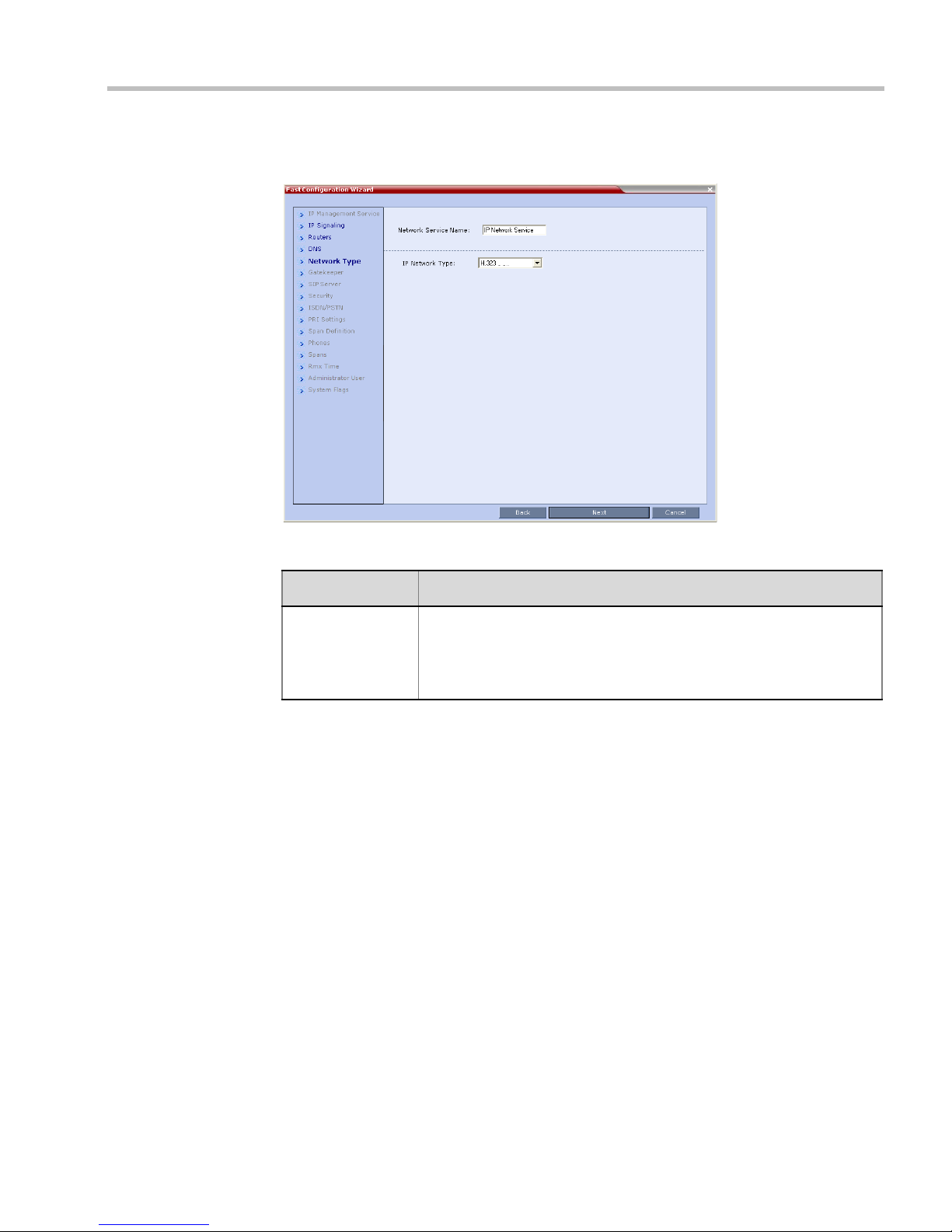
6 Click the Next button.
7 Enter the required Network Type information in the dialog box.
Table 1-7 Signaling Network Service – IP
Field Description
IP Network Type Select a Network Type:
• H.323
• SIP
• H.323&SIP
8 Click the Next button.
9 If you selected SIP only, go to Step 13.
Polycom, Inc. 1-31
Page 38

RealPresence Collaboration Server (RMX) 1500/2000/4000 Deployment Guide for Maximum Security Environments
10 Enter the required Gatekeeper information in the dialog box.
Table 1-8 Signaling Network Service – Gatekeeper Parameters
Field Description
Gatekeeper Select Specify to enable configuration of the gatekeeper IP address.
When Off is selected, all gatekeeper options are disabled.
Primary
Gatekeeper
Enter either the gatekeeper’s host name as registered in the DNS or IP
address.
IP Address or
Name
MCU Prefix in
Gatekeeper
Enter the number with which this Network Service registers with the
gatekeeper. This number is used by H.323 endpoints as the first part of their
dial-in string when dialing the MCU.
When PathNavigator or SE200 is used, this prefix automatically registers
with the gatekeeper. When another gatekeeper is used, this prefix must also
be defined in the gatekeeper.
Aliases:
Alias The alias that identifies the RMX’s Signaling Host within the network. Up to
five aliases can be defined for each RMX.
Note: When a gatekeeper is specified, at least one alias must be entered in
the table.
Additional aliases or prefixes may also be entered.
1-32 Polycom, Inc.
Page 39

Chapter 1-First Time Installation and Configuration
Table 1-8 Signaling Network Service – Gatekeeper Parameters (Continued)
Field Description
Typ e The type defines the format in which the card’s alias is sent to the
gatekeeper. Each alias can be of a different type:
• H.323 ID (alphanumeric ID)
• E.164 (digits 0-9, * and #)
• Email ID (email address format,
e.g. abc@example.com)
• Participant Number (digits 0-9, * and #)
Note: Although all types are supported, the type of alias to be used depends
on the gatekeeper’s capabilities.
11 Click the Next button.
12 If you selected H.323, click Save & Continue; otherwise click Next and go to Step 13.
If you have selected Save and Continue, the IP Network Service is created and
confirmed.
— Go to Step 17.
13 Enter the required SIP Server information in the dialog box.
Polycom, Inc. 1-33
Page 40

RealPresence Collaboration Server (RMX) 1500/2000/4000 Deployment Guide for Maximum Security Environments
Table 1-9 Fast Configuration Wizard – SIP Server
Field Description
SIP Server Select:
• Specify – to manually configure SIP servers.
• Off – if SIP servers are not present in the network.
SIP Server IP
Address
Transport Type Select the transport type and protocol that is used for signaling
Enter either the IP address of the preferred SIP server or its host
name (if a DNS server is used).
between the MCU and the SIP Server or the endpoints according to
the protocol supported by the SIP Server:
• UDP – Select this option to use UDP for signaling.
• TCP – Select this option to use TCP for signaling.
• TLS – The Signaling Host listens on secured port 5061 only and
all outgoing connections are established on secured connections.
Calls from SIP clients or servers to non secured ports are
rejected.
The following protocols are supported:
• TLS 1.0
• SSL 2.0
• SSL 3.0.
14 Click Next.
15 Enter the required Security information in the dialog box.
1-34 Polycom, Inc.
Page 41

Chapter 1-First Time Installation and Configuration
Table 1-10 Default IP Network Service – Security (SIP Digest)
Field Description
SIP Authentication Click this check box to enable SIP proxy
authentication.
Select this check box only if the authentication
is enabled on the SIP proxy, to enable the
Collaboration Server to register with the SIP
proxy. If the authentication is enabled on the
SIP proxy and disabled on the RMX, calls will
fail to connect to the conferences.
Leave this check box cleared if the
authentication option is disabled on the SIP
proxy.
User Name Enter the user name the Collaboration Server
will use to authenticate itself with the SIP
proxy. This name must be defined in the SIP
proxy.
Password Enter the password the Collaboration Server
will use to authenticate itself with the SIP
proxy. This password must be defined in the
SIP proxy.
H.323 Authentication Click this check box to enable H.323 server
authentication.
Select this check box only if the authentication
is enabled on the gatekeeper, to enable the
Collaboration Server to register with the
gatekeeper. If the authentication is enabled on
the gatekeeper and disabled on the RMX, calls
will fail to connect to the conferences.
Leave this check box cleared if the
authentication option is disabled on the
gatekeeper.
These fields can
contain up to 20
ASCII characters.
16 Click Save & Continue.
The IP Network Service is created and confirmed.
Polycom, Inc. 1-35
User Name Enter the user name the Collaboration Server
will use to authenticate itself with the
gatekeeper. This name must be defined in the
gatekeeper.
Password Enter the password the Collaboration Server
will use to authenticate itself with the
gatekeeper. This password must be defined in
the gatekeeper.
Page 42

RealPresence Collaboration Server (RMX) 1500/2000/4000 Deployment Guide for Maximum Security Environments
17 Click OK.
During the initial Collaboration Server setup, if the system detects the presence of the RTM
ISDN card, the ISDN /PSTN Network Service definition screens of the Fast Configuration
Wizard are enabled.
If there is no RTM ISDN card in the RMX or if you do not want to define an ISDN/PSTN
Network Service, go to Step 32.
• The RMX does not support ISDN connections using restricted line rates (56k B channels).
• A new ISDN/PSTN Network Service can be defined even if no RTM ISDN card is installed in
the system but only via the ISDN/PSTN Network Service ->Add New Service dialog box.
The Fast Configuration Wizard’s ISDN/PSTN configuration sequence begins with the
ISDN/PSTN dialog box:
18 Define the following parameters:
Table 1-11 Fast Configuration Wizard – ISDN Service Settings
Field Description
Network Service
Name
1-36 Polycom, Inc.
Specify the service provider’s (carrier) name or any other name you
choose, using up to 20 characters. The Network Service Name
identifies the ISDN/PSTN Service to the system.
Default name: ISDN/PSTN Service
Note: This field is displayed in all ISDN/PSTN Network Properties tabs
and can contain character sets that use Unicode encoding.
Page 43

Chapter 1-First Time Installation and Configuration
Table 1-11 Fast Configuration Wizard – ISDN Service Settings
Field Description
Span Type Select the type of spans (ISDN/PSTN) lines, supplied by the service
provider, that are connected to the RMX. Each span can be defined as
a separate Network Service, or all the spans from the same carrier can
be defined as part of the same Network Service.
Select either:
• T1 (U.S. – 23 B channels + 1 D channel)
• E1 (Europe – 30 B channels + 1 D channel)
Default: T1
Note: Only one Span Type (E1 or T1) is supported on the
Collaboration Server. If you define the first span as type E1 all other
spans that you may later define must also be of type E1.
Service Type PRI is the only supported service type. It is automatically selected.
19 Click Next.
The PRI Settings dialog box is displayed.
20 Define the following parameters:
Table 1-12 Fast Configuration Wizard – PRI Settings
Field Description
Default Num Type Select the Default Num Type from the list.
Polycom, Inc. 1-37
The Num Type defines how the system handles the dialing digits. For
example, if you type eight dialing digits, the Num Type defines whether
this number is national or international.
If the PRI lines are connected to the RMX via a network switch, the
selection of the Num Type is used to route the call to a specific PRI line.
If you want the network to interpret the dialing digits for routing the call,
select Unknown.
Default: Unknown
Note: For E1 spans, this parameter is set by the system.
Page 44

RealPresence Collaboration Server (RMX) 1500/2000/4000 Deployment Guide for Maximum Security Environments
Table 1-12 Fast Configuration Wizard – PRI Settings (Continued)
Field Description
Num Plan Select the type of signaling (Number Plan) from the list according to
information given by the service provider.
Default: ISDN
Note: For E1 spans, this parameter is set by the system.
Net Specific Select the appropriate service program if one is used by your service
provider (carrier).
Some service providers may have several service programs that can be
used.
Default: None
Dial-out Prefix Enter the prefix that the PBX requires to dial out. Leave this field blank if
a dial-out prefix is not required.
The field can contain be empty (blank) or a numeric value between 0 and
9999.
Default: Blank
21 Click Next.
The Span Definition dialog box is displayed.
22 Define the following parameters:
Table 1-13 Fast Configuration Wizard – Spans Definition
Field Description
Framing Select the Framing format used by the carrier for the network interface
1-38 Polycom, Inc.
from the list.
• For T1 spans, default is SFSF.
• For E1 spans, default is FEBE.
Page 45
Chapter 1-First Time Installation and Configuration
Table 1-13 Fast Configuration Wizard – Spans Definition
Field Description
Side Select one of the following options:
• User side (default)
• Network side
• Symmetric side
Note: If the PBX is configured on the network side, then the
Collaboration Server unit must be configured as the user side, and vice
versa, or both must be configured symmetrically.
Line Coding Select the PRI line coding method from the list.
• For T1 spans, default is B8ZS.
• For E1 spans, default is HDB3.
Switch Type Select the brand and revision level of switch equipment installed in the
service provider’s central office.
• For T1 spans, default is AT&T 4ESS.
• For E1 spans, default is EURO ISDN.
Note: For T1 configurations in Taiwan, Framing must be set to ESF and
Line Coding to B8ZS.
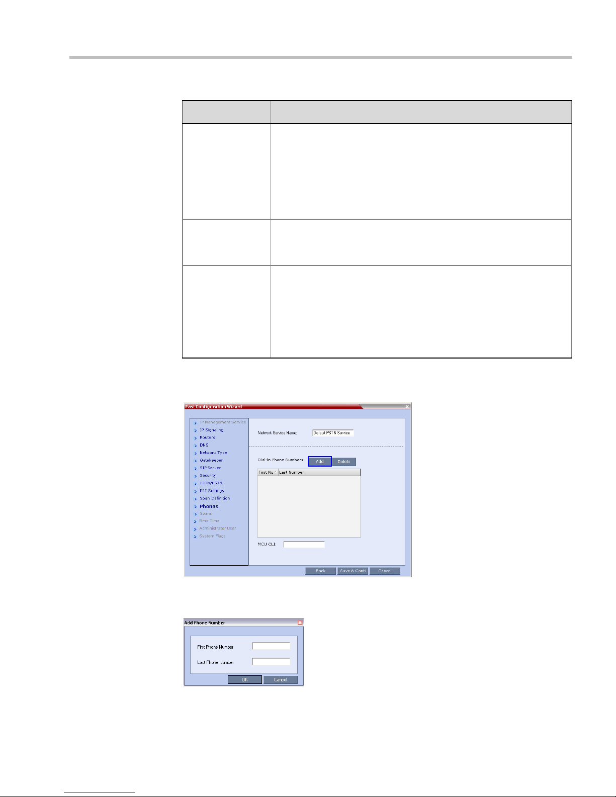
23 Click Next.
The Phones dialog box is displayed.
24 Click Add to define dial-in number ranges.
The Add Phone Number dialog box is displayed.
Polycom, Inc. 1-39
Page 46

RealPresence Collaboration Server (RMX) 1500/2000/4000 Deployment Guide for Maximum Security Environments
25 Define the following parameters:
Table 1-14 Fast Configuration Wizard – Add Phone Numbers
Field Description
First Number The first number in the phone number range.
Last Number The last number in the phone number range.
• A range must include at least two dial-in numbers.
• A range cannot exceed 1000 numbers.
26 Click OK.
The new range is added to the Dial-in Phone Numbers table.
27 Optional. Repeat steps 24 to 25 to define additional dial-in ranges.
28 In the Phones tab enter the MCU CLI (Calling Line Identification).
With dial-in connections, the MCU CLI indicates the MCU’s number dialed by the
participant. In a dial-out connection, indicates the MCU (CLI) number as seen by the
participant.
29 Click Save & Continue.
After clicking Save & Continue, you cannot use the Back button to return to previous
configuration dialog boxes.
The ISDN/PSTN Network Service is created and is added to the ISDN/PSTN Network
Services list.
If the system cannot create the ISDN/PSTN Network Service, an error message is
displayed indicating the cause and allowing you access the appropriate dialog box in
the Fast Configuration Wizard for corrective action.
30 Click OK to continue the configuration.
1-40 Polycom, Inc.
Page 47

Chapter 1-First Time Installation and Configuration
Spans
Tabl e
Attached
Spans
The Spans dialog box opens, displaying the following read-only fields:
— ID – the connector on the ISDN RTM card (PRI1 to PRI12).
— Slot – the MPM+ card that the ISDN RTM card is connected to
(MPM 1 or MPM 2).
— Service – the ISDN/PSTN Network Service to which the span is assigned.
— Clock Source – indicates if ISDN signaling synchronization is being supplied by the
Primary or Secondary clock source. The first span to synchronize becomes the
Primary clock source.
— State – the System Alert level of the span (Major, Minor). If there are no span related
alerts, this column contains no entries.
31 Click the check boxes in the Attached field to attach spans (E1 or T1 PRI lines) to the
network service named in the Network Service Name field.
The Spans Table displays the configuration of all spans and all ISDN network services in
the system.
When using the Fast Configuration Wizard during First Entry Configuration, you are
defining the first ISDN/PSTN Network Service in the system. Spans can only be attached
to this service.
Additional ISDN/PSTN Network Services can be defined by using the ISDN/PSTN
Network Services > New PSTN Service button in the RMX Web Client.
Spans can be attached to, or moved between ISDN network services by using the ISDN/
PSTN Network Services > ISDN Properties > Spans tab in the RMX Web Client.
ISDN RTM card can support either 7 E1 or 9 T1 PRI lines (E1 and T1 connections
Each
cannot be used simultaneously).
32 Click Next.
Polycom, Inc. 1-41
Page 48

RealPresence Collaboration Server (RMX) 1500/2000/4000 Deployment Guide for Maximum Security Environments
The RMX Time dialog box is displayed.
33 Set the RMX Time using one of the three available options: setting the RMX Time
manually, clicking the Retrieve Client Time button, or using the NTP Servers options.
Table 1-15 Fast Configuration Wizard - Collaboration Server Time
Field Description
GMT Date The date at Greenwich, UK.
Local Time The MCU’s local time settings, are calculated from the GMT Time
and the GMT Offset.
GMT Time Displays the MCU’s current GMT Time settings.
Option 1: Manually setting the Collaboration Server time:
• Using the Up or Down arrows alter the GMT Time and the GMT
Offset to set the Collaboration Server time.
GMT Offset The time zone difference between Greenwich and the MCU’s
physical location.
• Using the Up or Down arrows manually modify the GMT Offset
time on the Collaboration Server.
Retrieve Client Time Option 2: Automatically setting the MCU time:
• Click this button to automatically update the MCU's GMT Date,
Time and Offset to match that of the workstation.
1-42 Polycom, Inc.
Page 49

Chapter 1-First Time Installation and Configuration
Table 1-15 Fast Configuration Wizard - Collaboration Server Time (Continued)
Field Description
Use NTP Server Option 3: Setting the MCU time by synchronizing with external NTP
servers:
• Select this check box to synchronize the time with up to three
external NTP servers. Once selected, you must enter the IP
address of at least one external NTP server to implement this
mode.
• Enter the IP addresses of the required NTP servers in order of
precedence.
The Status field indicates whether registration with the NTP Server
failed or succeeded.
Notes:
• When this option is selected, the manual GMT Date and GMT
Time setting options are disabled. The GMT Offset fields are still
active.
• The RealPresence Server will not use a time source such as a
Windows-based, W32Time service (SNTP) time service. Only
full-featured (Stratum 16 or below) NTP Servers are considered
sufficiently reliable for high-accuracy timing environments.
34 Click Next.
The Administrator User dialog box is displayed.
The Administrator User Name and Password are configured in Procedure 10, after Secured
Communication has been enabled.
• If the default POLYCOM user is defined in the RMX Web Client, an active alarm is displayed
and the MCU status changes to Major until the administrator changes the default username
and password.
• System access is not permitted until the default password is changed.
35 Click Next.
The System Flags dialog box is displayed
36 Enter the required System Flags information in the dialog box.
Polycom, Inc. 1-43
Page 50

RealPresence Collaboration Server (RMX) 1500/2000/4000 Deployment Guide for Maximum Security Environments
Table 1-16 Signaling Network Service – System Flags
Flag Description / Default
Conference ID
Length (MCU)
Minimum
Conference ID
Length (User)
Maximum
Conference ID
Length (User)
MCU Display
Name
Terminate
Conference when
Chairperson Exits
Auto Extend
Conferences
The number of digits of the Conference
ID to be assigned by the MCU.
Range: 2-16 (Default: 5)
The minimum number of digits that the
user must enter when manually
Note: Selecting 2 digits limits
the number of simultaneous
ongoing conferences to 99.
assigning a numeric ID to a conference.
Range: 2-16 (Default: 4)
The maximum number of digits that the
user can enter when manually assigning
a Numeric ID to a conference.
Range: 2-16 (Default: 8)
Note: Selecting 2 digits limits
the number of simultaneous
ongoing conferences to 99.
The MCU name is displayed on the endpoint’s screen.
Default name: RMX 1500, Polycom RMX 2000 or Polycom RMX 4000.
When Yes is selected (default), the conference ends when the
chairperson exits even if
there are other participants connected.
When No is selected, the conference automatically ends at the
predefined end time, or when all the participants have disconnected from
the conference.
When Yes is selected (default), allows conferences running on the RMX
to be automatically extended as long
as there are participants connected
and there are available resources.
The maximum extension time allowed by the MCU is 30 minutes.
1-44 Polycom, Inc.
Page 51

37 Click Save & Close.
The RMX confirms successful configuration.
38 In the Success Message box, click OK.
39 In the Reset Confirmation dialog box, click Yes.
40 In the Please wait for system reset message box, click OK.
System restart may take up to five minutes.
41 Refresh the browser periodically until the Login screen is displayed.
42 When the Login screen is displayed, enter your Username and Password and click Login.
On first entry, the default Username and Password are both POLYCOM.
The system is now fully configured and if there are no System Errors, the green RDY
LED on the CNTL module on the RMX’s front panel turns ON.
Procedure 4: Enable Ultra Secure Mode
The Ultra Secure Mode is disabled by default and can be enabled by changing the value of the
ULTRA_SECURE_MODE System Flag to YES using the Setup > System Configuration
menu. After modifying the value of the ULTRA_SECURE_MODE System Flag to YES, all
RMX users are forced to change their Login passwords.
To enable Ultra Secure Mode:
1 On the RMX menu, click Setup > System Configuration.
The System Flags dialog box is displayed.
2 Locate and double-click on the ULTRA_SECURE_MODE System Flag entry.
The Update Flag Value dialog box is displayed.
3 In the New Value field, enter YES.
4 Click the OK button to close the Update Flag Value dialog box.
The user is warned that enabling Ultra Secure Mode is reversible only by performing a
Restore to Factory Defaults.
Chapter 1-First Time Installation and Configuration
5 Click the Yes button to confirm.
6 Click the Close button to close the System Flags dialog box.
7 In the Reset Confirmation dialog box, click Yes.
8 In the Please wait for system reset message box, click OK.
System restart may take up to five minutes.
Polycom, Inc. 1-45
Page 52

RealPresence Collaboration Server (RMX) 1500/2000/4000 Deployment Guide for Maximum Security Environments
Terms of Usage
Banner
Accept
Button
9 Refresh the browser periodically until the RMX Web Client – Terms of Usage screen is
displayed.
Connecting to the RMX
If the error “Browser environment error. Please close all the browser sessions” appears, close all the
browser sessions, and reconnect to the MCU. If the error message appears again, either run the
automatic troubleshooter utility or manually perform the suggested troubleshooting procedures. For
more details, see "Troubleshooting” on page B-1.
The RMX Web Client – Terms of Usage screen is displayed.
10 Click the Accept button to agree to the terms and conditions displayed in the banner.
The Login - Welcome screen is displayed:
11 Enter POLYCOM in the User Name field.
12 Enter POLYCOM in the Password field.
13 Click Login.
The Change Password/Login - Welcome screen is displayed:
— A message:
Last disconnection cause: User must change password is
displayed in red.
1-46 Polycom, Inc.
Page 53

Chapter 1-First Time Installation and Configuration
— Two additional fields are displayed:
• New Password
• Confirm New Password
14 Re-enter the old password in the Password field
15 Enter a Strong Password in the New Password field.
16 Re-enter the Strong Password in the Confirm New Password field.
17 Click Login.
If the value of the ULTRA_SECURE_MODE System Flag is YES, only TLS mode connections
are permitted. If the Management Network Service has not yet been configured to be secured,
an Active Alarm is created and a message is displayed stating that Secured Communications
Mode must be enabled. For more information, see the RealPresence Collaboration Server
(RMX) 1500/2000/4000 Administrator’s Guide for Maximum Security Environments "Secure
Communication Mode” on page F-1.
Procedure 5: Enable Secured Communication
If the ULTRA_SECURE_MODE System Flag is set to YES, a valid TLS certificate must be
installed, and a secured connection between the RMX Web Client (or RMX Manager) and the
RMX unit must be defined.
•If the ULTRA_SECURE_MODE System Flag is set to YES and the Management Network
Service has not yet been configured to be secured, an Active Alarm is created and a
message is displayed stating that Secured Communications Mode must be enabled.
•If the ULTRA_SECURE_MODE System Flag is set to YES and Secured Communications
Mode is enabled, the user is not able to disable Secured Communications Mode. An error
message is displayed stating that Secured Communications Mode cannot be disabled
while in Ultra Secure Mode.
• TLS private keys saved by the current version when the ULTRA_SECURE_MODE
System Flag is set to YES are not compatible with TLS private keys saved by previous
RMX versions. An Active Alarm is created and a message is displayed requesting that a
new TLS certificate be installed.
• TLS private keys saved by the current version will be compatible with TLS private keys
saved by future RMX versions.
Polycom, Inc. 1-47
Page 54

RealPresence Collaboration Server (RMX) 1500/2000/4000 Deployment Guide for Maximum Security Environments
Enabling Secure Mode
The following operations are required to switch the RMX to Secure Mode:
• Purchase and install the necessary SSL/TLS certificates:
— Certificate
— CA Certificate(s)
— CRL
Certificates are managed using the Certification Repository dialog box accessed through
the RMX Web Client / RMX Manager, Setup menu.
• Modify the Management Network settings
For more information see the RealPresence Collaboration Server (RMX) 1500/2000/4000 Release
Notes for Maximum Security Environments, "(PKI) Public Key Infrastructure” on page 1-47.
Purchasing a Certificate
Once a certificate is purchased and received it is stored in the RMX and used for all
subsequent secured connections.
To create or purchase a certificate:
1 In the RMX menu, click Setup > RMX Secured Communications > Certificate
Repository.
The Certificate Repository dialog box is displayed.
2 Click the Personal Certificates tab.
3 Click Add.
4 The Create Personal Certificate dialog box is displayed:
1-48 Polycom, Inc.
Page 55

Chapter 1-First Time Installation and Configuration
5 Click Create Certificate Request.
The Create Certificate Request details dialog box is displayed:
6 Enter information in all the following fields:
Table 1-17 Create Certificate Request
Field Description
Country Name Enter any 2 letter code for the country name.
State or Province Enter the full name of the state or province.
Locality Enter the full name of the town/city/location.
Organization Enter the full name of your organization for
which the certificate will be issued.
Organizational Unit Enter the full name of the unit (group or
division) for which the certificate will be issued.
Common Name (DNS/
IP)
Polycom, Inc. 1-49
Enter the DNS MCU Host Name. This MCU
Host Name must also be configured in the
Management Network Properties dialog box.
Page 56

RealPresence Collaboration Server (RMX) 1500/2000/4000 Deployment Guide for Maximum Security Environments
Table 1-17 Create Certificate Request (Continued)
Field Description
Hash Method Select SHA-256 (in compliance with UC APL,
FIPS 140-2).
7 Click Send Details.
The RMX creates a New Certificate Request and returns it to the Create Certificate Request
dialog box along with the information the user submitted.
8 Click Copy Request to copy the New Certificate Request to the workstation’s clipboard.
9 Click Close.
10 Connect to your preferred Certificate Authority’s website using the web browser.
11 Follow the purchasing instructions at the Certificate Authority’s website.
Paste (Ctrl + V) the New Certificate Request as required by the Certificate Authority.
The Certificate Authority issues the TLS/SSL certificate, and sends the certificate to you
by e-mail.
Installing the Certificates
After you have received the RMX Certificate, CA Certificate(s) and CRL from the Certificate
Authority continue with he following installation procedures.
Installing the RMX Certificate
To install the certificate:
1 Select (Ctrl + A) and Copy (Ctrl + C) the certificate information from the Certificate
Authority’s e-mail to the clipboard.
2 In the RMX menu, click Setup > Secured RMX Communications > Send Certificate.
1-50 Polycom, Inc.
Page 57

Chapter 1-First Time Installation and Configuration
3 Click Paste Certificate to paste the clipboard content into the Send Certificate dialog box.
4 Click the Send Certificate button to send the certificate to the RMX.
The RMX validates the certificate.
— If the certificate is not valid, an error message is displayed.
— If the certificate matches the private key, and the task is completed, a confirmation
message indicating that the certificate was created successfully is displayed.
A System Restart is not required at this point.
5 Click Close
6 Click Update Repository.
The certificate expiry date is checked daily. An active alarm is raised two weeks before
the certificate is due to expire, stating the number of days to expiry.
If the certificate expires, the RMX continues to work in secure mode and an Active
Alarm is raised with Security mode failed – Certificate expired in the description field.
Certificates are deleted when an administrator performs a Restore Factory Defaults with the
Comprehensive Restore option selected.
Installing the CA Certificate(s)
To add a CA Certificate to the repository:
This procedure is performed for each CA Certificate that is to be added to the Certification
Repository.
Two options are available for sending the certificate to the RMX:
• Paste Certificate and Send Certificate
Use this option if the certificate has been received from the Certification Authority in text
format.
• Send Certificate File
Use this option if the ce rif ic ate has been received from the Certification Authority in
file format.
Option. Paste Certificate and Send Certificate
After you have received the certificate from the Certificate Authority:
Polycom, Inc. 1-51
Page 58
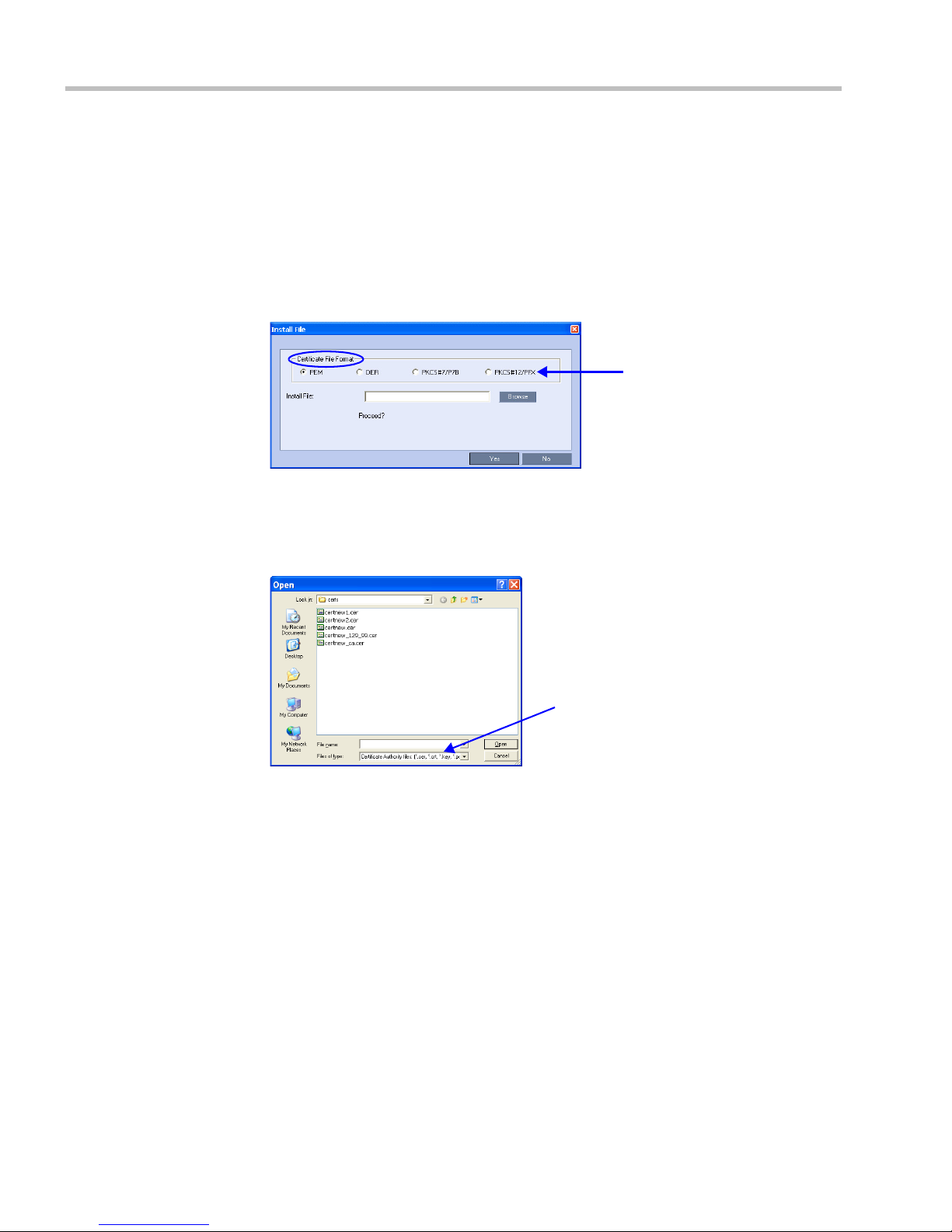
RealPresence Collaboration Server (RMX) 1500/2000/4000 Deployment Guide for Maximum Security Environments
File Types
File Types
a Copy (Ctrl + C) the certificate information from the Certificate Authority’s e-mail to
the clipboard.
b
Click
Paste Certificate
to paste the clipboard content into the
c Click the Send Certificate button to send the certificate to the RMX.
Option. Send Certificate File
After you have received the certificate file from the Certificate Authority:
a Click Send Certificate File.
The Install File dialog box is displayed.
b Select the Certificate File Format: PEM, DER, PKCS#7/P7B or PKCS#12PFX.
c Enter the certificate file name in the Install File field or click the Browse button.
The Open file dialog box is displayed. The files are filtered according to the file type
selected in Step b.
Send Certificate
dialog box.
d Enter the certificate file name in the File name field or click to select the certificate
file entry in the list.
e Click the Open button.
f In the Install File dialog box, click the Yes button to proceed.
The certificate is added to the Trusted Certificate List in the Certification Repository.
7 If there are additional Trusted Certificates to be added to the Certification Repository,
repeat steps 1 - 2, otherwise click the Update Repository button to complete Trusted
Certificate / CRL installation.
Before clicking the Update Repository button ensure that all CRLs have also been
added to the Certification Repository.
When the Update Repository button is clicked, all added Trusted Certificates and CRLs
are installed and the RMX displays an RMX Web Client/Manager connection termination
confirmation dialog box.
8 Click the OK button.
1-52 Polycom, Inc.
Page 59

Chapter 1-First Time Installation and Configuration
Additional configuration options for OCSP
Certificate Revocation
Certificate Revocation of IP Network and peer SIP TLS certificates for each defined IP Service
can be enabled, disabled and configured. OCSP and CRL are the two Certificate Revocation
methods available.
OSCP is the preferred method.
9 In the Revocation Method drop down menu select OCSP.
OSCP is the preferred method, and when selected, additional configuration options are
displayed.
10 In the Global Responder URL field, type the URL of the Global Responder to be used.
The format of the URL is validated and must be of the format:
http(s)://responder.example.com/ocsp. The URL can be either http or https.
If the Global Responder URL does not respond an Active Alarm is raised.
11 Clear the Use Responder Specified in Certificate check box.
Optional. If it is required that the Responder URL is taken from the Authority Information
Access (AIA) element of the Certificate, select the Use Responder Specified in Certificate
check box. If the certificate does not contain a Responder URL, the Global Responder URL
will be used.
12 Select the Allow Incomplete Revocation Checks check box.
If the check box is checked and the Global Responder or the Responder Specified in the
Certificate does not respond for any reason the certificate is not considered revoked.
If the Allow Incomplete Revocation Checks check box is and left unchecked and the Global
Responder or the Responder Specified in the Certificate do not respond correctly, the
certificate is considered revoked and system lock-out is possible.
It is therefore important that the user pings the Global Responder or the Responder
Specified in the Certificate to verify correct operation.
System Flag:
Should intermittent login problems occur when logging in to the RMX’s Management
Network, the OCSP_RESPONDER_TIMEOUT System Flag can be manually added to
system.cfg and its value set to the number of seconds the RMX is to wait for an OCSP
response from the OCSP Responder before failing the connection.
Default: 3 (seconds)
Range: 1-20 (seconds)
Polycom, Inc. 1-53
Page 60

RealPresence Collaboration Server (RMX) 1500/2000/4000 Deployment Guide for Maximum Security Environments
File Types
File Types
Installing the CRL
If CRL is the chosen method:
CRL - Requires at least one CRL file be installed, failing which an error message, At least one
CRL should be installed, is displayed.
This procedure is performed for each CRL that is to be added to the Certification Repository.
To add a CRL to the repository:
Repeat steps 1 - 7 for each CRL that is to be added to the Certification Repository.
1 In the CRL List tab, click the Add button.
2 The Install File dialog box is displayed.
3 Select the Certificate File Format: PEM or DER.
4 Enter the certificate file name in the Install File field or click the Browse button.
5 The Open file dialog box is displayed. The files are filtered according to the file type
selected in Step b.
6 Enter the Certificate file name in the File name field or click to select the certificate file
entry in the list.
7 Click the Open button.
The certificate is added to the CRL List in the Certification Repository.
8 If there are additional CRLs to be added to the Certification Repository, repeat steps 1 - 7,
otherwise click the Update Repository button to complete CRL / Trusted Certificate
installation.
Before clicking the Update Repository button ensure that all Trusted Certificates have
also been added to the Certification Repository.
When the Update Repository button is clicked, all added Trusted Certificates and CRLs
are installed and the RMX displays an RMX Web Client/Manager conne
ction termination
confirmation dialog box.
1-54 Polycom, Inc.
Page 61

9 Click the OK button.
10 Login to the RMX to proceed with further management tasks.
Switching to Secure Communication Mode
After the SSL/TLS certificate is installed, secure communications are enabled by modifying
the properties of the Management Network in the Management Network properties dialog box.
When Secure Communications Mode is enabled:
•Only https:// commands from the browser to the Control Unit IP Address of the
RMX are accepted.
•The RMX listens only on secured port 443.
• All connection attempts on port 80 are rejected.
• A secure communication indicator ( ) is displayed in the browser’s status bar.
To enable secure communications mode:
1 In the RMX Management pane, click IP Network Services.
2 In the IP Network Services list pane, double click the Management Network entry.
The Management Network Properties dialog box is displayed.
Chapter 1-First Time Installation and Configuration
3 Select the Secured RMX Communication check box.
4 Click OK.
5 In the Reset Confirmation dialog box, click Yes.
6 In the Please wait for system reset message box, click OK.
System restart may take up to five minutes.
Polycom, Inc. 1-55
Page 62

RealPresence Collaboration Server (RMX) 1500/2000/4000 Deployment Guide for Maximum Security Environments
Refresh the browser periodically until the RMX Web Client – Terms of Usage screen is
displayed
Procedure 6: Set System Configuration Flags
Maximum Security Environments have additional System Flags that control:
• Network Security
• User Management
• Strong Passwords
• Login and Session Management
• Cyclic File Systems
When the Maximum Security Environment is enabled by setting the
ULTRA_SECURE_MODE System Flag to YES, the enhanced security features are enforced.
Table 1-18 lists the default and recommended values of these flags in Ultra Secure Mode.
Table 1-18 System Flags and their default values
Flag Description
ALLOW_NONENCRYPT_PARTY_IN_ENC
RYPT_CONF
DISABLE_INACTIVE_USER Determines the number of consecutive days a user
ENABLE_CYCLIC_FILE_SY
STEM_ALARMS
FORCE_STRONG_PASSW
ORD_POLICY
HIDE_CONFERENCE_PAS
SWORD
LAST_LOGIN_ATTEMPTS When set to YES, the system displays a record of the
If YES, allows non-encrypted participants to connect
to encrypted conferences.
Default: No
can be inactive before being disabled.
Default: 30
Range: 1-90
When set to YES an Active Alarm is created when a
Cyclic File (Log, CDR, Audit) reaches a file retention
time or file storage capacity limit.
Default: YES
Enables or disables all password related flags. This
flag cannot be set to NO when the RMX is in Ultra
Secure Mode.
Default: YES
When set to YES, Conference and Chairman
passwords are replaced by asterisks in the RMX Web
Client, RMX Manager, Audit Event and Log files.
Default: YES
last Login of the user in the Main Screen of the RMX
Web Client or RMX Manager.
Default: YES
Recommended
Value
NO
30
YES
YES
YES
YES
1-56 Polycom, Inc.
Page 63

Table 1-18 System Flags and their default values
Chapter 1-First Time Installation and Configuration
Flag Description
MAX_KEEP_ALIVE_REQU
ESTS
The number of KeepAliveTimeout request intervals for
the Apache server.
In a Maximum Security Environment this value must
be set to a value of 1814400 to ensure that the RMX
Web Client / Manager will remain connected for
several hours, but not indefinitely. The exact time
period depends on the type of client that is connected
and the number of requests.
Default: 0 (This value should never be used as the
connection time is unlimited.)
(If the SESSION_TIMEOUT_IN_MINUTES System
Flag if configured, the RMX Web Client / Manager will
disconnect after the specified period if there is no
keyboard or mouse activity.)
MAX_NUMBER_OF_MANA
GEMENT_SESSIONS_PER
_SYSTEM
Determines the maximum number of management
sessions per system.
Default: 80
Range: 4-80
MAX_NUMBER_OF_MANA
GEMENT_SESSIONS_PER
_USER
Determines the maximum number of management
sessions per user.
Default: 20
Range: 4-80
Recommended
Value
1814400
80
10
MIN_PASSWORD_LENGTH Determines the minimum length of a user password.
Default: 15
Range: 15-20
MIN_PWD_CHANGE_FRE
QUENCY_IN_DAYS
Determines the minimum number of days that users
must retain passwords.
Default: 1
Range: 1-7
NUMERIC_CHAIR_PASS_
MIN_LEN
Determines the minimum length of a user chairperson
password.
Default: 9
Range: 9-16
NUMERIC_CONF_PASS_M
IN_LEN
Determines the minimum length of a conference
password.
Default: 9
Range: 9-16
OCSP_RESPONDER_TIME
OUT
The number of seconds the RMX is to wait for an
OCSP response from the OCSP Responder before
failing the connection.
Default: 3 (seconds)
Range: 1-20 (seconds)
15
1
9
9
Polycom, Inc. 1-57
Page 64

RealPresence Collaboration Server (RMX) 1500/2000/4000 Deployment Guide for Maximum Security Environments
Table 1-18 System Flags and their default values
Flag Description
PASSWORD_EXPIRATION
_DAYS
PASSWORD_EXPIRATION
_WARNING_DAYS
PASSWORD_HISTORY_SIZEDetermines how many previous passwords are
SESSION_TIMEOUT_IN_MI
NUTES
Determines the number of days that passwords
remain valid.
Default: 60
Range: 7-90
Determines how many days before password
expiration a warning of pending password expiration
will be displayed to the users.
Default: 7
Range: 7-14
recorded to prevent users from re-using previous
passwords. The list is cyclic, with the most recently
recorded password causing the deletion of the oldest
recorded password.
Default: 10
Range: 10-16
The number of minutes after which, if there is no input
from the user, the user’s connection to the RMX is
terminated.
Default: 10
Range: 1-999
Recommended
Value
60
7
10
10
USER_LOCKOUT When this flag is set to YES, a user is locked out of
USER_LOCKOUT_DURATI
ON_IN_MINUTES
USER_LOCKOUT_WINDO
W_IN_MINUTES
Modifying Flag Values
System security can be further strengthened by modifying the default flag values. These
modified values are applied to the system when the ULTRA_SECURE_MODE System Flag
is set to YES.
the system after three consecutive Login failures with
same User Name. The user is disabled and only the
administrator can enable the user within the system.
Default: YES
Determines the time period during which three
consecutive Login failures occur that will result in the
user being locked out.
Default: 0
Range: 0-480
Determines the time period for which the user is
locked out.
Default: 60
Range: 0-45000
YES
0
60
1-58 Polycom, Inc.
Page 65

Chapter 1-First Time Installation and Configuration
To modify the system configuration flags:
1 On the RMX menu, click Setup > System Configuration.
The System Flags dialog box is displayed.
2 Locate and double-click on the System Flag to be modified.
The Update Flag Name dialog box is displayed.
3 In the New Value field, enter the value required for the flag.
4 Click the OK button to close the Update Flag Name dialog box.
5 Repeat steps 2 to 4 for each flag value to be modified.
6 Click the OK button to close the System Flags dialog box.
7 In the Reset Confirmation dialog box, click Yes.
8 In the Please wait for system reset message box, click OK.
System restart may take up to five minutes.
9 Refresh the browser periodically until the RMX Web Client – Terms of Usage screen is
displayed.
10 Connect to the RMX. See "Connecting to the RMX” on page 1-46.
Procedure 7: Enable Network Separation (RMX 2000)
The RMX 2000, prior to the Network Separation procedure, hosts all signaling, management,
and media traffic via the LAN 2 port.
Network Separation is enabled/disabled according to the setting of the
SEPARATE_MANAGEMENT_NETWORK System Flag. When the System Flag is set to
YES, media and signaling traffic between IP endpoints and the RMX is hosted via the LAN
2 port, while RMX management sessions are hosted via the LAN 3 port.
— The RMX 1500 and RMX 4000 are designed with separate ports and networks for
signaling, management and media, therefore this flag setting is not relevant. For
more information see "Connecting Cables to the RMX 1500” on page 1-11 and
"Connecting Cables to the RMX 4000” on page 1-19.
Before plugging network cables in, ensure sure that the network infrastructure containing all the
devices (including the RMX) has two different networks: one for Management; the other for Signaling
& Media. Separation can be achieved either by two physical networks or by two virtual networks
(VLANs).
Polycom, Inc. 1-59
Page 66

RealPresence Collaboration Server (RMX) 1500/2000/4000 Deployment Guide for Maximum Security Environments
IP Endpoints
RMX Web Client / RMX Manager
Management Sessions
LAN 2 Port - Signaling
LAN 3 Port - Management
RMX
Enabling Network Separation
Figure 2 Signaling and Management Network Separation
To enable network separation:
1 On the RMX menu, click Setup > System Configuration.
The System Flags dialog box is displayed.
2 Locate and double-click on the SEPARATE_MANAGEMENT_NETWORK System
Flag entry.
The Update Flag Name dialog box is displayed.
3 In the New Value field, enter YES.
4 Click the OK button to close the Update Flag Name dialog box.
5 Click the OK button to close the System Flags dialog box.
6 In the Reset Confirmation dialog box, click No.
7 In the Collaboration Server Management pane, click the IP Network Services () button.
8 In the IP Network Services list pane, right-click the Management Network () entry
and select Properties.
9 Enter the Control Unit IP, Shelf Management IP and Subnet Mask addresses in their
respective field boxes.
10 Click the Routers tab.
11 Enter the Default Router IP Address.
12 Click the OK button.
A Reset Confirmation dialog box is displayed.
13 Connect a workstation that is connected to the Management LAN to the RMX’s LAN 3
port.
1-60 Polycom, Inc.
Page 67

Chapter 1-First Time Installation and Configuration
14 In the Reset Confirmation dialog box, click Yes.
System restart may take up to five minutes.
15 On the workstation that was connected to the RMX in Step 13, start the RMX Web Client
application:
a In the browser’s address line, enter the Control Unit IP Address in the format:
https://<Control Unit IP Address>.
b Press Enter.
16 Connect to the RMX. See "Connecting to the RMX” on page 1-46.
Procedure 8: Configure 802.1x Authentication
802.1x Authentication must be enabled for each Network Interface Controller (NIC).
To enable 802.1x Authentication:
1 In the RMX Menu, click Setup > Ethernet Settings
The Ethernet Settings dialog box is displayed.
2 For each NIC, modify the Ethernet Settings table fields as set out in Table 1-19.
Table 1-19 802.1x Authentication - Configuration
Field Description
802.1x Authentication For each NIC, click the arrow to open the drop-down menu and
Polycom, Inc. 1-61
select the 802.1x Authentication method:
• EAP-TLS
• PEAPv0
Note: EAP-MD5 and MSCHAPv2 are also available as options.
Selecting Off disables 802.1x Authentication.
Page 68

RealPresence Collaboration Server (RMX) 1500/2000/4000 Deployment Guide for Maximum Security Environments
Table 1-19 802.1x Authentication - Configuration
Field Description
User Enter the User name that the RMX will use to register with the
802.1x Authentication Server. This must be the RMX’s DNS name
and can be up to 256 characters.
If the Domain Name (DC) field was completed in the Certificate
Request, the User must be:
<Common Name (DNS)>@<Domain Name (DC)> as set out in
the Certificate Request.
Password
(EAP-MD5, PEAPv0
and MSCHAPv2 only)
Enter the Password, that the RMX will use to register with the
802.1x Authentication Server. Up to 256 Unicode characters can be
used. The Password is always displayed as four asterisks.
3 When 802.1x Authentication is configured for all NICs, click OK.
A warning message is displayed:
4 Click OK.
The RMX is disconnected from the network.
5 Disconnect the RMX’s LAN cables from the existing network and re-connect them to the
802.1x Authentication-enabled network.
6 Login to the RMX from the 802.1x Authentication-enabled network.
Procedure 9: Configure IVR Settings
Perform this procedure if a password is to be used to access the conference, otherwise skip.
1 In the RMX Management pane, click IVR Services.
The IVR Services list opens.
1-62 Polycom, Inc.
Page 69

Chapter 1-First Time Installation and Configuration
2 Right-click the Conference IVR Service and select Properties
3 Click the Conference Password tab.
The Conference IVR Service Properties - Conference Password dialog box is displayed.
4 Select the Enable Password messages.
5 Set Dial-in to Request Password
6 Set Dial-Out to Request Password
7 Click the Roll Call tab.
The Conference IVR Service Properties - Roll Call dialog box is displayed.
8 Select Enable Roll Call.
9 Click the OK button.
Polycom, Inc. 1-63
Page 70

RealPresence Collaboration Server (RMX) 1500/2000/4000 Deployment Guide for Maximum Security Environments
Terms of Usage
Banner
Accept
Button
Procedure 10: Optional. Modify Default Login and Main
Screen Banner Text
The Login and Main Screens of the RMX Web Client and the RMX Manager display warning
text banners cautioning users to the terms and conditions under which they may log into
and access the system.
The Login and Main Screen banners can be enabled when the RMX is not in Ultra Secure Mode
but cannot be disabled when the RMX is in Ultra Secure Mode.
The ULTRA_SECURE_MODE System Flag affects the display of the Login and Main Screen
banners as follows:
• When set to YES, the banners cannot be disabled.
• When set to NO, banner display is according to the check box selection in the Banners
Configuration dialog box.
Login Screen Banner
The Login screen banner displays the terms and conditions for system usage as follows:
1-64 Polycom, Inc.
Page 71

Chapter 1-First Time Installation and Configuration
Banner
The default text is:
You are accessing a U.S. Government (USG) Information System (IS) that is
provided for USG-authorized use only.
By using this IS (which includes any device attached to this IS), you
consent to the following conditions:
— The USG routinely intercepts and monitors communications on this IS
for purposes including, but not limited to, penetration testing,
COMSEC monitoring, network operations and defense, personnel
misconduct (PM), law enforcement (LE), and counterintelligence (CI)
investigations.
—
At any time, the USG may inspect and seize data stored on this IS.
— Communications using, or data stored on, this IS are not private,
are subject to routine monitoring, interception, and search, and may
be disclosed or used for any USG authorized purpose.
— This IS includes security measures (e.g., authentication and access
controls) to protect USG interests--not for your personal benefit or
privacy.
— Notwithstanding the above, using this IS does not constitute consent
to PM, LE or CI investigative searching or monitoring of the content
of privileged communications, or work product, related to personal
representation or services by attorneys, psychotherapists, or
clergy, and their assistants. Such communications and work product
are private and confidential. See User Agreement for details.
The user must click the Accept button before the Login screen is displayed.
Main Screen Banner
The Main Screen banner is displayed at the bottom of the screen. It is intially blank and can
be customized
Polycom, Inc. 1-65
Page 72

RealPresence Collaboration Server (RMX) 1500/2000/4000 Deployment Guide for Maximum Security Environments
Customizing Login and Main Screen Banners
The Login and Main Screen banners can be customized when the RMX is in either Ultra
Secure Mode or non-Ultra Secure Mode.
To customize the banners:
1 In the RMX menu, click Setup > Customize Display Settings > Banners
Configuration.
The Banners Configuration dialog box opens.
2 Customize the banners by modifying the following fields:
Table 1-20 Banner Configuration
Description
Field
Check Box Text Field
Login Page
Banner
Main Page
Banner
Select or clear the
check box to enable
or disable the
display of the
banner.
Banner display
cannot be disabled
in Ultra Secure
Mode.
Edit the text in this field to
meet local requirements:
• Banner content is
multilingual and uses
Unicode, UTF-8
encoding. All text and
special characters can
be used.
• Maximum banner size
is 100KB.
• The banner may not be
left blank in Ultra
Secure Mode.
3 Click the OK button.
Restore Default
Button
Click the button to
restore the default
text to the banner.
1-66 Polycom, Inc.
Page 73

Chapter 1-First Time Installation and Configuration
Procedure 11: Rename the Default POLYCOM User
To rename the default POLYCOM user:
1 In the RMX Management pane, click the Users ( ) button.
2 The Users pane is displayed.
3 Select the POLYCOM user.
4 Select Rename User in the menu.
The Rename User dialog box is displayed.
5 Enter a new User Name in the New User Name field and click OK.
The user is renamed and is forced to change his/her password.
Procedure 12: Disable Inline AutoComplete Option in Web
Browser
To protect both User Names and Passwords it is recommended to disable the Inline
AutoComplete option in the web browser on the workstation.
To disable the Inline AutoComplete option in Internet Explorer®:
1 In the web browser menu, select Tools > Internet Options.
2 Select the Advanced tab.
3 Clear the Use inline AutoComplete check box.
Polycom, Inc. 1-67
Page 74

RealPresence Collaboration Server (RMX) 1500/2000/4000 Deployment Guide for Maximum Security Environments
4 Click the OK button.
Procedure 13: Configure White List Access
For security reasons it is important that a list of devices permitted to connect to the RMX is
configured. The White List contains the addresses of all IP devices permitted to connect to
the RMX.
To view or modify the White List:
1 In the RMX Management pane, click the IP Network Services.
2 In the IP Network Services list pane, double-click the Management Network entry.
3 In the Management Network Properties dialog box click the WhiteList tab.
The WhiteList dialog box is displayed.
— If there are no entries in the White List, it is disabled to prevent lock out.
— If the White List is disabled non of the IP addresses in the list are displayed.
— The Add and Remove buttons are only active if the Enable Whitelist check box is
selected.
1-68 Polycom, Inc.
Page 75

4 Select the Enable Whitelist check box.
Chapter 1-First Time Installation and Configuration
All IP addresses in the list are displayed and the Add and Remove buttons become
active.
5 Modify the White List.
Both IPv4 and IPv6 addresses are supported and the system will only allow entry of the
type of IP addresses for which it is configured according to Table 1-21.
Table 1-21 IP Address Modes
IP Address Modes
RMX Workstation / Device
IPv4
IPv6
IPv4 & IPv6
IPv4
IPv4 & IPv6
IPv6
IPv4 & IPv6
IPv4
IPv6
IPv4 & IPv6
— If the system changes its IP addressing mode (e.g. from IPv4 only to both IPv4 &6)
while the White List is enabled, the White List is disabled and a message, White list
has been disabled please reconfigure, is displayed.
— IPv4 addresses can be added as a range by substituting the 3rd and 4th dotted
decimal numbers of the IP address with * characters, e.g. 11.10.*.*
6 Add IP addresses to the White List:
Polycom, Inc. 1-69
Page 76

RealPresence Collaboration Server (RMX) 1500/2000/4000 Deployment Guide for Maximum Security Environments
For each IP address to be added to the White List:
a In the Add IP Address field enter an IP address to be added to the White List and
click the Add button to add the IP address to the White List.
If an invalid IP address is entered, an error message is displayed and the
administrator is prompted to enter a correct IP address.
b When all the IP addresses have been added, click OK.
A message is displayed: Applying white list will limit RMX web access to the configured
IP list, are you sure you want to continue?
c Click Yes to apply the modified White List.
1-70 Polycom, Inc.
Page 77
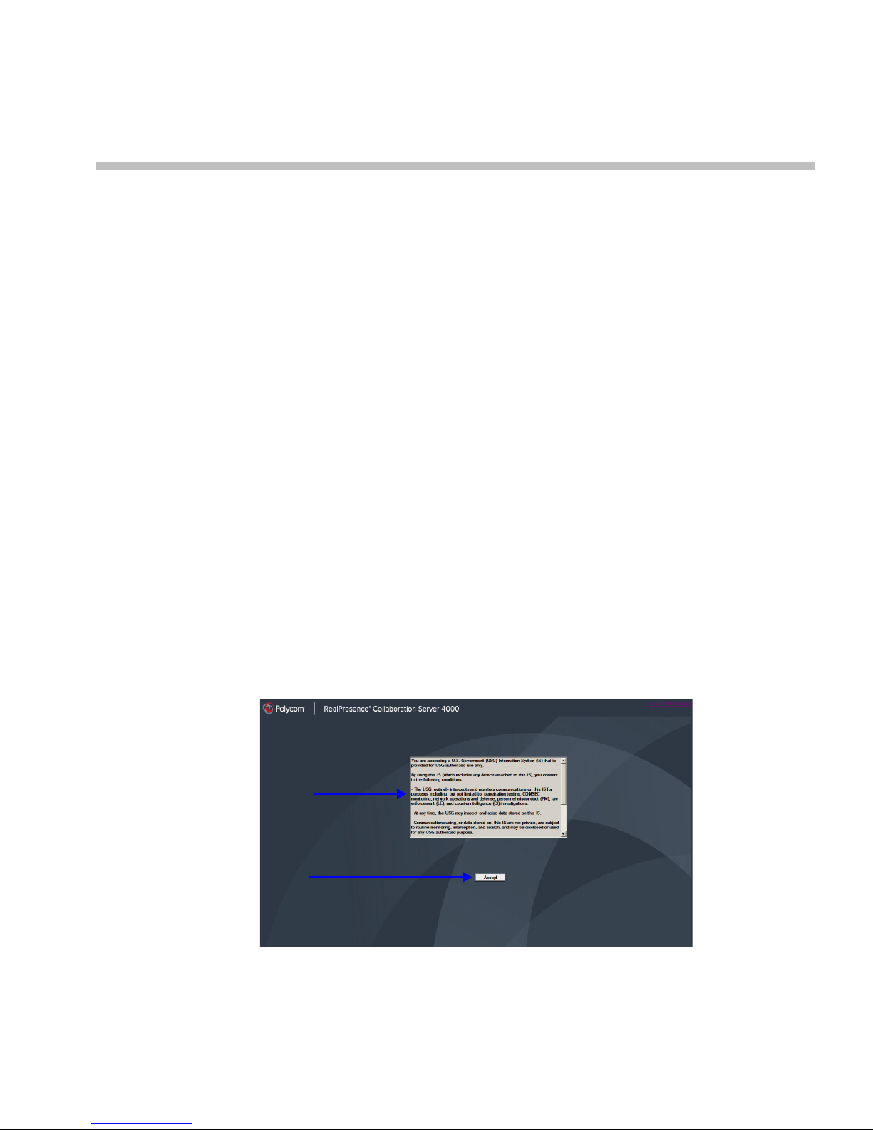
Basic Operation
Terms of Usage
Banner
Accept
Button
The most common operations performed via the RMX Web Client are:
• Starting, monitoring and managing conferences
• Monitoring and managing participants and endpoints as individuals or groups.
— Participant – A person using an endpoint to connect to a conference. When using a
Room System, several participants use a single endpoint.
— Endpoint – A hardware device, or set of devices, that can call, and be called by an
MCU or another endpoint. For example, an endpoint can be a phone, a camera and
microphone connected to a PC or an integrated Room System (conferencing system).
— Group – A group of participants or endpoints with a common name.
Starting the RMX Web Client
Before you begin, get the following information from your system administrator:
• Username
• Password
• MCU Control Unit IP Address
To start the RMX Web Client:
1 In the browser address line, enter
https://<Control Unit IP Address> and press the Enter key.
The RMX Web Client – Terms of Usage screen is displayed.
2
Polycom, Inc. 2-1
2 Click the Accept button to agree to the terms and conditions displayed in the banner.
Page 78

RealPresence Collaboration Server (RMX) 1500/2000/4000 Deployment Guide for Maximum Security Environments
Last Successful Login
Unsuccessful Logins
The Login - Welcome screen is displayed:
3 Enter your User Name.
4 Enter your Password.
5 Click Login.
The RMX Web Client - Main Screen is displayed.
The system can display a record of the last Login of the user. It is displayed in the Main
Screen of the RMX Web Client or RMX Manager. The user Login Record display is enabled
when the LAST_LOGIN _ATTEMPTS System Flag is set to YES, which is the default
when the ULTRA_SECURE_MODE System Flag is set to YES.
Both lists display the:
— Date and Time of the Login attempt.
— IP Address of the workstation initiating the Login attempt.
The list of unsuccessful Logins can contain up to ten records.
Failed Login attempts are written to the system Log Files and are recorded as Audit
Events. The Audit files can be retrieved by the Administrator User.
2-2 Polycom, Inc.
Page 79

RMX Web Client Screen Components
Conferences
List
List
Status Bar
RMX
Management
Address
Book
Conference
Temp la te s
Tab
Banner
The RMX 2000 Web Client’s main screen consists of five panes:
• Conference List
• List Pane
• RMX Management
• Status Bar
• Address Book
• Conference Templates
For more information, see the RMX 2000 Administrator’s Guide, "Users, Connections and
Notes” on page 10-1.
Chapter 2-Basic Operation
The main screen can be customized. For more information, see "Customizing the Main
Screen” on page 2-10.
Polycom, Inc. 2-3
Page 80
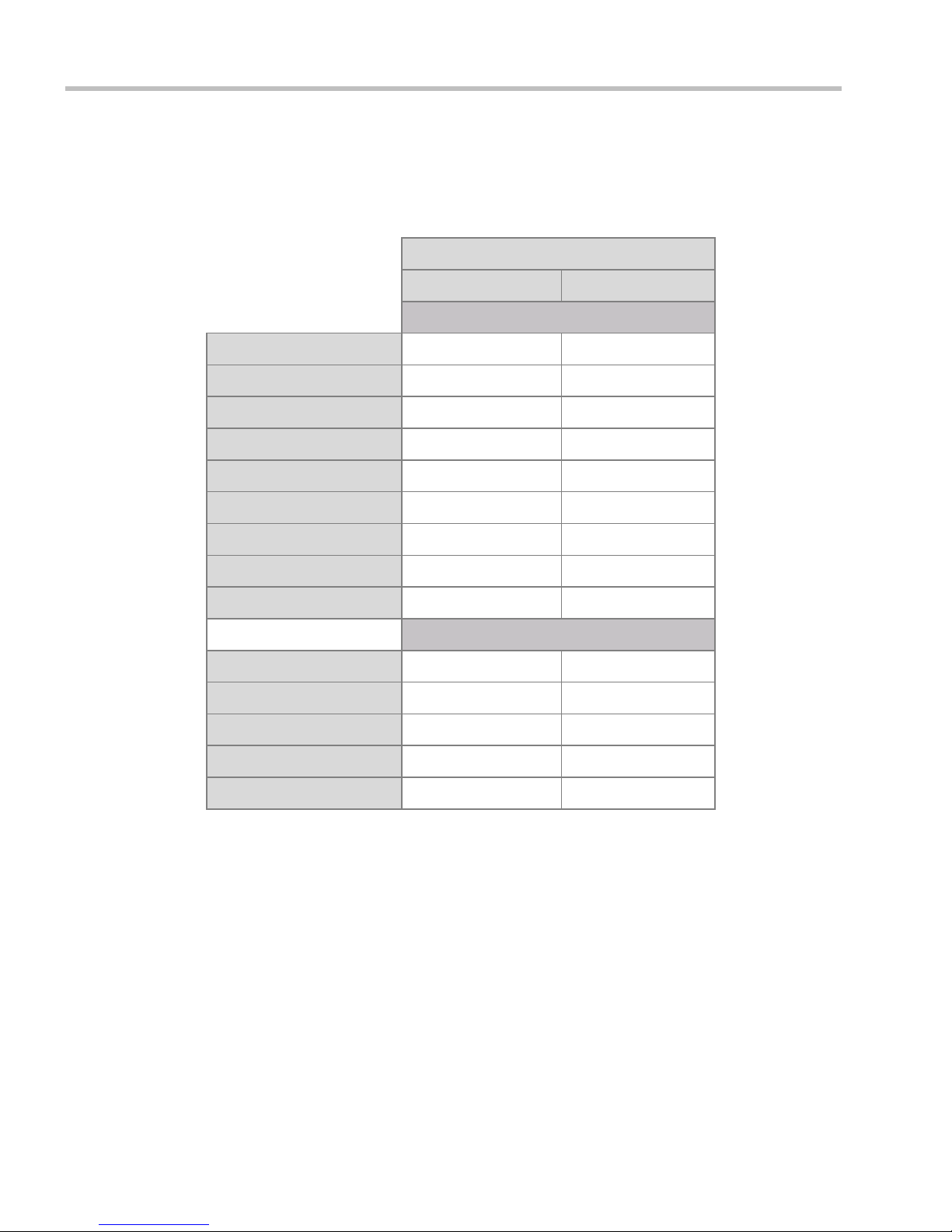
RealPresence Collaboration Server (RMX) 1500/2000/4000 Deployment Guide for Maximum Security Environments
Viewing and System Functionality Permissions
Viewing
and
System Functionality
permissions for Administrators and Operators are
summarized in Table 2-1:
Table 2-1 Viewing and System Permissions
Authorization Level
Operator Administrator
Viewing Permissions
Conference List
List Pane
Address Book
Conference Templates
Status Bar
RMX Management
Conference Alarms
Conference Status
Configurations
Start Conferences
Monitor Conferences
Monitor Participants
Solve Basic Problems
Modify MCU Configuration
Conferences List
If you are logged in as a user with Operator or Administrator permissions:
The Conferences pane lists all the conferences currently running on the MCU along with their
Status, Conference ID, Start Time and End Time data. The number of ongoing conferences is
displayed in the pane’s title.
System Functionality
2-4 Polycom, Inc.
Page 81

List Pane
Toolbar
List Headers
Conference Data
New Conference
Delete Conference
Stop Recording
Start/Resume/Pause Recording
Save Conference
to Template
Total number of participants
Chapter 2-Basic Operation
The Conferences list toolbar contains the following buttons:
• New Conference – to start a new ongoing conference.
• Delete Conference – delete the selected conference(s).
If Conference Recording is enabled the following are displayed in color:
— Start/Resume Recording – start/resume recording.
— Stop Recording – stop recording.
— Pause – toggles with the Start/Resume button.
The List pane displays details of the item selected in the Conferences pane or RMX
Management pane. The title of the pane changes according to the selected item.
RMX Management
The RMX Management pane lists the entities that need to be configured to enable the RMX to
run conferences. Only users with Administrators permission can modify these parameters.
The RMX Management pane is divided into two sections:
• Frequently Used – parameters often configured monitored or modified.
• Rarely Used – parameters configured during initial system set-up and rarely modified
afterward.
Status Bar
The Status Bar at the bottom of the RMX Web Client contains System and Participant Alerts
tabs as well as Port Usage Gauges and an MCU State indicator.
Polycom, Inc. 2-5
Page 82

RealPresence Collaboration Server (RMX) 1500/2000/4000 Deployment Guide for Maximum Security Environments
Active
Alarms
Faults
List
Audio Ports In Use
Total Allocated Audio Ports In System
Video Port Usage Indicator
Total Allocated Video Ports (HD resolution) In System
Video Ports In Use
Audio Port Usage Indicator
Audio and Video High Port Usage Threshold
System Alerts
This is a list of system problems. The alert indicator flashes red when at least one system
alert is active. The flashing continues until a user with Operator or Administrator
permission reviews the list.
The System Alerts pane is opened and closed by clicking the System Alerts button in the left
corner of the Status Bar.
For more information about Active Alarms and Faults List, see the
RealPresence Collaboration Server (RMX) 1500/2000/4000 Administrator’s Guide, "System and
Participant Alerts” on page 14-18.
Participant Alerts
This is a list of participants that are experiencing connection problems. It is sorted by
conference.
The Participant Alerts pane is opened and closed by clicking the Participant Alerts button in
the left corner of the Status Bar.
Port Usage Gauges
The Port Usage gauges indicates:
• The total number of Video or Voice ports in the system according to the Video/Voice Port
Configuration.
• The number of Video and Voice ports in use.
•The High Port Usage threshold.
2-6 Polycom, Inc.
Page 83

Chapter 2-Basic Operation
Video Port Usage Indicator
Total Allocated Video Ports (HD resolution) In System
Video Ports In Use
Video High Port Usage Threshold
Progress Indicator Bar Time Remaining
The High Port Usage threshold represents a percentage of the total number of video or voice
ports available. It is set to indicate when resource usage is approaching its maximum,
resulting in no free resources to run additional conferences. When port usage reaches or
exceeds the threshold, the red area of the gauge flashes and a System Alert is generated. The
default port usage threshold is 80% and it can be modified by the system administrator. For
more information, see the
RealPresence Collaboration Server (RMX) 1500/2000/4000 Administrator’s Guide for Maximum
Security Environments, "Setting the Port Usage Threshold” on page 14-60.
Address Book
MCU State
The MCU State indicator displays one of the following:
• – The MCU is starting up. The time remaining until the system startup is complete is displayed between brackets while a green progress indicator bar
indicates the start-up progress.
• – The MCU is functioning normally.
• – The MCU has a major problem. MCU behavior could be affected
and attention is required.
The Address Book is a list of Participants and Groups that have been defined on the RMX. The
information in the Address Book can be modified only by an administrator. All RMX users
can, however, view and use the Address Book to assign participants to conferences.
The Address Book toolbar contains a Quick Search field and the following six buttons:
• New Participant • New Group
Polycom, Inc. 2-7
• Delete Participant • Delete Group
• Import Address Book • Export Address Book
Page 84

RealPresence Collaboration Server (RMX) 1500/2000/4000 Deployment Guide for Maximum Security Environments
Audio Participant
Video Participant
Group
Delete Group
New Participant
Import Address Book
New Group
Export Address Book
Delete Participant
Click
to hide
Address
Book
Quick
Search
Click tab to open Address Book
Address Book entries are listed according to:
• Type – whether an individual Participant or a Group of participants
• Name – of the participant or group
• Dialing Direction – Dial-in or Dial-out
• IP Address/Phone – of the participant
Conference Templates
2-8 Polycom, Inc.
Displaying and Hiding the Address Book
The first time you access the Collaboration Server Web Client, the Address Book pane is
displayed. You can hide it by clicking the anchor pin ( ) button.
The Address Book pane closes and a tab appears at the right edge of the screen.
Click the tab to re-open the Address Book.
Conference Templates enable administrators and operators to create, save, schedule and
activate identical conferences.
A Conference Template:
• Saves conference and Operator conference Profiles.
• Saves all participant parameters including their Personal Layout and Video Forcing
settings.
• Simplifies the setting up Telepresence conferences where precise participant layout and
video forcing settings are crucial.
Page 85

Chapter 2-Basic Operation
Conference Templates Tab
Number of Saved Conference Templates
New Template
Delete Template
Start Template
Schedule Template
Number of Saved Conference Templates
List of
Saved
Temp la te s
Click to hide the
Conference Templates List
Displaying and Hiding Conference Templates
The Conference Templates list pane is initially displayed as a closed tab in the RMX Web Client
main window. The number of saved Conference Templates is indicated on the tab.
Clicking the tab opens the Conference Templates list pane.
Hide the Conference Templates list pane by clicking the anchor pin ( ) button in the top right
corner of the pane.
The Conference Templates list pane closes and a tab appears in the top right corner of the
screen.
Polycom, Inc. 2-9
Page 86

RealPresence Collaboration Server (RMX) 1500/2000/4000 Deployment Guide for Maximum Security Environments
Customizing the Main Screen
You can customize the main screen according to your preferences. Pane sizes can be
changed, column widths can be adjusted and data lists can be sorted.
Customization settings are automatically saved for each logged-in user.
The next time the RMX Web Client is opened, the main screen settings appear as they were when
the user exited the application.
To re-size a pane:
>> Move the pointer over the pane border and when the pointer becomes a click and
drag the pane border to the required size and release the mouse button.
To adjust column width:
1 In the column header row, place the pointer on the vertical field- separator bar of the
column.
2 When the pointer becomes a , click and drag the field separator bar to the required
column size and release the mouse button.
To sort the data by any field (column heading):
1 In the Conference list or List view pane, click on the column heading of the field to be
used for sorting.
A or symbol appears in the column heading indicating that the list is sorted by
this field, as well as the sort order.
2 Click on the column heading to toggle the column’s sort order.
To change the order of columns in a pane:
>> Click the column heading to be moved and drag it to its new position. When a set of red
arrows appears indicating the column’s new position, release the mouse button.
To restore the RMX 2000 display window to its default configuration:
>> On the RMX 2000 menu, click View > Restore RMX Display Defaults.
2-10 Polycom, Inc.
Page 87

Chapter 2-Basic Operation
Toolbar View
List View
Toolbar View Button
List View Button
The new position of the
Networks icon
List
View
Customizing the RMX Management Pane
The RMX Management pane can be viewed either as a list or as a toolbar.
To switch between Toolbar and List Views:
>> In the RMX Management pane, click the Toolbar View button to switch to Toolbar view.
>> In Toolbar view, click the List View button to switch back to List view.
You can move items between the Frequently Used and Rarely Used sections depending on the
operations you most commonly perform and the way you prefer to work with the RXM Web
Client.
This only works in List view because in Toolbar view, all items are represented by icons.
To expand or Collapse the Frequently Used and Rarely Used sections:
The Frequently Used and Rarely Used sections can be expanded or collapsed by clicking the
and buttons.
To move items within and between the Frequently Used and Rarely Used sections:
1 In the RMX Management pane click and drag the icon of the item that you wish to move.
An indicator line ( ) appears indicating the new position of the icon.
2 Release the mouse button when the icon is in the desired position.
Polycom, Inc. 2-11
Page 88

RealPresence Collaboration Server (RMX) 1500/2000/4000 Deployment Guide for Maximum Security Environments
Starting a Conference
There are several ways to start a conference:
• Clicking the New Conference button in the Conferences pane. For more information, see
"Starting a Conference from the Conferences Pane” on page 2-12.
• Dialing in to a Meeting Room.
— A Meeting Room is a conference that is saved on the MCU. It remains in passive
mode until it is activated by the first participant, or the meeting organizer, dialing
in.
For more information about Meeting Rooms, see the RealPresence Collaboration Server
(RMX) 1500/2000/4000 Administrator’s Guide for Maximum Security Environments,
"Meeting Rooms” on page 3-1.
• Dialing in to an Ad Hoc Entry Queue which is used as the access point to the MCU.
For a detailed description of Ad Hoc Entry Queues, see the Collaboration Server 1500/2000/
4000 Administrator’s Guide for Maximum Security Environments, "Entry Queues, Ad Hoc
Conferences and SIP Factories” on page 4-1.
•Start a Reservation:
— If the Start Time of the Reservation is past due the conference becomes ongoing
immediately.
— If the Start Time of the Reservation is in the future the conference becomes ongoing,
at the specified time on the specified date.
For more information, see "Starting a Reservation” on page 2-20.
• Start from any Conference Template saved in the Conference Templates list.
Although SVC Conferencing Mode options are available in Conference Profiles, it is advised that
they not be used with Version 8.1.4.J.
Starting a Conference from the Conferences Pane
To start a conference from the Conference pane:
1 In the Conferences pane, click the New Conference ( ) button.
2-12 Polycom, Inc.
Page 89

Chapter 2-Basic Operation
The New Conference – General dialog box opens.
The system displays the conference’s default Name, Duration and the default Profile,
which contains the conference parameters and media settings.
The RMX automatically allocates the conference ID, when the conference starts.
In most cases, the default conference ID can be used and you can just click OK to launch
the conference. If required, you can enter a conference ID before clicking OK to launch
the conference.
You can use the New Conference - General dialog box to modify the conference
parameters. If no defined participants are to be added to the conference, or you do not
want to add additional information, click OK.
Polycom, Inc. 2-13
Page 90

RealPresence Collaboration Server (RMX) 1500/2000/4000 Deployment Guide for Maximum Security Environments
General Tab
2 Define the following parameters:
Table 2-2 New Conference – General Options
Field Description
Display Name The Display Name is the conferencing entity name in native
language character sets to be displayed in the RMX Web Client.
In conferences, Meeting Rooms and Entry Queues the system
automatically generates an ASCII name for the Display Name field
that can be modified using Unicode encoding.
•
English text uses ASCII encoding and can contain the most
characters (length varies according to the field).
• European and Latin text length is approximately half the length
of the maximum.
• Asian text length is approximately one third of the length of the
maximum.
The maximum length of text fields also varies according to the
mixture of character sets (Unicode and ASCII).
Maximum field length in ASCII is 80 characters.
If the same name is already used by another conference, Meeting
Room or Entry Queue, the Collaboration Server displays an error
message requesting you to enter a different name.
Note: This field is displayed in all tabs.
Duration Define the duration of the conference in hours using the format
HH:MM (default 01:00).
Note: This field is displayed in all tabs.
Routing Name Routing Name is the name with which ongoing conferences,
Meeting Rooms and Entry Queues register with various devices on
the network such as gatekeepers. This name must defined using
ASCII characters.
Comma, colon and semicolon characters cannot be used in
the Routing Name.
The Routing Name can be defined by the user or automatically
generated by the system if no Routing Name is entered as follows:
• If ASCII characters are entered as the Display Name, it is used
also as the Routing Name
• If a combination of Unicode and ASCII characters (or full
Unicode text) is entered as the Display Name, the ID (such as
Conference ID) is used as the Routing Name.
If the same name is already used by another conference, Meeting
Room or Entry Queue, the RMX displays an error message and
requests that you to enter a different name.
2-14 Polycom, Inc.
Page 91

Chapter 2-Basic Operation
Table 2-2 New Conference – General Options (Continued)
Field Description
Profile The system displays the name of the default Conference Profile.
Select the required Profile from the list.
The Conference Profile includes the Conference line rate, media
settings and general settings.
For a detailed description of Conference Profiles, see the
RealPresence Collaboration Server (RMX) 1500/2000/4000
Administrator’s Guide for Maximum Security Environments,
"Conference Profiles” on page 1-1.
ID Enter the unique-per-MCU conference ID. If left blank, the MCU
automatically assigns a number once the conference is launched.
This ID must be communicated to conference participants to
enable them to dial in to the conference.
Conference Password Enter a password to be used by
participants to access the conference.
If left blank, no password is assigned to
the conference.
This password is valid only in
conferences that are configured to
prompt for a conference password.
Chairperson Password Enter a password to be used by the
RMX to identify the Chairperson and
grant him/her additional privileges. If
left blank, no chairperson password is
assigned to the conference.
This password is valid only in conferences that are configured to prompt for
a chairperson password.
Reserve Resources for
Video Participants
Enter the number of video participants for which the system must
reserve resources.
Default: 0 participants.
Maximum: 80 participants.
Reserve Resources for
Audio Participants
Enter the number of audio participants for which the system must
reserve resources.
Default: 0 participants.
Maximum: 120 participants.
These fields are
numeric and have a
default length of 4
characters. The
administrator can
modify them in the
Setup - System
Configuration settings.
For more information,
see the RealPresence
Collaboration Server
(RMX) 1500/2000/4000
Administrator’s Guide
for Maximum Security
Environments, "System
Configuration” on
page 14-22.
3 If all participants are undefined, dial-in and no additional information is required for
the new conference, click OK.
4 To add participants from the Participants Address Book or to define participants (mainly
dial-out participants) click the Participants tab.
Polycom, Inc. 2-15
Page 92

RealPresence Collaboration Server (RMX) 1500/2000/4000 Deployment Guide for Maximum Security Environments
Participants
List
Participants Tab
This procedure is optional.
The Participants tab is used to add participants to the conference from the Address Book.
It is also used to add defined dial-out participants to the conference. Defined dial-out participants are
connected to the conference automatically when the conference is launched
5 Click the Participants tab.
The Participants tab opens.
When defining a new conference, the Participants List is empty.
2-16 Polycom, Inc.
Page 93

Chapter 2-Basic Operation
The following table describes the information displayed in the Participants List and the
operations that can be performed.
Table 2-3 New Conference – Participants Tab
Column / Button Description
Participants List
Name A Unicode field that displays the participant’s name and an icon
representing the endpoint type: Audio Only or Video.
IP Address/Phone Indicates the IP address or phone number of the participant’s
endpoint.
• For dial-out connection, displays the IP address or phone
number of the endpoint called by the Polycom® RMX™ 1800.
• For dial-in connection, displays the participant’s IP address or
phone number used to identify and route the participant to the
appropriate conference.
Alias Name
(IP Only)
Network The network communication protocol used by the endpoint to
Dialing Direction Dial-in – The participant dials in to the
Encryption Displays whether the endpoint uses encryption for its media.
Buttons
New Click to define a new participant.
Remove Click to remove the selected participant from the conference.
Add from Address Book Click to add a participant from the Address Book to the
Displays the alias name of an H.323 endpoint.
connect to the conference: H.323 or ISDN/PSTN.
conference
Dial-out – The Collaboration Server dials out to the
participant
The default setting is Auto, indicating that the endpoint must
connect according to the conference’s encryption setting.
Note: The H.320 protocol (ISDN/PSTN) does not support
encryption.
For more information, see the RealPresence Collaboration Server
(RMX) 2000/4000 Administrator’s Guide for Maximum Security
Environments, "Adding a new participant to the Address Book
Directly” on page 5-4.
conference.
Lecturer This option is used to activate the Lecture Mode. Select the
Participants can be added to the conference in the following methods:
— Defining a new participant during the definition of the conference (clicking the
New button).
Polycom, Inc. 2-17
participant you want to designate as Lecturer from the drop-down
menu list of conference participants.
Page 94

RealPresence Collaboration Server (RMX) 1500/2000/4000 Deployment Guide for Maximum Security Environments
— Adding pre-defined participants from the Address Book by either selecting the
participants from the list or dragging and dropping the participants from the
Address Book to the Participants list.
— Dial-in participants can connect to the conference after it was started (without
using the New Conference - Participants dialog box).
— Once the conference has started, participants can be added to a conference directly
from the Participants Address Book without having to use the New Conference –
Participants tab. For more details, see "Adding Participants from the Address Book” on
page 2-35.
To add participants from the Address Book:
6 In the Participants List, click the Add from Address Book button to open the Participants
Address Book.
7 In the Participants Address Book, select the participants that you want to add to the
conference and click the Add button.
Standard Windows multiple selection techniques can be used in this procedure.
8 The selected participants are assigned to the conference and appear in the Participant
List.
9 Select additional Participants or click the Close button to return to the Participants tab.
2-18 Polycom, Inc.
Page 95

Chapter 2-Basic Operation
Information Tab
In the Info fields, you can add general information about the conference, such as contact
person name, company name, billing code, etc.
This information is written to the Call Detail Record (CDR) when the conference is launched.
Changes made to this information once the conference is running are not saved to the CDR.
This procedure is optional.
The information entered into these fields does not affect the conference.
To add information to the conference:
10 Click the Information tab.
The Information tab opens.
11 Enter the following information:
Table 2-4 New Conference – Info Options
Field Description
Info1, 2, 3 There are three information fields that allow you to enter general
information for the conference such as company name, contact person
etc.
Unicode can be used in these fields.
The maximum length of each field is 80 characters.
Billing Enter the conference billing code if applicable.
12 Click OK.
An entry for the new conference appears in the Conferences pane.
If an ISDN/PSTN dial-in number was assigned to the conference either automatically
or manually, this number can be viewed in the Conferences pane.
If no participants were defined for the conference or as long as no participants are
connected, the indication Empty and a warning icon ( ) appear in the Status column in
the Conferences pane.
The status changes when participants connect to the conference.
Polycom, Inc. 2-19
Page 96

RealPresence Collaboration Server (RMX) 1500/2000/4000 Deployment Guide for Maximum Security Environments
If no participant connects within the time specified in the Conference Profiles > Auto
Terminate > Before First Joins field, the conference is automatically terminated by the
system.
Starting a Reservation
To start a conference from the Reservation Calendar:
1 In the RMX Management pane, click the Reservation Calendar
button ( ).
The Reservation Calendar is displayed.
2 Click the New Reservation ( ) button.
The New Reservation – General tab dialog box opens.
2-20 Polycom, Inc.
Page 97

Chapter 2-Basic Operation
3 Optional. Select the Enable ISDN/PSTN Dial-in check box if you want ISDN and
PSTN participants to be able to connect directly to the conference.
4 If Enable ISDN/PSTN Dial-in option is selected, either enter a dial-in number, or leave
the Dial-in Number field blank to let the system automatically assign a number from the
dial-in range defined for the selected ISDN/PSTN Network Service.
5 Click the OK button.
A confirmation box is displayed stating that the Reservation time is past due and that the
conference will become ongoing.
6 Click the OK button.
The conference is started. If an ISDN/PSTN dial-in number was assigned to the
conference either automatically or manually, this number can be viewed in the
Conferences pane.
For more information about Reservations, see the RealPresence Collaboration Server (RMX)
1500/2000/4000 Administrator’s Guide for Maximum Security Environments, "Reservations” on
page 6-1.
Starting an Ongoing Conference From a Template
An ongoing conference can be started from any Conference Template saved in the
Conference Templates list.
To start an ongoing conference from a Template:
1 In the Conference Templates list, select the Template you want to start as an ongoing
conference.
2 Click the Start Conference from Template
or
Right-click and select Start Conference from Template.
() button.
Polycom, Inc. 2-21
Page 98

RealPresence Collaboration Server (RMX) 1500/2000/4000 Deployment Guide for Maximum Security Environments
ISDN/PSTN
Endpoint
IP Endpoint
MCU
IP Endpoint
Network
“Conference
Password?”
Conference
IVR Service
Maple Room
Conference ID: 1001
Password 34567
Oak Room
Conference ID: 1002
Password 71356
The conference is started.
If a Conference Template is assigned a dial-in number that is already assigned to an ongoing
conference, Meeting Room, Entry Queue or Gateway Profile, when the template is used to start an
ongoing conference or schedule a reservation it will not start. However, the same number can be
assigned to several conference templates provided they are not used to start an ongoing conference
at the same time. If a dial in number conflict occurs prior to the conference’s start time, an alert
appears: “ISDN dial-in number is already assigned to another conferencing entity” and the
conference cannot start.
The name of the ongoing conference in the Conferences list is taken from the Conference
Template Display Name.
Participants that are connected to other ongoing conferences when the template
becomes an ongoing conference are not connected.
If an ongoing conference, Meeting Room or Entry Queue with the same Display Name, Routing
Name or ID already exist in the system, the conference will not be started.
For detailed description of Conference Templates, see RealPresence Collaboration Server 800s
Administrator’s Guide for Maximum Security Environments, "Conference Templates” on page 7-1.
Connecting to a Conference
Direct Dial-in
Participants must be provided with a dialing string which can vary according to the
network type, conference password and chairperson password.
Participants dial the conference dial-in string and are connected to the conference IVR
Service. Once the correct information, such as the conference password and chairperson
password are entered, the participants are connected to the conference.
Dial-in Connection via IVR System
2-22 Polycom, Inc.
Page 99

Chapter 2-Basic Operation
The chairperson can use the chairperson password as the conference password and does not
need to enter the conference password.
Participants connecting to HD Video Switching conferences must have HD capable endpoints and
must connect using the same line rate as defined for the conference. If not, they are connected as
Secondary (audio only participants).
H.323 Participants
For H.323 participants, the dialing string is composed of the MCU prefix in the Gatekeeper
and the Conference ID.
Example:
Prefix in gatekeeper 925
Conference ID 1001
Conference Name Maple_Room
>> The participant dials
If there is no gatekeeper defined for the network, H.323 participants dial
signaling host IP address and the conference ID, separated by
Example:
MCU (Signaling Host) IP address
Conference ID 1001
>> The participant dials 172.22.30.40##1001
9251001 or 925Maple_room
172.22.30.40
##.
the MCU’s
Polycom, Inc. 2-23
Page 100

RealPresence Collaboration Server (RMX) 1500/2000/4000 Deployment Guide for Maximum Security Environments
ISDN/ PSTN
Endpoint
IP Endpoint
IP Endpoint
Network
MCU
“Conference
ID?”
“Conference
Password?”
Entry Queue
Name: DefaultEQ
Numeric ID: 1000
Dial-in Number: 9251000
Oak Room
Conference ID: 1002
Password 71356
Maple Room
Conference ID: 1001
Password 34567
Conference
IVR Service
MCU Prefix in
Gatekeeper - 925
Entry Queue Access
Access via an Entry Queue allows all participants to dial the same entry point that acts as a
routing lobby. Once in the Entry Queue, participants are guided to the conference according
to the conference ID they enter.
Figure 2-1: Dial-in Connection via Entry Queue
Dialing is executed in the same way as for conferences, where the Entry Queue ID/Name
replaces the Conference ID/Name.
H.323 Participants
H.323 participants dial [Gatekeeper Prefix][Entry Queue ID/Name].
Example:
Prefix in gatekeeper 925
Entry Queue ID 1000
>> The participant dials
H.323 participants can bypass the Entry Queue IVR voice messages by adding the correct
Conference ID of destination conference to the initial dial string:
Gatekeeper Prefix][EQ ID][##Destination Conference ID]
[
Example:
Conference ID 1001
>> H.323 participants dial
H.323 participants can also bypass the conference IVR voice messages by adding the
Conference Password to the initial dial string:
[Gatekeeper Prefix][EQ ID][##Destination Conference ID][##Password]
Example:
Conference ID 1001
Conference Password 34567
>> H.323 participants dial
9251000
9251000##1001
9251000##1001##34567
2-24 Polycom, Inc.
 Loading...