

Page 1
Polycom® ATX Integrator’s Guide
ATX SDK Version 2.0 | ATX 300 Version 2.7
3725-29615-003/A | October 2010
Page 2

Trademark Information
POLYCOM®, the Polycom "Triangles" logo and the names and marks associated with Polycom's products are
trademarks and/or service marks of Polycom, Inc. and are registered and/or common law marks in the United
States and various other countries.
All other trademarks are property of their respective owners.
Patent Information
The accompanying product is protected by one or more U.S. and foreign patents and/or pending patent
applications held by Polycom, Inc.
© 2010, Polycom, Inc. All rights reserved.
Polycom, Inc.
4750 Willow Road
Pleasanton, CA 94588-2708
USA
No part of this document may be reproduced or transmitted in any form or by any means, electronic or
mechanical, for any purpose, without the express written permission of Polycom, Inc. Under the law, reproducing
includes translating into another language or format.
As between the parties, Polycom, Inc., retains title to and ownership of all proprietary rights with respect to the
software contained within its products. The software is protected by United States copyright laws and international
treaty provision. Therefore, you must treat the software like any other copyrighted material (e.g., a book or sound
recording).
Every effort has been made to ensure that the information in this manual is accurate. Polycom, Inc., is not
responsible for printing or clerical errors. Information in this document is subject to change without notice.
ii
Page 3

About this Guide
The Polycom ATX Integrator’s Guide provides high-level guidelines on how to
integrate the Polycom® Architected Telepresence Experience™ (ATX) with
the customer’s plasma displays, table, and other components to create a room
suitable for immersive telepresence conferencing.
The information in this guide covers both the standard ATX 300 version 2.7 as
well as the ATX Software Development Kit (SDK) version 2.0, which runs on
the ATX 200, ATX 300, and ATX 400 hardware platforms. In the ATX SDK
release, the AV integrator can customize the user interface, controls, and
content using a vendor-provided control module.
Prerequisites
This guide is intended for AV integrators and is not intended as an end user
guide.
To perform the tasks in this guide, you should have prior knowledge and
experience with:
• Polycom Immersive Telepresence systems
• Polycom HDX™ systems
In addition, if you are using the ATX SDK 2.0 version, you should be familiar
with developing GUIs for control panels.
Polycom, Inc. iii
Page 4

Polycom ATX Integrator’s Guide
Related Documentation
For additional information about the Polycom ATX, refer to these related
Polycom documents:
• Polycom Immersive Telepresence (ITP) Administrator’s Guide (part number
3725-26945-003), which provides information about how to configure the
Immersive Telepresence features and maintain the suites.
• Polycom Immersive Telepresence Deployment Guide (part number
3725-26703-001), which provides the best practices for configuring
multipoint conferences on Polycom RMX™ 4000 and RMX 2000®
conference platforms.
• Polycom ATX 200/300/400 System Wiring Specification (part number
3823-30099-002), which provides a sample wiring diagram for the
Polycom ATX SDK (on the ATX 200, 300, and 400 hardware platforms)
and the Polycom ATX 300, including A/V and control, network, and
power. This document also includes a component reference list.
• Polycom Architected Telepresence Experience ATX/ATX SDK Technical
Specifications, which describes the differences between the ATX SDK
version 2.0 and the ATX version 2.7 as well as lists the specifications for the
ATX, such as the video and audio standards, bandwidth requirements,
and layout guidelines.
• Polycom ATX Release Notes (part number 3725-29895-004), which lists
features, corrected issues, and limitations for the Polycom ATX SDK and
ATX 300.
• Integrator’s Reference Manual for Polycom HDX Systems (part number
3725-23979-005), which provides information about the room
requirements, acoustics, and lighting, and about rack mounting the
codecs.
The Wiring Specification, Technical Specifications, and Release Notes are available
at the Polycom web site,
http://www.polycom.com/support/video/index.html.
If you are using the ATX SDK and need additional information about the
control panel/module hardware and software, refer to the control module
documentation. Additional documents may also be available at the control
panel vendor website.
ATX Support Process
Under the terms of the ATX certification program, authorized Partners must
offer the end user the support described in this section. End users that contact
Polycom Support will be directed to the Partner.
iv Polycom, Inc.
Page 5

About this Guide
Technical Support
The Partner must be able to accept technical support problem calls via e-mail,
phone, fax, and pager. The Partner must make contact with the end user
within 24 hours of the call.
Warranty and Post-Warranty Support
The Partner must provide support during the warranty and after the warranty
expires, including software and hardware updates and upgrades.
Support Escalation Policy and Process
The Partner must, upon request, submit for Polycom approval, a documented
support escalation policy and process. The escalation policy must meet
Polycom’s escalation policy and must describe how problems are escalated
through the Partner’s management structure, and when necessary, to
Polycom.
Support Process
Design Questions
Design questions should be referred to the Polycom AV SE Team or the ATX
Design Support Desk at ATXDesign@polycom.com. The Support Desk will
respond by the next business day.
Polycom Parts and Software Issues
Issues with Polycom parts and software should be referred to the local
Polycom support number.
• North America: 888-248-4143
• EMEA: +44 1753 723020
• APAC: +612 997 88098
The ATX serial number must be provided when contacting Polycom Support.
Polycom, Inc. v
Page 6

Polycom ATX Integrator’s Guide
Support Issue Examples
Pre-Installation or Design
The following pre-installation and design questions should be referred to the
Polycom AV SE Team or the Design Support Desk.
• Questions about table distance
• Questions about lighting, camera placement, etc.
• Questions about the recommendations in this document
The following pre-installation and design issues should be referred to the local
Polycom support number:
• RMA of a broken Polycom part
• Questions about the Polycom software not working
• Polycom software updates and upgrades
Any questions on parts or software that are not components of the ATX
(displays, control panel hardware, control panel firmware, furniture, etc.) will
be referred back to the Partner.
Installation
Issues suspected to be technical problems should go through best practices
troubleshooting to validate that hardware is operational and that basic
configuration and software versions are correct.
The following installation issues should be referred to the Polycom AV SE
Team or the Design Support Desk:
• Camera alignment issues
• Display alignment issues
• Conference table position or shape issues
The following installation questions should be referred to the local Polycom
support number:
• Questions about Polycom parts that are missing or not working
• Questions about the HDX or Polycom control panel software not working
properly
• Calls not going through after standard codec and network
troubleshooting procedures have failed
Any questions on parts or software that are not components of the ATX
(displays, control panel hardware, control panel firmware, furniture, etc.) will
be referred back to the Partner.
vi Polycom, Inc.
Page 7

About this Guide
Post-Customer Installation
The following post-customer installation questions should be referred to the
local Polycom support number:
• RMA of a broken Polycom part
• Questions about the Polycom software not working properly
• Polycom software updates and upgrades
Any questions on parts or software that are not components of the ATX
(displays, control panel hardware, control panel firmware, furniture, etc.) will
be referred back to the Partner.
Polycom, Inc. vii
Page 8

Polycom ATX Integrator’s Guide
viii Polycom, Inc.
Page 9

Contents
Contents
1 Integration Overview . . . . . . . . . . . . . . . . . . . . . . . . . . . . 1-1
Integrator’s Toolkit . . . . . . . . . . . . . . . . . . . . . . . . . . . . . . . . . . . . . . . . . . . . . 1–2
Integration Sequence . . . . . . . . . . . . . . . . . . . . . . . . . . . . . . . . . . . . . . . . . . . . 1–2
Pre-Integration Tasks . . . . . . . . . . . . . . . . . . . . . . . . . . . . . . . . . . . . . . . . . . . 1–3
2 Installing the Displays, Table, Cameras, and Chairs . . . . . . 2-1
Selecting the Room, Displays, and Table . . . . . . . . . . . . . . . . . . . . . . . . . . . 2–1
Selecting the Room . . . . . . . . . . . . . . . . . . . . . . . . . . . . . . . . . . . . . . . . . . 2–1
Selecting the Displays and Table . . . . . . . . . . . . . . . . . . . . . . . . . . . . . . 2–3
Determining the Placement of the Displays and Table . . . . . . . . . . . . . . . 2–4
Installing the Displays and Table . . . . . . . . . . . . . . . . . . . . . . . . . . . . . . . . . 2–8
Installing the Cameras . . . . . . . . . . . . . . . . . . . . . . . . . . . . . . . . . . . . . . . . . . 2–8
Creating the Camera Alignment Marks . . . . . . . . . . . . . . . . . . . . . . . . . . . 2–10
Placing the Chairs . . . . . . . . . . . . . . . . . . . . . . . . . . . . . . . . . . . . . . . . . . . . . 2–11
3 Installing the Remaining Electronic Components . . . . . . . . . 3-1
Installing the Codecs and the Touch Panel Controller . . . . . . . . . . . . . . . . 3–1
Installing the Speakers . . . . . . . . . . . . . . . . . . . . . . . . . . . . . . . . . . . . . . . . . . 3–2
Installing the Microphones . . . . . . . . . . . . . . . . . . . . . . . . . . . . . . . . . . . . . . . 3–3
Installing the Ceiling Microphone Arrays . . . . . . . . . . . . . . . . . . . . . . 3–3
Installing the Tabletop Microphones . . . . . . . . . . . . . . . . . . . . . . . . . . 3–10
Installing the Touch Panel . . . . . . . . . . . . . . . . . . . . . . . . . . . . . . . . . . . . . . 3–11
Attaching the Serial Number Label . . . . . . . . . . . . . . . . . . . . . . . . . . . . . . . 3–11
Connecting the Cables . . . . . . . . . . . . . . . . . . . . . . . . . . . . . . . . . . . . . . . . . 3–12
4 Configuring the Polycom ATX . . . . . . . . . . . . . . . . . . . . . . 4-1
Performing the HDX Out-of-Box Setup . . . . . . . . . . . . . . . . . . . . . . . . . . . . 4–2
Upgrading and Activating the HDX Software . . . . . . . . . . . . . . . . . . . . . . 4–4
Performing the Remaining Software Configuration . . . . . . . . . . . . . . . . . 4–5
Polycom, Inc. ix
Page 10

Polycom ATX Integrator’s Guide
5 Configuring the Displays and Cameras . . . . . . . . . . . . . . . 5-1
A Preliminary Site Information . . . . . . . . . . . . . . . . . . . . . . A-1
Configuring the Display Settings . . . . . . . . . . . . . . . . . . . . . . . . . . . . . . . . . 5–1
Configuring the Cameras . . . . . . . . . . . . . . . . . . . . . . . . . . . . . . . . . . . . . . . . 5–4
Aligning the Cameras . . . . . . . . . . . . . . . . . . . . . . . . . . . . . . . . . . . . . . . 5–4
Matching the Cameras for Color and Brightness . . . . . . . . . . . . . . . . 5–17
Verifying the Microphone and Speaker Audio . . . . . . . . . . . . . . . . . . . . . 5–20
Measuring the Room Lighting . . . . . . . . . . . . . . . . . . . . . . . . . . . . . . . . . . . 5–23
Checking the Display Behavior when Calling and
Hanging Up . . . . . . . . . . . . . . . . . . . . . . . . . . . . . . . . . . . . . . . . . . . . . . . . . . 5–24
About the Room . . . . . . . . . . . . . . . . . . . . . . . . . . . . . . . . . . . . . . . . . . . . . . . A–2
About the Network . . . . . . . . . . . . . . . . . . . . . . . . . . . . . . . . . . . . . . . . . . . . A–9
x Polycom, Inc.
Page 11

Integration Overview
Polycom offers two distinct ATX software solutions:
• The ATX SDK version 2.0 enables the AV integrators to add more value to
ATX 200, ATX 300, and ATX 400-based solutions by allowing the
integrators to support the unique requirements of their customers. The
ATX SDK version works in conjunction with special control panel code
(provided by the control panel vendor), enabling AV integrators to
customize the Touch Panel user interface to the specific needs of their
customers.
1
• The ATX 300 version 2.7 provides a user interface with the same feature
set as the standard Polycom Immersive Telepresence software, including
the Touch Panel with Enhanced user interface capabilities. Rather than the
Enhanced user interface, customers can opt for the Classic user interface,
which maintains the look and feel of the ATX version 2.0 user interface,
but does not include the new version 2.7 features. Note that a 10-inch
Touch Panel is required for the Enhanced user interface.
For additional information regarding the differences between ATX SDK
version 2.0 and ATX version 2.7, refer to the Polycom Architected Telepresence
Experience ATX/ATX SDK Technical Specifications.
Polycom, Inc. 1–1
Page 12

Polycom ATX Integrator’s Guide
Integrator’s Toolkit
You should have the following items available before you begin the
integration:
• Calculator
• Display cleaner (non-ammonia or non-alcohol-based)
• Gray card, Lastolite (part number LL LR3050)
• Laptop
• Laser level, Stanley or equivalent
• Latex gloves for handling displays and cameras
• Level, 2-foot
• Light meter, Minolta or equivalent
• Marker, black permanent
• Microfiber cloth
• Tape, low tack
• Tape measure
• Wire cutters and strippers
• Wire ties
Integration Sequence
When installing an ATX, you usually install it in the order listed below. Note,
however, that the integration sequence may vary due to factors such as room
configuration, limited space to store the equipment, number of installers, and
so on.
To install the hardware:
1 Select the displays and table
2 Determine the placement of the displays and tables
3 Install the displays and table
4 Install the cameras
5 Create the camera alignment marks
6 Place the chairs
7 Install the codecs and the Touch Panel controller
8 Install the speakers
1–2 Polycom, Inc.
Page 13

Integration Overview
9 Install the microphones
10 Install the Touch Panel
11 Attach the serial number label
12 Connect the cables
To configure the ATX software:
1 Perform the HDX out-of-box setup
2 Upgrade and activate the HDX software
3 Perform the remaining software configuration as described in the Polycom
Immersive Telepresence (ITP) Administrator’s Guide (part number
3725-26945-003).
4 Configure the display settings
5 Align and match the cameras
6 Verify the microphone and speaker audio
7 Measure the room lighting
8 Check the display behavior when calling and hanging up
Pre-Integration Tasks
Before beginning the integration, you should:
1 Inspect the site:
a Locate the equipment boxes and the room in which you will install the
b Review Appendix A to help determine if the room is ready for the
2 Make sure that you are familiar with the customer’s protocols and
procedures for security and safety.
3 When unpacking:
a Review the packing slip, including the list of spare parts.
b Check the inventory for completeness.
ATX.
installation.
c Verify both the quantity and condition of the components.
4 Acquire the destination addresses for the audio and video Speed Dial
buttons and for the Help Desk. Note that the Help Desk is a service
provider, such as a Video Network Operations Center (VNOC), that has
been pre-arranged by the integrator; it is not Polycom Support.
Polycom, Inc. 1–3
Page 14

Polycom ATX Integrator’s Guide
1–4 Polycom, Inc.
Page 15

Installing the Displays, Table, Cameras, and Chairs
This chapter provides suggestions for how to select the room, displays, and
table, and how to determine where to place the displays and table. It also
provides information about installing the cameras and creating the camera
alignment marks. Lastly, this chapter includes information about how to place
the chairs at the table to ensure that the video conference participants appear
correctly on the displays.
2
Note that the information is provided here as guidelines only. These
guidelines allow you to create a highly immersive, real-size, telepresence
solution for a typical conference room with a rectangular table. Integrators
may also achieve high quality telepresence solutions based on the ATX
platform in a wide variety of room sizes, table shapes, and seating
arrangements.
Ultimately, the quality of experience for a telepresence solution involves a
multitude of factors ranging from furniture design, camera placement and
angles, display technology, room lighting and acoustics, and many other
factors. While Polycom does not provide design consulting services, we do
work very closely with our certified ATX partners to ensure success of their
designs. Polycom is not in a position to guarantee or otherwise warrant that a
proposed design will meet the expectations of the customer.
Selecting the Room, Displays, and Table
To achieve the most realistic immersive experience, you must select the
appropriate room and furnishings as described in this section.
Selecting the Room
When selecting a room in which to install the ATX 200, ATX 300, or ATX 400,
you must take a number of factors into consideration. For example, besides
Polycom, Inc. 2 - 1
Page 16
Polycom ATX Integrator’s Guide
Center DisplayLeft Display Right Display
Cam-1
(B1)
Cam-3
(B3)
Cam-2
(B2)
1
2
3 4 5
6
24’ (7.3 m) for AT X 200
29’ (8.8 m) for AT X 300
34’ (10.4 m) for AT X 400
Recommended Room Width
110” (2.8 m)
15’ (4.6 m) for AT X 200, ATX 300, and ATX 400
Recommended Room Depth
115” (2.9 m) for ATX 200
171” (4.3 m) for ATX 300
227” (5.7 m) for ATX 400
Minimum Table Width
26.5"
(67.3 cm)
26.5"
(67.3 cm)6"
53"
(134.6 cm)
26.5"
(67.3 cm)
26.5"
(67.3 cm)
53"
(134.6 cm)
26.5"
(67.3 cm)
26.5"
(67.3 cm)
53"
(134.6 cm)
(15.2 cm)
6"
(15.2 cm)
room size, you must consider the placement of the windows and doors, the
ceiling type, the noise level, the network available at the site, and so on.
This section provides the room dimensions; however, for complete
information about selecting a room, refer to Appendix A. The information in
Appendix A can help you decide which room you should select and which
changes, if any, need to be made to that room prior to the ATX installation.
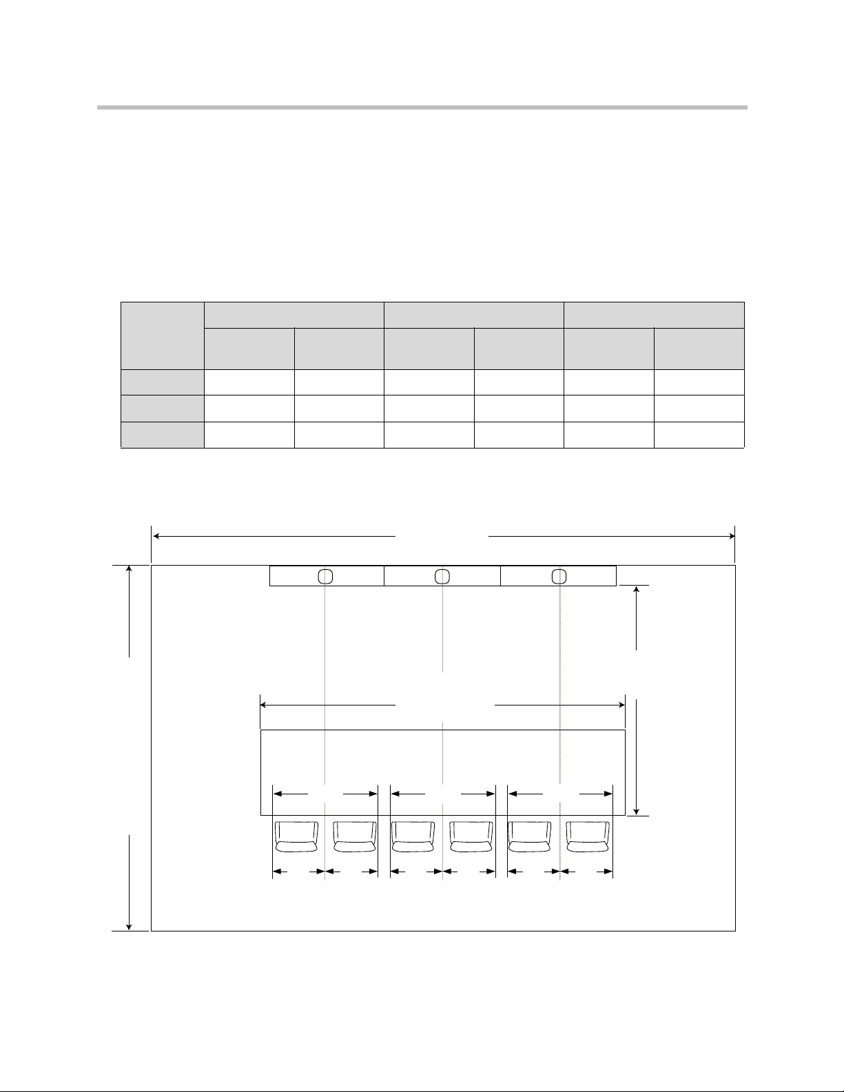
The following table lists the minimum and recommended room width, room
depth, and ceiling height for an ATX 200, ATX 300, or ATX 400 room.
Room Width Room Depth Ceiling Height
Minimum
Recom-
mended Minimum
Recom-
mended Minimum
Recom-
mended
ATX 200 18’ (5.5 m) 24’ (7.3 m) 13’ 6” (4.1 m) 15’ (4.6 m) 8’ (2.4 m) 8’ 8” (2.7 m)
ATX 300 23’ (7 m) 29’ (8.8 m) 13’ 6” (4.1 m) 15’ (4.6 m) 8’ (2.4 m) 8’ 8” (2.7 m)
ATX 400 28’ (8.5 m) 34’ (10.4 m) 13’ 6” (4.1 m) 15’ (4.6 m) 8’ (2.4 m) 8’ 8” (2.7 m)
Figure 2-1 shows the width, depth, height, and additional room dimensions.
Figure 2-1 ATX Room Dimensions
2 - 2 Polycom, Inc.
Page 17

Installing the Displays, Table, Cameras, and Chairs
Selecting the Displays and Table
The list below provides the basic information you need when choosing your
displays and table. Following these guidelines will enable you to create a
lifelike immersive telepresence experience. However, you may decide to make
changes depending on your particular situation:
• The displays should be between 58" to 65" in diagonal size.
• Each display must have an HDMI input.
• Each display must be able to go into Sleep or Standby mode when no
video is received. Additionally, each display must be able to wake up from
Sleep or Standby mode when video is received.
• The displays must be able to support 1920 x 1080 resolution @ 60Hz
without overscan or underscan.
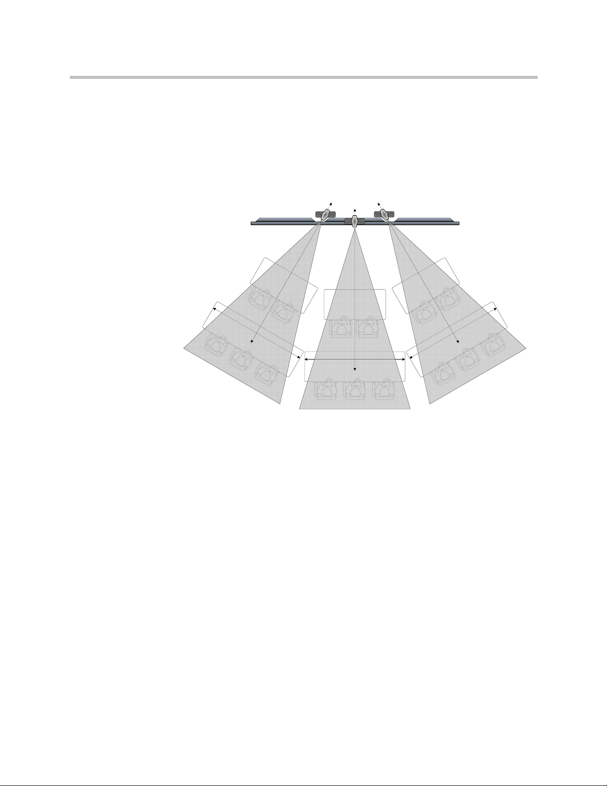
• The table must be rectangular.
Note that you can use more than one rectangular table and set them up in
a non-rectangular seating arrangement as shown in Figure 2-3.
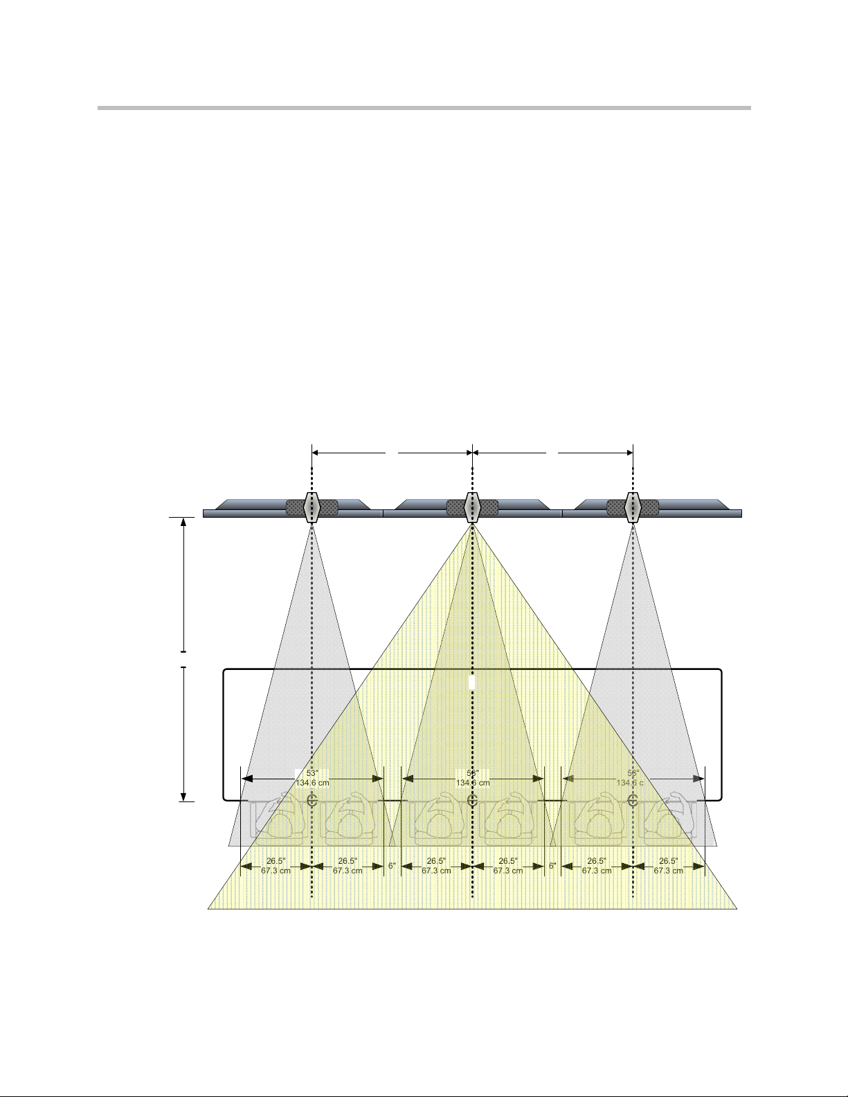
• As shown in Figure 2-1, the table width required to capture two people is
53" (134.6 cm). The space between the cameras should be between 3" (7.6
cm) and 6" (15.2 cm).
• As shown in Figure 2-1, the table must have a minimum width of 115"
(292.1 cm) for ATX 200 rooms, 171" (434.3 cm) for ATX 300 rooms, and 227"
(576.6 cm) for ATX 400 rooms.
• If you choose to add content display(s), Polycom recommends selecting
LCDs. You can select plasma displays, but they are subject to burn-in from
the Polycom logo that appears when content is not being shared (if that
option is selected). If you do choose plasma displays, be sure to power off
the content displays when they are not being used.
Note that these guidelines do not apply to ATX SDK solutions. They should be
adjusted to fit your room size, table shape, and seating arrangement.
Polycom, Inc. 2 - 3
Page 18
53"
134.6 cm
26.5"
67.3 cm
26.5"
67.3 cm
6" 6"
59"
C
59"
53"
134.6 cm
26.5"
67.3 cm
26.5"
67.3 cm
CC
110"
53"
134.6 cm
26.5"
67.3 cm
26.5"
67.3 cm
b
Polycom ATX Integrator’s Guide
Determining the Placement of the Displays and Table
To properly align the cameras, you should correctly place the displays and
table relative to each other. These are the guidelines you should follow:
• The displays must be mounted on a wall so that they are horizontally
aligned and positioned next to each other with no space between the
bezels.
• The displays must be mounted so that the bottom edge of the active video
on the displays is at the same height as the tabletop. For example, if the
tabletop is 30" (76.2 cm) high and the displays have a 2" (5.1 cm) bottom
bezel, then the displays must be mounted so that their bottom edge is 28"
(71.1 cm) from the floor.
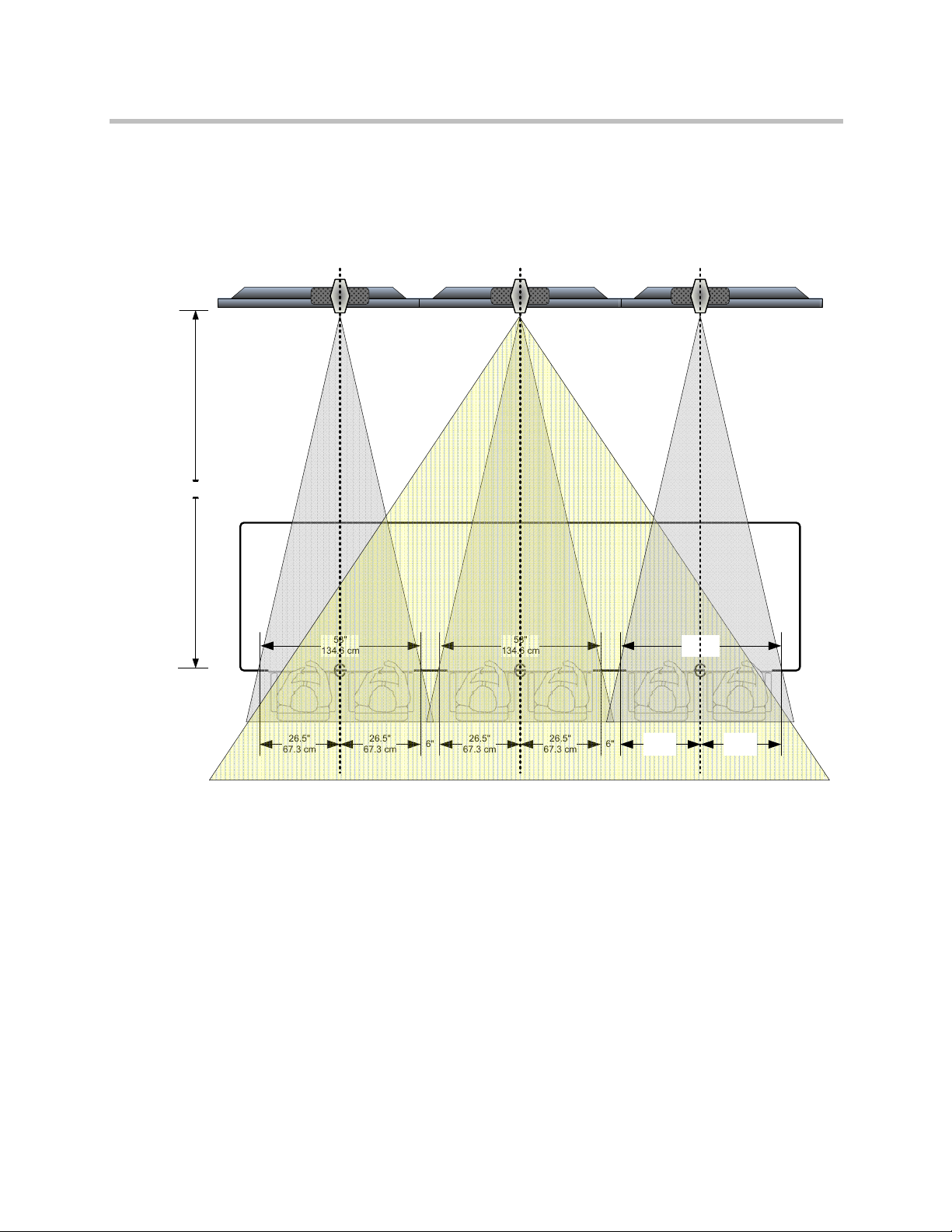
• The distance from the rear edge of the table to the front of the displays
should be 110" (279.4 cm). Figure 2-2 shows the fields of view from the
cameras when the table is placed at this distance in an ATX 300 room. Note
that the center camera does not capture all the participants completely.
2 - 4 Polycom, Inc.
Figure 2-2 Camera Fields of View with a Table Placed at 110" (279.4 cm)
(Top View) - ATX 300 Example
Page 19
C
C
C
Installing the Displays, Table, Cameras, and Chairs
• The table must be centered with the vertical center of the middle display.
• For non-rectangular seating arrangements, you need to provide the
vertical and horizontal fields of view along with the table size into a CAD
package. The target is for the sight line to be perpendicular to the table
edge and to the people in the room.
Note that the camera line of sight is perpendicular and intersects the tables
at their mid point.
Figure 2-3 Camera Fields of View with Non-Rectangular Seating Arrangement
(Top View) - ATX 300 Example
Polycom, Inc. 2 - 5
Page 20
Polycom ATX Integrator’s Guide
6" 6"
C
53"
134.6 cm
26.5"
67.3 cm
26.5"
67.3 cm
CC
126"
53"
134.6 cm
26.5"
67.3 cm
26.5"
67.3 cm
53"
134.6 cm
26.5"
67.3 cm
26.5"
67.3 cm
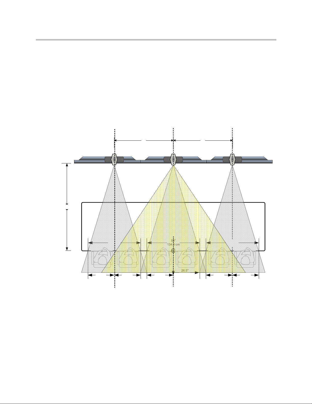
For ATX 300 only, if the room is large, you can choose to place the table farther
than 110" (279.4 cm). By moving the table out to 126" (320 cm), you will be able
to completely see Seats 1 through 6 when the center camera zooms out for the
full room view, as shown in Figure 2-4. Note, however, that by moving the
table farther than 110" (279.4 cm), the participants will appear somewhat
farther from view on the far end of the conference.
Figure 2-4 Camera Fields of View with a Table Placed at 126" (320 cm) (Top View) -
ATX 300 Example
2 - 6 Polycom, Inc.
Page 21
6" 6"
59"
C
53"
134.6 cm
26.5"
67.3 cm
26.5"
67.3 cm
53"
134.6 cm
26.5"
67.3 cm
26.5"
67.3 cm
53"
134.6 cm
26.5"
67.3 cm
26.5"
67.3 cm
CC
105"
59"
Installing the Displays, Table, Cameras, and Chairs
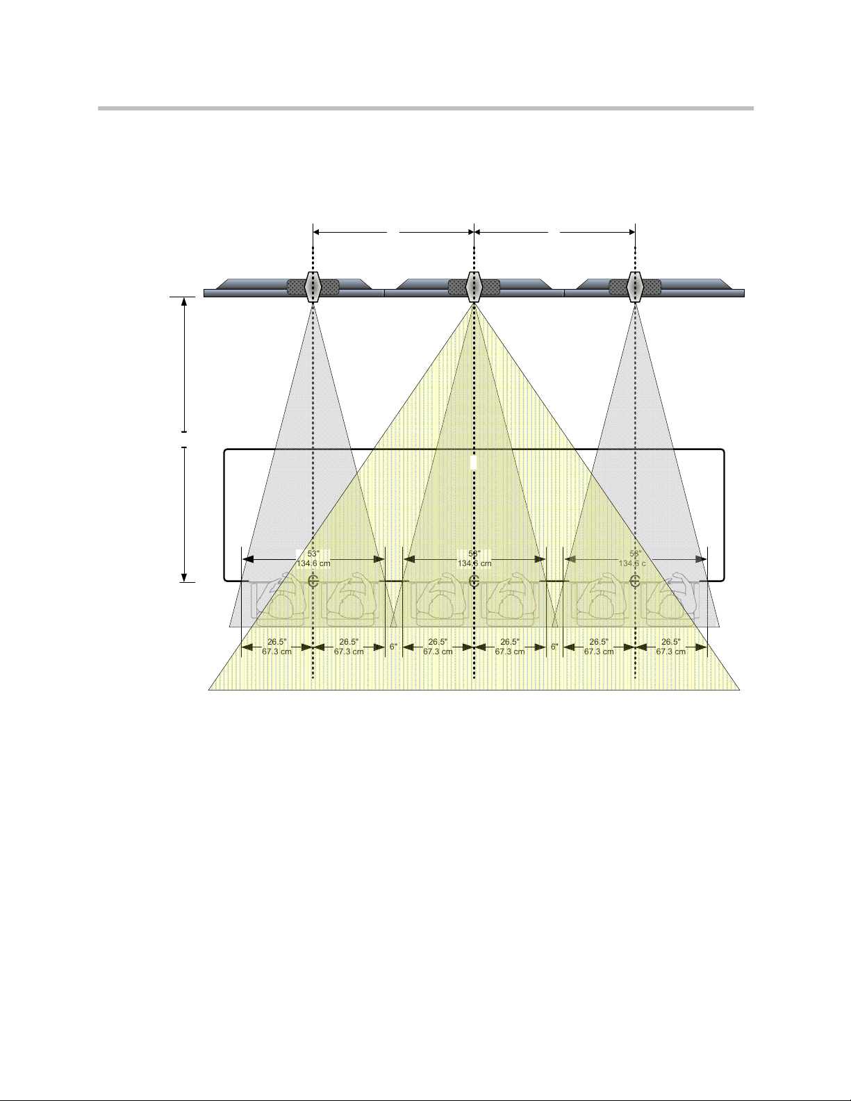
• If, due to room restrictions, you must position the table closer than 110"
(279.4 cm), the field of views will widen and, therefore, overlap more than
normal. Figure 2-5 shows the overlap in an ATX 300 room. This increases
the likelihood of a person appearing on two displays at the same time. For
example, if a person seated at Seat 2 backs up or moves to his/her right,
the people at the far end will see that person on two displays at the same
time. If you move the table as close as 84" (213.4 cm), Seats 2 through 5 may
not appear completely on camera in calls in which only one camera is used
to capture Seats 2 through 5.
Note that placing the table closer than 110” will prevent the camera from
capturing the outside participants.
Figure 2-5 Camera Fields of View with a Table Placed Closer Than 110" (279.4 cm)
(Top View) - ATX 300 Example
Polycom, Inc. 2 - 7
Page 22
Center DisplayLeft Display Right Display
C
L
110" [2.79 m]
Displays and Table
Centerline
180" [4.57 m] minimum
Polycom ATX Integrator’s Guide
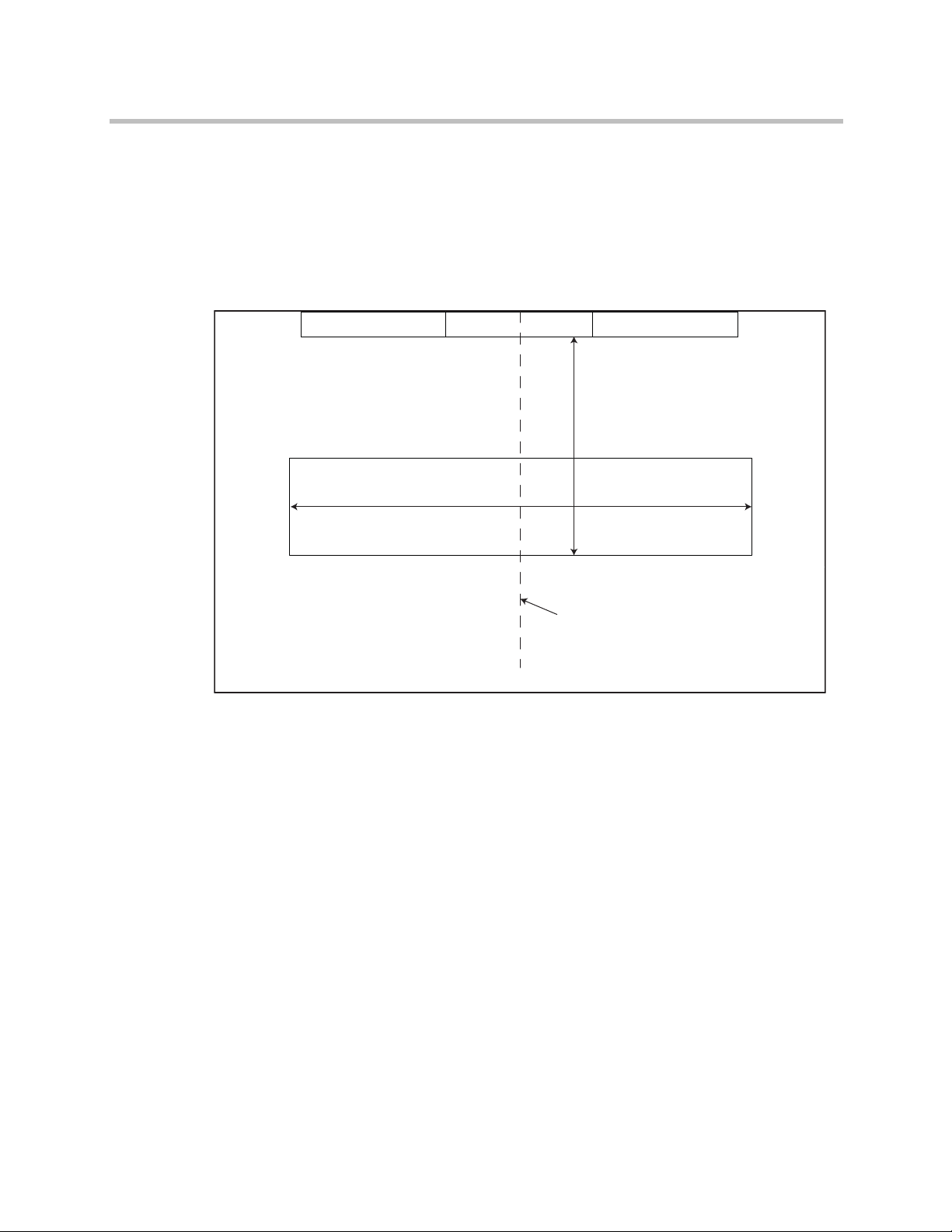
Installing the Displays and Table
Once you have determined where to place the displays, you can install them
on the wall. After installing the displays, place the rear edge of the table 110"
(279.4 cm) from the front of the displays. The table should be parallel to the
displays and the centerline of the table should align with the centerline of the
displays as shown in Figure 2-6.
Figure 2-6 Placing the Table Relative to the Displays
(Top View) in an ATX 300 Room
Installing the Cameras
The ATX comes equipped with Polycom EagleEye™ 1080p cameras. When
installing the cameras, you must center one camera above each display. You
can either attach the cameras to the wall above the displays or you can install
the cameras on top of the displays; however, Polycom highly recommends
attaching the cameras to the wall. By doing so, the cameras are less likely to
become misaligned if the displays get bumped.
Whether you are planning to install the cameras on the wall or on top of the
displays, you must first attach them to the Polycom EagleEye 1080p shelf (part
number 2215-24143-001). For information about how to attach the cameras to
the shelf and how to mount the shelf to the wall or to the displays, refer to the
Setting up the Polycom EagleEye 1080p Shelf document (part number
1725-28622-002) provided with the shelf.
2 - 8 Polycom, Inc.
Page 23
53"
134.6 cm
26.5"
67.3 cm
26.5"
67.3 cm
6" 6"
59"
C
59"
53"
134.6 cm
26.5"
67.3 cm
26.5"
67.3 cm
CC
110"
53"
134.6 cm
26.5"
67.3 cm
26.5"
67.3 cm
b
Installing the Displays, Table, Cameras, and Chairs
The camera should be placed on the center of the captured image rather than
the center of the display as shown in Figure 2-7. This makes the camera line of
sight perpendicular to the table edge.
Figure 2-7 Placing the Cameras - ATX 300 Example
Polycom, Inc. 2 - 9
Page 24
26.5"
67.3 cm
26.5"
67.3 cm
6" 6"
59"
C
59"
26.5"
67.3 cm
26.5"
67.3 cm
CC
26.5"
67.3 cm
26.5"
67.3 cm
26.5"
67.3 cm
26.5"
67.3 cm
59"
Camera
Alignment
Marks
Camera
Alignment
Marks
Camera
Alignment
Marks
Camera
Alignment
Marks
Camera
Alignment
Marks
6"
Polycom ATX Integrator’s Guide
Creating the Camera Alignment Marks
To create the camera alignment marks:
1 Ensure that the vertical centerline of the table aligns with the vertical
centerline of the middle display as shown in Figure 2-6.
2 Determine the table length required to capture two people on camera in
seating positions. The recommended width is 53" (134.6 cm).
3 Determine the separation distance between the captured field of view.
The recommended distance is 6" (15.2 cm).
Keep in mind that the wider the distance, the further it takes before the
cameras’ field of views overlap.
4 Adhere painter’s tape to the top of the table to create the camera
alignment marks as shown in Figure 2-8.
Note that all the cameras are normalized to the same width so that they all
have the same scaled factor.
Figure 2-8 Creatin g the Camera Alignment Marks
(Top View)
2 - 10 Polycom, Inc.
Page 25

Installing the Displays, Table, Cameras, and Chairs
Placing the Chairs
As shown in Figure 2-2, where a conference participant is seated affects where
and how they appear on the displays at the far site. To ensure that the
conference participants appear on the displays, but that they do not appear on
more than one display, you should place the chairs at the proper locations at
the table and mark those locations.
To help participants keep their chairs at the proper locations at the table,
Polycom recommends that you use one or more of the following visual or
physical markers:
• Place placemats on the tabletop at each of the proper chair locations.
• Mark the tabletop or the floor to indicate where the chairs should be
positioned.
• Attach barriers under the table so that the participants cannot physically
move their chairs to an incorrect location.
Additionally, the chairs you select must not exceed the following dimensions:
• Arm span: 24½" (62.2 cm)
• Wheel base: 27" (68.6 cm)
Polycom, Inc. 2 - 11
Page 26

Polycom ATX Integrator’s Guide
2 - 12 Polycom, Inc.
Page 27

Installing the Remaining Electronic Components
Now that you have installed the displays, table, cameras, and chairs, you can
install the remaining electronic components, which may include:
• Polycom HDX codecs and, if needed, HDX 2U rack mounting trays
3
• Touch Panel controller, C2ENET-1 Ethernet interface expansion card (may
not be needed for ATX SDK version 2.0), and mounting ears for the Touch
Panel controller
• Speakers and, if needed, speaker mounts
• Three Polycom Ceiling Microphone Arrays
• Touch Panel
• The Touch Panel TPS-IMPC interface module, which is typically used with
a wired Touch Panel only (may not be needed for ATX SDK version 2.0)
• Cables for all the components
• Polycom ATX 200/300/400 System Wiring Specification (part number
3823-30099-002)
Installing the Codecs and the Touch Panel Controller
The integrator is responsible for determining where to place the Polycom
codecs and the Touch Panel controller. In most cases, the codecs and the Touch
Panel controller will be installed in a rack. If so, perform the following steps.
Note that this is optional if you are using the ATX SDK version.
Polycom, Inc. 3 - 1
Page 28

Polycom ATX Integrator’s Guide
To prepare the codecs and the Touch Panel controller for installation in a rack:
1 Attach each codec to an HDX 2U rack mounting tray (part number
2215-28283-001) using the hardware supplied with the trays.
For more information, refer to the Setting up the Polycom HDX 2U Rack
Mounting Solution document (part number 1725-28249-001).
2 Install the codecs in the rack.
3 Install the C2ENET-1 Ethernet interface expansion card in the Touch
Panel controller, as described in the installation guide supplied with the
card (may not be needed for ATX SDK version 2.0).
4 Attach the mounting ears to the Touch Panel controller using the
hardware supplied with the Touch Panel controller.
For more information, refer to the documentation supplied with the Touch
Panel controller.
5 Install the Touch Panel controller in the rack.
Installing the Speakers
You must connect speakers to the ATX in order to hear audio. You can provide
your own speakers; however, Polycom recommends using the Polycom Stereo
Speaker kit, which provides excellent volume and rich sound in large rooms.
The Polycom Stereo Speaker kit includes two speakers as well as a subwoofer.
If you choose to provide your own speakers, the speakers should be equivalent
to the speakers provided with the StereoSurround kit. For more information
about the Polycom Stereo Speaker kit, refer to http://www.polycom.com.
To attach the speakers to the wall near the displays, Polycom recommends
using Omnimount universal speaker mounting brackets or an equivalent
mounting bracket.
To install the speakers:
1 Install one speaker mounting bracket on the wall to the left of the
displays and one on the wall to the right of the displays by following the
directions in the documentation provided with the mounting brackets.
Install the brackets so that the speakers will be centered as much as
possible with the side of the displays as shown in Figure 3-1.
2 Attach one speaker to each mounting bracket.
3 For better audio projection, angle the speakers 40 degrees inwards
towards the center of the table.
3 - 2 Polycom, Inc.
Page 29

Floor
Speaker Speaker
Installing the Remaining Electronic Components
Figure 3-1 Installing the Speakers in an ATX 300 Room
4 Place the subwoofer along the same wall as the displays or in a corner
near the displays.
Installing the Microphones
Polycom highly recommends installing three Ceiling Microphone Arrays in
the ATX room whether you have an ATX 200, 300, or 400 room. However, if
the Ceiling Microphone Arrays cannot be installed, optional Polycom HDX
tabletop microphones can be installed instead. For information about
installing these optional tabletop microphones, see Installing the Tabletop
Microphones on page 3-10.
Installing the Ceiling Microphone Arrays
Before you begin, check the height of the ceiling in the ATX room. If the ceiling
is 10’ (3.05 m) or higher, you will need an optional 6’ (1.82 m) drop cable for
each Ceiling Microphone Array. To ensure that you are using the correct cable,
verify that the number of pins on the cable connector matches the number of
pins on the connector on the electronics enclosure.
To install the Ceiling Microphone Arrays:
1 Determine where you will place the three Ceiling Microphone Arrays in
the room:
— Center Ceiling Microphone Array: The center Ceiling Microphone
Array should be no more than 6" (15.2 cm) from the vertical and
horizontal centerline of the table.
Polycom, Inc. 3 - 3
Page 30

Polycom ATX Integrator’s Guide
Two, Three, or Four Displays
Locate Ceiling Mics
7' (2.13 m) Above Floor
C
L
6' (182 cm) +/-3" (7 cm)
Displays and Table
Center Line
C
L
Orient Dot on Ceiling Mics
to Face Wall Behind Displays
Center Ceiling Mic
(ATX 200, ATX 300, and ATX 400)
Left Ceiling Mic
(ATX 400)
Left Ceiling Mic
(ATX 300)
Left Ceiling Mic
(ATX 200)
Right Ceiling
Mic (ATX 400)
Right Ceiling
Mic (ATX 300)
Right Ceiling
Mic (ATX 200)
6' (182 cm) +/-3" (7 cm)
7' (213 cm) +/-3" (7 cm)
7' (213 cm) +/-3" (7 cm)
8' (243 cm) +/-3" (7 cm) 8' (243 cm) +/-3" (7 cm)
— Left and right Ceiling Microphone Arrays:
» For the ATX 200: The left and right Ceiling Microphone Arrays
should be 6’ (18 cm) +/-3" (7 cm) from the center line of the
displays and table.
» For the ATX 300: The left and right Ceiling Microphone Arrays
should be placed 7’ (213 cm) +/-3" (7 cm) from the center line of
the displays and table.
» For the ATX 400: The left and right Ceiling Microphone Arrays
should be placed 8’ (243 cm) +/-3" (7 cm) from the center line of
the displays and table.
Note that these locations may need to vary slightly due to the placement
of light fixtures or other obstacles in the ceiling.
2 Connect a 2’ (61 cm) drop cable to the bottom of each electronics
enclosure.
Figure 3-2 Ceiling Microphone Array Placement
To ensure that you are using the correct cable, verify that the number of
pins on the cable connector matches the number of pins on the connector
on the electronics enclosure.
3 - 4 Polycom, Inc.
Page 31

Installing the Remaining Electronic Components
Figure 3-3 Attaching the Drop Cable to the Electronics Enclosure
3 If the ceiling is suspended, skip this step and continue with step 4. If the
ceiling is not suspended, attach the electronics enclosure to the ceiling
using suitable hardware for the ceiling type. Align the electronics
enclosure so that, when the microphone ball is attached, the dot on the
ball points straight towards the wall behind the credenza as described in
step 9.
Use caution when climbing a ladder to attach the electronics enclosure.
Figure 3-4 Attaching the Electronics Enclosure to a Ceiling that is Not Suspended
Continue with step 5.
Polycom, Inc. 3 - 5
Page 32

Polycom ATX Integrator’s Guide
.75” (1.9 cm)
4 If the ceiling is suspended:
a Remove a ceiling tile from the drop ceiling in the three locations where
you will be installing a Ceiling Microphone Array.
Use caution when climbing a ladder to remove the ceiling tiles.
b Cut a .75" (2 cm) hole in each ceiling tile that you removed.
Figure 3-5 Cutting the Ceiling Tile for the Ceiling Microphone Array
c Insert a bushing into the hole in each of the ceiling tiles.
Figure 3-6 Inserting the Bushing into the Ceiling Tile
d Place an electronics enclosure on each ceiling tile, making sure that the
drop cable drops through the hole in the tile, and then place each
ceiling tile back into the ceiling.
Use caution when climbing a ladder to replace the ceiling tiles.
3 - 6 Polycom, Inc.
Page 33

25’ (7.6 m) cable
Installing the Remaining Electronic Components
Figure 3-7 Placing the Ceiling Tile Back into the Ceiling
e For added safety when removing the ceiling tiles at a later time,
securely attach the electronics enclosure to the ceiling supports using
wire or other hardware appropriate for your ceiling type and in
accordance with local regulations.
If you use wire to secure the electronics enclosure, be sure that the
length of the wire is short enough to prevent the enclosure from
striking a person removing the ceiling tiles.
5 Connect the cables:
a Connect one end of a 25’ (7.6 m) plenum crossover cable to the center
electronics enclosure, and connect the other end to the electronics
enclosure on the right (when facing the credenza).
Figure 3-8 Connecting the Cables
Polycom, Inc. 3 - 7
Page 34

Polycom ATX Integrator’s Guide
b Connect one end of a 25’ (7.6 m) plenum crossover cable to the
electronics enclosure on the right, and connect the other end to the
electronics enclosure on the left.
c Connect one end of a 50’ (15.2 m) plenum crossover cable to the
electronics enclosure on the left, and then run the cable through the
conduit in the wall behind the credenza and down to the junction box.
(This conduit and junction box should have been previously installed
by an electrician.)
d Pull the end of the 50’ (15.2 m) cable through the junction box and
connect it to the back of the wall plate provided in the Ceiling
Microphone Array kit.
6 Attach the wall plate to the junction box using two 6-32 oval head screws.
Note that these screws are provided with the ATX; they are not included
in the bag with the wall plate.
Figure 3-9 Attaching the Wall Plate and Connecting the 10’ (3.1 m) Cable
7 Connect one end of the 10’ (3.1 m) non-plenum straight-through cable to
the wall plate, and connect the other end to the Primary codec.
3 - 8 Polycom, Inc.
Page 35

Installing the Remaining Electronic Components
8 Connect a microphone ball to each drop cable.
Ensure that the microphone balls are located approximately 7’ (2.13 m)
above the floor. If the ceiling is 10’ (3.05 m) or higher, the microphone balls
are typically too high. In such cases, you must use an optional 6’ (1.82 m)
drop cable for each Ceiling Microphone Array.
Figure 3-10 Attaching the Ceiling Microphone Ball
9 Point the dot, which is located on the band around the middle of the
microphone ball, straight towards the wall behind the displays.
Inside the microphone ball are three hypercardioid microphones. In
stereo, the microphone that is aligned with the dot is dead, and only the
remaining two microphones are active. For this reason, you can achieve
the best performance of the echo canceller and the best audio pickup of the
participants by rotating the ball so that the dot points towards the wall
behind the displays.
Figure 3-11 Aligning the Dot on the Ceiling Microphone Ball
Polycom, Inc. 3 - 9
Page 36

Polycom ATX Integrator’s Guide
Note: Wiring is shown with the microphones connected
to the right c-link2 port. The Polycom logo on the microphones
must be pointed away from the displays.
To Codec
Center DisplayLeft Display Right Display
Installing the Tabletop Microphones
If the Ceiling Microphone Arrays cannot be installed in the ATX room, you can
install optional HDX tabletop microphones instead.
To install the tabletop microphones, you must have three HDX tabletop
microphone array kits. Each kit contains one microphone array and one
25-foot (7.62 m) cable. If you need a longer cable to reach the codec, you can
order a 50-foot (15.24 m) cable from Polycom.
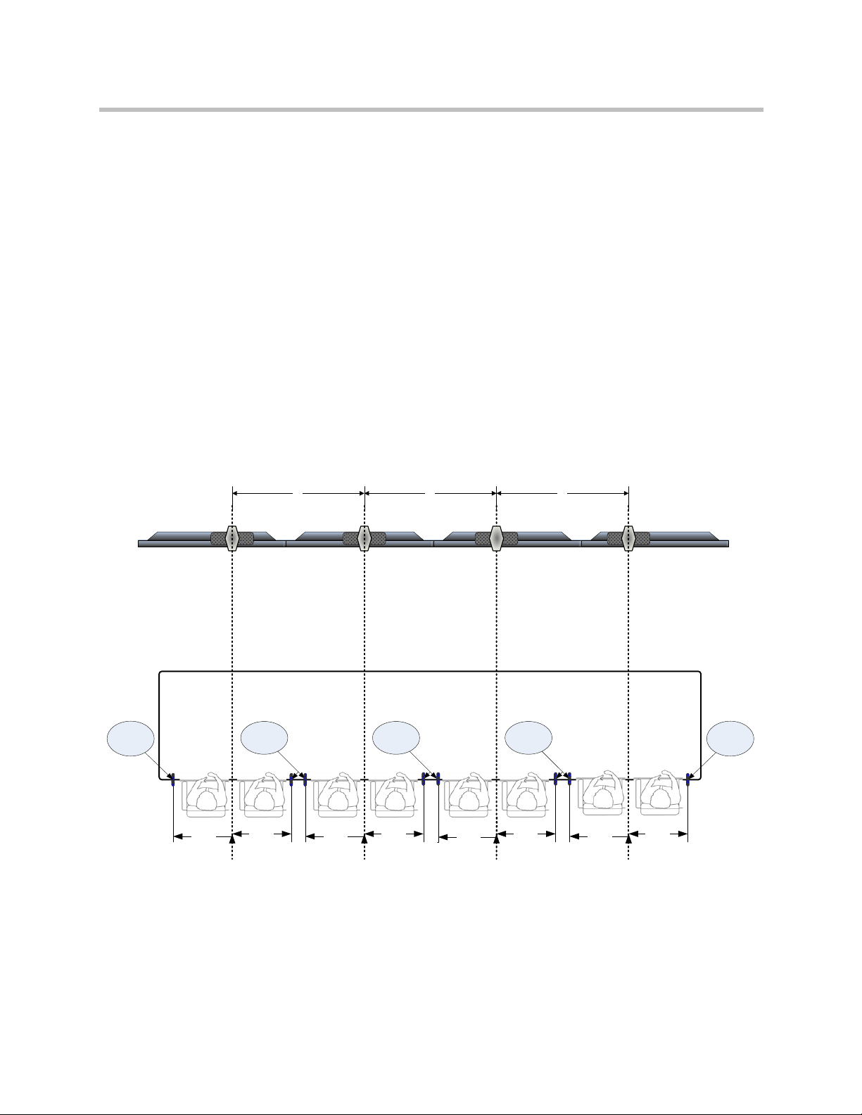
The illustration below shows the tabletop microphone setup in an ATX 300
room.
Figure 3-12 Tabletop Microphone Placement (Top View)
When you install tabletop microphones, you should place them on the table in
the positions shown in Figure 3-12. Make sure that the Polycom logo on each
microphone points away from the displays as shown in Figure 3-13. To
achieve the best imaging, you should keep the microphones from rotating out
of position. To do so, you may want to consider detenting the microphones.
Additionally, you may want to add holes or channels to the table to hide the
cables.
3 - 10 Polycom, Inc.
Page 37

Installing the Remaining Electronic Components
Figure 3-13 Tabletop Microphone Orientation
Installing the Touch Panel
To in s ta ll t he To uc h P a ne l:
1 Place the Touch Panel on the table.
2 For wired panels using an interface module, place the TPS-IMPC module
in a location where the cable from the Touch Panel can easily reach it. Be
sure to leave enough slack on the Touch Panel side of the cable so that
users can easily move the Touch Panel to a comfortable position on the
table. Note that this may not be needed for ATX SDK version 2.0.
Attaching the Serial Number Label
A serial number label is supplied with each ATX system.
The ATX Warranty and Service Maintenance Agreement is determined by this
unique serial number, which applies to the complete list of Polycom
components shipped with the ATX. This single serial number also enables
Support to keep track of issues related to the particular ATX. Therefore, all of
the Polycom components shipped with the ATX must remain together. Do not
swap out individual components, such as one codec or one camera, without
authorization.
Polycom, Inc. 3 - 11
Page 38

Polycom ATX Integrator’s Guide
When you attach the serial number label, it is important to adhere it where it will be
easily accessible and will not get discarded. Polycom suggests that you adhere the
label to equipment that will permanently reside with the ATX, such as the
electronics rack. Do not adhere the label to an individual component, such as a
codec, because if that component needs to be replaced, the label may be lost.
Connecting the Cables
At this point in the installation, connect the cables to the ATX components
according to your own wiring configuration. Polycom provides the Polycom
ATX 200/300/400 System Wiring Specification (part number 3823-30099-002)
with each ATX as a sample configuration.
This sample configuration shows a serial interface between the control system and
all three codecs. However, for an ATX SDK version 2.0, you only need a serial
interface between the Primary (Master) codec and the control system.
3 - 12 Polycom, Inc.
Page 39

Configuring the Polycom ATX
This chapter describes the steps you must take to configure the ATX.
Do not proceed with the configuration procedures in this chapter until you have
wired the ATX. For a sample wiring configuration, refer to the Polycom ATX
200/300/400 System Wiring Specification (part number 3823-30099-002).
4
Before you begin configuring the ATX, make sure that:
• The room is ready:
— The displays and cameras are installed correctly.
— The table is positioned correctly and the camera alignment marks
have been created on the table.
— The codecs are installed and the cables are connected.
• You have a laptop with:
— A LAN connection in the room.
— .NET Framework version 2.0 or later installed.
— Windows XP SP3, or Windows Vista Business/Enterprise/Ultimate
SP2 installed.
— Serial cable (for loading the Touch Panel controller).
— Null modem cable (for configuring the codec).
Polycom, Inc. 4 - 1
Page 40

Press to backspace
or delete
Press to select or
accept
Polycom ATX Integrator’s Guide
Performing the HDX Out-of-Box Setup
To perform the HDX out-of-box setup:
1 Power on the displays.
2 Power on all of the HDX codecs.
3 Connect the null modem serial cable from the laptop to the COMM1
connector on one of the codecs.
4 From the Start menu on the laptop, select Programs, select Polycom
Telepresence Tool 2.7, and then select HDX Soft Remote.
Figure 4-1 HDX Soft Remote
5 From the pull-down box at the top left of the HDX Soft Remote, select the
laptop COM port that is connected to the Primary codec. Note that this
guide uses Primary, Secondary, Left, and Right to describe the codecs.
4 - 2 Polycom, Inc.
Page 41

Configuring the Polycom ATX
For ATX SDK version 2.0, the codecs are typically described as Master
and Slaves; however, only the terms Primary, Secondary, Left, and Right
are used in this guide.
A second box appears to the right of the first box on the HDX Soft Remote.
6 Select 9600 as the baud rate and click Go.
Once the laptop is connected, the boxes will turn gray and the text on the
Go button will change to Stop.
7 Click Set DVI Mon.
The output settings will change and the setup wizard will appear on the
ATX displays. (In order for the wizard to appear on the displays, the
displays must be able to handle 1024 x 768 display resolution.)
8 Complete the setup wizard:
a Select American English.
b Select the country where the system will be installed (United States is
the default).
c For the System Name, as an example for an ATX 300 room, enter
HDX1, HDX2, or HDX3. Alternatively, you can enter more specific
names if requested by the customer.
d For the LAN Properties, select the following:
» IP Address: Specify or Automatic (should be determined by the
customer’s system administrator).
Polycom recommends selecting Specify and then entering the IP
address and the LAN settings at this point in the installation.
To insert the periods into the IP address, press the right arrow
button on the HDX Soft Remote.
Figure 4-2 HDX Soft Remote Right Arrow Button
» Connect to LAN: Yes
Polycom, Inc. 4 - 3
Page 42

Polycom ATX Integrator’s Guide
» Allow IP calls: Yes
» Enable EAP/802.1X: Leave the check box unchecked.
» Enable 802.1p/Q: Leave the check box unchecked.
» Enable PC LAN Port: Leave the check box unchecked.
e For Security, select the following:
» Security mode: Leave the check box unchecked.
» Room Password: Using the Backspace button on the HDX Soft
Remote, delete the serial number, which appears on the screen as
asterisks.
» Require Login for System Access: Leave the check box unchecked.
f For Registration, select the following:
» Name: Do not change the name; it should be the same as on the
previous page.
» Email address: Do not enter an email address.
» Register: Clear the check box.
9 Check that the date and time is correctly set (all the codecs should have
the same date and time). For more information on how to set the date and
time, refer to the Administrator’s Guide for Polycom HDX Systems available
at http://www.polycom.com/support/video/index.html.
10 Repeat steps 3 through 9 for the remaining codecs.
Upgrading and Activating the HDX Software
To upgrade and activate the HDX software:
1 Download either the HDX software for ATX SDK version 2.0 or the HDX
software for ATX 300 version 2.7:
a Go to the Polycom website (http://www.polycom.com).
b Go to Support > ATX 300.
c In the Downloads section, click on the ATX 300 v2.7 link to download
the software for ATX 300 version 2.7 or click on the ATX SDK v2.0 link
to download the software for ATX SDK version 2.0.
IMPORTANT: The HDX software for ATX SDK version 2.0 is different from the HDX
software for ATX version 2.7. You cannot use the HDX software for ATX SDK with
AT X version 2.7 control panel code, so be sure to download the correct software for
your configuration.
4 - 4 Polycom, Inc.
Page 43

Configuring the Polycom ATX
d Save the .zip file to your system and then extract the files in the .zip
file.
2 Collect the license and serial numbers.
3 Obtain option key codes for the software upgrades and options for all
three codecs.
An option key code is the number that activates software or options on a
specific system. Polycom generates a key code when you submit the
license number and system serial number information.
For complete information about obtaining key codes, activating options, and
installing the software, refer to the Installing Polycom HDX Software and Options
document. To access this document, go to
http://www.polycom.com/support/video/index.html, click on any HDX model listed
under the “HDX Series” heading, and then open the document.
4 Install the software:
a For the Primary codec, access the Software Update section of the
Polycom web UI by going to Admin Settings > General Settings.
b Browse to where the HDX software
Begin Update.
For the specific name of the
c Accept all the default choices in the Software Update.
5 When the codec has finished rebooting, go to Admin Settings > General
Settings > Options in the web UI.
6 Enter the option key code in the Key field.
This option key code enables the options that are required for
telepresence.
7 Click Update.
8 Repeat steps 4 through 7 for the remaining codecs.
.pup
.pup
file is located and click
file, refer to the ATX Release Notes.
Performing the Remaining Software Configuration
Refer to the Polycom Immersive Telepresence (ITP) Administrator’s Guide (part
number 3725-26945-003) to:
• Upgrade and configure the control system (Chapter 1)
Because you have already installed the Polycom HDX software, you can
skip over the “Upgrading the Polycom HDX Software” section in Chapter
1 of the Administrator’s Guide and begin instead with the “Upgrading and
Configuring the Control System” section.
Polycom, Inc. 4 - 5
Page 44

Polycom ATX Integrator’s Guide
• Install and use the Telepresence Tool (Chapter 2)
• Configure the ITP features (Chapter 3)
If you are using ATX SDK version 2.0, some of the functionality described in the
Polycom Immersive Telepresence (ITP) Administrator’s Guide (part number
3725-26945-003) may not be available depending upon your system configuration.
Once you have performed the remaining software configuration, refer to
Chapter 5 of this document to complete the ATX installation.
4 - 6 Polycom, Inc.
Page 45

Configuring the Displays and Cameras
Once you have completed the remaining software configuration as described
in the Polycom Immersive Telepresence (ITP) Administrator’s Guide (part number
3725-26945-003), you must finish the ATX installation by:
5
• Configuring the display settings
• Configuring, aligning, and matching the cameras
• Taking light and audio measurements
Configuring the Display Settings
To configure the display settings:
1 Make sure that the Telepresence Tool is launched on the laptop.
Figure 5-1 Telepresence Tool Main Screen (Before Connection) - ATX 400 Example
Polycom, Inc. 5 - 1
Page 46

Polycom ATX Integrator’s Guide
2 If the appropriate model name does not appear on the Main screen, click
Switch Model.
3 Click Connect All to connect to the codecs.
4 Select the Display tab.
The following illustration shows the Display tab for an ATX 400.
Figure 5-2 T elepresence Tool Display Tab - ATX 400 Example
5 Click Display Alignment.
The display alignment pattern appears on the screens.
5 - 2 Polycom, Inc.
Page 47

Configuring the Displays and Cameras
Figure 5-3 Display Alignment Pattern
6 The display alignment pattern should align with the edges of each screen.
If it does not, check the display settings and ensure that the display is set
to a mode (such as dot-by-dot mode) where no scaling is done to the
incoming image.
7 Access the settings for each display and configure the following:
a Set the Standby setting so that the display goes into Standby mode
when no video is received.
Note that the name for this setting varies depending on your brand of
display. Besides Standby, some common names for this setting
include Sleep, Sleep Timer, Power Save, and Power Management.
b If possible, disable all the onscreen menus and alerts (such as “No
Signal” and “Video Input 2”).
c Set the video input as either PAL or NTSC.
» Since the integration time for a PAL system is more than NTSC,
the PAL system cameras gather more light in the room.
» For systems using the optional lighting kit, the IRIS setting
number for a PAL system is lower or has a smaller aperture than
NTSC.
Polycom, Inc. 5 - 3
Page 48

Polycom ATX Integrator’s Guide
d Set the appropriate shutter speed based on the video format and
power frequency as shown in the following table.
Video Format Power Frequency Shutter Speed
NTSC 60Hz 1/60s
PAL 50Hz 1/50s
NTSC 50Hz 1/100s
PAL 60Hz 1/120s
Configuring the Cameras
Aligning the Cameras
Before you begin, make sure that you have physically set up the cameras as
described in Chapter 2.
You should align the cameras to point to particular locations in the room.
These positions are stored as presets in the Polycom HDX codecs. For different
operating modes, the control system will activate the different presets to make
the cameras point to the appropriate location for that operating mode. This
procedure describes how to align the cameras for the different modes, and
how to store those locations into the proper presets. The steps in this section
show the recommended Polycom alignment.
For ATX SDK, the integrator has the option to disable or override these
automatic presets.
Aligning the Cameras in an ATX 200 Room
The ATX 200 has two codecs, two displays, and two cameras. As you are
seated in the room facing the displays, the displays are designated left and
right. Each camera is connected to a particular codec, and each codec is
connected to a particular display as described in the following table.
5 - 4 Polycom, Inc.
Page 49

Left Display Right Display
Cam-1
(B1)
Cam-2
(B2)
1
2
3 4
Configuring the Displays and Cameras
Seating Position
Camera
Camera
Location
Display on
which Video
Appears
Codec
the Camera
Normally Points
to
Camera-1
(B1)
Camera-2
(B2)
Left
display
Right
display
Right display 1 (Primary) 1 and 2
Left display 2 (Secondary) 3 and 4
The ATX 200 table has four seats facing the displays. These seats are numbered
1 through 4, from left to right, as you are facing the displays.
Figure 5-4 Location of Displays and Seats in an ATX 200 Room
As described in Chapter 2, “Installing the Displays, Table, Cameras, and Chairs,”
where a conference participant is seated affects where and how they appear on the
displays at the far site. To ensure that the conference participants appear on the
displays, but do not appear on more than one display, you should place the chairs
at the proper locations at the table and mark those locations.
Polycom, Inc. 5 - 5
Page 50

Polycom ATX Integrator’s Guide
The following table shows how the cameras are positioned differently for
different operating modes. It also indicates how many codecs are in the call.
Number of
Codecs in
the Call
Scenario
Preset
Number
Camera-1
(B1) View
Camera-2 (B2)
View
2 Call ATX 200,
TPX HD
204M, or RPX
HD 200 Series
1 Call stand-
alone video
conferencing
system
2 Multipoint call
(Continuous
Presence)
2 Multipoint call
(VARS)
99 Seats 1 and 2 Seats 3 and 4
97 Seats 1, 2, 3,
and 4
96 Seats 1
through 4
99 Seats 1 and 2 Seats 3 and 4
Points towards
Seats 3 and 4.
Note, however, that
the codec for this
camera is not
connected to the far
site, therefore no
video is sent and the
near site display
remains black.
Seats 1 through 4
Aligning the Cameras in an ATX 300 Room
The ATX 300 has three codecs, three displays, and three cameras. As you are
seated in the room facing the displays, the displays are designated center, left,
and right. Each camera is connected to a particular codec, and each codec is
connected to a particular display as described in the following table.
Seating Position
Display on
Camera
Camera
Camera-1
(B1)
Camera-2
(B2)
Camera-3
(B3)
5 - 6 Polycom, Inc.
Location
Center
display
Right
display
Left
display
which Video
Appears Codec
Center display 1 (Primary) 3 and 4
Left display 2 (Left) 5 and 6
Right display 3 (Right) 1 and 2
the Camera
Normally Points
to
Page 51

Center DisplayLeft Display Right Display
Cam-1
(B1)
Cam-3
(B3)
Cam-2
(B2)
1
2
3 4 5
6
Configuring the Displays and Cameras
Note that this guide uses Primary, Secondary, Left, and Right to describe the
codecs. For ATX SDK version 2.0, the codecs are typically described as Master
and Slaves; however, only the terms Primary, Secondary, Left, and Right are
used in this guide.
The ATX 300 table has six seats facing the displays. These seats are numbered
1 through 6, from left to right, as you are facing the displays.
Figure 5-5 Location of Displays and Seats in an ATX 300 Room
As described in Chapter 2, “Installing the Displays, Table, Cameras, and Chairs,”
where a conference participant is seated affects where and how they appear on the
displays at the far site. To ensure that the conference participants appear on the
displays, but do not appear on more than one display, you should place the chairs
at the proper locations at the table and mark those locations.
The following table shows how the cameras are positioned differently for
different operating modes. It also indicates how many codecs are in the call.
Number of
Codecs in
the Call
Scenario
3 Call ATX
300, TPX
HD 306M,
or RPX HD
400 Series
Preset
Number
99 Seats 3 and 4 Seats 5 and 6 Seats 1 and 2
Camera-1
(B1) View
Camera-2
(B2) View
Camera-3
(B3) View
Polycom, Inc. 5 - 7
Page 52

Polycom ATX Integrator’s Guide
Number of
Codecs in
the Call Scenario
2 RPX HD
200 Series,
TPX HD
204M
Series
1 Call stand-
alone video
conferencing
system
Preset
Number
98 Seats 2
97 Seats 2
Camera-1
(B1) View
through 5 and
a portion of
seats 1 and 6
through 5 and
a portion of
seats 1 and 6
Camera-2
(B2) View
Points towards
Seats 5 and 6.
Note,
however, that
the camera is
disabled and
will not send
video.
Points towards
Seats 5 and 6.
Note,
however, that
the codec for
this camera is
not connected
to the far site,
therefore no
video is sent
and the near
site display
remains black.
Camera-3
(B3) View
Points towards
Seats 1 and 2.
Note, however,
that the codec
for this camera
is not connected
to the far site,
therefore no
video is sent
and the near
site display
remains black.
Points towards
Seats 1 and 2.
Note, however,
that the codec
for this camera
is not connected
to the far site,
therefore no
video is sent
and the near
site display
remains black.
3 Multipoint
call
(Continuous
Presence)
3 Multipoint
call (VARS)
96 Seats 2
through 5 and
a portion of
seats 1 and 6
(Note that only one of these three camera views will
be seen at each of the far sites.)
99 Seats 3 and 4 Seats 5 and 6 Seats 1 and 2
Seats 2
through 5 and
a portion of
seats 1 and 6
Seats 2 through
5 and a portion
of seats 1 and 6
Aligning the Cameras in an ATX 400 Room
The ATX 400 has four codecs, four displays, and four cameras. As you are
seated in the room facing the displays, the displays are designated outer left,
center left, center right, and outer right. Each camera is connected to a
particular codec, and each codec is connected to a particular display as
described in the following table.
5 - 8 Polycom, Inc.
Page 53

Center Left DisplayOuter Left Display Center Right Display
Cam-1
(B1)
Cam-3
(B3)
Cam-2
(B2)
1
2
3 4 5
6
7
8
Outer Right Display
Cam-4
(B4)
Configuring the Displays and Cameras
Seating Position
Camera
Camera
Location
Display on
which Video
Appears
Codec
the Camera
Normally Points
to
Camera-3
(B3)
Camera-2
(B2)
Outer left
display
Center
right
Outer right
display
Center left
display
3 (Right) 1 and 2
2 (Secondary) 5 and 6
display
Camera-1
(B1)
Camera-4
(B4)
Center left
display
Outer right
display
Center right
display
Outer left
display
1 (Primary) 3 and 4
4 (Left) 7 and 8
The ATX 400 table has eight seats facing the displays. These seats are
numbered 1 through 8, from left to right, as you are facing the displays.
Figure 5-6 Location of Displays and Seats in an ATX 400 Room
As described in Chapter 2, “Installing the Displays, Table, Cameras, and Chairs,”
Polycom, Inc. 5 - 9
where a conference participant is seated affects where and how they appear on the
displays at the far site. To ensure that the conference participants appear on the
displays, but do not appear on more than one display, you should place the chairs
at the proper locations at the table and mark those locations.
Page 54

Polycom ATX Integrator’s Guide
The following table shows how the cameras are positioned differently for
different operating modes. It also indicates how many codecs are in the call.
Number of
Codecs in
the Call
4Call ATX
3Call ATX
2Call RPX
Scenario
400 or RPX
HD 400
Series
300 or TPX
HD 306M
Series
HD 200
Series, TPX
HD 204M
Series, or
ATX 200
Preset
Number
99 Seats 3 and 4 Seats 5 and 6 Seats 1 and 2 Seats 7 and 8
95 Seats 1
94 Seats 1
Camera-1
(B1) View
through 4
through 4
Camera-2
(B2) View
Seats 5
through 8
Seats 5
through 8
Camera-3
(B3) View
Points towards
Seats 1 and 2.
Note,
however, that
the camera is
disabled and
will not send
video.
Points towards
Seats 1 and 2.
Note,
however, that
the codec for
this camera is
not connected
to the far site,
therefore no
video is sent
and the near
site display
remains black.
Camera-4
(B4) View
Points towards
Seats 7 and 8.
Note,
however, that
the codec for
this camera is
not connected
to the far site,
therefore no
video is sent
and the near
site display
remains black.
Points towards
Seats 7 and 8.
Note,
however, that
the codec for
this camera is
not connected
to the far site,
therefore no
video is sent
and the near
site display
remains black.
5 - 10 Polycom, Inc.
Page 55

Configuring the Displays and Cameras
Number of
Codecs in
the Call Scenario
1 Call stand-
alone video
conferencing
system
4 Multipoint
call
(Continuous
Presence
and VARS)
Preset
Number
97 Points towards
96 Seats 3 and 4 Seats 5 and 6 Seats 1 and 2 Seats 7 and 8
Camera-1
(B1) View
Seats 3
through 6 and
a portion of
seats 2 and 7.
Camera-2
(B2) View
Points towards
Seats 5 and 6.
Note,
however, that
the codec for
this camera is
not connected
to the far site,
therefore no
video is sent
and the near
site display
remains black.
Camera-3
(B3) View
Points towards
Seats 1 and 2.
Note,
however, that
the codec for
this camera is
not connected
to the far site,
therefore no
video is sent
and the near
site display
remains black.
Camera-4
(B4) View
Points towards
Seats 7 and 8.
Note,
however, that
the codec for
this camera is
not connected
to the far site,
therefore no
video is sent
and the near
site display
remains black.
To align the cameras:
1 Click the Display tab in the Telepresence Tool application.
2 If the displays are not showing the video from the cameras:
— For ATX SDK version 2.0, press the button preconfigured to show the
display.
— For ATX version 2.7, touch on the Touch Panel for five seconds to
access the Admin screen, and then press Show Display.
3 Click Camera Alignment.
Yellow, blue, and red lines appear on all display screens. You will use the
yellow and blue lines, but not the red lines, for the ATX.
Polycom, Inc. 5 - 11
Page 56

Polycom ATX Integrator’s Guide
4 Click the Camera Alignment tab.
The following illustration shows the Alignment tab for an ATX 400.
Figure 5-7 Telepresence Tool Camera Alignment Tab - ATX 400 Example
Aligning the Cameras Using Preset 99
To align the cameras using Preset 99:
1 On the Telepresence Tool Camera Alignment tab, select Preset 99.
2 Use the camera controls to adjust the pan, tilt, and zoom so that each
camera views the two seating positions specified in the table on pages 5-6,
5-7, and 5-10.
a Adjust the pan and zoom of each camera so that the two camera
alignment marks on the table are as close as possible to the edges of
the displayed video. Refer to Creating the Camera Alignment Marks
on page 2-10.
5 - 12 Polycom, Inc.
Page 57

Yellow lines
(Black Video) (Black Video)
Blue line
Configuring the Displays and Cameras
b Adjust the tilt so that the top edge of the table aligns with the yellow
lines on the left and right sides of each display as shown in Figure 5-8.
Figure 5-8 Aligning the Cameras using Preset 99 - ATX 300 Example
c If the table edge in any display does not align with the yellow lines,
physically adjust the corresponding camera using shims.
3 After all cameras are aligned, make sure Preset 99 is selected and then
press Set to save the Preset 99 for all the codecs.
Aligning the Cameras Using Preset 97
To align the cameras using Preset 97:
1 On the Telepresence Tool Camera Alignment tab, click Preview for Preset
99. (Preset 99 will be used as a basis for creating Preset 97.)
2 Select Preset 97.
3 Use the camera controls to adjust the pan, tilt, and zoom of the camera
connected to the Primary codec:
a Pan, tilt, and zoom the camera to view the middle four seats and a
portion of the adjacent seat on both sides, if applicable.
b Adjust the pan and zoom so that the two camera alignment marks on
the outside of the table are as close as possible to the edges of the
displayed video.
c Adjust the tilt so that the edge of the table aligns with the blue line as
shown in Figure 5-9.
Figure 5-9 Aligning the Cameras using Preset 97 - ATX 300 Example
Polycom, Inc. 5 - 13
Page 58

Polycom ATX Integrator’s Guide
4 Do not pan, tilt, or zoom the other cameras at this point.
5 Open the camera controls for the camera attached to codec 2 and select 2
from the Select Camera drop-down list. This will result in the codec
sending black video.
6 Repeat step 5 for the camera attached to codec 3.
Figure 5-10 Camera Control Screen
7 Make sure Preset 97 is selected and then press Set to save Preset 97 for all
the codecs.
Note that no alignment is necessary for Preset 98, which is used for ATX 300 only.
Preset 98 has the same alignment as Preset 97 and will be automatically set by the
Telepresence Tool.
Aligning the Cameras Using Preset 96
To align the cameras using Preset 96:
Note that no alignment is necessary for ATX 400. For ATX 400 only, Preset 96 has
the same alignment as Preset 99 and will be automatically set by the Telepresence
Tool.
1 On the Telepresence Tool Camera Alignment tab, click Preview for Preset
99. (Preset 99 will be used as a basis for creating Preset 96.)
2 Select Preset 96.
3 Use the camera controls to adjust the pan, tilt, and zoom of each camera:
a Pan, tilt, and zoom all cameras to view the middle four seats and a
portion of the adjacent seat on both sides, if applicable.
5 - 14 Polycom, Inc.
Page 59

Blue lines
(Black Video)
(Black Video)
Blue lines
Configuring the Displays and Cameras
b Adjust the tilt so that the top edge of the table aligns with the blue line
at the center of all screens as shown in Figure 5-11.
Figure 5-11 Aligning the Cameras using Preset 96 - ATX 300 Example
4 After all cameras are aligned, make sure Preset 96 is selected and then
press Set to save Preset 96 for all the codecs.
Aligning the Cameras Using Preset 95 (ATX 400 only)
To align the cameras using Preset 95:
1 On the Telepresence Tool Camera Alignment tab, click Preview for Preset
99. (Preset 99 will be used as a basis for creating Preset 95.)
2 Select Preset 95.
3 Use the camera controls to adjust the pan, tilt, and zoom of Camera-1 (B1)
and Camera-2 (B2):
a Pan, tilt, and zoom Camera-1 (B1) to view seats 1, 2, 3, and 4.
b Pan, tilt, and zoom Camera-2 (B2) to view seats 5, 6, 7, and 8.
c Adjust the tilt so that the top edge of the table aligns with the blue line
at the center of both screens as shown in Figure 5-12.
Figure 5-12 Aligning the Cameras using Preset 95 - ATX 400
Polycom, Inc. 5 - 15
Page 60

Polycom ATX Integrator’s Guide
4 Open the camera controls for the camera attached to codec 3 and select 2
from the Select Camera drop-down list. This will result in the codec
sending black video.
Figure 5-13 Camera Control Screen
5 After both cameras are aligned, make sure Preset 95 is selected and then
press Set to save Preset 95 for all the codecs.
Note that no alignment is necessary for Preset 94. Preset 94 has the same
alignment as Preset 95 and will be automatically set by the Telepresence Tool.
Verifying the Camera Alignment
To verify the camera alignment:
1 Press Preview on the Telepresence Tool Camera Alignment screen to
recall the presets for each of the presets.
2 For each preset, verify the pan, zoom, and tilt:
— Pan and zoom: Verify that the camera alignment marks on the table
are barely visible at the edges each display.
— Tilt: Verify that the top edge of the table is positioned at the correct
height as specified previously.
3 Check if the Ceiling Microphone Arrays are visible at the top of the
displays. If so, you should not change the camera alignment; rather, you
should raise the Ceiling Microphone Arrays (if possible) so that they do
not appear.
5 - 16 Polycom, Inc.
Page 61

Configuring the Displays and Cameras
Matching the Cameras for Color and Brightness
This section describes how to configure the Polycom EagleEye 1080p cameras
for use in ATX rooms. The procedure in this section explains how to configure
the cameras so that they match in terms of brightness and color.
To perform this procedure, you will need a gray card, which is part of the
integrator’s toolkit.
To match the cameras for color and brightness:
1 Make sure that the Telepresence Tool is launched on the laptop.
2 Click Connect All to connect to the codecs.
The following illustration shows the Main screen for an ATX 400.
Figure 5-14 Telepresence Tool Main Screen
Polycom, Inc. 5 - 17
Page 62

Polycom ATX Integrator’s Guide
3 Select the Camera Matching tab.
The following illustration shows the Camera Matching tab for an ATX 400.
Figure 5-15 Telepresence Tool Camera Matching Tab
4 Click Codec 1.
An orange border appears around the selected codec.
5 Click Set ATX Defaults, and then wait for the camera settings to be
updated.
6 If the camera image looks too bright or too dim, adjust the gain in the
Gain field, but do not set the gain below 0db.
7 If you set the gain to 0db, but the camera image still looks too bright,
adjust the iris down in the Iris field.
5 - 18 Polycom, Inc.
Page 63

Configuring the Displays and Cameras
8 If needed, adjust the focus:
a Set the Focus field to a value that results in a sharply focused view.
b Move a chair between seats 3 and 4 and then place the gray card on the
arms of that chair.
It is best to tilt the gray card slightly backwards so that it captures
some of the room lighting.
c Pan, tilt, and zoom all three cameras until the gray card appears as
shown in Figure 5-16.
Figure 5-16 Gray Card Onscreen
d If necessary, change the Focus value until the pattern on the gray card
is sharply focused.
9 Click Codec 2 and repeat steps 5 through 8.
10 Click Codec 3 and repeat steps 5 through 8.
11 Click Set White Balance.
The gray pattern on all displays should match. However, if you think that
you need to adjust the colors or check them more closely, select each codec
(depending on which one you want to change) and adjust the values for
the R gain and B gain as needed.
Polycom, Inc. 5 - 19
Page 64

Polycom ATX Integrator’s Guide
The R and B gains give you very fine control over white balance. Changing
one of the values by only one or two steps is barely noticeable on the
display.
Symptom Adjustment
Too much red Decrease red
Too much cyan Increase red
Too much magenta Decrease red and blue
Too much green Increase red and blue
Too much blue Decrease blue
Too much yellow Increase blue
Verifying the Microphone and Speaker Audio
To verify the microphone and speaker audio:
1 Make sure that the Telepresence Tool is launched on the laptop.
2 Click Connect All to connect to the codecs.
3 Select the Audio tab.
4 To verify the microphone audio:
5 - 20 Polycom, Inc.
Page 65

Configuring the Displays and Cameras
a Click Audio Meter.
The following illustration shows the Audio Meter for an ATX 400.
Figure 5-17 Telepresence Tool Audio Meter
b Tap the left Ceiling Microphone Array ball and check that the audio
meter for the Left Polycom Mic channel responds accordingly.
c Tap the center Ceiling Microphone Array ball and check that the audio
meter for both the Left and Right Polycom Mic channels respond
accordingly.
d Tap the right Ceiling Microphone Array ball and check that the audio
meter for the Right Polycom Mic channel responds accordingly.
e If the audio meters do not respond as expected, the microphones may
be cabled incorrectly. Refer to the Polycom ATX 200/300/400 System
Wiring Specification (part number 3823-30099-002) for more
information.
Polycom, Inc. 5 - 21
Page 66

Polycom ATX Integrator’s Guide
5 To verify the speaker audio:
a Click Speaker Test.
The following illustration shows the Speaker Test for the ATX 400.
Figure 5-18 Telepresence Tool Speaker Test
b Click Left and check that you hear audio from the left speaker only.
c Click Right and check that you hear audio from the right speaker only.
d Click Both and check that you hear audio from both speakers.
e If the audio you hear from the left and right speakers is transposed,
check the speaker wires at the subwoofer and at the codec, and reverse
the wires as needed.
5 - 22 Polycom, Inc.
Page 67

Configuring the Displays and Cameras
Measuring the Room Lighting
Measure the lighting at each seat in the room to make sure that the light levels
are in the correct range. Light levels vary depending on the room
environment; however, Polycom recommends the following:
• Lighting level should be 45 foot candles.
• Lighting should be evenly lit for all participants.
• Camera dynamic range should be maximized.
• Provide good depth of field so that the rear wall will be in focus.
• Avoid hot spots to ensure proper exposure of subjects, table, and/or rear
wall.
To measure the room lighting:
1 Sit in one of the chairs at the table.
2 Hold a light meter at face level, 50” from the floor, and point it vertically
at the displays as shown in Figure 5-19.
3 Measure the light level in foot candles and record the values where you
can retrieve them later should you need to.
4 Repeat steps 1 through 3 for each chair at the table.
5 If the light levels are below the recommended level of 45 foot candles,
you should consult with a lighting firm to adjust the lighting as needed.
Figure 5-19 Measuring the Room Lighting
Polycom, Inc. 5 - 23
Page 68

Polycom ATX Integrator’s Guide
Checking the Display Behavior when Calling and Hanging Up
This section describes what you can expect to see on the displays when placing
or hanging up a video call or when placing a loopback call.
• When placing a video call, each of the displays associated with a codec
that is participating in the call will show near-site video until the call
connects. Any displays associated with a codec that is not participating in
the call will show the following when the call is placed:
a For ATX 300 only, a black screen with the near camera icon and system
name displayed on the screen
b A completely black screen
Note that the display is showing black video rather than the camera’s
output. For more information, refer to the table on page 5-7
Steps a and b will take about five seconds to complete.
.
• When hanging up a video call, each of the displays will show the
following:
a Near-site video
b A completely black screen
Steps a and b will take about five seconds to complete. The video signal
will then stop being sent, which will cause the displays to go into Standby
mode (if the displays were correctly configured as described on page 5-3).
• For ATX 300 2.7 only, if you place a loopback call, blank video appears on
the center display. This occurs because a loopback call uses Preset 97.
When Preset 97 is used, the Left codec sends video from Camera-2 (B2).
Because Camera-2 (B2) is not used for Preset 97, the Left codec sends no
video to the Primary codec, resulting in blank video on the center display.
5 - 24 Polycom, Inc.
Page 69

Preliminary Site Information
This appendix lists questions that the customer and integrator can answer
together in order to help determine if the selected room is appropriate for
installing a Polycom ATX. If you are planning to install an ATX in more than
one room, you should review the questions in this appendix for each room.
Please answer the questions as thoroughly as you can. You may need to enlist
the help of others in the organization to answer some of the questions. For
example, you may need to get information from:
A
• Facilities personnel
• IT/Network administrators
• Site administrators
• Electricians
Polycom, Inc. A–1
Page 70

Polycom ATX Integrator’s Guide
About the Room
Question 1
This section asks questions that will help determine what changes, if any, need
to be made to the facilities at the site in order for the room to be ready for the
ATX. Each question has an "Anything Else?" row where you can add
additional information.
What are the width, depth, and height of the room in which you plan to locate the
AT X? (Please indicate English or Metric units of measurement.)
Width:
Depth:
Height:
Anything Else?
Here’s Why We’re Asking:
The equipment must fit into the room properly. See Chapter 2, “Installing the Displays, T able, Cameras, and Chairs,”
for more information.
Question 2
Are there windows in the room? If so, what percent of the room has windows?
What are the dimensions of the windows?
Yes
Percent:
Dimensions:
No
Anything Else?
Here’s Why We’re Asking:
Less than 20% of the room should have windows or other vertical glass walls. Because natural light always varies, it
can affect the quality of the video. Windows also create audio reverberation. If the room you selected does have
windows, see Question 3.
Question 3
If the room has windows, are there curtains or blinds on the windows? Yes
No
Anything Else?
Here’s Why We’re Asking:
Polycom highly recommends adding acoustical window treatments to windows, especially in rooms with more than
20% windows or other glass walls. Blackout curtains or blinds that block out th e natural light and that match the
color of the walls within the camera view are preferable.
A–2 Polycom, Inc.
Page 71

Preliminary Site Information
Question 4
Does the room have HVAC (Heating, Ventilation, and Air Conditioning)?
Yes
No
Anything Else?
Here’s Why We’re Asking:
The room where the ATX is located requires an HVAC system. Keep in mind, however, that HVAC can introduce
noise into the environment that will be picked up by the Ceiling Microphone Arrays. Polycom typically recommends
at least a 4-foot (1.22 m) distance between the HVAC and the Ceiling Microphone Arrays; however, your room may
require a greater distance depending on the noise level of your particular HVAC (see Question 14 for more
information).
Polycom also recommends installing an independently controlled thermostat in the room. The operating
temperature for the equipment in the room should be within 41° to 86° F (5° to 30 C°).
Question 5
Are there any architectural elements in the room, such as columns, that the
integrator should be aware of?
Yes
No
Anything Else?
Here’s Why We’re Asking:
The equipment must fit into the room properly. See Chapter 2, “Installing the Displays, T able, Cameras, and Chairs,”
for more information.
Question 6
Are there any obstructions on the floor in the room? Yes
No
Anything Else?
Here’s Why We’re Asking:
The floor needs to be free from obstructions so that the displays and table can be set up at the proper location in the
room. Additionally, the floor should be free from any obstructions so that people can walk around the room easily
and safely.
Polycom, Inc. A–3
Page 72

Polycom ATX Integrator’s Guide
Question 7
Where is the door located? Location:
Anything Else?
Here’s Why We’re Asking:
If possible, doors should be located out of the camera view. Doors located on the side walls are preferable to doors
located behind the participants seated at the table. See Chapter 2, “Installing the Displays, Table, Cameras, and
Chairs,” for a top view of the display and table placement within a room.
Question 8
Is the ceiling in the room a suspended ceiling? (If not, please specify.)
Yes
No
Anything Else?
Here’s Why We’re Asking:
To accommodate the Polycom Ceiling Microphone Arrays and to obtain the best acoustics, Polycom highly
recommends using a room with a suspended ceiling (also known as a dropped ceiling). See Chapter 3, “Installing
the Remaining Electronic Components,” and Question 15 for more information about the Ceiling Microphone Arrays.
Question 9
Is the flooring in the room carpeted? (If not, please specify.) Yes
No
Anything Else?
Here’s Why We’re Asking:
To obtain the best acoustics, Polycom highly recommends using a room where the floor is carpeted or that you have
carpeting installed in the room.
Question 10
Are the walls in the room composed of drywall? (If not, please specify.) Yes
No
Anything Else?
Here’s Why We’re Asking:
To obtain the best acoustics, Polycom highly recommends using a room where the walls are composed of drywall. If
the walls in the room you have selected are cinder block or another highly reverberant surface, you will likely need
to add acoustical wall treatments.
A–4 Polycom, Inc.
Page 73

Preliminary Site Information
Question 11
What are the colors of the room’s walls? (Indicate the color of each wall if they vary.)
Color(s):
Anything Else?
Here’s Why We’re Asking:
The walls in the room where the ATX is located should be non-textured and non-patterned. For the paint on the
walls, Polycom recommends using eggshell finish and selecting one of these Benjamin Moore® paint colors:
If you cannot obtain Benjamin Moore paint, you can use a Sherwin-Williams® custom match for one of these colors
or use an equivalent from another manufacturer. For example, Sherwin-Williams custom match for Benjamin Moore
November Skies (2128-50) is:
BAC Colorant
OZ 32 64 128
L1- Blue - 27 - -
R2 - Maroon - 7 - -
R3 - Magenta - 10 1 1
Polycom, Inc. A–5
Page 74
Polycom ATX Integrator’s Guide
Question 12
Do fluorescent lights provide most of the light in the room? (If not, please specify
the types of lighting fixtures.)
Yes
No
Anything Else?
Here’s Why We’re Asking:
The ATX is designed to work best in a room with evenly dispersed, ambient light.
• Ideal light levels should be between 50 and 70 foot candles, with a minimum of 40 foot candles.
• Only electronic ballast fluorescent lights should be used. (Do not use magnetic ballast lights.)
• The optimal color temperature is 4100K.
• Although some regions of Japan operate on 50 Hz and some operate on 60 Hz, the camera power frequency for
all of Japan should always be set for 60 Hz.
Polycom recommends using a lighting designer and having the lighting professionally installed.
Question 13
Does the room have thermostats, light switches, or other controls on the wall
behind where the displays will be located?
Yes
No
Anything Else?
Here’s Why We’re Asking:
Because the displays are installed on a wall, they may cover up any thermostats, light switches, or other controls
located on that wall. Polycom recommends selecting a wall that does not have any thermostats or light switches, or
that you have the thermostats or light switches moved prior to the display installation.
Question 14
Are there any rooms near the ATX room that may be noisy (for example, meeting
rooms, offices, kitchen, recepti o n areas, restrooms, or data centers)? Polycom
recommends that the NC rating for the room should be under 30, which is an SPL
meter reading of about 40 dBA.
Yes
No
If Yes, rooms nearby:
Anything Else?
Here’s Why We’re Asking:
Sounds from adjacent rooms may interfere with the audio during conferences. If the room does not meet the
specifications above, the customer may want to consider another room or the integrator may be able to determine
ways to reduce noise within the room (whether the noise comes from adjacent rooms, HVAC, or other sources).
A–6 Polycom, Inc.
Page 75

Preliminary Site Information
Question 15
Are you planning to use the Polycom Ceiling Microphone Arrays in the room? Yes
No
Anything Else?
Here’s Why We’re Asking:
Polycom highly recommends the use of Ceiling Microphone Arrays in ATX rooms. To prepare for the installation of
these microphones, an electrician must do the following:
• Install a single gang junction box in the wall behind the credenza on the side of the electronics rack.
• Install a conduit in the wall behind the credenza. The conduit should reach from the junction box to the ceiling.
• Stub up the conduit into the plenum.
For more information about the Ceiling Microphone Arrays, see “Installing the Ceiling Microphone Arrays” on page
3-3. Additionally, if your ceiling is 10 feet (3.05 m) or higher, you should order an optional 6-foot (1.82 m) drop cable
for each Ceiling Microphone Array from Polycom.
If you want to use tabletop microphones rather than the standard Ceiling Microphone Arrays in your ATX room, you
must purchase three HDX tabletop microphone array kits (part number 2215-23327-001). Each kit contains one
microphone array and one 25-foot (7.62 m) cable. If you need a longer cable to reach the codec, you can order a
50-foot (15.24 m) cable (part number 2457-29051-001) from Polycom. For more information about the tabletop
microphones, see “Installing the Tabletop Microphones” on page 3-10.
Question 16
Is there an analog phone line available in the room? Yes
No
Anything Else?
Here’s Why We’re Asking:
If you want to use the ATX audio add-on feature, you must have an analog phone line in the room.
Polycom, Inc. A–7
Page 76

Polycom ATX Integrator’s Guide
Question 17
Are you willing to make the facilities changes needed to support the ATX? Yes
No
Anything Else?
Here’s Why We’re Asking:
Examples of facilities changes may include but are not limited to the following:
• Curtains or shades may have to be added to the windows.
• If the power requirements are not met, it may be necessary to run new circuits to the room. All circuits used for
the ATX must be wired to the same electrical panel to ensure common ground.
• The back wall may have to be painted or covered.
• Floors may have to be carpeted.
• Ceilings may have to change, depending on the material and height.
• Lighting may have to be changed.
• Acoustical wall coverings may have to be added.
• Network connections and phone jacks may have to be added.
A–8 Polycom, Inc.
Page 77

Preliminary Site Information
About the Network
This section asks questions that will help you determine if the network at the
proposed ATX site is adequate or if changes need to be made prior to
installation. Each question has an "Anything Else?" row where you can add
additional information you think might be helpful for Polycom to know.
Note that you may need the help of the network administrators to answer
these questions. Polycom recommends that the network administrators read
these documents prior to installation:
• Supporting Real-time Traffic, Preparing Your IP Network for Video
Conferencing, available at
http://www.polycom.com/usa/en/support/documentation/whitepap
ers.html.
• Preparing Your IP Network for High Definition Video Conferencing,
available at
http://www.polycom.com/global/documents/services/professional_se
rvices/high_definition_readiness_services/whitepaper_preparing_your
_ip_network_for_hd_video_conferencing.pdf.
Question 18
Are you planning for this room to be managed by Video Network Operations
Center (VNOC) services? (If yes, please indicat e th e pr ovi d e r.)
Yes
No
Anything Else?
Here’s Why We’re Asking:
You should coordinate with the VNOC to assure a good overall telepresence solution.
Question 19
Are the required LAN connections available in the room? Yes
No
Anything Else?
Here’s Why We’re Asking:
The ATX requires the following number of 100/1000VASE-T network connections on RJ-45 connectors as well as
static IP addresses:
HDXs Touch Panel Controller Total
21 3
31 4
41 5
Polycom, Inc. A–9
Page 78

Polycom ATX Integrator’s Guide
Question 20
Do you have bandwidth available to support the ATX?
Anything Else?
Here’s Why We’re Asking:
Polycom recommends the following bandwidth for H.264 High Profile video calls:
• ATX 200: 1080p30: 3 Mbps minimum; 6 Mbps recommended
• ATX 200: 720p60: 3 Mbps minimum; 6 Mbps recommended
• ATX 300: 1080p30: 4.5 Mbps minimum; 9 Mbps recommended
• ATX 300: 720p60: 4.5 Mbps minimum; 9 Mbps recommended
• ATX 400: 1080p30: 6 Mbps minimum; 12 Mbps recommended
• ATX 400: 720p60: 6 Mbps minimum; 12 Mbps recommended
Polycom recommends the following bandwidth for H.264 non-High Profile video calls:
• ATX 200: 1080p30: 9 Mbps minimum; 18 Mbps recommended
• ATX 200: 720p60: 6 Mbps minimum; 12 Mbps recommended
• ATX 300: 1080p30: 6 Mbps minimum; 12 Mbps recommended
• ATX 300: 720p60: 4 Mbps minimum; 8 Mbps recommended
• ATX 400: 1080p30: 12 Mbps minimum; 24 Mbps recommended
• ATX 400: 720p60: 8 Mbps minimum; 16 Mbps recommended
Yes
No
Question 21
What other real-time media/VoIP systems are installed on site?
Anything Else?
Here’s Why We’re Asking:
If you are already running real time video or VoIP, then it is more likely that you have the experience to manage
telepresence on your network.
Question 22
What is the bandwidth on the WAN connections?
Anything Else?
Here’s Why We’re Asking:
Knowing the expected WAN connectivity can help you assess the impact of telepresence on the network.
A–10 Polycom, Inc.
Page 79

Preliminary Site Information
Question 23
What QoS mechanisms are in place in the network?
Anything Else?
Here’s Why We’re Asking:
If you already have QoS, then it is more likely that you have the experience to manage real time media, including
telepresence. If you are using Diffserv, then the HDX Diffserv markings can be used to fit into your current QoS
mechanisms.
Question 24
Does your network meet the following requirements end-to-end?
• Packet loss: < 0.1%
• End-to-end latency: < 150ms
• Packet jitter: < 40ms
Yes
No
Anything Else?
Here’s Why We’re Asking:
Your network must meet the above requirements for an optimal telepresence experience.
Polycom, Inc. A–11
Page 80

Polycom ATX Integrator’s Guide
A–12 Polycom, Inc.
Page 81

Page 82

Polycom Worldwide Headquarters
4750 Willow Road, Pleasanton, CA 94588
1.800.POLYCOM or +1.925.924.6000
www.polycom.com
 Loading...