

Page 1

NetEngineTM 6000 and 7000 Family
Verilink Corporation
127 Jetplex Circle
Madison, Alabama 35758
User Guide
Version 3.5
http://www.verilink.com
NetEngine
product names are trademarks or registered trademarks of their respective companies or organizations. The information in this document is believed to be accurate.
TM
7000 Family, ACOSTM, Advanced Communications EngineTM, and Atlas Communication Engines, Inc., are trademarks of Polycom, Inc. All other brand or
No responsibility is assumed for errors or omissions. Verilink Corporation reserves the right to make changes without notice.
Copyright 2003 Polycom, Inc. All rights reserved.
Part #: 3150-30626-001 Rev F
Page 2

Page 3

Table of Contents
Preface
Audience.................................................................................xiii
Contents.................................................................................xiii
Safeguards.............................................................................xiv
Product Warranty....................................................................xv
Contacting Verilink—Repair and Warranty Information .......... xv
Conventions............................................................................xv
Regulatory Notices.................................................................xvi
Chapter 1 Introduction
Data Interfaces.........................................................................2
NetEngine 6000 IAD Family.....................................................2
Front Panel Power and Status Indicators............................3
Rear Panel Connectors.......................................................4
NetEngine 7000 IAD Family.....................................................5
Front Panel Power and Status Indicators............................5
Rear Panel Connectors.......................................................6
Chapt er 2 Quick Start Guide
Unpacking the IAD..................................................................10
Installing the IAD ....................................................................10
Connect via Terminal Emulator...............................................11
Setting the Ethernet Port IP Address................................13
Resetting the IAD...................................................................15
Connecting via Telnet................................... .......... ......... .......16
Running Telnet..................................................................16
. - iii - NetEngine IAD User Guide
Page 4

Using the Menu Interface .......................................................17
Basic IAD Configuration.........................................................20
Connecting LAN, WAN, USI and Telepho nes.........................20
Ethernet LAN Connection.................................................20
WAN Connectio ns.......................... ......... .......... ......... .......20
USI Connection (7200, 7300) ...........................................21
Telephone Connections.....................................................21
Confirming Proper Setup........................................................22
Chapter 3 Administration
IAD Security............................................................................24
RADIUS Server Settings .............................. .......... ......... .......27
Setting Up SNMP...................................................................29
Using the SNMP Configuration Menu...............................29
Upgrading the System............................................................33
Setting up Your LAN Connection............................................35
Using System Utilities................................... .......... ......... .......36
Managing Configuration Files ...........................................38
Using the File System.............................................................41
Using the Debug Menu...........................................................43
Performing File Transfers.......................................................45
Using File Transfer Utilities ...............................................46
Setting Derived Timing Options..............................................48
Verifying an IP Address..........................................................49
Verifying an IP Address for Windows Systems.................49
Verifying the IAD IP Addresses.........................................49
Chapter 4 WAN Configuration
Basic WAN Setup Tasks.........................................................52
Using the WAN Configuration Menu....................... ......... .......56
Selecting the Datalink Protocol...............................................56
Setting Up TDM Voice............................................................58
. - iv - NetEngine IAD User Guide
Page 5

Selecting the Physical Interface .............................................60
Configuring the G.SHDSL Interface........................................61
Configuring the SDSL Interface—6500..................................63
Configuring the SDSL Interface..............................................65
Configuring the ADSL Interface..............................................69
Setting the Interface to T1 or E1.............................................70
Configuring the T1 Interface...................................................72
Configuring the E1 Interface...................................................76
Configuring ATM PVCs ...........................................................81
Adding a PVC....................................................................81
Modifying a PVC...............................................................83
Deleting a PVC..................................................................89
Showing Current PVCs.....................................................89
Configuring ATM Options .......................................................90
Configuring Frame Relay DLCIs.............................................93
Modifying a DLCI...............................................................93
Adding a DLCI...................................................................94
Deleting a DLCI.................................................................96
Displaying Current DLCIs..................................................96
Configuring Frame Relay Options..........................................97
Quick Configuration...................................... .......... ......... .....102
Chapter 5 Router Configuration
Basic Router Setup Tasks ....................................................104
Router Configuration Menu ..................................................105
Configuring a Port IP Address..............................................106
Unconfiguring a Port IP Address..........................................108
Setting the Port Maximum Transmission Unit ......................109
Enabling and Disabling RIP..................................................110
Enabling and Disabling RIP Poisoned Reverse by Port..110
Setting the RIP Version...................................................111
Managing Static and Default Routes....................................112
Setting the Default Route .....................................................113
. - v - NetEngine IAD User Guide
Page 6

Configuring DNS Client........................................................114
Configuring DHCP Client......................................................116
Configuring DHCP Relay......................................................117
Configuring the Telnet Server Port.......................................119
Configuring IP Filtering.........................................................119
Configuring IP Header Compression (IPHC)........................126
Configuring the LAN IP Broadcast Destination.....................127
Displaying the Route Table...................................................127
Chapter 6 Bridge Configuration
Basic Bridge Setup Tasks.....................................................130
Bridge Configuration Menu...................................................131
Enabling and Disabling Bridging...........................................132
IP Over Bridging..............................................................132
Enabling or Disabling Bridging Globally..........................132
Enabling or Disabling Bridging by Port............................133
Setting the Bridge Aging Timer.............................................134
Enabling and Disabling STP.................................................134
Enabling or Disabling STP Globally................................134
Enabling or Disabling STP by Port..................................134
Configuring Spanning Tree Bridge Priority...........................135
Configuring Spanning Tree Port Priority...............................135
Configuring Spanning Tree Hello Time.................................136
Configuring Spanning Tree Maximum Age...........................136
Configuring Spanning Tree Forward Delay ..........................137
Configuring Spanning Tree Path Cost..................................137
Deleting a Bridge Forwarding Database Entry.....................138
Chapter 7 Voice Path Configuration
Basic Voice Path Setup Tasks..............................................140
Voice Path Configuration Menu............................................140
Setting the Voice Gateway ...................................................141
. - vi - NetEngine IAD User Guide
Page 7

Setting Jitter Delay...............................................................142
Displaying Jitter Delay..........................................................143
Setting Start Mode................................................................143
Setting SLIC Control Mode...................................................144
Setting Compander Mode.....................................................145
Set On Hook Transmission Mode.........................................145
Setting Idle Voltage Mode.....................................................146
Setting Debug Mode.............................................................147
Configuring Echo Cancellation.............................................147
Setting Loop Gain.................................................................148
Setting Country Mode...........................................................150
Managing MGCP Embedded Client .....................................151
Managing CopperCom Call Control......................................155
JetStream Call Control Settings............................................158
Configuring AAL2/LES CAS.................................................161
Configuring AAL2/LES CCS-ELCP ......................................165
Chapter 8 Firewall Configuration
Creating a Firewall via IP Filtering........................................169
Chapter 9 DHCP Server Configuration
Basic DHCP Server Setup Tasks .........................................172
The DHCP Server Configuration Menu................................172
Using DHCP Debugging Messages .....................................173
Enabling and Disabling DHCP Server..................................173
Enabling and Disabling Checking for
Additional DHCP Servers................................................173
Configuring DHCP Server Parameters.................................174
Configuring the DHCP Address Range Pool........................175
Configuring a DHCP Client Entry.........................................175
Displaying DHCP Server Details..........................................177
Displaying DHCP Server Statistics.......................................178
. - vii - NetEngine IAD User Guide
Page 8

Displaying DHCP Server Assigned and
Unassigned Addresses...................................................178
Displaying DHCP Entry Details ............................................179
Deleting a DHCP Client Entry...............................................179
Deleting a DHCP Assignment Entry.....................................179
Chapter 10 Multicast Configuration
Configuring Multicast............................................................182
Enabling and Disabling Global IP Multicast..........................182
Configuring PIM—Dense Mode by Port ...............................183
Managing Multicast Route Source........................................183
Adding a Multicast Routing Source ......................................184
Removing a Multicast Routing Source .................................185
Displaying the Multicast Routing Source..............................185
Displaying the IGMP Group..................................................186
Displaying the IGMP Querier................................................186
Displaying the Multicast Routing Table.................................186
Displaying the PIM Neighbor................................................187
Chapter 11 NAT Configuration
The NAT Configuration Menu...............................................190
Enabling NAT Translation.....................................................191
Configuring NAT Local Server..............................................192
Configuring NAT Timeouts....................................................193
Configuring the NAT Port Range..........................................194
Configuring the NAT Alias Entry...........................................195
NAT Statistics .......................................................................196
NAT Connection Table..........................................................197
NAT Connection Details .......................................................197
NAT Local Server Table........................................................199
NAT Alias Table ....................................................................199
Deleting IP Addresses from NAT Tables ..............................199
. - viii - NetEngine IAD User Gui d e
Page 9

Deleting a NAT Local Server Entry.......................................200
Deleting a NAT Alias Entry ...................................................200
Chapter 12 IAD Reports
The Report Menu..................................................................202
Current Configuration Report ...............................................203
Network Statistics Reports....................................................206
Interface Statistics Reports...................................................215
Media Statistics Reports.......................................................226
Route Table Report...............................................................238
ARP Table Report......................................... .......... ......... .....238
Bridge Forwarding Database Report....................................238
Bridge Status Report ............................................................239
PPP Authorization Entries Report ........................................239
System Uptime Report.........................................................240
Memory Statistics Reports....................................................240
Zero All Statistics..................................................................241
Chapter 13 Command Line Interface
Introduction...........................................................................243
exit........................................................................................245
ping.......................................................................................245
quit........................................................................................245
rename file............................................................................245
reset system.........................................................................246
remove lan ip address..........................................................246
set bridge global...................................................................246
set bridge stp global .............................................................247
set dhcp server enable.........................................................247
set dhcp server gateway.......................................................247
set dhcp server subnet.........................................................247
set dhcp server dns..............................................................247
. - ix - NetEngine IAD User Guide
Page 10

set dhcp server netbios ........................................................247
set dhcp server domain........................................................247
set dhcp server range...........................................................248
set dns server address.........................................................248
set ip default route................................................................248
set ip route............................................................................248
set lan bridge........................................................................249
set lan ip address .................................................................249
set lan rip..............................................................................250
set lan stp bridge..................................................................250
set mgcp bracketing .............................................................250
set mgcp listening port..........................................................251
set mgcp notified entity........................ ......... .......... ......... .....251
set mgcp signaling connection .............................................251
set mgcp signaling port.........................................................251
set mgcp signaling tos..........................................................251
set mgcp voice connection...................................................252
set mgcp voice tos................................................................252
set nat...................................................................................252
set sdsl speed.......................................................................253
set system defaults...............................................................253
set wan atm ppp auth...........................................................253
set wan atm vc......................................................................254
set wan bridge......................................................................254
set wan datalink....................................................................255
set wan framerelay...............................................................255
set wan ip address................................................................256
set wan stp bridge................................................................256
set wan rip............................................................................257
show configuration................................................................257
show dhcp server configuration............................................257
show ip routes......................................................................257
tftp receive............................................................................257
. - x - NetEngine IAD User Guide
Page 11

Chapter 14 Troubleshooting and Diagnostics
Using the Diagnostics Menu.................................................260
POTS Diagnostics................................................................260
SDSL Diagnostics.................................................................265
ISDN-BRI Diagnostics..........................................................266
Troubleshooting the IAD.......................................................267
Chapter 15 Verification
Power-up Test.......................................................................272
Operational Test ...................................................................272
Maintenance.........................................................................273
Displaying the Current Configuration....................................273
Appendix A Menu Map
Menu Map.............................................................................275
Appendix B Country Codes
Country Codes Tables..........................................................277
Appendix C NetEngine IAD Specifications
6000 Family..........................................................................279
7000 Family..........................................................................286
Appendix D Connector Pinouts
Connector Pinouts................................................................289
Appendix E G lossa ry
Glossary ...............................................................................293
Index
Index.....................................................................................297
. - xi - NetEngine IAD User Guide
Page 12

Preface
The Verilink NetEn gine Family IA D User Guide c ontains the information
you need t o ins ta ll, co nnect and c onf igure each Verilink Net Engine IA D in
a custom er’s premis es.
Audience This guide is intended for network engineers and other professionals in the
telecomm unications industry wh o are engaged in the install at ion,
conf iguration, management and support of telephone and com puter
networks , net w ork access products, and re lat ed equipm ent.
Contents The guide contains th e f ollowing cha pt ers and appendixes:
This preface describes the audience, how this guide is organized,
safeguards you should always observe, how to contact Verilink for support
and other business , an d w arranty and regulatory notices.
Chapt er 1, Introduction on page 1, introduces the features of each IAD in
the NetEngine IAD 6000 and 700 0 f am ilies, inclu ding the hardw are,
indi c ators and po rts.
Chapt er 2, Quick Start Guide on page 9, describes th e process of getting
an IAD up a nd running in a ty pic al customer premises . T his c hapter is
helpful if you’re new to Verilink IADs , bec ause it lists each step, beginning
with unpack ing the IAD. It also provide s inf ormation about loggin g on,
using the menu interfa ce, s ett i ng the IP addre ss, b asic configuration tasks
and restarting the IAD. On c e y ou’ve read th is ch apter, you’ll be wellprepared to us e the remain ing referen ce c hapters.
Chapt er 3, Administration on page 23, provides inf ormation ab out IAD
security, configuring Simple Net w ork Manage ment Proto c ol (SNMP),
upgrading ACOS, system utilities and other topics.
Chapt er 4, WAN Configuration on page 51, details how to c onfigure the
NetEngi ne IAD for phys ic al connect ion to the netw ork —T1/E1 and xDSL,
Frame Relay and ATM, and TDM Voice for channelized T1 circuits.
Chapt er 5, Router Configuration on page 103 de s c ribes the steps to
configure the IAD as a router, including setting IP addresses, static routes,
configuring RIP, DNS Client, DHCP Client and other router settings.
Chapt er 6, Bridge Configuration on page 129, provides deta ils about
setting up the IAD as a bridge, i nc l uding setting bridging globally or by
port, setting the aging timer, and enabling Spanning Tree support.
NetEngine IAD User Guide
Page 13

Preface xiv
Chapt er 7, Voice Pa th Conf ig ur at ion on page 139, describes how to set up
voice por ts f or use in various DSLAM and voice gat eway env ironments.
Chapter 8, Firewall Configuration on p age 169, provides information about
setting up the IAD to perform IP filtering.
Chapt er 9, DHCP Server Configuration on page 171, walks y ou t hrough
the steps req uired to conf igure the Dynamic Host Configura tio n Protocol
(DHCP) server and client.
Chapt er 10, Multicas t Configuration on page 181, describes the steps to
configur e t he I AD t o perform N et w ork Address Translation (NAT).
Chapter 11, NAT Configuration on page 189, describes the steps required
to configure the IAD to perform Net w ork Address Translation (NAT).
Chapt er 12, IAD Reports on page 201, descri bes each repo rt yo u c an run.
Chapter 13, Command Line Interface on page 243, describes how to enter
and exit CLI m ode, and ho w to us e each command in the co m m and line
interface. You may use thes e c ommands ins t ead of using t he
correspo nding comm ands in the menu interfac e.
Chapt er 14, Troubleshoot ing and Diagnostics on page 259, shows you
how to troubleshoot and diagnose your IAD configuration when abnormal
symptoms occur in the vo ic e or computer network.
Chapt er 15, Verification on page 271, describes the steps you take to
verify norm al operatio n once you’ve installed, connected an d c onfigured
the IAD. It a ls o c ov ers mainte nance and how t o dis play the cu rrent
configuration.
Appendix A, Menu Map on page 275, provides a graphic view of the IAD
menu inte rf ac e, illustratin g its navigation and organiz ation.
Appendix B, Country Codes on page 277, lis ts th e s pecification s fo r each
country c ode suppor te d in the IAD.
Appendix C, NetEngine I AD Spec ifications on page 279, lis ts the
spec ifications for eac h I AD .
Append ix D , Connector Pinouts on page 289, provides int erface pinout
information for each type of port on the 6000 and 7000 family of IADs.
Safeguards You sho uld read and understand t he f ollowing prec autions and warning s
before us ing the NetEngine IAD. You should post t hes e precautions in a
clearly visible location near each IAD.
u
The Saf et y st at us of the SLIC port s on t his pro du ct ar e def ine d as T NV
-2. There fo re, c ables attached to them should not be su bject to over
voltage. To ensure this the y should not leav e t he building in which the
Unit is installed.
u
Close supervision is necessary when the system is used by or near
children. Do not leave unattended while in use.
u
Only use electrical extension cords with a current rating equal to that of
the system.
u
Always disconnect the system from power before cleaning and
servicing and when not in us e.
NetEngine IAD User Guide
Page 14

Preface xv
u
Do not spray liquids directly onto the system when cleaning. Always
apply the liquid first to a static free cloth.
u
Do not immerse the system in any liquid or place any liquids on it.
u
Do not disassemble this system (except as instructed in the
manufacturer's instructions). To reduce the risk of shock and to
maintain the warranty on the system, a qualified technician must
perform service or repair work.
u
Avoid using thi s product during an electrical storm. Th ere may be a
remote risk of electric shoc k f rom lightning.
u
Keep vent ilation ope nings free of any obstructions.
u
SAVE THESE INSTRUCTIONS.
Product Warranty
Contacting Verilink— Repair and Warranty Information
Each Verilink NetEngine IA D is wa rranted to be f ree from ma nufacturer’s
defects for th e period of one y ear from the dat e of original purc hase.
To contact Verilink Custom er Service for product inf ormation, repair or
warranty service, please visit our website at http://www .verilink.com. Y ou
may also call us:
Sales and M arketing: 800-VE R I LI N K (837-4546)
Technical Support
You may al so w rit e t o C us tomer Serv ic e:
Verilink Corporation
127 Jetplex Circle
Madison, Alabama 35758
: 800-285-2755 (toll-free)
1-256-327-2255 (international)
Conventions Some paragraphs dis play a symbol in the margin. These paragraphs
contain i m portant notes or warnings , o r inf ormation th at is sp ec if ic t o one
or more IADs.
NOTE
Information in this style of paragraph is special information
you should be aware of as you proceed with the task at hand.
CAUTION
Information in this style of paragraph indicates important
personal s af et y inf ormation y ou should heed, or voice
operations t hat may be inte rrupted if you co nt inue.
NetEngine IAD User Guide
Page 15

Preface xvi
LAN LINK LAN ACT WAN LINK VOICEPOWER
Regulatory Notices
6200
This paragraph alerts you to information that is specific to one
or more IADs, listed immediately to the left of the text. Note
that in some cases, the number on the front of the IAD is the
series number (6200, f or ex ample). The note may ref erence
the actual IA D —6200-8—as noted on product tag a ffixe d to
the bottom of th e I AD .
FCC Notice
All NetEn gine produc ts ex c ept t he N E6100-4 ha ve been tested and foun d
to comply with the limits for a Class A digital device, pursuant to Part 15 of
the FCC Rules. These limits are designed to prov ide reason able
protection against harmful interference when the equipment is operated in
a Commercial environment. This equipment generates, uses and can
radiate radio frequency energy and, if not installed and used in accordance
with the instruction manual, may cause harmful interference to radio
communications. Operation of this equipment in a residential area is likely
to cause harmful inte rf erence in which case the u s er w ill be required to
correct the interference at his own expense.
The NE61 00-4 has be en tested and fo und to comp ly w it h th e limits for a
Class B digit al device, pu rs uant to part 15 of the FCC Rules . Th es e limits
are designed to provide reasonable protect ion against h arm f ul
interfere nc e in a resident ial installation . This equipment generat es , us es
and can radiate radio fr equency ene rgy and, if not in- stalled and used in
accordance with the instructions, may cause harmful interference to radio
communications. However, there is no guarantee that interference will not
occur in a partic ular installat ion. If this equipment does c ause harmf ul
interfere nc e t o radio or telev is ion reception, which can be determ ined by
turning th e equipment off and on, the use r is enc ouraged to t ry to co rrect
the interference by one or more of the following m easures:
u
Reorient or relocate the receiving antenna.
u
Increase the separation between the equipment and receiver.
u
Connec t the equipme nt int o an outlet on a ci rcuit different from that to
which the receiver is connected.
u
Consult th e dealer or an experienc ed radio/TV t ec hnician for help.
Changes or m odifications not expres s ly approved by Verilink co uld void
the user's aut hority to operate this eq uipment.
The NetEngine models below comply with Part 68 of the FCC Rules. On
the bottom of th e base of this equipment is a label that con tain s , a m ong
other info rm at ion, the FCC R egistration N um ber and Ri nger Equiva lence
Number (R EN ) f or the equip m ent. You must , upon reques t , p rov ide this
information to your telephone company.
NOTE: R EN is not re quired for some types of analog or digital fa c ilit ies.
NetEngine IAD User Guide
Page 16

Preface xvii
Before connecting your IAD, you must inform the telephone company of
the following informa tio n.
IAD SOC/REN USOC FIC
NE6200-8, NE721 6,
NE7224, NE6200-8C,
NE7216C. ND7224C
NE6100-4, NE6108 REN = 0.0B RJ11C -
An FCC co m pliant teleph one cord and m odular plug is provided wit h t his
equipment. This equipment is designed to be connected to the telephone
netw ork or pr emi se s wir i ng us in g a comp at i ble modu l ar ja ck t hat is Part 68
complian t . S ee installation ins t ructions for details. The R EN is us eful to
determine the quantity of devices you may connect to your telephone line
and still have all those devices ring when your telephone number is called.
In most, but not al l are as, th e sum of th e RENs o f a ll d ev ices co nn e cte d to
one line should not exceed five (5). To be certain of the number of devices
you may co nnect to your line, as determ ined by the R EN, you should
contact your local telephone company to determine the maximum REN for
your callin g area.
NOTE: REN is associated with loop-start and ground-start ports. Do not
use fo r E&M or digital ports.
If your tele phone equipment caus es harm to the telephone network, the
Telephone Company may discontinue your service temporarily. If possible,
they will notify you in advance. However, if advance notice is not practical,
you will be n ot if ied as soon as possible. You will be informed of yo ur right
to file a complaint with the FCC.
Your telephone company may mak e changes in its fa ci lit ies , equipmen t,
operations, or procedures that could effect the proper functioning of your
equipment. If they do, y ou will be notif ied in advance to giv e y ou an
opportunity to mainta in uninterrupt ed telepho ne s ervice.
SOC = 6.0N RJ48C 04DU9.BN,
04DU9.DN,
04DU9.1KN,
04DU9.1SN
If you expe rience trouble with the NE 6100-4 or N E6200-8, pl ease contact
Verilink for informa t ion on obtaining s erv ic e or repairs. T he Telephone
Company may ask that you disconnect this equipment from the network
until the pr oblem has been correct ed or until you a re s ure that the
equipment is not malf unctioning . No user servi ce able parts are co nta ined
in this equipment. This equipment may not be used for coin service
provided by the Telephone Company. Connection to party lines is subject
to state tariffs. Contact the state Public Utilities Commission or Corporation
for information. Do not attempt to repair this equipment yourself.
Industry Canada Notice
“NOTICE: The Industry Canada label identifies certified equipment. This
certification means that the equipment meets telecommunications network
protectiv e, operation al and safety re quirements as prescribed in the
NetEngine IAD User Guide
Page 17

Preface xviii
appropr iat e Terminal Equipm ent Technical R equireme nts document (s ).
The Departm ent does not guarantee t he equipme nt w ill operate to th e
user's satisfaction.
Before installing this equipment, users should ensure that it is permissible
to be conn ec t ed to the facilities of the local t elecomm unications co mpany.
The equipment must also be installed using an acceptable method of
connection. The cu stomer shoul d be aware that c om pliance wit h t he
above co nditions ma y not prevent degradation of se rv ic e in some
situations . R epairs to certifi ed equipment s hould be coo rdinated by a
representative designated by the supplier. Any repairs or alterations made
by the user t o t his equipmen t , or equipment malfunctio ns , ma y giv e t he
telecommunications company cause to request the user to disconnect the
equipment.
Users sho uld ensure for th eir own protect ion that the e lec t ric al ground
connections of the power utility, telephone lines and internal metallic water
pipe system, if present, are connected together. This precaution may be
particularl y important in rura l areas.
Caution : Us ers sh ould not attempt to make such c onnections the m s elves,
but shoul d c ontact the appropriate elec t r ic ins pection authority, or
electricia n, as appropri ate.”
“NOTICE: The Ringer Equivalence Number (REN) assigned to each
relevant terminal device provides an indication of the maximum number of
terminal s a llow ed to be connected to a te lephone int erf ace. The
termination on an int erf ac e may consi st of any combin at ion of devic es
subject only to the requirement that the sum of the Ringer Equivalence
Number s o f a ll th e devices do es not exceed 5. ”
Underwriters' Laboratories' Statement
These systems are intended to be powered only by the power supply unit
provided.
CE Mark
These Net Engine products have be en marked w it h t he C E mark. This
mark indicates compliance with EEC Direc tives 89/336/EEC, 73/2 3/ EEC
1999/5/EC.
Warning
All NetEn gine produc ts ex c ept NE6100-4 are Class A products. In a
domestic environment these products may cause radio in t erf erence in
which case the user may be required to take adequate measures
A full copy of the declaration of Conformity can be obtained from Polyspan
Ltd., Whichf ord House, Parkway Cou rt , O xford Busin es s Park South,
Oxford, OX4 2JY, UK
Decla ration of Conformity:
Hereby, Polyspan Ltd. declares that this NetEngine is in compliance with
the essent ial requirem ents and other relevant provisions of Directive
1999/5/EC.
NetEngine IAD User Guide
Page 18

Preface xix
Konformitetserklæring:
Hermed erk lærer Polyspan Ltd., at indes t ående NetE ngine er i
overensstemmelse med de grundlæggende krav og de relevante punkter i
dire k t iv 1999/5 / EF.
Konformitätserklärung:
Hiermit erk lärt Polyspa n Ltd ., dass der Ne tE ngine die gru ndlegenden
Anforderungen und sonstige maßgebliche Bestimmungen der Richtlinie
1999/5/EG erfüllt.
Vaatimustenmukaisuusvakuutus:
Polyspan L td. va k uuttaa täten, et tä N et Engine on dire k t iiv in 1999/5/EC
keskeisten vaatimusten ja sen muiden tätä koskevien säännösten
mukainen.
Déclaration de co nformité :
Par la présente, Polyspan Ltd. déclare que ce NetEngine est conforme
aux conditions essentielles et à toute autre modalité pertinente de la
Directive 1999/5/CE .
Dichiarazione di conformità:
Con la presente Polyspan Ltd. dichiara che il NetEngine soddisfa i requisiti
essenziali e le altre disp osizioni pert inenti della direttiva 199 9/ 5/ C E.
Verklaring van overeenstemming:
Hierbij ve rk laart Polyspa n Ltd . dat diens NetEngine voldo et aan de
basisvereisten en an dere releva nt e v oorwaard en van EG-rich t lijn 1999/5/
EG.
Declaração de Conformidade:
Através da presente, a Polyspan Ltd. de c lara que este N etEngine se
encontra em conformidade com os requisitos essenciais e outras
disposições relevantes da Direc t iv a 1999/5/C E.
Decla ración de conformidad:
Por la presente declaración, Pol yspan Ltd. decla ra que este NetEngine
cumple los requisitos esenciales y otras cláusulas importantes de la
directiva 1999/5/C E.
Överensstämmelseförklaring:
Polyspan Ltd. förklarar härmed att denna NetEngine överensstämmer med
de väsen tli ga kraven oc h öv riga relevanta s tadg anden i direk t iv 1999/5/
EG.
NetEngine IAD User Guide
Page 19

Preface xx
NetEngine IAD User Guide
Page 20
1. Introduction
This chapt er introduces Verilink’s NetEngine 6000 and 7000 family
Integrated Access D ev ic es (IAD) and describes th eir hardwa re and
software. You should be aware of the characteristics of each IAD to
properly ins ta ll and configure them for operation in a cus t om er’s pre m is es .
This chapter provides information about these topics:
u
NetEngine 6000 family features, indicators and connectors (page 2)
u
NetEngine 7000 family features, indicators and connectors (page 5)
NetEngine IADs are ideal for service providers offering small to medium
busines se s (or business units) a high quali ty v oic e and data serv ic e over
broadband circuits. With up to 16 POTS ports and full LAN support with a
full range of integrated features, each IAD offers toll-quality voice and high
speed Internet access over a single copper pair in one unit.
Each IAD supports any POTS device via its voice subsystem, and any IPbased co m puter syste m (Et hernet printe rs , personal com puters—
Window s, M ac intosh, Unix, Linux, et c . , n et w ork f ile servers and other
network devices) via its LAN subsystem.
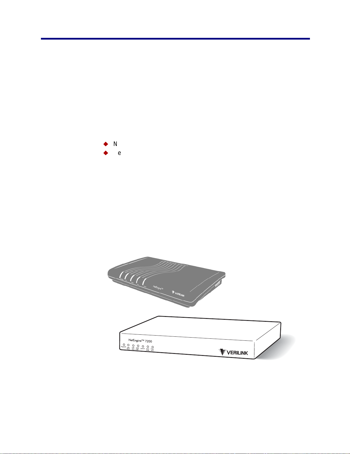
6000 Family IAD
7000 Family IAD
POWER
LAN
LAN
WAN
VOICE
LINK
DCE
ACT
DCE
LINK
LINK
ACT
Figure 1–1. NetEngi n e 6000 and 7000 Integra ted Access Devices
NetEngine IAD User Guide
Page 21
Introduction 2
Data Interfaces
NetEngine 6000 IAD Family
The data connection through the IAD s upports IEEE 802.10-compliant
brid ging and routing.
When the IAD is configured for routing, it supports Routing Information
Protocol (RIP) version 1, version 2, or static IP routing. The IAD complies
with RFC-1812 when interfacing with Version 4 IP routers.
The WAN subsystem supports the following interfaces:
u
ATM data transport via xDSL and T1 /E 1 per RFC 14 83 or RFC 236 4
u
Frame Relay data tran sp ort via xDSL and T1/E1 pe r R F C 1490
u
Frame Relay data tran sp ort per RFC 1483 with Q.922 frames
The Verilink N et Engineä 6000 IAD fam ily provides a highly
inter ope rabl e, co st-ef fec ti ve voi ce and high -spe ed dat a int egr atio n sol utio n
that is compat ible with industry-leading DSLA M and Voice Gateway
manufact urers. Thes e I ADs prioritize voice packet s a nd dynamically
allo c ate bandwi dth betwe en voice and da ta servic es.
Features
u
Interoperable with DSLAMs based on Alcatel, Texas Instruments,
MetaLink, and Globespan chip sets. These include Lucent Stinger/
TNT, Nokia Speedlink System, Promatory IMAS, AccessLan
PacketLoop, Accelerated Networks AN-3200, CopperMountain
CopperEdge, and Paradyne GranDSLAM DSLAMs, for example.
u
Seamless voice and high-speed data integration over xDSL or T1/E1
u
Supports data rates from 144 Kbps to 2.3 Mbps and customer premise
interfaces including POTS, 10/100BaseT Ethernet, BRI
u
Compatible with WAN proto c ols inc luding ATM and Frame R elay
u
BRI IAD supports ISDN BRI telephone interface
u
RJ11 POTS interface with Loop Start or Ground Start
u
Dynamic and static IP rou ti ng and bridgin g c apabilities
u
Firewall support via IP f ilt ering
u
DHCP and NAT to support IP address management
u
Managem ent capabilities including Telnet, SN M P and TFTP
IADs in the 6000 family are characterized by different WAN interfaces, and
different voi ce c apac it y :
u
NetEngine 6100 IADs—provides WAN access over AD SL, and
telephone suppor t for 4 or 8 voice por ts (6100-4 and 6108).
u
NetEngine 6200-8 IAD—provid es W AN access via T1 lines, and
provides 8 voice ports.
u
NetEngi n e 6200c IAD s— provides WAN access via channelized T1/
E1 lines, a nd provides 4 or 8 voice ports (6 204c and 62 08c).
u
NetEngine 6300 IADs—provides voice services and high-speed
Internet or corporate connectivity over SDSL, and provides 4 or 8 voice
ports (6300-4 and 6300-8).
NetEngine IAD User Guide
Page 22
Introduction 3
u
NetEngine 6500 IADs—provides voice services and high-speed
Internet or corporate connectivity over G.SHDSL, and provides 4 or 8
voice por ts (6504 and 6508).
u
NetEngine 6104i/6504i IADs—provides voice services and high-
speed Internet or corporate conn ec t iv it y ov er ADSL (61 04i) or
G.SHDSL ( 65 04i), plus 4 ISDN Basic Rat e Interface (B R I ) ports for up
to 8 voice extensio ns.
Physical and electric al specifications for eac h I AD are listed in Appendix
C, NetEngin e IA D Specific at ions on page 279.
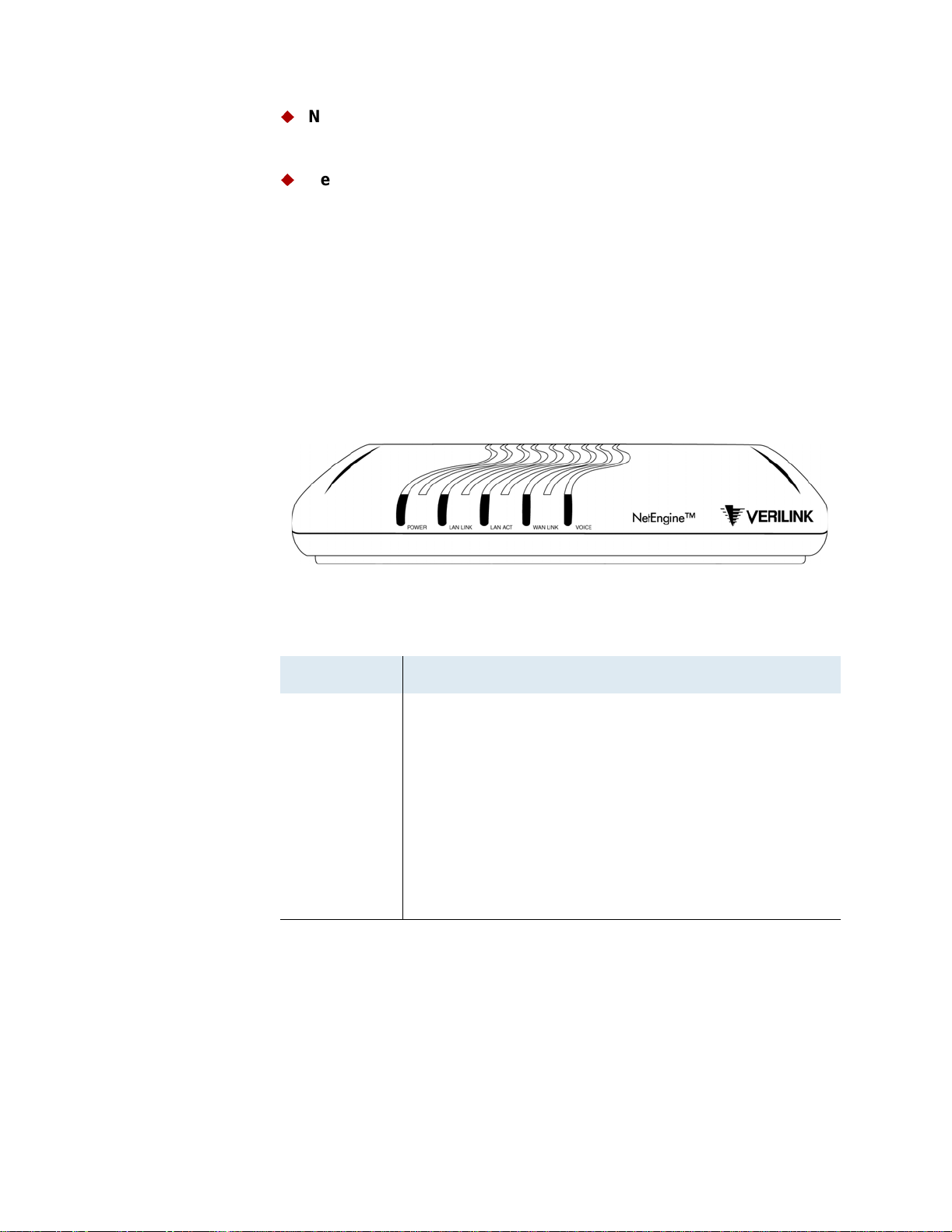
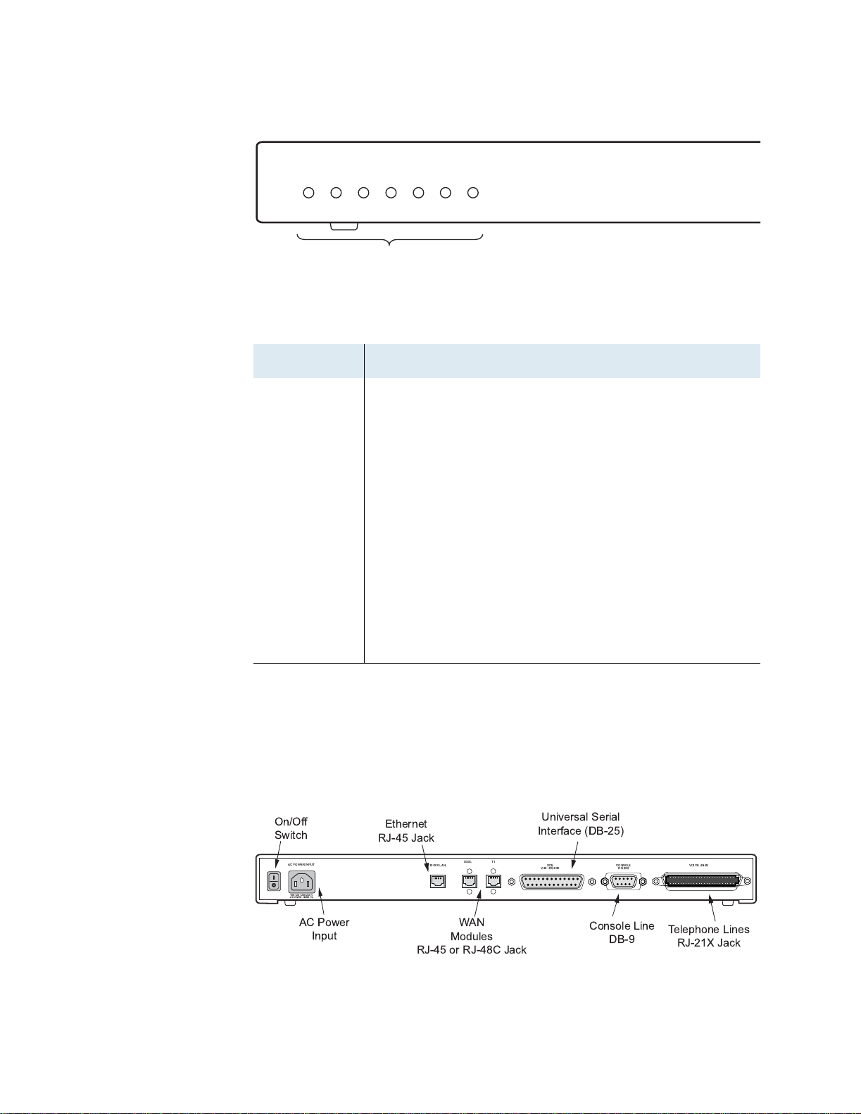
Front Pa nel Power and Status Indicators
The front panel of the IAD c ontains sever al LEDs. Thes e LEDS pro v ide
general information about the operational status of the IAD.
Figure 1–2. 6000 Family Front Panel Indicators
Table 1–1. 6000 Family Front Panel Indicators
LED Description
POWER Illuminates when the IAD is powered on.
LAN LINK Illum inates when the re is an opera t ional LAN conne c t ion
on the Ethernet port.
LAN ACT Flashes when there is activity on the Ethernet port.
WAN LINK Flashe s as the IA D is estab lis hing a link, and illumin at es
solid when there is a proper connection on the WAN port
and synchronization has been achieved.
VOICE Illumin at es w hen there is ac t iv it y on t he voice ports.
When c onnected to a J etst ream Voice Gateway, it
remains lit, and blinks whe n t here is activity.
NetEngine IAD User Guide
Page 23
Introduction 4
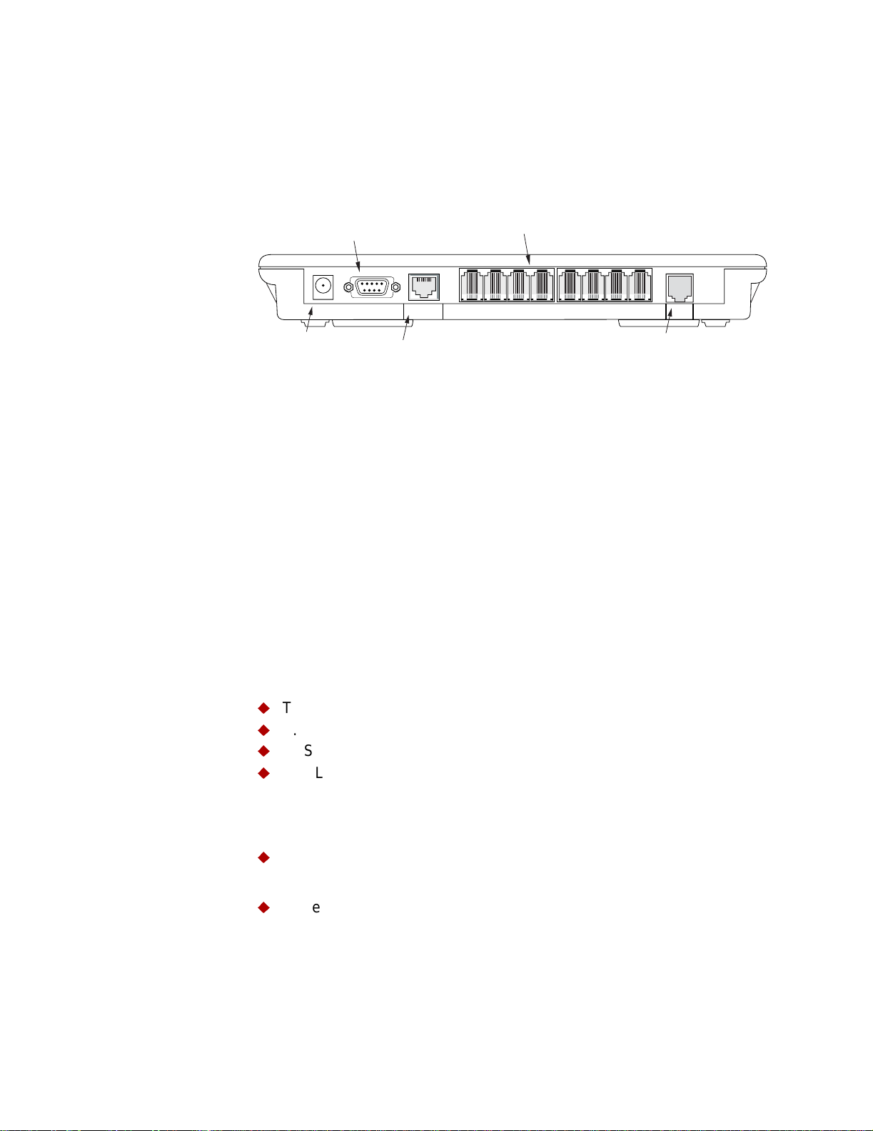
Rear Panel Connectors
On the rear panel (Figure 1–3), the IAD contains several connectors. The
type and p os it ion of the WAN and te lephone connectors vary by IAD.
Figure 1–3. Typical 6000 Family Back Panel Connectors
Console (DB-9)
Serial Connector
POTS Telephone Lines
RJ-11 Jacks
PWR
Power
Receptacle
CONSOLE
Ethernet (RJ-45)
10/100 LAN
LINE
1 LINE 2 LINE 3 LINE 4
LINE 5 LINE 6 LINE 7 LINE 8
WAN Module
RJ-45 or RJ-48C Jack
WAN
DC Power Adapter
Connects the IAD to any AC outlet of 90-250 volts via an external, 18 volt
power su pply.
RS-232 Console Port
Connects the IAD to a PC using a straight through 9-pin serial (DB9 RS-
232) cable, for the purpose of using a t erm inal emul at or f or IAD
configur at ion and man agement.
10/100Base-T Ethernet Port
Connects the IAD to the local area network using a CAT-5 straight through
Ethernet ca ble, or direct ly to a PC f or accessing via Telnet (using a cro ssover cabl e, cu s to m er-supplie d).
WAN Interfaces
Depending on the IAD, WAN int erfaces inclu de the follow ing:
u
T1/E1— us es an RJ48 co nnector for the co nnection.
u
G.SHDSL—uses an RJ11 connector for the connection.
u
SDSL—uses an RJ45 connector for the connection.
u
ADSL—uses an RJ45 connector for the connection.
Telephone Interfaces
6000 fam ily IA D s hav e varying te lephone capac it y. These IADs s upport:
u
4 or 8 analo g te lephones via R J 11 POTS ports
—or—
u
8 telephone extens ions via 4 BRI ISD N S0 ports.
NetEngine IAD User Guide
Page 24

Introduction 5
NetEngine 7000 IAD Family
The Verilink N et Engineä 7000 IAD fam ily provides a highly
interoperable, cost-effective broadband so lution for voic e and high-s peed
data integration that is compatible with industry-leading DSLAM and Voice
Gateway manufacturers. These IADs prioritize voice packets and
dynamically allocat e bandwidth be tween voice and data services.
Features
u
Interoperable with DSLAMs based on Alcatel, Texas Instruments,
MetaLink, and Globespan chip sets. These include Lucent Stinger/
TNT, Nokia Speedlink System, Promatory IMAS, AccessLan
PacketLoop, Accelerated Networks AN-3200, Coppermountain
CopperEdge, and Paradyne GranDSLAM DSLAMs, for example.
u
Seamless voice and high-speed data integration over xDSL or T1/ITE1
u
Supports data rates from 144 Kbps to 2.3 Mbps and customer premise
interfaces including POTS, 10/100BaseT Ethernet
u
Compatible with WAN proto c ols inc luding ATM and Frame R elay
u
RJ21X PO T S interface w ith Loop Start or Ground Start
u
Universal Serial Interface supports V.35 and EIA-530
u
Dynamic and static IP rou ti ng and bridgin g c apabilities
u
Firewall support via IP f ilt ering
u
DHCP and NAT to support IP address management
u
Managem ent capabilities including Telnet, SN M P and TFTP
IADs in the 7000 family are characterized by different WAN interfaces and
different voi ce c apac it y :
u
NetEngine 7216 IAD—provides WAN access over T1/E1, and
telephone suppor t for 16 voice ports via RJ21X co nnector.
u
NetEngi n e 7216c IAD —provides WAN access over channelized T1,
and telephone support for 16 voice ports via RJ2 1X connector.
u
NetEngine 7316 IAD—provides WAN access over SDSL, and
telephone suppor t for 16 voice ports via RJ21X co nnector.
Physical and electric al specifications for eac h I AD are listed in Appendix
C, NetEngin e IA D Specific at ions on page 279.
Front Pa nel Power and Status Indicators
The front panel of the IAD c ontains several LEDs. Th es e LEDs provide
general information about the operational status of the IAD.
NetEngine IAD User Guide
Page 25
Introduction 6
Figure 1–4. 7000 Family IAD Front Panel
Front Panel
NetEngine 7200
POWER LAN
LINK
LAN
ACT
WAN
LINK
VOICE
DCE
LINK
DCE
ACT
Status Indicators
Table 1–2. Front Panel LEDs
LED Description
POWER Illuminates when the IAD is powered on.
LAN LINK Illum inates when the re is an operational LAN conne c t ion
on the Ethernet port.
LAN ACT Flashes when there is activity on the Ethernet port.
WAN LINK Flashe s as the IA D is estab lis hing a link, and illumin at es
solid when there is a proper connection on the DSL WAN
port and synchronization has been achieved.
VOICE Illumin at es w hen there is ac t iv it y on t he voice ports.
When c onnected to a J etst ream Voice Gateway, it
remains lit, and blinks whe n t here is activity.
DCE LIN K Illuminates when there is a link betwe en the IAD and
data comm unications equipment (DCE).
DCE ACT Ill um inates or blinks when the re is activity on th e D C E
link.
Rear Panel Connectors
On the rear panel, the IAD contains several conne c to rs . T he WAN
connectors vary by IA D —both are present, but one has a perm anently
attached m eta l sh ield to prevent use.
Figure 1–5. 7000 Family IAD Back Panel
,!,--
./+
0,* 102
! "
# # !$ %&
0/
1+
*++
!
.'.
23 .
1+- 4'(5
"#6! .6
'()
,.,*
.6
",1*1*.'*
NetEngine IAD User Guide
Page 26

Introduction 7
AC Power
Connects the IAD to an AC outlet of 108-130 volts via an AC power cord.
10/100Base-T Ethernet Port
Connects the IAD to the local area network using a CAT-5 straight through
Ethernet ca ble, or direct ly to a PC f or accessing via Telnet (using a cro ssover cabl e, cu s to m er-supplie d).
WAN Interfaces
Depending on the IAD, WAN int erfaces inclu de the follow ing:
u
T1/E1— us es an RJ48 co nnector for the co nnection.
u
SDSL—uses an RJ45 connector for the connection.
Universal Serial Interface (USI) Port
The USI port is configurable for RS-530 or V.35. When configured as an
RS-530 port, you may use a straight through DB25 serial cable for
connection to your leas ed line DSU/C SU equipment. When co nf igured for
use as V.35, Black Box Co rporation pr ov ides a cable (FA058) fo r
conversion purposes. To convert from RS-530 to RS-449, Black Box
provides a c able EDN57J . By notifying you of th eir availabil ity, Verilink
neither endorses or recommends these pr oducts.
For USI port pinouts when configured as RS-530, V.35 or RS-449, see
Table D–9 on page 291.
RS-232 Console Port
Connec ts the IA D to a PC , us ing a straight t hrough 9-pin se rial (DB9 RS-
232) cable for the purpose of using a t erminal emulator for co nf iguration
and management.
Telephone Interfaces
Each 7000 family IAD suppor ts 16 analog teleph ones via an RJ -11 jack.
NetEngine IAD User Guide
Page 27

Introduction 8
NetEngine IAD User Guide
Page 28
2. Quick Start Guide
This chapter describes the steps to install, connect, and set the IP address
of the N et Engine IAD . I t introd uc es the menu interface and describes how
to per for m ba si c con fi g ura ti on for co mmon L AN an d WAN envi ron men t s. It
also des c ribes basic operations—resetting th e I AD , and logging off.
In many c as es, all the information you nee d t o ge t an I AD up and running
in a custom er’s premises is contained in this sin gle chap t er.
This chapter contains the following topics:
u
Unpacking t he IAD (page 10)
u
Installing th e I AD (page 10)
u
Connecting via Terminal Emulator (page 11)
u
Resetting the IAD (page 10)
u
Powering up the IAD (page 12)
u
Logging on to the IAD (page 12)
u
Setting the Ethernet port IP address (page 13)
u
Connecting via Telnet (page 16)
u
Basic IAD c onfiguration (page 20)
u
Connecting the LAN, WAN, USI and Telephones (page 20)
u
Confirming proper s et up (page 22)
In most insta llat ions, you’ ll proceed thro ugh these to pic s in order. If your
situation varies, complete information on installation, connection,
configur at ion and trou bleshooting is c ontained in the ref erence chapters
following this chapter.
NOTE
When the IAD prompts y ou f or input, the current va lue is
displayed in parentheses . To conveniently a c c ept the current
value, just press Enter.
NetEngine IAD User Guide
Page 29
Quick Start Guide 10
Unpacking the IAD
Each IAD is packed and shipped in a durable container. If you haven’t
already done so, open the container and unpack t he IAD. Caref ully
remove the IAD from t he pac k age and packing materia l.
IAD Package Components
Each IAD is s hipped with t he c omponents lis t ed below. As you unpack
them, note their condition and identity, and compare the list to the packing
list in the package.
u
AC power adapter and cord (6 feet long), or AC power cord
u
Agency Complian ce inf ormation sheet
u
Ethernet ca ble (straight th rough), 7 fee t lo ng
u
WAN cable (var ies by int erface), 7 fee t long
If you note any v is ible damag e, or c om ponents are missing, notify the
shipping company immediately to make a damage claim. Contact the
company fr om w hich the IAD w as purchased (Verilink, or an authorized
distributor) to obtain a Return Material Authorization (RMA) for return of
damaged equipment, or to order missing components.
NOTE
We suggest you keep the s hipping conta iner and packing
material for future shipping or storage of the unit.
Installing the IAD
LAN LINK LAN ACT WAN LINK VOICEPOWER
LAN LINK LAN ACT WAN LINK VOICEPOWER
After you unpack the IAD, find a suitable location to install the IAD in the
customer’s premises. Ideal locations include computer equipment room, or
a telephone or wiring closet. You can locate the IAD in an equipment rack,
on a table or sh elf , or it m ay be wall-mounted. Install th e I AD in a location
that is generally protec t ed and the IAD will be undi sturbed.
AC Power and Uninterruptible Power Supply
The IAD requires access to AC power (NEMA 15-3R). Make sure the IAD
is located within six feet of an AC power outlet. Locate the nearest power
outlet and plug in the supplied AC power adapter or AC power cord. If
there is an uninterruptib le power supply on premises, plug th e AC power
adapter or c ord into that power sourc e.
Ensure that the power cord conveniently and safely reaches the rear panel
of the IAD where the po w er plug or adap te r jac k is loc ated.
6000 Family
Do not attach t he AC power adapter, or power up th e unit at
this time.
7000 Family
Plug in the power cord, but do not power up the unit
Clearance Requirements
If you install the IAD horizontally, make sure you maintain at least 2 inches
of horizon tal d is tan c e f rom other IADs or other electronic equi pm ent, to
ensure adequate ven t ilat ion and heat dis s ipation. If you ins ta ll th e I AD
NetEngine IAD User Guide
Page 30

Quick Start Guide 11
vertically, ensure at least 3 inches of distance between other IADs or other
equipment.
Connect via Terminal Emulator
NOTE
6000 fami ly IA D s ma y be stacked on to p of one anothe r,
when mounted horizontally. 7000 family IADs may be rack
mounted.
Wiring Requir ements
Make sure that the t elephone wiring, LA N and WAN cables reach the I AD
and can be dressed in a manner that is safe for the wiring, does not pull or
creat e lateral stress on the connectors or ports on the rea r of the IAD , and
does not p res ent a trip haz ard to person nel working in t he vicinity of th e
equipment. Do not connect any cables or wiring at this time.
The IAD is configured and managed from eithe r t he c onsole or E th ernet
port. Mos t ne t w ork engineers us e Telnet to access the IAD v ia Et hernet.
After you use a terminal emulator program via the console port to set the
IP addres s , you may con tin ue to use a terminal emulat or via the con s ole
port if you ch oose.
NOTE
Before you can connect to the IAD via Telnet, make sure the IP address is
set correctly for this network. To do so, follow the steps, each described in
detail below:
After a period of inactivity (three minutes by default), the IAD
automatic ally termin at es c onsole-bas ed and Telnet sessions
to maintain security. T o change this value, see Configuring
the Console Timeout Perio d on page 38.
1. Connec t the IAD to a PC
2. Log in to the IAD
3. Se t the IP addres s
NOTE
Be sure that the IAD and PC are both powered OFF before
connecting the console cable. If both devices are not turned
off when you connect the cables, you may place the IAD in an
unstable state, and you may need to reset one or both
devices before you can perform configuration tasks.
Connect the IAD to a PC
To connect the IAD to a PC via the console port:
1. Turn off both dev ices and ins ert the male co nnector of a D B9 serial
cable into the console port on the IAD.
2. Insert the female connector of the cable into a serial (COM) port on
your PC.
NOTE
See RS-232 DB-9 Console Port Pin Assignments on page
289 for console port specifications.
NetEngine IAD User Guide
Page 31

Quick Start Guide 12
Power Up the IAD
1. With the console cable connected, on 6000 family IADs plug the AC
power adapter into the IAD. On 7000 family IADs, turn on the power
switch, loc at ed on the ba c k pan el. T his s ta rts th e I AD and it execu te s
the boot pr oc es s t o begin norm al operatio n.
2. Verify that the Power indicator on the front panel illumina t es .
NOTE
As the IAD b oot s, it se nds status mes s ages to the console
port. If you are connect ed, you will see th e boot sequence
progress.
Log in via a Terminal Emulation Program
With a serial cable connected, follow these steps to log in to the IAD:
1. Open a terminal emulation program (Hyperterminal, for example).
2. Se lec t th e C OM port to which the IAD is connected.
3. Type or selec t th e f ollowing set ti ngs and save y our changes.
Tabl e 2–1. Terminal Emulato r Settings
Setting Value Setting Value
Bits per sec ond 19,200
Data bits 8
Parity None
4. Press Enter. The IAD displays the log in message:
Enter Lo gin ID >
NOTE
If the IAD does not respond, make sur e th e IAD is powered
up, check the cable and connections, and review the settings.
Stop bits 1
Flow control None
Emulati on ANSI or VT 100
5. Type the def ault supervis or level user ID (Supervisor) (or your user
ID if changed) and press Enter. Note that both the user ID and
password are case-sensitive.
Table 2–2 below lis ts the def ault user IDs and passwo rds .
Tabl e 2–2. Defau l t IAD U ser IDs and Passwords
Security Level User ID Password
User <enter> <Enter>
Network
NetMan <Enter>
Administrator
Supervisor Supervisor supervisor
For i nf or mat io n on s ecu rit y lev el s, an d use r I D and p as swor d man age ment
see IAD Security on page 24.
6. The IAD displ ay s th e pas s w ord messa ge:
Enter Pa ssw or d >
NetEngine IAD User Guide
Page 32

Quick Start Guide 13
7. Type the default password (supervisor, or your password if
different ) and press Enter.
8. If lo g in is not succes s fu l, th e IA D dis plays the fol low ing messa ge:
Invalid UserID or Password - Try again
Press any key to continue...
9. Pr es s any k ey, and repeat t he log in sequ ence. If you can not log in,
call your support provider for assistance.
When you first log in, the IAD displays the Main menu. The menu may
vary, depending on the IAD.
Figure 2–1. Main Menu
*****************************************
Main Menu
*****************************************
1. Repo rt s Menu
2. Conf ig ur e IP Ro ut er
3. Conf ig ur e Bri dg e
5. Conf ig ur e WAN
6. Conf ig ur e LAN
7. Conf ig ur e SNM P
8. Conf ig ur e Log in
9. Syst em Uti lit ie s
D. Conf ig ur e DHC P Se rv er
M. Conf ig ur e Mul ti ca st
N. Conf ig ur e NAT
T. Tele ph on y Clo ck Rec ov er y
Z. Diag no st ic s Menu
C. Comm an d Li ne In te rf ac e
R. Rese t Sy st em
P. Voic e Pa th Conf ig ur e
E | A | O. CopperCom Call Control
Options E, A and O
vary, depending on the
voice gateway sele cted
in the Voice Path
Configur e c om m and.
Setting the Ethernet Port IP Address
Before yo u c onfigure the Ethernet IP address, yo u s hould kn ow the IP
address and subnet m as k th at is to be assigned to t his port. It may be
displaye d on the work order, or you may obtain or det ermine the
appropr iat e I P address by c ons ulting with th e network ad m inistrator.
The IAD is shipped with a null IP address and subnet mask. To configure a
port I P address:
1. On the Main menu, type 2 to select Configure IP Router.
2. The IAD displ ay s th e R outer Configuration menu.
NetEngine IAD User Guide
Page 33

Quick Start Guide 14
Figure 2–2. Router Configuration Menu
*****************************************
Router Configuration Menu
*****************************************
C. Configure Port IP Address
U. Unconfigure Port IP Address
M. Configure Port Max Transmission Unit
S. Add/Remove a Static Route
R. Enable/Disable RIP
V. Config ur e RI P Ve rsi on by Po rt
P. Config ur e RI P Po iso ne d Re ve rs e by Po rt
N. Config ur e DN S Cl ien t
H. Configure DHCP Client
L. Configure DHCP Relay
T. Configure Telnet Server Port
F. Configure IP Filtering
Q. Configure IP Header Compression
B. Config ur e LA N IP Broa dc as t De st ina ti on
D. Displa y Ro ut e Ta bl e
Type C to select Configure Port IP Address.
3. The IAD displays the following menu (sample—all options shown). The
interfaces t hat display depend on the s pec ific IAD:
Figure 2–3. Router Configuration Menu
Availa bl e In te rf ac es :
1. G2237 xDSL
1. G7070 ADSL ATU-R
1. T1/E1
1. SDSL
2. 10/100BaseT Ethernet
0. (Abort)
Type 2 t o s et th e I P address for th e Ethernet port.
4. If the IP address is configured for the port, the IAD displays information
about the int erf ace and a pr om pt:
IP inter fa ce s on port 2 :
ID IPAddr IPMask Priority
0 92.1.1.90 255.255.255.0 NORMAL
Enter connection to configure:
Type the ID numbe r of th e c onnection t hat you want t o c onfigure (in
this case, 0) and pr ess Enter.
5. Type the new IP address, and press Enter (or press Enter to retain the
current IP address).
NetEngine IAD User Guide
Page 34

Quick Start Guide 15
6. The IAD displ ay s th e f ollowing infor m at ion:
Current subnet mask = 0.0.0.0
Enter new subnet mask for this interface:
Type the new subnet mask (usually 255.255.255.0) and press Enter.
7. The IAD display s th e f ollowing inst ructions:
Select priority Normal/High [N/H] (N):
Give the in te rf ac e normal pr iority—type N or press Ente r.
8. Type Y or Ent er to save the new IP addre s s and subnet m as k .
9. To exit, press Escape, then type Y to terminate the session.
10. Quit the terminal emulator program.
11. Reset the IAD (following) for the new IP address to be in effect.
Resetting the IAD
NOTE
If you plan to us e Telnet for configu rat ion tasks, this is a good time to
disconn ec t th e s erial cable from t he PC and IAD .
Many conf iguration task s re quire that yo u reset (or res tart) t he IAD before
the new set t ings or config uration will take effec t . When you use the menu
interface (or the Comm and Line Interf ace on page 243) to make change s ,
or change t he physica l ch aracteristics of th e I AD (s uch as cha nging the
Ethernet port MAC ad dress), you mus t res et the IAD.
The IAD stores all conf iguration sett ings in mem ory. When it res tar ts, it
loads the last configuration saved before it was powered down or
restarted. When restarting is required, it will be included as a step in the
configur at ion process .
You can reset the IAD in two ways.
To reset the IAD from the menu:
1. On the Main menu, type R to select Reset System.
The IAD displays the following instructions:
Press R to Re se t no w- >
2. Type R again. This resets and starts the IAD with your new settings.
3. To log in again, enter yo ur user ID and pas s w ord.
When you co nf igure the IAD , yo u m ust restart the IAD each
time you change the settin gs for those ch anges to take eff ect.
You may make several configuration changes before
resetting if you choose, for efficiency.
To reset the IAD manually:
On a 6000 family IAD, unplug the pow er adapter from the IAD an d t hen
plug it back into the IAD. On a 7000 family IAD, turn the IAD off, then back
on. Be sure to complete your task and return to the Main menu before
restarting the IAD in this manner.
CAUTION
Resetting th e I AD t erminates all t ele phone calls and
computer s es s ions in progre ss. You should ensure that there
no services are being rendered before resettin g t he IAD.
NetEngine IAD User Guide
Page 35

Quick Start Guide 16
Connecting via Telnet
To manage the IAD via the LAN (or Intranet), you must set an IP address
for the Ethernet port be fo re you can us e Telnet to access th e IAD.
NOTES
Although you can also access the IAD using Telnet via the
WAN (provided a m anagem ent DLCI or PVC is configu red
alon g w ith a WAN IP ad dress), th is sectio n describes
connecting via the LAN. For information about setting the IP
address of t he WAN port, see Chapter 6, WAN Configuration
on page 51.
If you configure a RADIUS server, you must use a RADIUSauthenticated User ID/password for Telnet access. If the
RADIU S se rv er or th e co nnec t ion to t he R ADI US s erv er g oe s
down, Telnet ac ce s s will not work . For informat ion about
configuri ng a RADIUS s erver, see RADIUS Server Settings
on page 27.
Running Telnet
Before you use Telnet to log in to the IAD, make sure that the IAD and
your PC ar e c onnected to th e s am e network vi a s tr aight-through Ethernet
cables (or directl y conn ect ed via a cross- ov er cabl e), a nd yo u know the IP
address of the IAD. Both devices must be on the same subnet.
Follow these steps to log in:
1. Run Telnet on yo ur PC.
2. Type the IP a ddress of the Et hernet port (page 13), click Connect and
then press Enter to gain the attention of the IAD.
3. The IAD responds by displaying the log in message:
Enter Lo gin ID >
4. Type your us er ID and pres s Enter.
NOTE
After a period of inactivity (three minutes by default), the IAD
automatic ally termin at es c onsole-bas ed and Telnet sessions
to maintain security. T o change this value, see Configuring
the Console Timeout Perio d on page 38.
Default us er IDs and pass w ords are listed in Table 2–2 on page 12. For
information on security levels, and user ID an d pas s w ord manag em ent
see IAD Security on page 24.
5. The IAD displays the password message:
Enter Pa ssw or d >
NetEngine IAD User Guide
Page 36

Quick Start Guide 17
4.Type your password and pres s Enter to display the Main menu.
*****************************************
Main Menu
*****************************************
1. Reports Menu
2. Configure IP Router
3. Configure Bridge
5. Configure WAN
6. Configure LAN
7. Configure SNMP
8. Configure Login
9. System Utilities
D. Configure DHCP Server
N. Configure NAT
T. Teleph on y Cl oc k Rec ov er y
Z. Diagnostics Menu
C. Command Line Interface
R. Reset System
P. Voice Path Configure
Using the Menu Interface
NOTE
The NetEngine IAD provides an AN SI -terminal-base d men u interface for
system configuration and monitoring. When you log in, the IAD displays
the Main menu.
The c omman d s di sp lay ed in s om e me nus (i ncl u din g t he Mai n m enu) d if f er,
depending on the level at which you log in. Figure 2– 4 on page 18 displays
the Main menu when yo u log in at the Sup erv isor secu rit y lev el. Figure 2–
5 on page 18 displays the Main menu when you log in as Network
Administrator, and Figure 2–6 on page 18 displays the Main menu when
you log in as User.
The user ID and password transmit as clear text, which may
be captured by unauthorized individuals. If you are concerned
with network security, you may not want to use Telnet to
configure th e I AD .
NetEngine IAD User Guide
Page 37

Quick Start Guide 18
Figure 2–4. Main Menu for Supervisor
*****************************************
Main Menu
*****************************************
1. Repor ts Men u
2. Confi gu re IP Ro ute r
3. Confi gu re Bri dg e
5. Confi gu re WAN
6. Confi gu re LAN
7. Confi gu re SNM P
8. Confi gu re Log in
9. Syste m Ut il it ie s
D. Confi gu re DHC P Ser ve r
M. Confi gu re Mul ti cas t
N. Confi gu re NAT
T. Telephony Clock Recovery
Z. Diagn os ti cs Men u
C. Comma nd Lin e In ter fa ce
R. Reset System
P. Voice Pat h Co nf igu re
Options E, A and O vary,
depending on the Voice
Gateway selected in the
Voice Path Conf igure
command. Thes e options
only dis play when lo gged
on as Supervisor.
E. Toggl e CM CP Deb ugg in g
O. Manag e MG CP Emb edd ed Cli en t Se lec ti on
Figure 2–5. Main Menu for Network Administrator
*****************************************
* Main Men u *
*****************************************
1. Repor ts Men u
2. Confi gu re IP Ro ute r
3. Confi gu re Bri dg e
7. Confi gu re SNM P
8. Confi gu re Log in
9. Syste m Ut il it ie s
D. Confi gu re DHC P Ser ve r
M. Confi gu re Mul ti cas t
N. Confi gu re NAT
Z. Diagn os ti cs Men u
R. Reset System
Figure 2–6. Main Menu for User
*****************************************
Main Menu
*****************************************
1. Repor ts Men u
8. Confi gu re Log in
NetEngine IAD User Guide
Page 38

Quick Start Guide 19
Navigating the IAD Menu Interface
Menus in the IAD configuration system are arranged hierarchicall y . That is,
you select single-key options to navigate down to display sp ec ialized
menus and specific tasks, and press the Escape key successively to
return bac k to menus higher in the interfac e.
The specific menus, submenus and commands that display depend on the
interfaces for the specific IAD, the options configured and the security level
that you use to log in.
To select a m enu item, just t y pe the opt ion dis pl ayed to t he left of the it em.
Although c haracter options are di sp lay ed in upper c as e, the IAD accepts
both upper and lower case options. It is not necessary to press Enter after
typi ng the select ion to exec ute it—the I AD im m ediately responds w ith a
request for input or another menu for more options.
For a hierarc hical map of th e M ain menu, its menus and commands , se e
Appendix A, Me nu Map on page 275.
Entering Settings and Values
When th e I AD requests input for a s etting or configur ation valu e, type it at
the promp t . P res s t he Enter key to terminate th e input and proc eed to the
next step.
The IA D resp on ds with err or m ess ag es i f a val ue is in co rre ct , or it dis pl a ys
the curren t me nu so you can c ont inue with related tasks.
Using Default or Current Values
The IAD dis plays a defa ult or current value in parent heses immediately to
the right of each message, just to the left of the comm and prom pt . To
accept this value, just press the Enter key.
For example, when the following message displays:
Enter a new sub ne t ma sk for th is int er fac e:
(255.255.255.0) -)
You may press Enter to c aus e the IAD to s et 255.255.255.0 as the
subnet mask value . U s ing the Enter key t o s k ip t hrough def ault or current
values often speeds the process of proceeding through a family of input
steps, to quic k ly get t o t he input step wh ere you want to ch ange a value.
NetEngine IAD User Guide
Page 39

Quick Start Guide 20
Exiting the Menu Interface
To exit the menu interface , retu rn to the Main menu using the Escape key,
and press Escape one more time. The IAD asks you to confirm—press Y
to exit (or pres s R et urn to acce pt th e default val ue (N) to cancel the exit).
After exiting , yo u c an quit the ter m inal emulato r or Telnet application. If
you made ch anges to the co nf iguration th at require rese tting the IAD, be
sure to do so before exiting.
Basic IAD
Configuration
Connecting LAN, WAN, USI and Telephones
Each IAD has a default c onfiguration w hen it is shippe d f rom the fact ory.
At a minimum, you should view th e c onfiguration and check the following
settings for probable update for each customer installation:
1. Configure the LAN IP addr es s , if no t already com pleted (page 13)
2. Configure ea c h of t he WAN options and th e DSLAM prof ile (WAN
Configuration on page 51)
3. Create and configure at least one DLCI (page 93) or PVC (page 81) for
data traffic and s et th e WAN I P address (WAN Configuration on page
51.)
4. Configure static or default route or enable bridging for all data traffic
5. Create and configure a DCLI (page 93) or PVC (page 81) for voice
where required and select appropriate voice gateway se ttings.
6. Reset the IAD (page 15) to enable all configuration changes.
In this sect ion, you’ll connect the IAD to th e c om puter and te lephone
systems the IAD is intended to support.
Before proceeding, make sure that you have an appropriate serial cable
for your PC, identify the LAN switching equipment where you’ll connect the
IAD, identify the telephone cables, and verify that WAN service is installed,
and configured by t he service provider.
When you’ve completed this section, reset the IAD so it can synchronize
these physical connections.
Ethernet LAN Connection
The Ethernet LAN port on the rear of the IAD is an RJ45 jack for 10/
100Base-T Ethernet cables. If the IAD is intended to act as an Internet
gateway for the LAN in the customer’s premises, connect the IAD to the
switch, hub or router us ing an Ethern et s tr aight-through cable.
NOTE
To temporarily connect the IAD directly to a PC for Telnet
configuration (without going through a hub or router), be sure
to use an Ethernet cros s -ov er cable (cust omer-supplied).
W AN Con nections
WAN connections vary, based on the WAN int erf ace on your IAD . I dentify
the WAN interfac e on your IAD , and proceed to th e appropriat e s ection.
NetEngine IAD User Guide
Page 40

Quick Start Guide 21
Making G.SHDSL Connections
G.SHDSL -equipped IAD s us e an RJ11 connector on th e rear panel for
WAN connection. To make the co nnection, plug the WAN cable into the
RJ11 WAN connector. Table D–7 on page 290 lists the G.SHDSL
connector pinouts.
Making SDSL or ADSL Connections
SDSL- and ADSL-equipped IADs use an RJ45 connector on the rear panel
for WAN connection. T o make the connection, plug the xDSL cable into the
RJ45 WAN connector. Table D–6 on page 290 lists the RJ45 WAN pinouts.
Making T1/E1 C onnections
T1/E1-e quipped IADs use an RJ4 8 c onnector on the IAD rear panel for
WAN connection. To make the connection, plug the c able from th e ATM
network into the RJ48 WAN connector. Table D– 8 on page 291 list s the
pinouts for the T1/E1 connector.
USI Connection (7200, 7300)
7300
LAN LINK LAN ACT WAN LINK VOICEPOWER
7200
7300
7000 fami l y IA Ds hav e a U niv er sal Se ri al I nt er fac e ( USI ) p or t,
configura ble for V.35 or EI A-530 (page 37).
If your IAD is equipped w it h a U SI port, you may c onnect it no w. Located
on the rear panel, the port us es a s hielded, DB 25 connect or. The
connector is DCE— data is transmitted on the receive pin and rec eived on
the transm it pin.
The V.35 or EIA-530 interfaces use different voltage levels. You must
supply the appropriate cable for each interface. Table D–9 on page 291
lists the USI port pinouts and signal specifications.
Telephone Connections
6000 family IADs provide 4 or 8 RJ11 ports for POTS devices, or ISDN
connectors for t elephone service. 7000 family I AD s provide an RJ21X
Amphenol-style connector for connecting up to 16 telephone devices.
These de v ic es m ay be POTS telephones , mo dems, FAX machines , or
other POT S-compatib le devices.
Making RJ11 Connections (6000 family)
The RJ11 POTS port pinouts are telco standard (RJ11 POTS Port Pin
Assignments on page 289). Connect each telephone device to the RJ11
jacks using 26AWG telephone cord or better (user provided).
Making ISDN Connections (6104i, 6504i)
The RJ45 BRI IDSN S 0 ports are telco stan dard (RJ45 BRI ISDN S0 Port
Pin Assignments on page 289). Connect eac h ISDN cable from the IS D N
terminal equipment to the S0 ports on the back of the IAD using 4-wire
cable. The ports provid e PS1 and PS2 pow ering for ISD N t elephones , at
10 power c onsumption units per port .
NetEngine IAD User Guide
Page 41

Quick Start Guide 22
Making RJ21X Connections (7000 family)
The pin assignments for the RJ21X connector are telco standard. Connect
telephone devices fro m an RJ11 jack field, or a punc h down block. Each
line provides a two-wire loop or gro undstart connection. To perform the
connection, use a cust omer-prov ided cable term inated at one end with an
RJ21X connector. After connec t ing each colo r-c oded wire pai r to th e
corresponding telephone connection on the jack field or punchdown block,
connect t he R J 21X conn ec t or t o t he connector on the IAD re ar panel.
Confirming Proper Setup
When you have completed t he tasks in this chapter, reset t he IA D and te st
your configuration.
Reset the IAD
Reset the IAD (page 15) to synchronize the physical connections.
Verify Normal Power Up and Operation
Finally, to test your conf iguration for proper data and voice operation,
perform the operational test (Operational Test on page 272).
NetEngine IAD User Guide
Page 42

3. Administration
This chapter describes how to control security to your IAD, validate users
using a RA D IUS server, configur e SN MP via IP o r EOC, upgrade IAD
software, and perform o th er general and utility-o riented tasks.
This chapt er includes t hese topics:
u
IAD security—setting user IDs and passwords (page 24)
u
Using a RADIUS server for authentication (page 27)
u
Configuring SNMP (page 29)
u
Upgrading IAD system software (page 33)
u
Upgrading ACOS (pa ge 46)
u
Configuring the IAD for LAN connection (page 35)
u
Using syst em utilities (pag e 24)
u
Setting de riv ed timing options (page 48)
u
Resetting the IAD (page 15)
NOTE
When the IAD prompts y ou f or input, the current va lue is
displayed in parentheses . To conveniently a c c ept the current
value, just press Enter.
Polycom, Inc. NetEngine IAD User Guide
Page 43

Administration 24
IAD Security
To maintain IAD security, the IAD provides multi-level login access using a
single use r I D and password , which you can s et at th e f ollowing levels:
u
User
u
Network Administrator
u
Supervisor
The user ID at th e U s er security lev el may be m odified, but the user ID at
the Netwo rk Administra t or and Supervis or level may not be modified.
The passwo rd for each se c urity level may be change d. Alt hough you m ay
use the same password for all security levels, Verilink recommends that
you use a different one for each level. Table 3–2 lists the privileges
available at each security level.
Tabl e 3–1. Secur i ty L evel Privil eg es
Security level Privileges
Supervis or This user level is the highest level. Us ers who
log in as Supervisor have full access to all IAD
feature s (m enu and command line int erface,
including changing User security level user ID
and any level passwords, plus complete IAD
config uration capability.
Network Administr at or Th is user may per fo rm ta sks t hat alter the
networ k se tt in gs of t he IA D, pl u s ha s a cces s to
all of th e d at a ne tw ork in g c onf igu r ati on m enu s,
and can update routi ng and bridg ing
inform at ion and status.
This user can change this level password, and
the User level user ID and password, and has
access to all display-only menus.
This user may not modify WAN or LAN
settings , alt er derived tim ing, use com m and
line interface, or modify voicepath settings.
User Th is user has access to display-only me nus,
and may view the current configuration,
interfa ce and media sta tist ic s , routing and
bridg ing information a nd stat us . This us er may
change this level user ID and password. This
user may not make or save any change s to the
config uration of the IA D .
To maintain IAD security, a user with Supervisor privileges should modify
the User se c urity level user ID and passwords for bot h U s er level and
Network Adm inistrator lev el prior to pla c ing the IAD into production.
NetEngine IAD User Guide
Page 44

Administration 25
Table 3–2 lists the default values for the user IDs and passwords:
Tabl e 3–2. Defau l t U ser IDs and P asswords
Security Level User ID Password
User <Enter> <Enter>
Network
NetMan <Enter>
Administrator
Supervisor Supervisor supervisor
The user ID and password may contain up to 17 alphanumeric characters.
These values are cas e s ensitive; spac es and punctuation chara cters are
not allowe d.
NOTE
The IAD ca n only store on e us er ID and password at each
secu r ity level.
Changing a Password
To change a pas s w ord at any sec urit y level, you mus t s ign on at or abo v e
the security level you’re changing and follow these steps:
1. On the Main menu, type 8 (Configure Login) to display th e Passwor d
Configuration menu.
Figure 3–1. Password Configuration Menu
*******************************************
Password Configuration Menu
*******************************************
1. Chang e Us er ID
2. Chang e Us er Pas swo rd
3. Chang e Ne tM an Pass wo rd
4. Chang e Su pe rv is or Pa ss wo rd
5. Chang e Pr im ar y RAD IU S Se rv er Addr es s
6. Chang e Pr im ar y RAD IU S En cr yp ti on Se cr et
7. Chang e Se co nd ar y RAD IU S Se rv er Addr es s
8. Chang e Se co nd ar y RAD IU S En cr yp tio n Se cr et
9. Displ ay RAD IU S Con fi gu ra ti on
2. Type 2, 3, or 4 to change the password for the selected level.
3. Enter the password for the current level.
4. Enter the new password after the prompt, or press Enter to enter a null
password.
5. En te r t he new password (or Enter) again, to co nf irm t he change.
The IAD immediately updates the password. The next time you log in at
that level, the new password will be in effect.
NOTE
You cannot use the Esc ape key to exit th e pas s w ord updat e
command. To exit, delibe rately ente r an incorrect pas sword
at the confirmation step, or reset the IAD.
NetEngine IAD User Guide
Page 45

Administration 26
Changing the User Level User ID
To change the user ID for the User security level (the only security level
that allows the user ID to be changed), follow these steps:
1. On the Main menu, type 8 (Configure Login) to display th e Passwor d
Configuration menu.
2. Type 1 to change the user ID for the User security level.
Enter new User ID (up to 17 characters) >
3. Type the new U s er I D and press Ent er. The IAD informs you that the
user ID has been updat ed.
4. Reset the IAD (page 15).
Including User ID and Passwords in Config Files
If you create master configuration files for distribution to multiple IADs, you
may include the userid and passwords directly in the configuration file to
reduce configuration tasks .
NOTE
When the user ID and passwords are stored in a
configuration file, the IAD saves the configuration file
immediately upon re booting, with out requirin g t he log on
process. Th e us erid and passw ords are stripped from t he
configura t ion file before sav ing to prevent a secur ity ris k .
Usin g a text edit or, update the confi g f ile by ad ding the fo llowing attributes
in the [user] category:
userid={string}
password={string}
netman-password={string}
support-password={string}
The passwo rd parameter is f or us er level acc es s ; net m an-passw ord is for
network administra t or level access; and suppo rt -pas s w ord is for
supervisor level access.
NetEngine IAD User Guide
Page 46

Administration 27
RADIUS Server Settings
You can us e a RADIUS s erv er to determ ine the validit y of unk nown user
ID/password pairs in your IAD. To use a RADIUS server, set the following
options:
u
Change t he primary or s ec ondary RADI U S Server A ddress
u
Change the primary or secondary RADIUS Encryption Secret
u
Display RADIUS Configuration
NOTE
V erilin k does not provide a RADIUS server. You must provide
a RADIU S se rv er to u se t hi s f eat ure . F or mo re i nfo r mati on o n
RADIUS servers, see RFC 2865.
If you configure a RADIUS server, the IAD must be able to successfully
connect t o th e R ADIUS Se rv er. This req uires WAN configuration, IP
configur at ion, static or de fa ult routes and other configurations fo r y our
network. Additional ly, you must use a R AD I U S-authe nt ic at ed user ID/
password fo r Telnet access. If the R ADIUS serv er become s inoperativ e,
Telnet access w ill not work.
Changing the RADIUS Server Address
To change the primary or secondary RADIUS server address:
1. On the Main menu, type 8 (Configure Login) to display th e Passwor d
Configu rat ion menu (pag e 25).
2. Type 5 to select Change Primary RADIUS Server Address or Type 7
to select Change Secondary RADIUS Server Address.
The IAD displays the following message:
Primary/Secondary RADIUS Server is currently:
Enter new Primary/Secondary RADIUS Server as either
an IP address or name >
3. Type the IP a ddress in one of the followi ng f ormats and pr es s Enter:
u
IP address
u
Fully-qua lif ied host and do m ain names
(for example: radius. Verilink .com—maxim um 42 byte s )
NOTE
If you enter hos t and domain nam es, you mus t c onfigure the
IAD as a DNS c lient (page 114).
4. Reset the IAD (page 15).
Changing the RADIUS Encryption Secret
To change the primary or secondary RADIUS encryption key:
1. On the Main menu, type 8 (Configure Login) to display th e Passwor d
Configu rat ion menu (pag e 25).
2. Type 6 to select Change Primary RADIUS Encryption Secret or type 8
to change Secondary R ADIUS Enc ryption Sec ret .
The IAD displays the following message:
Primary/Secondary RADIUS Encryption Secret is
currently:
Enter new Primary/Secondary RADIUS Encryption Secret
NetEngine IAD User Guide
Page 47

Administration 28
3. Type the new encryptio n k ey and press Enter.
4. Reset the IAD (page 15).
Displaying the RADIUS Configuration
To display the current RADIUS server configuration:
1. On the Main menu, select Configure Login to display the Password
Configu rat ion menu (pag e 25).
2. Type 9 to select Display RADIUS Configuration.
The IAD displays the following information:
Primar y RAD IU S Se rv er :
Primar y RAD IU S Se cr et :
Secondary RADIUS Server:
Secondary RADIUS Secret:
NetEngine IAD User Guide
Page 48
Administration 29
Setting Up SNMP
You can enable SNMP over IP and/ or EOC (whe n t he voice gat ew ay is
AAL2/LES CAS or ELCP). By default, the IAD is configured with SNMP
disabled. When SNMP is enabled and the settings are configured, you can
use SNMP to remotely manage the IAD by get ti ng and sett i ng IAD val ues,
and monitoring IAD events.
The IAD supports the following SNMP settings:
u
System Contact
u
System Name
u
System Location
u
SNMP Com munity
u
SNMP Trap Host IP Address
u
af-vmoa-0172 (AAL2/LES)
The following SNMP traps are supported:
u
System reset
u
Attempts to access SNMP with an invalid community name
u
Starting and stopping TFTP within SNMP
The IAD supports MIBs for RFCs 1213, 1317, 1406, 1493, 1463 as well as
af-vmoa-0172 (AAL2/LES M I B).
Using the SNMP Configuration Menu
To display the SNMP Configuration m enu, type 7 on th e Main menu. T he
following SNMP tasks are accessed from this menu:
Figure 3–2. SNMP Configuration Menu
*****************************************
SNMP Configuration Menu
*****************************************
E. Enable/Disable SNMP via IP
F. Enable/Disable SNMP via EOC
A. Enable SNMP via both IP and EOC
B. Disable SNMP via both IP and EOC
P. Configure System Contact
N. Configure System Name
L. Configure System Location
C. Configure SNMP Community
T. Configure SNMP Trap Host IP Address
U. Enable/Disable SNMP Traps via EOC
D. Config ur e Re st ar t Tra p Ma x De la y
When you are done updating SNMP settings, you must reset the IAD for
the new settings to take effect.
NOTE
The strings y ou enter in SNM P are not case s ensitive.
NetEngine IAD User Guide
Page 49

Administration 30
Enabling and Disabling SNMP via IP
Type E t o enable or disable SNMP via IP:
1. The IAD displays the current status of SNMP and a prompt:
SNMP via IP is currently DISABLED
To enable SNMP, type E. To disable SNMP, type D.
2. The IAD saves th e c onfiguratio n (if c hanged). Continue wit h other
SNMP settings, or press Escape to return to the Main menu.
3. Reset the IAD (page 15) for changes to take effect.
Enabling and Disabling SNMP via EOC
Type F t o enable or disable SNMP v ia EOC:
1. The IAD displays the current status of SNMP and a prompt:
SNMP via EOC is currently DISABLED
To enable SNMP, type E. To disable SNMP, type D.
2. The IAD saves th e c onfiguratio n (if c hanged). Continue wit h other
SNMP settings, or press Escape to return to the Main menu.
3. Reset the IAD (page 15) for changes to take effect.
Enabling SNMP via IP and EOC
Type A to enable SNMP via IP and EOC.
The IAD sa v es th e c onfiguration. Continue with othe r SN M P setting s, or
press Escape to return to the Main menu.
Reset the IAD (page 15) for changes to take effect.
Disabling SNMP via IP and EOC
Type B t o dis able SNMP via IP and EOC .
The IAD sa v es th e c onfiguration. Continue with othe r SN M P setting s, or
press Escape to return to the Main menu.
Reset the IAD (page 15) for changes to take effect.
Configuring the System Contact
Type P to configure system contact (up to 39 alphanumeric characters):
1. The IAD displays the current system contact and prompt:
System Contact is currently: Verilink
Enter ne w Sys te m Co nt ac t >
Type the name of the new contact pe rs on or departme nt and press
Enter.
2. The IAD save the configuration. Continue with other SNMP settings, or
press Escape to return to the Main menu.
3. Reset the IAD (page 15).
NetEngine IAD User Guide
Page 50

Administration 31
Configuring the System Name
Type N to configure the system name (up to 39 alphanumeric characters):
1. The IAD displays the current system name and prompt:
System Description is currently:
Enter ne w Sys te m De sc ri pti on >
Type the new syste m name and pr es s Ent er.
2. The IAD saves th e c onfiguratio n. C ontinue with ot her SNMP s et ti ngs,
or press Escape to return to the Main menu.
3. Reset the IAD (page 15).
Configuring the System Location
Type L to configure the system location (up to 39 alphanumeric
characters):
1. The IAD displays the current system location and prompt:
System Location is currently:
Enter ne w Sys te m Lo ca ti on >
Type the name of the new server lo c at ion and press Ent er.
2. The IAD saves th e c onfiguratio n. C ontinue with ot her SNMP s et ti ngs,
or press Escape to return to the Main menu.
3. Reset the IAD (page 15) for changes to take effect.
Configuring the System Community
The value that you set must match the write community name of the
SNMP ho s t to enable the SN M P Set operat ion. If you enable SNMP and
the read-write Community Name is null, SNMP enters read-only mode with
a community name of “public”.
Type C to select Configure System Location.
1. The IAD displays the current community name and prompts you to
enter a new name:
SNMP Community is currently:
Enter ne w SNM P Co mm un it y >
Type the name of th e SNMP community to w hich your system belongs
and press Enter.
2. The IAD saves th e c onfiguratio n. C ontinue with ot her SNMP s et ti ngs,
or press Escape to return to the Main menu.
3. Reset the IAD (page 15) for changes to take effect.
Configuring the SNMP Trap Host IP Address
Type T to select Select Configure SNMP Trap Host IP Address of the
system setup for trap operations:
1. The IAD displ ay s th e c urrent IP address and pro m pt :
Curren t SNM P Tr ap Hos t IP Ad dr es s = 0. 0.0 .0
Enter new SNMP Trap Host IP address:
Type the IP address and press Ent er.
2. The IAD saves th e c onfiguratio n. C ontinue with ot her SNMP set tings,
or press Escape to return to the Main menu.
3. Reset the IAD (page 15) for changes to take effect.
NetEngine IAD User Guide
Page 51

Administration 32
Enabling or Disabling SNMP Traps via EOC
Type U t o enable or disable SNMP t raps via EOC:
1. The IAD displays t he current status an d prompt:
SNMP traps sent via EOC are currently DISABLED
To enable traps v ia EOC, type E. To disabl e th em , t y pe D.
2. The IAD saves th e c onfiguratio n. C ontinue with ot her SNMP s et ti ngs,
or press Escape to return to the Main menu.
3. Reset the IAD (page 15) for changes to take effect.
Configuring Restart Trap Maximum Delay
Type D t o c onfigure the re s tart trap maximum delay t im e:
1. The IAD displays the prompt:
Enter SN MP Re st ar t Tr ap Maxi mu m De la y Tim e in
Second s (0. .6 00 ): (0)
2. Type the new v alue in second s and press E nt er.
3. The IAD saves th e c onfiguratio n. C ontinue with ot her SNMP s et ti ngs,
or press Escape to return to the Main menu.
4. Reset the IAD (page 15) for changes to take effect.
NetEngine IAD User Guide
Page 52

Administration 33
Upgrading the System
Periodically, Verilink may provide n ew s oftw are that you w ill download to
the IAD to upgrade the system. You must use TFTP to perform the file
transfer when upgrading the entire system.
NOTE
To use TFTP, you must configure both the IAD and the computer that
contains the TFTP Server program, a program that you license separately.
Some gate w ay s directly support file trans f er as a means of
upgradin g I AD s . Fo r information, ref er to the Voice Gatew ay
manufact urer’s op erating manual.
Using TFTP Servers via LAN or WAN
Before the IAD can access a LAN or Intranet-based TFTP server, you
must con fig ure the IP address of the Ethernet po rt (page 13) on the same
subnet as your TFTP server, and the IAD must be connected to the LAN.
To access a WAN- bas ed server, you must co nf igure the T1/E1 or xDSL
Interface with a management DLCI or PVC and a WAN IP address. For
information about setting the IP a ddress of the WAN port, see Cha pt er 6,
WAN Configuration on page 51.
Copying the Source Files
Typically, you will receive two ZIP files (a core ZIP file an d an applicatio n
ZIP file) for each upgrade.
First, extract each file into a single directory on your PC. Then, set the
directory as the path that the TFTP Server will use to send files to the IAD
(often identif ied as upload/ downloa d or outboun d directory).
Upgrading via TFTP
If your TFTP Server is not running, start it now and note the IP address of
the computer it is running on. To upgrade the IAD software:
1. On the Main menu, type 9 to display the Utilit ies m enu:
Figure 3–3. Utilities Menu
*****************************************
Utilities Menu
*******************************************
P. Ping Uti li ty
T. Trac e Ro ut e
Z. Conf ig ur e Con so le Bau d Ra te
V. Conf ig ur e Con so le Tim eo ut
R. Hard Reset or Reload ACOS from FLASH
D. Set Sy st em Defa ul t
W. Save System Settings as Defaults
E. Disp la y Ev ent Log
A. Clear "Last Reset Reason"
F. File System Menu
G. Debug Menu
X. File Transfer Menu
NetEngine IAD User Guide
Page 53

Administration 34
2. Type X to display the File Transfer menu.
Figure 3–4. File Transfer Menu
*******************************************
File Transfer Menu
*******************************************
B. Load Bo ot RO M
O. Updat e ACO S [a co s. bi n]
X. Updat e Ent ir e Sy st em
A. Fil e Tr ans fe r Ut il it ie s
3. Type X to update the entire system (you must use TFTP).
Respon d by t yp ing Y to continue.
4. The IAD displays the following:
**** Download using TFTP ****
Enter ip address of TFTP server.
(98.12 1. 1.1 67 ) ->
5. Type the IP address of the TFTP Server and press Enter.
As fil e transfer progress es, the IAD re p orts the status of ea c h f ile being
copie d. Two fi le s—ac os . bin an d bo ot. bi n —wil l onl y be co pi ed if th ey mat ch
the platform, to guard against loading incorrect system files onto an IAD.
NOTE
If the IAD cannot locate the first file to download (typically
release.d at ), th e update will fail. Make sure you have
assigned a v alid IP addre ss and subnet ma s k , a nd y ou’re on
the same subnet as t he TFTP Server. Use the Ping command
to success f ully ping the IAD and try again.
Upon completion, the IAD reports the success or failure of these files
specifica lly, and then re ports the complet ion of file tra ns f er and resets.
NOTE
For more information, refer to “Upgrading Imbedded Software
on an IAD with TFTP” from Verilink.
Verifying the Upgrade
To verify tha t the files downloaded succ essfully, observe the bo ot
sequenc e. T he IAD displa y s th e s oftw are version in th e Verilink banner:
****************************************************
RTOS start sequence
****************************************************
Enter "i " to In hi bit Applica tion Launc hing only
Enter "I " to ad di tionally Inhibit Init ializatio n (minimal startup)
****************************************************
Verilink
<=> NE6200-8NetEngine IA D v3.5.0 <=>
Nov 19 2002 15:33:52
(C) 1998-2002 by Verilink, Inc.
****************************************************
You can als o display the cu rrent config uration (page 203) to validate the
firmware v ersion.
NetEngine IAD User Guide
Page 54

Administration 35
Setting up Your LAN Connection
The IAD LAN port may be set for full duplex Ethernet operation if your IAD
is set up as a rout er. Full duplex mode allows simu ltan eous transmission
and receipt of Ethernet pac k ets.
On the Main menu, type 6 (Conf igure LAN ) to dis play the LAN
Configuration menu.
Figure 3–5. LAN Configuration Menu
*******************************************
LAN Confi gu ra ti on Men u
*******************************************
1. 10 Mbps Full Duplex
2. 10 Mbps Half Duplex
3. 100 Mbps Full Duplex
4. 100 Mbps Half Duplex
5. Auto Negotiate the Speed, Full Duplex
6. Auto Negotiate the Speed, Half Duplex
7. Auto Negotiate Speed & Full/Half Duplex Mode
8. Displ ay MII & FE C Re gi ste rs
Selecting the Connection
If more than one connection is defined, the IAD prompts you to specify the
port numb er. Type the numbe r of th e port, select enable or dis able and
press Enter.
Establishing LAN Speed and Duplex Mode
1. Type the opt ion number of th e s peed and duplex mode.
2. The IAD saves the configuration. Press Escape to return to the Main
menu.
3. Reset the IAD (page 15) for changes to take effect.
NOTE
You can display the current LAN settings using the Display Current
Configu rat ion comma nd in the Repo rts menu (pag e 203).
Full duplex Et hernet operat ion is contro lled by the swit c h. I f
the switch is set to full duplex, you may enable it in the IAD. If
you enable f ull duplex E th ernet in the IAD w hen the switc h is
operating in normal half duplex mode, your IAD will not
communicate on th e LAN.
NetEngine IAD User Guide
Page 55

Administration 36
Using System Utilities
The Utiliti es m enu contains utility comm ands, and s ev eral menus to
upgrade AC OS software and support AC OS applic at ion develop m ent.
To display the Utilities menu, type 9 on the Main menu. 7000 family IA Ds
display a menu with opt ion U, the USI port command:
Figure 3–6. Utilities Menu
*******************************************
Utiliti es Me nu
*******************************************
P. Ping Utility
T. Trace Route
U. Make a USI Module a UART port
Z. Configure Console Baud Rate
V. Configure Console Timeout
R. Hard Reset or Reload ACOS from FLASH
D. Set System Default
W. Save System Settings as Defaults
E. Displa y Ev en t Lo g
A. Clear "L as t Re se t Rea so n"
F. File System Men
G. Debug Menu
X. File Transfer Menu
To perform a task, type the option and proceed to the appropriate section.
Pinging Network Devices
To check for a device on a network, follow these instructions:
1. Type P on th e U t ilit ies menu.
To set up Ping to run, supply the following information:
1. Type the IP address or complete host name. If you enter a host name,
you must enter the domain name wit h th e host name. F or example,
mycomputer.mydomain.com.
2. Type the ping packet size .
3. Type the number of times to ping (0 causes Ping to run until you press
Escape).
The IAD displays the following report:
Pinging: 91.1.1.217
Size: 32 byte s. ..
Ping Number 1 of 1 (Esc to quit)
Reply fr om: 91. 1. 1. 21 7
Size: 32 byte s
Time: < 5 mS
**** Ping Summary ****
Packet s Sen t : 1
Packet s Rec ei ve d : 1
Packet s Los t : 0
Averag e Pin g Ti me : < 5 ms
NetEngine IAD User Guide
Page 56

Administration 37
Using Trace Route
Use Trace Rout e t o tr ac e the netwo rk route to a specified host. To run
Trace Route, follow these steps:
1. Type X on th e U t ilit ies menu and press Enter.
2. T ype th e IP a ddr es s or hos t nam e t o t rac e an d pres s Ent er. If you ent er
a host nam e, yo u mu st e nt er t he do mai n na me w it h t he h os t na me. F or
examp le, mycomputer.mydomain.com.
The IAD displays each hop, as shown in the following sa m ple report :
Trace Route Results to 91.1.1.1
1 5ms 91.1.1.1
Setting up the USI Port
LAN LINK LAN ACT WAN LINK VOICEPOWER
7000
The USI port is av ailable only on IADs in the 70 00 family.
To set up the USI port, follow these steps:
1. Type U on th e U t ilit ies menu and press Enter.
2. The IAD displays the following:
Enter 1 to en ab le a USI modu le as a ua rt in te rf ac e
on slot 1
Enter 0 to make a USI module a RS530 interface on
any slot
->(current=0)
3. Type 1 to select V.35. Type 0 to select RS-530.
4. Reset the IAD (page 15) to us e th e new USI set t ing s. Voltage l e vel s f or
V .35 and RS-530 are different. Be sure to use the appropriate cable for
the protocol you choos e.
Configuring the Console Baud Rate
To set the cons ole port baud rat e (f or connect ing to Hyperte rminal via a
serial cab le), follow thes e steps:
1. Type Z on th e U t ilit ies menu to dis play the follow ing menu:
Curren t Co ns ol e Ba ud Ra te is: 192 00
Enter Ne w Co ns ol e Bau d Ra te
0. Unset (use Default)
1. 9600
2. 19200
3. 38400
4. 57600
5. 115200
2. Type 0 to reset the baud rate to the default (19200 bps), or select a
specific baud rate and press Enter.
3. Reset the IAD (page 15) to use the new console port settings. Be sure
the terminal settings are the same as the console port settings.
NetEngine IAD User Guide
Page 57

Administration 38
Configuring the Console Timeout Period
To maintain security, you can set the amount of time a console or Telnet
session remains alive before term ination due t o inactivity. To se t the
timeout period, follow these steps:
1. Type V on th e U t ilit ies menu to dis play this mess age and prom pt:
Consol e tim eo ut is cu rr ent ly dis ab le d.
Enter new console timeout in minutes, 0 to disable
timeout. (0-60) [0]:
2. Type the timeout value—a value between 0-60 minutes (default 3), and
press Enter. Enter 0 (zero) to disable the timeout feature.
CAUTION
When the timeout value is set to zero, sessions will stay alive
indefinitely, and may pose a security risk.
Quitting a terminal emulator session does not terminate the
console port session. Y ou must log off before quitting to avoid
creating a security risk.
Performi ng a Hard Reset
When y ou perform a hard reset, t he IAD re s ets, using all v alues se t during
the active session and reloads ACOS from flash memory. To perform a
hard reset, follow these steps:
1. Type R on th e U t ilit ies menu.
The IAD displays the following:
Sure you want to do a Hard Reset? (Y/N)->
2. Enter Y to imm ediately perform a hard reset and reload ACOS.
Managing Configuration Files
Each IAD is s hipped with a default conf iguration set , in t he f ile default.st.
Once you make any ch anges to your IAD, a new fi l e i s created to store t he
new configuration—config.st—to pr es erve the default sett ings.
After you hav e c onfigured th e I AD f or c orrect opera ti on in a customer’s
premises, the current syste m sett i ngs i n the con fi g.s t fi l e may be sav ed as
the default configuration file, and you may choose to set the IAD to boot
from this file each time it is reset. You may also copy this file to a PC or
TFTP server for downloading to other identically configured IADs. Once
you have copied over the detault.st file, you cannot retrieve it. You should
consider copying the default.st file to a safe location before replacing it.
Setting System Defaults
You may s et th e I AD t o boot from the modified co nf iguration set t ings
(config.s t ), o r boot from the f ac t ory-supplie d c onfiguration file (default.st).
To choose, follow these steps:
1. Type D on th e U t ilit ies menu.
NetEngine IAD User Guide
Page 58

Administration 39
2. The IAD displ ay s th e f ollowing men u:
*******************************
Select De fa ul t
*******************************
1. Custom Defaults
2. Factory Defaults
Type 1 to set the config.st config file as the boot file
—or—
Type 2 t o s et th e default.st co nf ig file as the bo ot f ile.
3. The IAD displays the following:
WARNING: Saving System settings as Custom Defaults
Press Y to Sa ve Def au lt s->
Type Y t o c onfirm the pr oc es s .
4. The IAD updates the setting and displays the Utility menu.
5. Reset the IAD (page 15) to reboot with the new config file.
Saving System Settings
To override the factory-supplied default.st config file with the current
config.s t file, f ollow these ins t ruc t ions:
1. Type W on th e U t ilit ies menu. The IAD display s t he f ollowing:
WARNING: Saving System settings as Custom Defaults
Press Y to Sa ve Def au lt s->
2. Type Y to de let e the default.st file and sa v e t he c urrent conf iguration
(stored in co nf ig. s t ) as default.st, p erm anently destroying th e f ac t ory supplied c onfiguratio n f ile.
The IAD saves the custom configuration file as the default configuration
file and dis plays the Utilit y m enu.
Displaying the Event Log
To display the event log, typ e E.
The IAD displays t he event log (sample show n):
0:0:0: 14 .89 0 Sy st em res et
0:0:1:43.225 System soft reset from menu command
0:0:0: 13 .72 0 Sy st em res et
0:0:0: 13 .73 5 Sy st em res et
0:2:35 :5 3.7 70 Sys te m so ft re se t fr om menu com ma nd
Press any k ey t o page throug h th e log.
Clearing the Last Reset Reason
Under certain circumstances, the IAD is able to determine the reason the
IAD was re s et . This inform at ion is stored and displayed when the IAD
reboots, and also displayed on the Current Configuration screen (Main
menu: 1-C), when known.
After the reset reason is noted, you can delete the currently stored reset
reason from the IAD. To do so, follow these steps:
NetEngine IAD User Guide
Page 59

Administration 40
1. Type A on th e U t ilit ies menu. The IAD deletes any existing reset
reason, and disp lays the Ut il ity menu.
NetEngine IAD User Guide
Page 60

Administration 41
Using the File System
The File System menu contains commands to manage files on the IAD. T o
display the File System m enu, type F on t he Utilities menu.
Figure 3–7. File System Menu
***************************************************
File Syst em Menu
***************************************************
D. Directory of all files
C. Copy file
R. Rename File
X. Remov e Fil e by nam e
F. Forma t Fil e Sy st em dri ve
S. Space left in File System
To perform a task, type the option and proceed to the appropriate section.
Displaying the IAD File Directory
To display the files stored in flash memory, type D on the File System
menu. The IAD displays the files and size. Page down the list by pressing
any key. The IAD displays the amount of free memory at the end of the list.
Figure 3–8. IAD File System Directory
MGCP_RG.VG 173327
CUCOMC PE.VG 16310
CALLCT RL.VG 47774
TBCPE .VG 20169
DTMF. DSP 20046
G726. DSP 18076
CONFIG .ST 4076
DEFAULT.ST 426
REORDE R.PCM 838
RELEAS E.DAT 579
AAL2LES.VG 23978
MGCP. DSP 21822
BUSY.PCM 960
CAS.PC M 832
CW1.PC M 543
CW2.PC M 542
CW3.PC M 566
DIALTONE.PCM 1378
RCVROF F.PCM 1169
RINGBACK.PCM 1177
LESELCP.ST 768
MSGWAI T.PCM 1199
RBK_G726.PCM 7089
RECALL.PCM 1127
LES_EL CP .V G 131556
MG_RG.VG 172026
CUCOM. CF G 100
USERPO RT .S T 160
LES_EL CP .S T 128
SIP.DSP 17520
RBK_ALAW.PCM 703
SIP.VG 23206
AUS-01.NPL 8819
EUR-01.NPL 8006
USA-01.NPL 8787
LES_ELCP.DBG 690
EVENT. LO G 988
AAL2LE S. CF G 58
Free disk space: 263680 bytes
NetEngine IAD User Guide
Page 61

Administration 42
Copying Files
To duplicat e a f ile w it h a new name , follow these steps:
1. Type C on the File System menu.
The IAD prompts for the name of the source file:
old file nam e ->
2. Type the name of the existing file (including the suffix) and press Enter.
The IAD prompts for the name of the new file:
new file nam e ->
The I AD copies and saves t he fil e wi th the n ew name. When the operation
is complete, the IAD displays the File System menu.
Renaming Files
To rename a f ile, f ollow these steps :
1. Type R on the File System menu.
The IAD prompts for the name of the file to rename:
old file nam e ->
2. Type the new name of the file (including the suffix) and press Enter.
The IAD prompts for the name of the new file:
new file nam e ->
The IAD renames the file with the new file name. When the operation is
complete, press any key to display the File System menu.
Deleting Files
To permanently remov e a f ile, f ollow these steps :
1. Type X on the File System menu.
The IAD prompts for the name of the file to delete:
Enter na me of fil e to remo ve . ->
2. Type the nam e of the file (inc luding the suffix ) and press Enter.
The IAD deletes t he fi l e . Wh en th e opera ti on i s complete, the IAD displa ys
the File Sys t em m enu.
CAUTION
Deleting files is permanent, and may render the IAD
inoperativ e or unable to boot.
Formatting the File System
Reformatting the fi l e syste m per manentl y r e moves all files in the IAD. This
command is reserve d f or use by Verilink net w ork engineers .
NOTE
The Format F ile System command is re s erv ed for use by
Verilink engineers. Use of this command permanently erases
every file in th e I AD , rendering it inoperative.
Displaying Free Space in the File System
To display the amount of free space in the fi le system (flash memory), type
S on the File System menu. The IAD displays the free space:
Free disk space: 338432 bytes
NetEngine IAD User Guide
Page 62

Administration 43
Using the Debug Menu
The Debu g m enu contains c om m ands to se t various debugging opti ons.
Debugging should only be enabled specifically during a debugging or
monitori ng s ession, an d disabled wh en the session is comple t e. Enabling
multiple d ebugging options simu ltan eously slows I AD performance.
NOTE
Debugging options m ay be enabled and disa bled without res etting the
IAD. To disp lay t he D ebug menu, type G on th e U t ilit ies menu.
Figure 3–9. Debug Menu
***************************************************
***************************************************
M. Set Ethernet MAC
E. Enable/Disable PPP debug mode
S. Enable/Disable STP debug mode
I. Enabl e/ Dis ab le DHC P Cl ien t de bu g mo de
Q. Display Error Dump
To perform a task , ty pe the option an d proceed to t he appropriate section,
following.
Debugging comma nds are reserved for use by Verilink
network engineers .
Debug Menu
Settin g the Ethernet MAC Address
To modify th e Et hernet MAC address, perf orm these steps :
1. Type M on the Debug menu. The IAD displays the following message:
This will change the factory setting for the ENET
Mac Addr ess .
Are you sur e?
2. Type Y to pr oc eed, or any ot her character to abort.
When you proceed, th e I AD dis plays the cu rrent MAC ad dress for the
Ethernet port and prompts for a new on e:
Curren t Eth er ne t Ad dr es s= 00- E0- 75 -1 C- 0E -1 8
New MAC Add re ss = *-**-* *-* *- ** -* *
3. Type the new MAC address. Press Escape any time to abort this task.
4. Reset the IAD (page 15) fo r the new MAC add ress to tak e effect.
Enabling and Disabling PPP Debug Mode
When you enable PPP debugging , the IA D dis plays PPP debug
messages. To enable o r dis able PPP debugging, f ollow these steps :
1. Type E on th e D ebug men u. Th e I AD displays the PPP debug s tatus :
PPP Debu g Mod e is cur re ntl y DI SA BL ED
2. Type E to en able PPP deb ugging, or ty pe D to disable it.
The IAD sets PPP debug mode to the setting you entered, and displays
the Debu g m enu.
NetEngine IAD User Guide
Page 63

Administration 44
Enabling and Disabling STP Debug Mode
When you enable STP debugging, th e I AD displays ST P debug
messages. To enable or disable STP debugging, follow these steps:
1. Type S on the Debug menu. The IAD displays the STP debug status:
STP Debu g Mod e is cur re ntl y DI SA BL ED
2. Type E to en able STP de bugging, or ty pe D to disable it.
The IAD sets STP debug mode to the setting you entered, and displays
the Debu g m enu.
Enabling and Disabling DHCP Client Debug Mode
When you enable DHCP Client debugging, the IAD displays DHCP Client
debug messages. To enable or disable DHCP Client debugging, follow
thes e s t eps:
1. Type I on the Debug menu. The IAD displays the DHCP Client debug
status:
DHCP Client Debug Mode is currently DISABLED
2. Type E to enable DHCP Client debugging, or type D to disable it.
The IAD se ts D H C P C lient debug m ode to the sett ing you enter ed, and
displays t he D ebug men u.
Displ aying Error Dumps
This option displays th e m os t rec ent error enc ountered during the act iv e
session. This option is for factory use only.
NetEngine IAD User Guide
Page 64

Administration 45
Performing File Transfers
The File Transfer menu allows you to transfer groups of files to or from the
IAD. To disp lay t he F ile Transfer menu , ty pe X on the Uti lities menu.
Figure 3–10. File Transfer Menu
***************************************************
File Tr an sf er Menu
***************************************************
B. Load Bo ot RO M
O. Updat e ACO S [a co s. bi n]
X. Updat e Ent ir e Sy st em
A. File Tr ans fe r Ut il it ie s
T. TFTP Se rve r Me nu
To perform a sp ec if ic task , type the option and procee d t o th e
correspo nding sect ion.
Loading a Boot ROM File
Type B to download the Boot ROM to the file system on the IAD.
Figure 3–11. File Transfer Method Menu
***************************************************
File Tr an sf er Meth od
***************************************************
1. Receive via TFTP
2. Receive via XMODEM
1. Type 1 to use TFTP, or 2 to use XMODEM to transfer the file to the
IAD. If you se lec t XM ODEM, pr oc eed to step 4.
2. The IAD displays the prompt for the IP address of the TFTP server:
Enter ip address of TFTP server. ->
Type the IP address of the TFTP server and press Enter.
3. The IAD displ ay s th e f ollowing prom pt f or t he file name t o tr ansfer:
Type the name of the fil e and press Enter. To exit w it hout transferring
the file, press Escape or Enter without typing the file name.
4. When XMODEM is selected, if the file is not located, the IAD prompts
you for the file transfer speed.
5. The IAD transfers the file via TFTP or XMODEM.
6. Perform a hard reset to reset the IAD (page 38) whenever you load a
new version of boot R OM . Performing a normal reset is not
recommended.
NetEngine IAD User Guide
Page 65

Administration 46
Updating ACOS
Type O on the File Transfer menu to display the File Transfer Method
menu and download Verilink’s Atlas Communications Operating System
(ACOS) to the file system in Flash memory on the IAD. The file is stored
on the IAD as acos.bin.
The IAD displays the File Transfer Method menu.
1. Type 1 to use TFTP, or 2 to use X MODEM to tr ansfer the ne w ve rs ion
of ACOS to the IAD. If you select XMODEM, proceed to step 4.
2. The IAD displays the prompt for the IP address of the TFTP server:
Enter ip address of TFTP server. ->
Type the IP address of the TFTP server and press Enter.
3. The IAD displ ay s th e f ollowing prom pt f or t he file name t o tr ansfer:
Type the name of the fil e and press Enter. To exit w it hout transferring
the file, pres s Es c ape or Ente r w it hout typing th e fi le name.
4. When XMODEM is selected, if the file is not located, the IAD prompts
you for the file transfer speed.
5. The IAD transfers the file via TFTP or XMODEM.
6. Perform a hard reset to reset the IAD (page 38) whenever you load a
new version of ACOS. Performing a normal reset is not recommended.
Updating the System
1. Type X to up date the I AD by t ransferring the upgrade package of files
provided by Verilink. The num ber and type of f iles v aries by IAD.
The IAD uses TFTP to download files sequentially to the IAD.
1. The IAD displays the confirmation prompt:
Are you sur e ? Y or N:
Type Y to continue, or any other character to escape.
2. The IAD prompts for the IP address of the TFTP Server:
Enter ip address of TFTP server. ->
Type the IP address of the TFTP server and press Enter.
The IAD transfers each of the system files.
3. When the file transfers are complete, perform a hard reset to restart
the IAD (page 38). Performing a normal reset after updatin g t he
syst em is not recomme nded.
Using File Transfer Utilities
To perform file transfers for any files, type A to display the File Transfer
Method menu to download a file to the file system in the IAD. The IAD
displays t he F ile Method m enu.
1. Type 1 to use TFTP, or 2 to use XMODEM to transfer the file to the
IAD. If you se lec t XM ODEM, pr oc eed to step 3.
2. The IAD displays the prompt for the IP address of the TFTP server:
Enter ip address of TFTP server. ->
Type the IP address of the TFTP server and press Enter.
3. The IAD displ ay s th e f ollowing prom pt f or t he file name t o tr ansfer:
NetEngine IAD User Guide
Page 66

Administration 47
Type the name of the fil e and press Enter. To exit w it hout transferring
the file, press Escape or Enter without typing the file name.
4. When XMODEM is selected, if the file is not located, the IAD prompts
you for the file transfer speed.
5. The IAD transfers the file via TFTP or XMODEM.
6. Reset the IAD (page 15) to utilize t he new file. If yo u t ransfer aco s.bin
using this option, perf orm a hard res et (page 38).
Using the TFTP Server Menu
Type T t o enable an d disable re ad access, write access and console
output.
Figure 3–12. TFTP Server Menu
***************************************************
TFTP Se rv er Menu
***************************************************
Read access = enabled
Write ac ce ss = di sa bl ed
Consol e ou tpu t = di sa bl ed
R. Toggl e Rea d Ac ce ss
W. Toggle Write Access
Q. Toggle Console Output
The IAD displays the current settings directly below the menu heading. T o
succe ss iv ely e na ble or dis abl e a cce ss or ou tp ut, ex ec ute t he o pti o n aga i n.
The IAD saves the configuration and displays the menu. When the options
are set correctly, reset the IAD for the changes to take effect.
NetEngine IAD User Guide
Page 67

Administration 48
Setting Derived Timing Options
Use the Derived Timing options to enable and disable Derived Timing, and
to debug D erived Timing.
To configur e s et derived timing settings, type T (Telepho ny C loc k
Recovery ) on the Main menu. (The Telephony Clock Re c ov ery menu
supports both Derived Timing (software clock aging), and Network Timer
Referen c e (hardware cl oc k alignment), av ailable on so m e IADs.
The IAD displays t he Derived Timin g me nu:
*******************************************
Derived Timing
*******************************************
1. Enable/Disable Derived Timing
2. Enable/Disable Derived Timing Debug Messages
Type the option for the task you want to perform, and proceed to the
section fo llowing.
Enabling and Disabling Derived Timing
When Derived Timing is enabled, the IAD adjusts its cl ock source based
on the arriv al rate of voice pac k ets.
To enable or dis able derived t im ing, follow the s e s t eps :
1. Type 1 to select Enable/Disable Derived Timing.
The IAD dis plays the current setting and prompt s you to change it:
Derive d Tim in g Fe at ur e is cu rr en tl y DI SAB LE D.
Enable now? [Y.]
2. Type Y to change the current setting.
The IAD saves the configuration and then displays the Derived Timing
menu.
3. Press Escape to return to the Main menu.
4. Reset the IAD (page 15).
Enabling and Disabling Derived Timing Debug Messages
When you enable Der iv ed Timing debugging, the IAD d is plays specif ic
Derived Timing debug mess ages.
NOTE
To enable or dis able Derived Timin g debugging , follow these s te ps:
1. Type 2 on the Derived Timing menu. The IAD displays the Derived
Timing Debug m enu.
*******************************************
*******************************************
Derived Timing debug not enabled
Enable/Disable *ALL* Derived Timing Debug Messages
1.
2.
Enable/Disable *PSTN ONLY* Derived Timing Debug Messages
3. Enable/Disable *Local Clock ONLY* Derived Timing Debug Messages
The Derived Timing debugging messages are reserved for
use by Verilink network engine ers.
Derive d Ti mi ng Debug
NetEngine IAD User Guide
Page 68

Administration 49
2. Type 1, 2, or 3 to enab le or disable s pecific derived timing debugging
messages.
For each option, the IAD displays the Derived Timing Debug menu.
2. Type 1 to en able debug m essages, o r 2 to disable debug messages.
3. Reset the IAD (page 15).
Verifying an IP Address
When operating the IAD in a network, there are several different IP
address es y ou s hould be aw are of:
u
One for a co m puter runni ng Windows.
u
One or more for the IAD.
Verifying an IP Address for Windows Systems
To verify the IP address of your computer:
1. Click the Start button, click Settings and then click Control Panel.
2. In th e C ontrol Panels window, double-c lic k t he Network ic on and then
click the Configuration tab.
3. In “The following network components are installed” list, click TCP/IP
and then c lic k Properties.
4. Clic k th e I P Address tab and note the IP address.
In Microso ft Wi ndows 95 and 98, you can ru n winipcfg at th e c om m and
prompt t o ve rif y t he I P add r ess of y our com put er. In Windows Me , 20 00, or
XP, use ipconfig.
Verifying the IAD IP Addresses
To verify the IP address of the IAD:
1. On the Main menu, type R to select the Reports menu.
*****************************************
Reports Menu
*****************************************
C. Display Current Configuration
N. Display Network Statistics
I. Displ ay Int er fa ce St at is ti cs
M. Display Media Statistics
R. Display Route Table
A. Display ARP Table
B. Displ ay Bri dg e For wa rd in g Da ta bas e
S. Displ ay Bri dg e Sta tu s
P. Display PPP Authorization Entries
U. Displ ay Sys te m Upt im e
O. Displ ay Mem or y Sta ti st ic
Z. Zero Al l St at is tic s
2. Type C to select Display Current Configuration.
3. Not e t he IP addresses for the Ethernet an d WAN In t erf ac es.
NetEngine IAD User Guide
Page 69

Administration 50
NetEngine IAD User Guide
Page 70

4. WAN Configuration
This chapt er describes how to config ure the IAD WAN interface and
datalink protocol for data operation.
u
Basic WAN setup tasks (page 52)
u
Using the WAN C onfiguration menu (pag e 56)
u
Selectin g t he D atalink Prot oc ol (page 56)
u
6500—S electing th e Physical Interface (page 60)
u
Configuring the G.SHDSL Interface (page 61)
u
Configuring the SDSL Interface (page 65)
u
Configuring the ADSL Interface (page 69)
u
6200—S et t ing the Inter fa c e t o T 1 or E1 (page 70)
u
Configuring the T1 Interface (page 72)
u
Configu ring the E1 Int erf ac e (page 76)
u
Configuring ATM PVCs (page 81)
u
Configuring ATM Options (page 90)
u
Configuring Frame Relay DLCIs (page 93)
u
Configuring Frame Relay Options (page 97)
u
6300—Us ing the Quic k Configure Opt ion (page 102)
NOTE
When the IAD prompts you for input, it displays the default or
current value in parenth es es. To conven iently accept th is
value, just press Enter.
. NetEngine IAD User Guide
Page 71

WAN Configuration 52
Basic WAN Setup Tasks
To set up the IAD for voice and data operation, you must perform at least
these basic tasks:
u
Select ATM or Frame Relay as the data link protocol (pag e 56)
u
For ATM protocol, configure ATM PVCs (page 81) and ATM options
(page 90)
u
For Frame R elay protoc ol, configu re F rame Relay DLCIs (page 93)
and Conf igure Frame R elay options (page 97)
u
Conf igure the W AN interf ace for your I AD (followi ng)
u
For chann elized T1, set up voice and d ata cir cu its (page 58)
u
Configu re t he voice path (Voice Pat h C onfiguratio n on page 139).
Use the flowcharts below to plan your tasks for configuring either xDSL or
T1/E1 ba se d on your wide area netwo r k ing requirements.
Figure 4–1. xDSL WAN Configuration Flowchart
SDSL
Module
Yes
Select quick
configuration
Changing
factory
configuration
?
No
ATM?
Yes
Define PVCs
Configure
ATM options
End
Yes
Define DLCIs
maintenance
ATM?
No
Frame
Relay?
Yes
Set
protocol
End
No
Frame
Relay?
Yes
Define DLCIs
Set
maintenance
protocol
End
Define PVCs
Configure
ATM options
End
0232
NetEngine IAD User Guide
Page 72

WAN Configuration 53
s
l
Figure 4–2. T1/E1 WAN Configuration Flowchart
T1/E1
Interface
Set datalink
protocol
Set physica
interface
Yes
Define PVCs
Configure
ATM options
End
ATM
?
No
Frame
Relay
Define DLCI
Set
maintenance
protocol
End
NetEngine IAD User Guide
Page 73

WAN Configuration 54
Identifying your WAN Interface and Datalink Protocol
The secti ons y ou’ll use to perform WAN con fig uration depend on the IAD
model and the datalink protocol you choose.
Voice and data traffic are each carried in their own PVCs (ATM protocol) or
DLCIs (Frame Relay protocol). You may define up to 8 PVCs or DLCIs for
voic e and data.
For a voice circuit, a single PVC or DLCI can carry the voice traffic for all
voice por ts on t he I AD. Voicepath configuration is de scribed in a se parate
chapter—Voice Path Conf iguration on page 139.
To proceed, identify your IAD and datalink protocol in t he tables follo w ing,
and perform the listed task s.
LAN LINK LAN ACT WAN LINK VOICEPOWER
6100-4
6104i
6108
ADSL with ATM
1. Set the datalink protocol to ATM (page 56)
2. Conf igure ADS L (page 69)
3. Conf igure PVC s (page 81)
4. Conf igure ATM (page 90)
5. Conf igure the voice path (page 139)
6
LAN LINK LAN ACT WAN LINK VOICEPOWER
6200-8
7216
T1 with Frame Relay
1. Set the datalink protocol to Frame Relay (page 56)
2. Conf igure T1 (pag e 72)
3. Conf igure DLCI s (page 93)
4. Conf igure Frame Relay options (page 97)
5. Conf igure the voice path (page 139)
T1 with ATM
1. Set the datalink protocol to ATM (page 56)
2. Conf igure T1 (pag e 69)
3. Conf igure PVC s (page 81)
4. Conf igure ATM (page 90)
5. Conf igure the voice path (page 139)
E1 with Frame Relay
1. Set the datalink protocol to Frame Relay (page 56)
2. Conf igure E1 (page 69)
3. Conf igure DLCI s (page 93)
4. Conf igure Frame Relay options (page 97)
5. Conf igure the voice path (page 139)
E1 with ATM
1. Set the datalink protocol to ATM (page 56)
2. Conf igure E1 (page 69)
3. Conf igure PVC s (page 81)
4. Conf igure ATM (page 90)
5. Conf igure the voice path (page 139)
NetEngine IAD User Guide
Page 74

WAN Configuration 55
6
LAN LINK LAN ACT WAN LINK VOICEPOWER
6204c
6208c
7216c
Channelized T1 with Frame Relay
1. Set the datalink protocol to Frame Relay (page 56)
2. Se t up data and voice ch annels (page 58)
3. Conf igure T1 (pag e 72)
4. Conf igure DLCI s (page 93)
5. Conf igure Frame Relay options (page 97)
6. Conf igure the voice path (page 139)
Channelized T1 with ATM
1. Set the datalink protocol to ATM (page 56)
2. Se t up data and voice ch annels (page 58)
3. Conf igure T1 (pag e 69)
4. Conf igure PVC s (page 81)
5. Conf igure ATM (page 90)
6. Conf igure the voice path (page 139)
6300
LAN LINK LAN ACT WAN LINK VOICEPOWER
6300-4
6300-8
7316
SDSL with Frame Relay
1. Set the datalink protocol to Frame Relay (page 56)
2. Conf igure SDS L (page 69)
3. Conf igure DLCI s (page 93)
4. Conf igure Frame Relay options (page 97)
5. Conf igure the voice path (page 139)
SDSL with ATM
1. Set the datalink protocol to ATM (page 56)
2. Conf igure SDS L (page 69)
3. Conf igure PVC s (page 81)
4. Conf igure ATM (page 90)
5. Conf igure the voice path (page 139)
LAN LINK LAN ACT WAN LINK VOICEPOWER
6400-8
6300-4
To configure the physical interface of the 6300 IADs, you may
also use the Quick Conf iguration com m and. For m ore
information, see Quic k C onfiguration on page 102.
LAN LINK LAN ACT WAN LINK VOICEPOWER
6504i
6508
6504
G.SHDSL wi th ATM
1. Set the datalink protocol to ATM (page 56)
2. Conf igure G.SHD SL (page 69)
3. Conf igure PVC s (page 81)
4. Conf igure ATM (page 90)
5. Conf igure the voice path (page 139)
SDSL with ATM
1. Set the datalink protocol to ATM (page 58)
2. Conf igure SDS L (page 69)
3. Conf igure PVC s (page 81)
4. Conf igure ATM (page 90)
5. Conf igure the voice path (page 139)
NetEngine IAD User Guide
Page 75

WAN Configuration 56
s
.
,
Using the
WAN
Configuration
Menu
Configuring the IAD for data involves several tasks. Tasks in this chapter
are descr ibed beginning at the WAN Conf iguration menu (which varies,
based on the WAN interface and datalink protocol).
Figure 4–3. WAN Configuration Menu
**************************************
WAN Conf igu ra ti on Men u
**************************************
Configuring T1/E1
1. Conf igu re Dat al in k Pro to co l
2. Conf igu re Phy si ca l Int er fa ce
3. Conf igu re DLC Is
4. Conf igu re FR Op ti on s
NOTE
You must sign on as Supervisor to configure the WAN
interface.
Be sure to reset the IAD when you are done making changes
to WAN settings. R es et t ing the IAD causes the configuratio n
changes to tak e effec t .
Thes e opti ons ch ange
based on yo ur choice
of datalink pr otocol
The IAD di splay
the physical
interface in this
status message
Selecting the Datalink Protocol
LAN LINK LAN ACT WAN LINK VOICEPOWER
If you are setting up voice and data channels, you can select ATM or
Frame Relay as you set up the chann els , in t he s ection Set ti ng U p TDM
Voice, following.
To select ATM or Frame Relay as the datalink protocol:
1. On th e WAN C onfiguration menu, typ e 1 to select Configure Datalink
Protocol.
2. The IAD displays the WAN Datalink Protocol Configuration menu,
identifying the current datalink prot ocol just bel ow t he banner.
Figure 4–4. WAN Datalink Protocol Configuration Menu
*********************************************
WAN Datalink Protocol Configuration Menu
*********************************************
Current DataLink Protocol: Frame Relay
6. ATM
7. Frame Relay
E. TDM Voi ce
6100
6500
6100 or 650 0 s eries IADs do not support Frame Relay.
This option appli es only to IADs
with channelized T1 WAN ports.
NetEngine IAD User Guide
Page 76

WAN Configuration 57
Selecting ATM or Frame Relay
When you select ATM as the datalink protocol, the IAD displays the ATM
and PVC options on th e WAN C onfiguration menu:
Figure 4–5. WAN Configuration Menu (ATM)
*****************************************
WAN Conf ig ur at io n Men u
*****************************************
Config ur in g G2 23 7 xDS L
1. Configure Datalink Protocol
2. Configure Physical Interface
3. Configure PVCs
4. Configure ATM Options
Options 3 and 4
display A TM
configuration options
When you se lect Frame R elay, the IA D dis plays the Frame Relay opt ions
on the WAN Con fig uration menu:
Figure 4–6. WAN Configuration Menu (Frame Relay)
*****************************************
WAN Configuration Menu
*****************************************
Config ur in g G2 23 7 xDS L
1. Configure Datalink Protocol
2. Configure Physical Interface
3. Configure DLCIs
4. Configure FR Options
Options 3 and 4
display Frame Relay
configuration options
3. Reset the IAD (page 15) when y ou f inish WAN config uration.
NetEngine IAD User Guide
Page 77

WAN Configuration 58
Setting Up TDM Voice
LAN LINK LAN ACT WAN LINK VOICEPOWER
TDM Voice allows you to set up data and v oic e circuits on channelized T1
circuits. You may set up TDM Voice only, or TDM Voice + ATM, or TDM
Voice + Frame Relay.
To set up TDM v oice on chan nelized IAD s :
Option E—T D M Voice is disp lay ed only on channelized IA D s .
1. On th e WAN C onfiguration menu, typ e 1 to select Configure Datalink
Protocol.
2. The IAD displays the WAN Datalink Protocol Configuration menu,
identifying the current datalink prot ocol just bel ow t he banner.
Figure 4–7. WAN Datalink Protocol Configuration Menu
*********************************************
WAN Datalink Protocol Configuration Menu
*********************************************
Current DataLink Protocol: Frame Relay
6. ATM
7. Frame Relay
E. TDM Voi ce
This option appli es only to IADs
with channelized T1 WAN ports.
3. Type E to select TDM Voice.
4. The IAD displ ay s th e c urrent chann el c onfiguration and prom pts you
for the number of voice c hannels to allocate:
Curren t con fi gu ra ti on tabl e is :
Ch Configuration
-- --------------------------------------------
1 VOICE Undefined Mode - Linked to POTS port 1
2 VOICE Undefined Mode - Linked to POTS port 2
3 VOICE Undefined Mode - Linked to POTS port 3
...
24 VOICE Undefined Mode - Linked to POTS port 24
Enter number of voice channels desired for this chunk:
Type the number of v oic e channe ls .
5. The IAD asks you for the starting channel:
Enter th e sta rt in g ch an nel of th is voi ce ch an ne l
chunk:
Type the starting channel number for this chunk of circuits.
6. The IAD asks if you want to allocate more circuits:
Do you want to continue allocating new chunks?[y/n]:
7. Type Y to re peat these st eps , or N to continue.
8. The IAD asks you for the number of data channels to allocate:
Enter the number of data channels desired:
Type the number of v oic e channe ls .
NetEngine IAD User Guide
Page 78

WAN Configuration 59
9. The IAD asks you for the starting channel:
Enter st art in g ch an ne l of th is voi ce chan ne l ch un k:
Type the starting channel number for this chunk of circuits.
10. The IAD asks if you want to allocate more circuits:
Do you want to continue allocating new chunks?[y/n]:
11. Type Y to repea t th es e s t eps , or N to continue.
12. The IAD asks you to select the signaling protocol for voice:
Enter the signaling protocol on voice channels:
1. Loop St ar t
2. Groun d St ar t (O pt . Sel ec ti on -N ot Impl em en te d)
3. Immediate Start (Opt. Selection-Not Implemented)
4. Wink St ar t (O pt . Sel ec ti on -N ot Impl em en te d)
Enter Se lec ti on :
Type the option for th e s ignaling protocol and p ress Enter.
13. If you assigned one or more data channels, the IAD asks you to select
the datalink protocol fo r th os e channels :
Enter the protocol on the selected data channels:
6. ATM
7. Frame Relay
Enter Se lec ti on :
Type 6 for ATM or 7 for Frame Relay.
14. The IAD displays the current datalink protocol, saves the selection and
displays the current channel settings. Press Escape to return to the
menu and c ontinue WAN conf iguration.
NetEngine IAD User Guide
Page 79

WAN Configuration 60
Selecting
the
Physical
Interface
LAN LINK LAN ACT WAN LINK VOICEPOWER
On all IADs ex c ept the 6500 se ries, the WAN interf ac e is fixed. On 6500
IADs, you may select G.SHDSL or SDSL as the interface.
6504
6504i
6508
1. Type 1 (Co nf igure Physic al Interface ) to dis play the G2237 xDSL
Configuration menu.
Figure 4–8. G2237 xDSL Configuration menu
******************************************
******************************************
Curren t In te rf ac e Typ e is : G. SH DS L-A .
Mode: CP E, Rat e Mo de: FIX ED ,
Line Rate: 88K, Debug: DISABLED.
1. Select xDSL Interface Type
2. Select CPE/CO Mode
3. Enable/Disable Adaptive Rate Mode
4. Select Line Rate
D. Enable/Disable G2237 xDSL Debug Messages
This section is for select ing either G.SH D SL or SDSL as th e
WAN interface on the 6504, 6504i and 65 08.
G2237 xDSL Configuration
Selecting th e xDSL Interface Type
1. Type 1 to display the G2237 xDSL Interface Type menu.
Figure 4–9. G2237 xDSL Configuration menu
********************************************
Config ur e xD SL In te rf ac e Ty pe
*******************************************
Curren t xD SL Int er fac e Ty pe : G. SH DSL
1. G.SHDSL Annex A (U.S.)
2. G.SHDSL Annex B (Europe)
3. SDSL
Type the option to select G.SHDSL Annex A for operation in U.S.,
Annex B fo r operation in Europe, or S D SL.
2. The IAD sets the interface type and displays the menu.
3. Pr es s Es c ape to return t o t he xDSL Conf iguration menu.
4. Reset the IAD (page 15) when y ou f inish WAN config uration.
NetEngine IAD User Guide
Page 80

WAN Configuration 61
Configuring the
G.SHDSL
Interface
LAN LINK LAN ACT WAN LINK VOICEPOWER
The tasks described in this section all begin on the G2237 xDSL
Configuration menu. The ta sks are descr ibed so you can pr oceed thro ugh
them sequentially. You should review and update each of these options as
necessary, and res et the IAD wh en you finish WAN co nf iguration.
To configure the G.SHDSL interface, type 2 (Configure Physical Interface)
on the W AN Con fi gur at io n menu to dis pl ay t he G2 23 7 xDSL Conf ig ur at ion
menu:
6504
6504i
6508
Figure 4–10. G2237 xDSL Configuration Menu
******************************************
******************************************
Curren t In te rf ac e Typ e is : G. SH DS L-A .
Mode: CP E, Rat e Mo de: FIX ED ,
Line Rate: 88K, Debug: DISABLED.
1. Select xDSL Interface Type
2. Select CPE/CO Mode
3. Enable/Disable Adaptive Rate Mode
4. Select Line Rate
D. Enable/Disable G2237 xDSL Debug Messages
This section is only for configuring the G.S H D SL (Annex A or
Annex B) WAN int erf ace, avail able on the 65 04, 6508, and
6504i.
G2237 xDSL Configuration
NetEngine IAD User Guide
Page 81

WAN Configuration 62
Selecting CPE or CO Mode
1. Type 2 to display the Configure CPE/CO Mode menu.
Figure 4–11. Configure CPE/CO Mode Menu
*******************************************
Configure CPE/CO Mode
*******************************************
Curren t Mo de : CP E
1. CPE
2. CO
Type 1 to select CPE, or type 2 to select CO mode.
2. The IAD sets the mode and displays the menu.
3. Press Escape to return to the SDSL Configuration Menu.
Enabling and Disabling Adaptive Rate Mode
1. Type 3 to display the G.SHDSL Rate Mode menu.
Figure 4–12. Configure CPE/CO Mode Menu
*******************************************
Configure G.SHDSL Rate Mode
*******************************************
Current Rate Mode: FIXED
1. Fixed
2. Adapti ve
Type 1 to select Fixed, or type 2 to select Adaptive.
2. The IAD sets the rate mode an d dis plays the menu.
3. Press Escape to return to the SDSL Configuration Menu.
Selecting the Line Rate
1. Type 4 to display the current line rate and a prompt:
Line Rate is currently: 88 Kbps
Enter xD SL Li ne Rat e:
Type a line rate value (between 64 Kbps and 2320 Kbps), which must
be a value evenly divisible by 8.
2. The IAD sets the ra te and displays th e x D SL Configuration Men u.
3. Reset the IAD (page 15) when y ou f inish WAN config uration.
Enabling and Disabling xDSL Debug Messages
NOTE
Option D, Enable/Disable G2237 xDSL Debug Messages, is
reserved for Verilink network engineers.
NetEngine IAD User Guide
Page 82

WAN Configuration 63
Configuring the
SDSL
Interface—
6500
LAN LINK LAN ACT WAN LINK VOICEPOWER
The tasks described in this section all begin on the G2237 xDSL
Configuration menu. The ta sks are descr ibed so you can pr oceed thro ugh
them sequentially. You should review and update each of these options as
necessary, and res et the IAD wh en you finish WAN co nf iguration.
To configure the SDSL interface, Type 2 (Configure Physical Interface) on
the WAN Configuration menu to displa y the G2237 xDSL Configuration
menu:
6500
6504i
6508
Figure 4–13. G2237 xDSL Configuration Menu
******************************************
******************************************
Curren t In te rf ac e Typ e is : SD SL .
Mode: CPE, Rate Mode: NOKIA AUTO-CYCLE,
Line Rate: 88K, Debug: DISABLED
1. Select xDSL Interface Type
2. Select CPE/CO Mode
3. Enable/Disable Adaptive Rate Mode
4. Select Line Rate
D. Enable/Disable G2237 xDSL Debug Messages
This section is only for con f iguring the S D SL WAN interface
on the 6504, 6504i and 6508.
G2237 xD SL Con fi gur at io n
Selecting CPE or CO Mode
1. Type 2 to display the Configure CPE/CO Mode menu.
Figure 4–14. Configure CPE/CO Mode Menu
*******************************************
Config ur e CP E /C O Mode
*******************************************
Curren t Mo de : CP E
1. CPE
2. CO
Type 1 to select CPE, or type 2 to select CO mode.
2. The IAD sets the mode and displays the menu.
3. Press Escape to return to the SDSL Configuration Menu.
NetEngine IAD User Guide
Page 83

WAN Configuration 64
Configuring the Adaptive Rate Mode
1. Type 3 to display the SDSL Rate Mode menu.
Figure 4–15. Configure SDSL Rate Mode Menu
**************************************************
Configu re SDS L Ra te Mo de
**************************************************
Current Rate Mode : AU TO -B AU D
1. Fixed
2. Auto-Baud
3. Lucent Sync Delay - Fixed
4. Lucent Sync Delay - Auto-Baud
5. Nokia Auto-Cycle
Type the option to select the rate mode.
If you set the rate mode to Nokia Auto-Cycle, you need to enter a line
rate value.
2. The IAD sets the rate mode an d dis plays the menu.
3. Press Escape to return to the SDSL Configuration Menu.
Selecting the Line Rate
1. Type 4 to display the current line rate and a prompt:
Line Rate is currently: 88 Kbps
Enter xD SL Li ne Rat e:
Type a line rate value (between 64 Kbps and 2320 Kbps), which must
be a value evenly divisible by 8.
2. The IAD sets the ra te and displays th e x D SL Configuration Men u.
3. Reset the IAD (page 15) when y ou f inish WAN config uration.
Enabling and Disabling xDSL Debug Messages
NOTE
Option D, Enable/Disable G2237 xDSL Debug Messages, is
reserved for Verilink network engineers.
NetEngine IAD User Guide
Page 84

WAN Configuration 65
Configuring the
SDSL
Interface
LAN LINK LAN ACT WAN LINK VOICEPOWER
The tasks described in this section all begin on the SDSL Configuration
menu. You should review and update each of these options as necessary,
and reset th e IA D w hen you finis h WAN c onfiguration .
To configure the SDSL interface, Type 2 (Configure Physical Interface) on
the WAN Configuration menu to displa y the SD SL Configuration menu:
6300-4
6300-8
7316
Figure 4–16. SDSL Configuration Menu
******************************************
******************************************
Config ur in g SD SL
Curren t SD SL con fi gur at io n:
CPE, AUTO Cycle, Bit Order: Sign.Mag,
SPEED = 1152 Kbps, Conexant AutoBaud: Disabled
1. Toggle SDSL Mode (CO or CPE)
2. Set SDS L Sp ee d to Au to Cyc le (Nok ia )
3. Set SDS L Sp ee d to Au to Sen se (Cop pe rm ou nt ai n)
4. Enabl e/ Di sa bl e Con ex an t Au to Ba ud Mo de
5. Set SDS L Sy nc Dela y (L uc en t)
6. Set SDS L to Acc ess La n CP E Mo de
7. Set SDS L fo r IM AS DS LA M (N or te l)
8. Set SDS L Sp ee d Man ua ll y
9. SDSL In te rf ac e Mod e (B it Ord er )
A. Enabl e/ Di sa bl e SDS L Au to Ba ud Debu g Me ss ag es
D. Enabl e/ Di sa bl e SDS L De bu g Me ss age s
Y. Enabl e/ Di sa bl e Syn c Ms gs
C. Confi gu re SDS L Aut o Cy cl e Sp ee d Tab le
P. Preac ti va ti on Debu g Mo de
This se cti o n is f or c onf ig uri n g t he SD SL WAN interf ace on t he
6300-4, 6300-8 or 7316.
SDSL Configuration
Selecting CPE or CO Mode
1. Type 1 to display the Configure CPE/CO Mode menu.
Figure 4–17. Configure CPE/CO Mode menu
*******************************************
Config ur e CP E /C O Mode
*******************************************
Curren t Mo de : CP E
1. CPE
2. CO
2. Type 1 to select CPE, or type 2 to select CO.
3. The IAD sets the mode and displays the menu.
NetEngine IAD User Guide
Page 85

WAN Configuration 66
Setting Auto Cycle—Nokia DSLAM
Type 2 to set the SDSL speed to Auto Cycle for connecting to a Nokia
DSLAM.
The IAD sa v es th e c onfiguration and disp lays the SDS L C onfiguration
menu.
Setting Auto Sense—Coppermountain DS LAM
Type 3 t o s et th e SDSL spee d to Auto Sense f or c onnecting to a
Copperm ountain DSLAM. The IAD s av es the con fig uration and displays
the SDSL Configuration menu.
Enabling Autobaud Mode—Conexant DSLAM
1. Type 4 to en able or disab le C onexant Autobaud m ode.
2. The IAD D is plays the c urrent setting and a pr om pt:
Conexa nt Auto Ba ud Mod e is cu rr en tl y DI SAB LE D
Enter E to En ab le , D to Disa bl e:
Type E t o enable or D to disable Autobaud mode and Sync Delay.
3. The IAD saves th e c onfiguratio n and displa ys t he SDSL Configuration
menu.
When you enable Auto baud mode, yo u automatically enab le Sy nc Delay.
Conversely, disa bling Autob aud mode aut om atically di sa bles Sync De lay.
Settin g Sync Delay—Lucent DSLAM
1. Type 5 to enable or disable Sync Delay, which is paired with Conexant
Autobaud mode.
2. The IAD D is plays the c urrent setting and a pr om pt:
SDSL Sync Delay Disabled
Conexa nt Auto Ba ud Mod e is cu rr en tl y DI SAB LE D
Enter E to En ab le , D to Disa bl e:
Type E t o enable or D to dis able Sync D elay and Au to baud mode.
If you disable Sync Delay, you must set the SDSL data rate manually.
3. The IAD displ ay s th e f ollowing prom pt :
Enter SD SL Da ta Rat e (k bps ):
Enter the rat e (144 to 2320 k bps, evenly div is ible by 8) and pres s
Enter.
4. The IAD saves th e c onfiguratio n and displa ys t he SDSL Configuration
menu.
Setting AccessLan CPE Mode—AccessLan DSLAM
Type 6 to set the IAD to CPE Mode for connecting to an AccessLan
DSLAM.
The IAD sa v es th e c onfiguration and disp lays the SDS L C onfiguration
menu.
NetEngine IAD User Guide
Page 86

WAN Configuration 67
Setting SDSL Speed for IMAS DSLAM—Nortel DSLAM
1. Type 7 to set the SDSL first try speed for connecting to an IMAS
(Nortel) DSLAM.
2. The IAD displays the IMAS First Speed Option menu:
Figure 4–18. IMAS First Speed Option Menu
******************************************
IMAS Fir st Sp ee d Op ti on
******************************************
Select First Speed to Try
1. 2320 Kbps
2. 1744 Kbps
3. 1536 Kbps
4. 1152 Kbps
5. 768 Kbp s
6. 384 Kbp s
7. 192 Kbp s
Type the option to se lec t th e proper SD SL speed.
3. The IAD saves th e c onfiguratio n and displa ys t he SDSL Configuration
menu.
Setting SDSL Speed Manually
1. Type 8 to set the SDSL speed manually.
2. The IAD displ ay s th e f ollowing prom pt :
Enter SD SL Da ta Rat e (k bps ):
Type the rate (1 44 to 2320 kbps, evenly divisib le by 8) and pres s Enter.
3. The IAD displ ay s th e f ollowing prom pt :
Set Data to FRAMED mode (Nokia)?
Enter Y for framed mode, or any other character if you are connecting
to a DSLAM other than a Nokia DS LAM.
4. The IAD saves th e c onfiguratio n and displa ys t he SDSL Configuration
menu.
Setting SDSL Interface Mode
1. Type 9 to set the SDSL interface mode (bit order).
2. The IAD displ ay s th e c urrent setting and a prompt:
SDSL Interface Mode Bit Order is currently
Sign, Ma gni tu de
Enter 1 to "M ag ni tu de , Sig n" , 2 to
"Sign, Magnitude":
Type 1 to set interface mode to Magnitude, Sign, or type 2 to set
interface m ode to Sign , Ma gnitude.
3. The IAD saves th e c onfiguratio n and displa ys t he SDSL Configuration
menu.
Configuring the SDSL Auto Cycle Speed Table
1. Type C to configure any of the 14 SDSL auto cycle speed table entrie s.
NetEngine IAD User Guide
Page 87

WAN Configuration 68
2. The IAD prom pts f or an entry:
Enter SD SL Au to Cyc le Spee d En tr y to Conf ig ur e
(1..14):
Type the value of the entry to configure.
3. The IAD prompts fo r the data ra t e:
Enter SD SL Da ta Rat e (k bps ):
Type the data rate (144 k bps to 2320 kb ps, ev enly divis ible by 8000).
4. The IAD saves th e c onfiguratio n and displa ys t he SDSL Configuration
menu.
Using the Debug Menu
NOTE
Commands in option D —SDSL De bug Menu— are reserve d
for Verilink network engineers.
NetEngine IAD User Guide
Page 88

WAN Configuration 69
Configuring the
ADSL
Interface
LAN LINK LAN ACT WAN LINK VOICEPOWER
The tasks described in this section all begin on the ADSL Configuration
menu. You should review and update each of these options as necessary,
and reset th e IA D w hen you finis h WAN c onfiguration .
To configure the ADSL interface, Type 2 (Configure Physical Interface) on
the WAN Configuration menu to displa y the AD SL Configuration menu:
6100-4
6108
6104i
Figure 4–19. G7070 ADSL ATU-R Configuration Menu
*****************************************
*****************************************
1. Set ADS L St an da rd
D. Enab le/ Di sa bl e AD SL Debu g Me ss ag es
5. Type 1 to select Set ADSL Standard. The IAD displays the ADSL
S tandard me nu.
Figure 4–20. ADSL Standard to use for Startup Menu
*****************************************
This section is only for con f iguring the A D SL WAN interface
on the 6100-4, 6108 an d 6104i.
G7070 ADSL ATU-R Configuration
ADSL Sta nd ar d to use for St ar tu p
*****************************************
Current ADSL Standard: Multi-Mode
1. T1.413
2. G.LITE
3. G.DMT
4. Alcatel 1.4
5. Multi-Mode
6. ADI
7. Alcatel
Type the option correspond ing to the ATM standard.
6. The IAD sets the s tan dard you sele ct and displa ys t he menu.
7. Reset the IAD (page 15) when y ou f inish WAN config uration.
Using the Debug Menu
NOTE
Option D— ADSL Debu g M es s ages—is reserved for Verilink
network engineers .
NetEngine IAD User Guide
Page 89

WAN Configuration 70
Setting the Interface to T1 or E1
LAN LINK LAN ACT WAN LINK VOICEPOWER
To determine th e WAN interface setting , o r to swi tch th e WAN interface for
use in a T1 (North American) or E1 environment, type 5 (Configure WAN)
on the Main menu to display the WAN Configuration menu for T1/E.
6200-8
7216
Figure 4–21. WAN Configuration Menu for T1/E1
*****************************************
*****************************************
Config ur in g T1 /E 1
1. Configure Datalink Protocol
2. Configure Physical Interface
3. Configure PVCs
4. Configure ATM Options
1. Type 2 to select Configure Physical Interface.
2. The IAD displays the T1 (Figure 4–22) or E1 Configuration menu
(Figure 4–23), depe nding on how y our IAD is conf igured:
This section is for configuring the IAD to use the T1 or E1
WAN interface on the 6200- 8 or 7216 IAD.
WAN Configuration Menu
Figure 4–22. T1 Configuration Menu
*******************************************
T1 Confi gu ra ti on Men u
*******************************************
1. Selec t Fra me Mod e (D 4 or ES F)
2. Selec t Tra ns mi t Li ne Buil d Ou t
4. Selec t B8Z S or AMI
5. Configure Loopback
6. Configure Transmit Channels
7. Confi gu re Re ce iv e Ch an nel s
8. Configure Transmit Clock Source
9. Change to E1 Mode
Figure 4–23. E1 Configuration Menu
*******************************************
E1 Confi gu ra ti on Men u
*******************************************
1. Selec t Fra me /C RC 4 Mo de
4. Configure S-Bits
5. Configure Transmit Channels
6. Confi gu re Re ce iv e Ch an nel s
7. Confi gu re Cl oc k So ur ce
8. Change to T1 Mode
P. Display Physical Layer Stats and Alarm Log
NetEngine IAD User Guide
Page 90

WAN Configuration 71
Switching from T1 to E1
If your IAD is se t fo r T1 and it is being de ployed in an E1 environment:
1. Type 9 to switch from T1 to E1.
2. The IAD displays t his prompt :
T1/E1 mo de is cur re nt ly : T1
Change T1/E1 mode to: E1? (Y = yes):
Type Y to confirm.
3. The IAD resets the interface and saves the configuration. When the
interface is reset, the IAD dis plays the WAN Configuration menu.
Switching from E1 to T1
If your IAD is set for E1 and it is being deployed in an T1 environment:
1. Type 8 to switch from E1 to T1.
2. The IAD displays t his prompt :
T1/E1 mo de is cur re nt ly : E1
Change T1/E1 mode to: T1? (Y = yes):
Type Y to confirm.
The IAD performs the c hange, rese ts the interface, and saves the
configur at ion. When the interface is re s et , the IA D dis plays the WAN
Configuration menu.
NetEngine IAD User Guide
Page 91

WAN Configuration 72
Configuring the T1
Interface
LAN LINK LAN ACT WAN LINK VOICEPOWER
The tasks descr ibed in th is secti on all begin on the T1 Co nfigurati on menu.
The tasks as described so you can proceed through them sequentially.
You should review and update each of these options as necessary, and
reset the IAD when you finish WAN configuration.
To configure the T1 interface, Type 2 (Configure Physical Interface) on the
WAN Configur at ion menu to dis play the T1 Co nf iguration m enu:
6200-8
7216
Figure 4–24. T1 Configuration Menu
*******************************************
*******************************************
1. Selec t Fra me Mod e (D 4 or ES F)
2. Selec t Tra ns mi t Li ne Buil d Ou t
4. Selec t B8Z S or AMI
5. Configure Loopback
6. Configure Transmit Channels
7. Confi gu re Re ce iv e Ch an nel s
8. Configure Transmit Clock Source
9. Change to E1 Mode
This section is for configuring the T1 interface on the 6200-8
or 7216 IAD .
T1 Confi gu ra ti on Men u
Selecting Frame Mode
1. Type 1 to select Frame M ode (D4 or ESF ) and display th e T 1 Frame
Mode menu:
Figure 4–25. Select T1 Frame Mode Menu
**********************************
Select T1 Frame Mode
**********************************
T1 Fram e Mo de Is ESF
1. ESF Fram e Mod e
2. D4 Frame Mode
Type 1 to select ESF Frame Mode, or 2 to select D4 Frame mode.
2. The IAD resets the interface and displays t he menu.
3. Press Escape to return to the T1 Configuration menu.
4. Continue with other configuration tasks.
5. Reset the IAD (page 15) when y ou f inish T1 con fi guration.
NetEngine IAD User Guide
Page 92

WAN Configuration 73
Setting Line Build Out
1. Type 2 (Select Transmit Line Build Out) to dis play the Line Build Out
menu.
Figure 4–26. Select Line Build Out Menu
**********************************
Select L in e Bu il d Out
**********************************
Line Bu ild Out Is 0 To 133 Fe et
1. 0 To 133 Fe et (Sh or t hau l)
2. 133 To 26 6 Fe et (Sh ort hau l)
3. 266 To 39 9 Fe et (Sh ort hau l)
4. 399 To 53 3 Fe et (Sh ort hau l)
5. 533 To 65 5 Fe et (Sh ort hau l)
6. 0 dB (Lon g ha ul )
7. -7.5 dB (Long haul)
8. -15 dB (L on g ha ul )
9. -22. 5 dB (L on g ha ul )
Type the option to se lec t th e line build out t hat corresp onds to the T1
span length in us e.
2. The IAD resets the interface and displays t he menu.
3. Pr es s Es c ape to return t o t he T1 Configuration menu and contin ue
with other configuration tasks.
4. Reset the IAD (page 15) when y ou f inish T1 con fi guration.
Selecting B8ZS or AMI
1. To set zero suppression, type 4 to select B8Zs or AMI. The IAD
displays t he c urrent setting and a prompt:
Zero suppression is currently B8ZS.
Would you like to set it to AMI? (Y = Yes):
Type Y to change the setting.
2. The IAD resets the interface and displays t he menu.
3. Pr es s Es c ape to return t o t he T1 Configuration menu and contin ue
with other configuration tasks.
4. Reset the IAD (page 15) when y ou f inish T1 con fi guration.
Configuring Loopback
1. Type 5 to configure loopback.
2. The IAD displ ay s th e c urrent setting fo r each type of loopback and
ESP loop back comm ands, and the Loopback m enu:
NetEngine IAD User Guide
Page 93

WAN Configuration 74
Figure 4–27. Loopback Menu
************************************
Select Loopback Configuration
************************************
Outward Payload Loopback: DISABLED
Outwar d Li ne Loopback: DI SABLED
Inward Loopback (Master Mode Only): DISABLED
Line & Payload Loopback Command Receive (ESF Only): DISABLED
1. Enab le/ Di sable Outw ard Payload Loopback
2. Enab le/ Di sable Outw ard Line Loop back
3. Enab le/ Di sable Inwa rd Loopback
4. Enab le/ Di sable Rece ive of ESF Loop back Comman ds
Type the option number: 1, 2 or 3 to enable or disable Outward
Payload, Outward Line and Inward Line Loopback. Inward Loopback is
valid only wh en the IAD is in M aster Mode.
3. The IAD makes the change and resets the interface. (Press any key to
display the menu).
Type 4 to enable or disable receipt of ESF lo opback commands. (This
option is valid only when framing mode is set to ESF).
4. The IAD saves th e c hanges and displays the menu.
5. Pr es s Es c ape to return t o t he T1 Configuration menu and contin ue
with other configuration tasks.
6. Reset the IAD (page 15) when y ou f inish T1 con fi guration.
Configuring the Transmit and Receive Channels
Type 6 t o s elect Configu re Transmit Chan nels, or 7 to select Configure
Receive Channels.
The IAD displays a me s s age indicating the number of channels enab l ed,
and display s t he Channe l C onf iguration m enu.
Figure 4–28. Channel Configuration Menu
************************************
Channel Configuration Menu
***********************************
* 1. Enable All Channels *
* 2. Disable All Channels *
* 3. Selec t In div id ua l Ch an ne ls *
* 4. Select Channel Range *
**
* Esc To Return To Previous menu *
***********************************
For each option, proceed to the corresponding section.
Enabling or Disabling All Channels
1. Type 1 to en able all chan nels, or type 2 to disabl e all c hannels.
2. The IAD ma k es the change and resets the interface. (The menu and
reset messages may conflict—press any key to refresh the menu.)
NetEngine IAD User Guide
Page 94

WAN Configuration 75
Enabling or Disabling Specific Channels
1. Type 3 to en able or disab le s pecific chan nels. If all cha nnels are
disabled, th is option enables specific ch annels. Conv ersely, if all
channels are enabled, t his option disab les s pecific channels.
2. The IAD displays t his prompt :
Select Channel to Enable/Disable, then press Enter.
For each channel, type the number and press Enter. When you have
entered all channel s to enable or disable, press Enter.
3. The IAD saves th e c onfiguratio n and displa ys t he T1 Configuration
menu.
4. Continue with other configuration tasks.
5. Reset the IAD (page 15) when y ou f inish T1 con fi guration.
Selecting a Channel Range
1. Type 4 to enable a range of channe ls .
2. The IAD displays the channel status and a prompt:
Tx Channels Enabled = No Channels Enabled.
Select a Channel Range to Enable (Available Range: 1
to 24).
First Ch ann el of Ra ng e ->
Type the beg inning cha nnel and press Enter.
3. The IAD displays the second prompt:
Last Channel of Range ->
Type the end ing channe l t o enable and press Enter.
4. The IAD makes t he change and saves the c onfiguration and display s
the T1 Configuration menu.
5. Continue with other configuration tasks.
6. Reset the IAD (page 15) when y ou f inish T1 con fi guration.
Configuring Transmit Clock Source
Type 8 to select Configure Transmit Clock Source and display the Select
Tx Clock Source menu and status m es s age.
Figure 4–29. Select Tx Clock Source Menu
**********************************
Select Tx Clock Source
**********************************
Tx Clock is derived from Rx clock (Slave Mode).
1. External (Slave Mode)
2. Internal (Master Mode)
Type 1 to select external, or slav e mode or type 2 to select Internal, or
master mode.
7. The IAD saves th e c onfiguratio n and resets the interface.
8. Pr es s Es c ape to return t o t he T1 Configuration menu and contin ue
with other configuration tasks.
9. Reset the IAD (page 15) when y ou f inish T1 con fi guration.
NetEngine IAD User Guide
Page 95

WAN Configuration 76
Displaying Physical Layer Stats and Alarm Log
The physical layer statistics displays th e T1 e rro r rate i n erro r s per secon d
for the past sec ond. An event log (up to 5K B) is maintain ed f or certain
events. The time stamp is relative to the last system reset. As new events
are added , older events ar e dis c arded when t he file size is m ax im iz ed.
Events include the s tart an d end of Telnet sessio ns, SNMP a c c ess with an
invalid community name, system reset and system reset from menu
command, and the WAN link going up or down.
1. Type P to display the physical layer statistics and the alarm log:
Error Count Rates (Errors/s):
Framing Bit Error Count Rate: 1000
CRC Error Count Rate: 333
Line Code Violation Count Rate: 0
Rx Loss of Fr am e Co un t Rat e: 0
Change Of Frame Alignment Rate: 0
Severe ly Erro re d Fr am e Rat e: 3
ALARM LOG (Last 10 Items):
Curren t Tim e is 1:1 :5
elapse d tim e alarm
------ -- --- - ----- 0:0:10 RYEL RAL OS RLO S RL OF SIGF RZ
Configuring the E1
Interface
Enter any ke y to co nt inue paging th rough the report; press Es c ape to
cancel and return to the menu.
The tasks described in this section all begin on the E1 Configuration
menu. The tasks as described so you can proceed through them
sequent ially. You should review a nd update ea c h of th es e options as
necessary, and res et the IAD wh en you finish WAN co nf iguration.
To configure the E1 interface, Type 2 (Configure Physical Interface) on the
WAN Configur at ion menu to dis play the E1 Configuration menu:
Figure 4–30. E1 Configuration Menu
*******************************************
E1 Confi gu ra ti on Men u
*******************************************
1. Selec t Fra me /C RC 4 Mo de
3. Selec t Tra ns mi t Li ne Buil d Ou t
4. Configure S-Bits
5. Configure Transmit Channels
6. Confi gu re Re ce iv e Ch an nel s
7. Confi gu re Cl oc k So ur ce
8. Change to T1 Mode
P. Display Physical Layer Stats and Alarm Log
Selecting Frame/CRC4 Mode
1. Type 1 to select Frame/CRC4 Mode and display the E1 Frame Mode
menu:
NetEngine IAD User Guide
Page 96

WAN Configuration 77
Figure 4–31. E1 Configuration menu
*******************************************
Select E1 Frame Mode
*******************************************
E1 Fram e Mo de = FAS
1. FAS
2. FAS (CRC4 Enabled)
3. Multi-Frame CAS
4. Multi-Frame CAS (CRC4 Enabled)
Type the option to set the frame mode.
2. The IAD saves th e c onfiguratio n, res ets the interfa c e and display s the
menu. (The menu a nd reset mes sages ma y conflict —press an y k ey to
refresh the menu.)
3. Pr es s Es c ape to return t o t he E1 Configu ration menu and contin ue
with other configuration tasks.
4. Reset the IAD (page 15) when y ou f inish E1 conf iguration.
Setting Line Build Out
1. Type 3 (Select Transmit Line Build Out) to dis play the Line Build Out
menu.
Figure 4–32. Select Line Build Out Menu
**********************************
Select L in e Bu il d Out
**********************************
Line Build Out Is 0 dB
1. 0 dB
2. -7.5 dB
3. -15 dB
4. -22. 5 dB
Type the option to se lec t th e line build out decibel set ti ng.
2. The IAD resets the interface and displays t he menu.
3. Pr es s Es c ape to return t o t he E1 Configu ration menu and contin ue
with other configuration tasks.
4. Reset the IAD (page 15) when y ou f inish E1 conf iguration.
Configuring S-Bits
The E1 Configuration menu displays.
1. Type 4 to select Configure S-Bits.
2. The IAD displays the Configure S-Bits menu and current settings.
NetEngine IAD User Guide
Page 97

WAN Configuration 78
Figure 4–33. Configure S-Bits Menu
*******************************************
Confi gur e S- Bi ts Men u
*******************************************
Curren t S- Bi t Co nf igu ra ti on :
Sa4 Bit = Cleared
Sa5 Bit = Cleared
Sa6 Bit = Cleared
Sa7 Bit = Cleared
Sa8 Bit = Cleared
2. Toggle Sa4 Bit
3. Toggle Sa5 Bit
4. Toggle Sa6 Bit
5. Toggle Sa7 Bit
6. Toggle Sa8 Bit
3. To toggle a given bit, type the corres ponding op ti on number.
4. The IAD saves th e c onfiguratio n and displa ys t he menu.
5. Continue setting S-bits. When you’ve finished, press Escape to return
to the E1 Configuration menu and continue configuration tasks.
6. Reset the IAD (page 15) when y ou f inish E1 conf iguration.
Configuring the Transmit and Receive Channels
Type 5 t o s elect Configu re Transmit Chan nels, or type 6 to select
Configu re R ec eive Channels.
The IAD displays a me s s age indicating the number of channels enab l ed,
and display s t he Channe l C onf iguration m enu.
Figure 4–34. Channel Configuration Menu
Tx Chann el s En ab le d = No Ch an ne ls Enab le d.
************************************
Channe l Co nf ig ura ti on Men u
************************************
* 1. Enabl e Al l Cha nn el s *
* 2. Disable All Channels *
* 3. Selec t In di vid ua l Ch an ne ls *
* 4. Select Channel Range *
**
* Esc To Ret ur n To Pr ev io us men u *
************************************
For each option, proceed to the corresponding section.
Enabling or Disabling All Channels
1. Type 1 to en able all chan nels. Type 2 to disable all channels.
2. The IAD ma k es the change and resets the interface. (The menu and
reset messages may conflict—press any key to refresh the menu.)
NetEngine IAD User Guide
Page 98

WAN Configuration 79
Enabling or Disabling Specific Channels
1. Type 3 to en able or disab le s pecific chan nels. If all cha nnels are
disabled, th is option enables specific ch annels. Conv ersely, if all
channels are enabled, t his option disab les s pecific channels.
2. The IAD displays t his prompt :
Select Channel to Enable/Disable, then press Enter.
3. For each channel, type the number and press Enter. When you have
entered all channel s to enable or disable, press Enter.
4. The IAD makes t he change and saves the c onfiguration and display s
the E1 Con f iguration menu.
5. Continue with other configuration tasks.
6. Reset the IAD (page 15) when y ou f inish E1 conf iguration.
Selecting a Channel Range
1. Type 4 to enable a range of channe ls .
2. The IAD displays the channel status and a prompt:
Tx Channels Enabled = No Channels Enabled.
Select a Channel Range to Enable (Available Range: 1
to 24).
First Ch ann el of Ra ng e ->
Type the beg inning cha nnel and press Enter.
3. The IAD displays the second prompt:
Last Channel of Range ->
Type the end ing channe l t o enable and press Enter.
4. The IAD makes t he change and saves the c onfiguration and display s
the E1 Con f iguration menu.
5. Continue with other configuration tasks.
6. Reset the IAD (page 15) when y ou f inish E1 conf iguration.
Configuring the Transmit Clock Source
1. Type 8 to select Configure Transmit Clock Source and display the
Select Tx Clock Source menu and status message.
Figure 4–35. Select Tx Clock Source menu
**********************************
Select Tx Clock Source
**********************************
Tx Clock is derived from Rx clock (Slave Mode).
1. External (Slave Mode)
2. Internal (Master Mode)
Type 1 to select external or type 2 to select Internal mode.
2. The IAD saves th e c onfiguratio n and resets the interface.
3. Pr es s Es c ape to return t o t he E1 Configu ration menu and contin ue
with other configuration tasks.
4. Reset the IAD (page 15) when y ou f inish E1 conf iguration.
NetEngine IAD User Guide
Page 99

WAN Configuration 80
Displaying Physical Layer Stats and Alarm Log
1. Type P to display the physical layer statistics and the alarm log:
Error Count Rates (Errors/s):
Framing Bit Error Count Rate: 4000
CRC Error Count Rate: 0
Line Code Violation Count Rate: 0
Far End Blo ck Err or Cou nt Ra te : 10 00
Rx Loss of Fr am e Co un t Rat e: 0
Change Of Frame Alignment Rate: 0
Severe ly Erro re d Fr am e Rat e: 3
ALARM LOG (Last 10 Items):
Curren t Tim e is 1:1 :5
elapse d tim e alarm
------ -- --- - ----- 0:0:10 RALOS RLOS RLOF SIGFRZ
Enter any ke y to co nt inue paging th rough the report; press Es c ape to
cancel and return to the menu.
NetEngine IAD User Guide
Page 100
WAN Configuration 81
Configuring
ATM PVCs
You may configure up to 8 ATM PVCs on the IAD. To configure create and
manage PVCs, type 3 on the WAN configura t ion menu. The I AD displays
the ATM PVC Configu rat ion menu:
Figure 4–36. ATM PVC Configuration Menu
*****************************************
ATM PVC Co nfi g Me nu
*****************************************
1. Add New PVC
2. Modif y Exi st in g PV C
3. Delete PVC
4. Show Current PVCs
Type the option to perform a task. Proceed to the corresponding section.
u
Adding a New PVC (page 81)
u
Modifying an Existing PVC (page 83)
u
Deleting an existing PVC (page 89)
u
Displaying the Current PVCs (page 89)
NOTE
Before you configure PVCs, you must first set the datalink
protocol to ATM. If option 3 on the WAN Configuration menu
displays C onfigure DLC I s ins t ead of Configure PVCs, it is
because yo ur datalink prot oc ol is set to Fra m e R elay instea d
of ATM.
Adding a PVC
To add a PVC, fo llow these steps :
1. On th e ATM PVC Configuration menu, typ e 1 to select Add New PVC.
2. The IAD displays a prompt for the VPI:
Enter Vi rtu al Por t Id en tif ie r (V PI ):
Type a VPI value betw een 0 and 255 (default 0 ) and press Ent er.
3. The IAD displays a prompt for the VCI:
Enter Virtual Circuit Identifier (VPI):
Type a VCI value bet w een 32 and 65535 (default is 38 for data, 39 f or
voice) an d press Ente r.
NetEngine IAD User Guide
 Loading...