

Page 1
55” LED DISPLAY
Page 2
Codec
Connecting an External Amplifier
11
11
Connecting an External Amplified Speaker
On Screen Status Display
Special Notices
11
14
15
14
16
16
Fine Tuning Under RGB/HDMI Mode
Specifications
Dimensional Drawings
18
18
19
23
25
26
25
Supported Resolutions
Explanation of Various Picture Control Settings
Command Format and Sequencing
Explanation of Various System Settings
Timing For Component
RJ-45 Connection
13
14
16
20
23
02
02
Page 3

Do not install near any heat sources such as radiators, heat registers, stoves, or other apparatus (including
Upon completion of service or maintenance, request the service technician to perform safety check to ensure
03
03
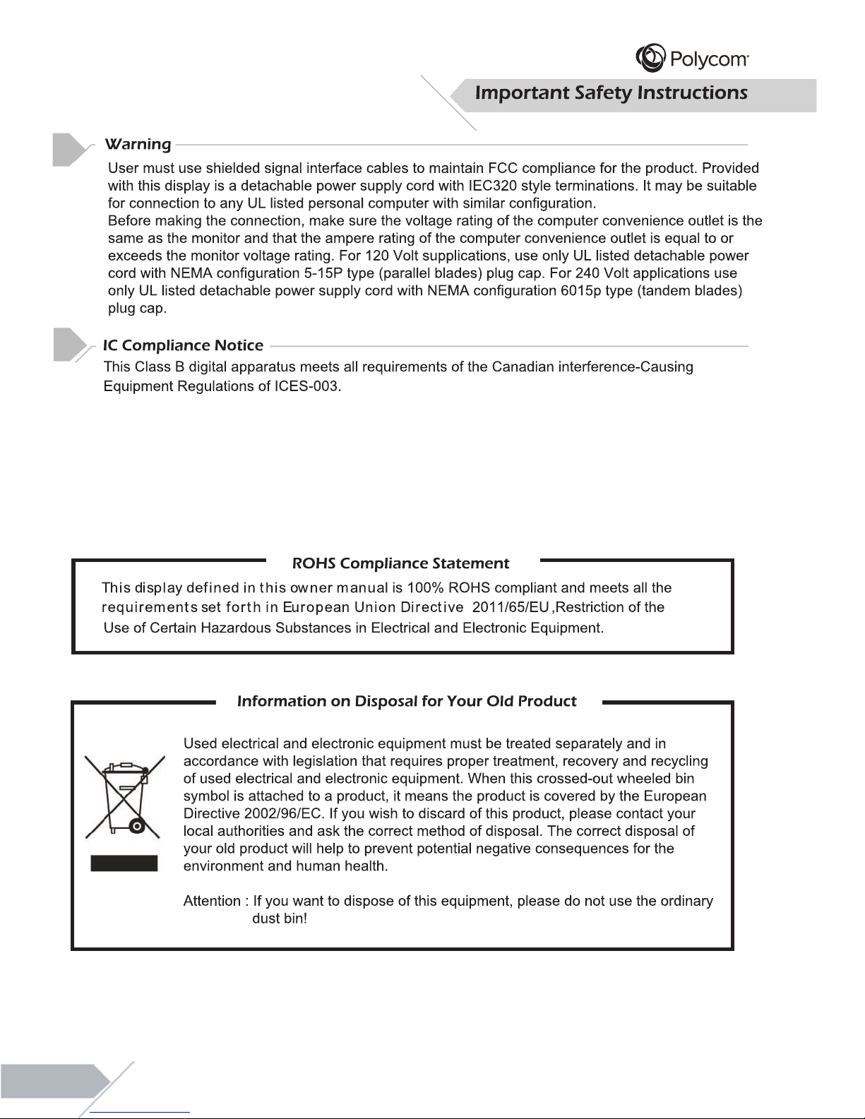
AVERTISSEMENT : Pour réduire le risque de choc électrique, ne pas retirer les
couvercles avant ou arrière. Aucune pièce n'est réparable par l'utilisateur. Confiez
l
'entretien à du personnel qualifié.
Risk of Electric Shock. Do Not Open!
Risque de choc électrique. Ne pas ouvrir!
WARNING / ATTENTION
WARNING : To reduce the risk of electric shock, do not remove the front or back covers.
No user-serviceable parts inside. Refer servicing to qualified service personnel only.
Page 4
Cleaning & Maintenance
Disconnect from the electric outlet before cleaning. Do not use liquid or aerosol cleaners. Use only
a slightly damp cloth for cleaning.
Regulatory Notice
CE Statement
The CE label on this product indicates that it complies with the 89/336/EEC directive on
electromagnetic compatibility and safety rules as defined in the 73/23/EEC, low voltage directives.
This product is protected against interferences from other electronic devices, provided that these
devices comply with the standards in force. Sporadic interferences may happen nevertheless.
FCC Statement
The Federal Communications Commission Radio Frequency Interference Statement includes
t he foll o w ing warning :
This equipment has been tested and found to comply with the limits for a Class B digital device,
pursuant to Part 15 of the FCC Rules. These limits are designed
to provide reasonable protection
against harmful interference in a residential installation.
The equipment generates, uses, and can radiate radio frequency energy and, if not installed and used
in accordance with the instructions, may cause harmful interference to radio communications. However,
there is no guarantee that interference will not occur in a particular installation. If this equipment does
cause harmful interference to radio or television receptions, which can be determined by turning the
equipment off and on, the user is encouraged to try to correct the interference by one or more of the
following measures :
Reorient or relocate the receiving antenna.
Incr ease t h e separat i o n bet ween t he equipm ent and receiver.
Connect the equipment into an outlet on a circuit different from that to which the receiver is connected.
C
onsul t t he deal er or an experienced rad i o/display technician for help.
Disconnect the unit from the main supply and refer servicing to qualified service personnel under
the following conditions :
Power cord or plug is damaged or frayed.
Liquid has been spilled into the product and/or the unit has
been exposed to water or moisture.
Unit does not operate normally when the operating instrucions are not followed. Adjust only those
controls that are covered by the operating instructions, improper adjustment of other controls may
result in damage which often requires extensive work by a qualified technician to restore the unit
to normal operation.
Unit has been dropped or the cabinet has been damaged.
Unit exhibits a distinct change in performance, indicating a need for service.
Users must use the mounting device and means provided specifically for the apparatus, or UL listed
wall mount bracket, to mount it, or the equivalent.
04
Page 5
05
Page 6
06
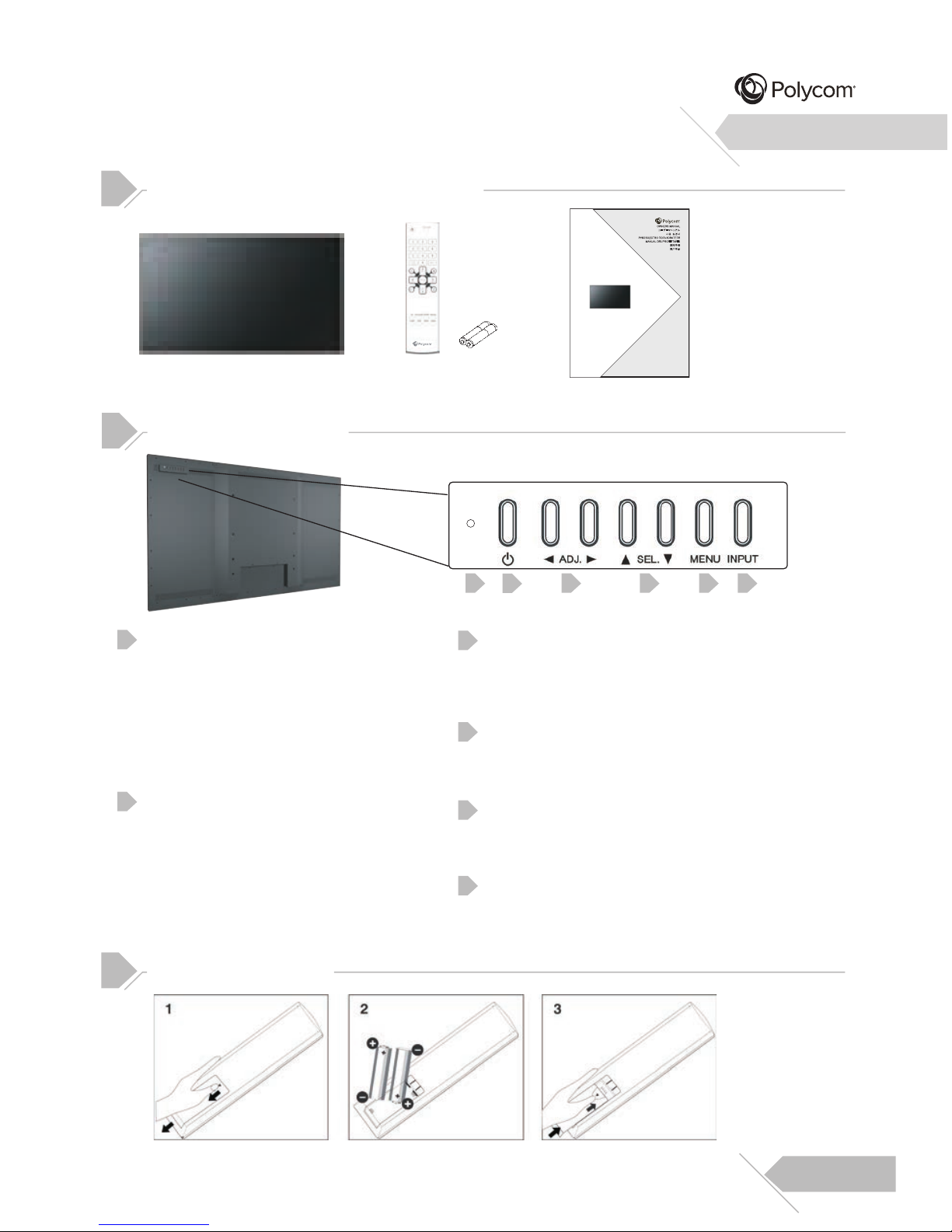
Checking the Accessories Supplied
LED Display Remote Control
with Batteries
User’s Manual
Front Panel Controls
Status LED
Orange-Standby
The LED will illuminate in orange color if
the display is at standby mode and the
main power cord is plugged into the back
of the unit.
Solid Green-Power on
Power(Standby) Button
Turns power on from standby mode.
There is a wait period between
on/standby cycles.
Adjustment Buttons
Select Buttons
Use these buttons to navigate through the On
Screen Display menu.
Menu Button
Use this button to engage the On Screen
Display menu.
Input Button
Use this button to switch between available
inputs.
Battery Installation
1
3
2
4
5
6
1 3 4 5
2
6
55” LED DISPLAY
イインチチ デディィスププレ55ン
LED
ス レ
イイ
디디스스플플레레이이
55” LED
СД-ТЕЛЕВИЗОРС
Д
ИАГОНАЛЬЮ 55"
MONITOR LED 55”
55
吋吋
LED
顯顯示示器器
55
吋吋
LED
显显示示器器
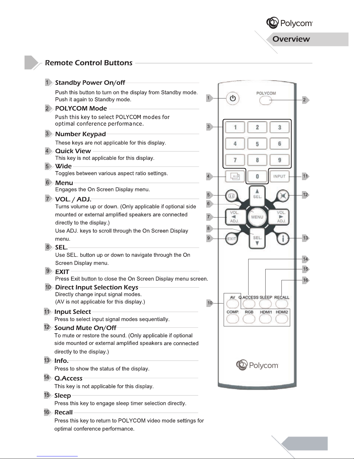
These keys serve as navigation and
adjustment keys when On Screen Display
menu is engaged.
Overview
Page 7
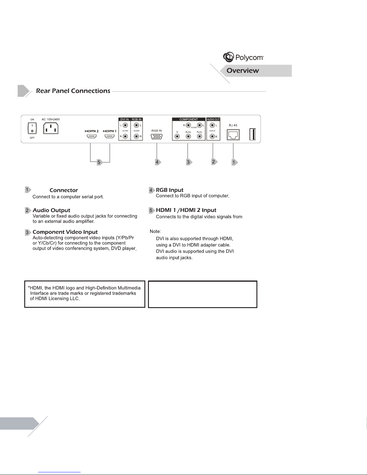
a Codec or PC video connector.
*The USB port is labelled. It is provided for after
service/engineer use ONLY.
RJ-45
07
Page 8
08
Page 9

After changing settings on the OSD menu, the new settings are confirmed automatically
shows detailed information regarding the operation status of
when OSD picture vanishes.
To access the OSD menu, press “MENU”
button on the remote control or on the
rear cover.
Navigation through the OSD menu
can be accomplished by using the
“Left/Right” or “Up/Down” keys on
remote control or rear cover.
OSD Menu
Navigation
OSD Menu
Access
121
09
Page 10

10
Page 11

PC
Connecting an External Amplifier
Connecting an External Amplified Speaker
11
Page 12

Setting Up Your Display Using Plug and Play
This display adheres to VESA Plug and Play standard to eliminate complicated and time
consuming setup of displays. This display identifies itself to the computer and automatically
sends the PC its Extended Display Identification Data (EDID) using Display Data Channel
(DDC) protocols.
How To Set Up Your Display with PC (Windows)
The display settings for a typical Windows-based computer are shown below; however,
actual screens on your computer will differ depending on the version of Windows and video
equipped with the computer. Even though the actual screen may look different from example
displayed below, basic set-up routine will apply in most cases.
Go to Window’s CONTROL PANEL by
clicking: START, SETTINGS, CONTROL
PANEL. The CONTROL PANEL Window is
displayed. Select the DISPLAY icon from this
window.
The DISPLAY PROPERTIES dialog box is
displayed. Select the SETTINGS tab to
display your computer’s video output settings.
Set the “Screen Resolution” setting to
1920x1080p PIXELS. For COLOR QUALITY,
select 24 BIT COLOR (might also be
expressed as 16 million colors).
If a vertical-frequency option exists, set the
value to 60Hz.
Click OK to complete the setting.
Note:
Both screen position and size will vary,
depending on the type of PC graphics card
and its resolution selected.
Connecting a PC (con’t)
1
2
3
4
5
Installation
1
2
3 4
1
12
Page 13

13
Page 14

14
“Left/Right” keys
Brightness.
which is optimized (and recommended) for use with POL
YCOM video conferencing systems
(and is applicable to all video inputs). As such, many of the adjustment sub-settings are “grayed-out”
and are not accessible to the user. In order to make adjustments to these settings, “CUSTOM”
picture mode must be selected.
Note that the default Picture Mode setting is set to “POLYCOM”. This setting is standard mode,
14
Page 15

Picture Quality Adjustment (RGB/HDMI Mode)
Picture Quality Adjustment (RGB Mode)
NOISE REDUCTION
HDMI RGB RANGE
until your video picture is optimal.
Increasing
15
Page 16

This display is capable of displaying a wide-screen image on the screen. However, not all
available video content fits perfectly in a wide-screen (16:9) format resulting in unused screen
space. This display is capable of displaying images in various formats that is suitable for various
types of content depending on its size.
Explanation of Various System Settings
16
remote control. Use “Right” key to select the
Setup option from the menu.
Press the “Menu” key on the front panel or
If there is no active video signal detected by the display, the display will automatically go into
sleep mode (following the duration specified in the setup menu; default setting is 1 minute).
• When using HDMI or RGB input : After the display has entered sleep mode (due to
inactivity/absence of active video), the display will automatically turn back on when the video
signal is reactivated.
• When using Component Video input : After the display has entered sleep mode, the display
will not automatically turn back on when the video signal is reactivated. It will remain in sleep
mode until the display is physically powered back on using the (display) remote control or the
control panel power switch located on the rear of the display. It is therefore recommended that
if Component Video is the preferred video stream from the codec, that ‘Power Save’ (in display
setup menu) be set to ‘Of
f’, so that the display remains powered on and will
automatically display video when the video stream is reactivated.
Page 17

Menu System
Explanation of Various System Settings
17
AUTO POWER DOWNAUTO POWER DOWN
Page 18

Additional Information
will cause a permanent
18
Page 19

Specifications
Additional Information
RJ-45
19
120 Watts Max.
1.2A Max.
Page 20

Specifications
Additional Information
20
Page 21

Specifications
Additional Information
Audio Output (only for HDMI) Audio Input +/- 3dB
The MTBF is 60,000 hrs.(back light)
1243.6mm
63.9mm
714.4mm
63.94lbs/29kgs
79.37lbs/36kgs
21
Page 22

Specifications
Additional Information
22
Page 23

Additional Information
23
RJ-45 Connection
RJ-45
RJ-45
RJ-45
Putty
Putty
Page 24

Additional Information
24
Read Data
Power On/Off
Picture Mode
Brightness
Contrast
Color
Tint
Sharpness
Color Temp
Input Select
V-Position
H-Position
Noise Reduction
Format
Backlight
Language
All Black
Mute
Recall
Polycom mode
Keypad Lock
Display Model Name
Return Model Name
Return S/W Ver.
Power On Source
Custom ColorTemp R-Gain
Custom ColorTemp G-Gain
Custom ColorTemp B-Gain
Custom ColorTemp R-Offset
Custom ColorTemp G-Offset
Custom ColorTemp B-Offset
IP Status
Static IP Configuration
REA
PWR
PTM
BRT
CON
CLR
TNT
SHP
TMP
INP
VPS
HPS
MNR
ZOM
BLT
LNG
BLK
MUT
RCL
PLC
FPL
DSP
REA
REA
POS
RGA
GGA
BGA
ROF
GOF
BOF
IPS
IPC
PWR, PTM, BRT, CON, CLR, TNT, SHP, TMP, INP, VPS, HPS, MNR, ZOM,
BLT, LNG, BLK, MUT, FPL, POS, RGA, GGA, BGA, ROF, GOF, BOF, IPS, IPC
PON=Power On, OFF=Power Off
CNM=Mild, VVD=Vivid, PLC=Polycom mode, USR=Custom
001~100
001~100
001~100
001~100
001~100
MID=Natural, HIG=Cool, 65D=Warm, USR=Custom
CP1=COMP, RG1=RGB, HM1=HDMI1, HM2=HDMI2
001~100 (RGB only)
001~100 (RGB only)
OFF=Off, LOW=Low, MID=Middle, HIG=High (HDMI, COMP only)
WID=16:9, NOR=4:3 with black bars
LIG=Light, PRO=Proper, SOF=Soft
ENG=English, SPA=Spanish, FFR=French, ITA=Italian, DEU=German
SWE=Swedish
BON=All Black, OFF=Return
OFF=UnMute, MON=Mute
000
000
FO1=Lock, OFF=Unlock
INF (Example : DSP : INF RCV CFM) (PME55MA Display on screen)
INF (Example : REA : INF RCV PME55MA CFM)
VER (Example : REA : VER RCV PME55MA-140107 CFM)
OFF=Normal(Last Memory), CP1=COMP, RG1=RGB, HDM=HDMI1, HM2=HDMI2
000~255
000~255
000~255
000~255
000~255
000~255
DYN=Dynamic, STA=Static
xxx.xxx.xxx.xxx xxx.xxx.xxx.xxx xxx.xxx.xxx.xxx (IP Mask Getway)
(Example : IPC:192.168.0.101 255.255.255.0 192.168.0.1 RCV)
Page 25

Dimensional Drawings
Additional Information
Item Color Scheme
Outer Front Bezel
Black
25
Page 26

Additional Information
26
PME55MA EXPLODED VIEW (MECHANICAL PARTS)
ITEM PART NO. DESCRIPTION UNIT REMARKS
1 SET
2 TLABD2003Y1B---
3 TLABM1920Y1----
4 YTAPEQ075T900--
5 SSAKH0203Y1---B
6 SP
AKA0918Y1----
8 SP
AKC0962Y1----
7
10 JHNDP0020Y1----
11 YTIE-P155Y1600-
9 TLABD1142Y1---A
TINSE2240Y1----
YRC-294POL
YCOMC
RBA
TB0226Y1DD--
SSAKD0003Y1-T-C
1
1
1
1
1
1
1
1
1
1
1
ACCESSOR
Y
KIT
ACCESSORY KIT
ACCESSORY KIT
ACCESSORY KIT
1
1
1
PME55MA
TAPE
MODEL LABEL
PE BAG
SERIAL LABEL
BATTERY
DATA BAG
USER MANUAL
EPE FOAM
WRAPPING
CASE HANDLE
BAR CODE
REMOTE CONTROL
CAR
TON
 Loading...