

Page 1

Polycom® VBP™ 5300LF2 System
Hardware Guide
June 2011 | 3725-73553-001A
Page 2

5300LF2 Hardware Guide
1
Trademark Information
Polycom®, the Polycom “Triangles” logo, and the names and marks associated with Polycom’s products are trademarks and/or service marks of
Polycom, Inc., and are registered and/or common-law marks in the United States and various other countries.
All other trademarks are the property of their respective owners.
© 2010 Polycom, Inc. All rights reserved.
Polycom, Inc.
4750 Willow Road
Pleasanton, CA 94588-2708
USA
No part of this document may be reproduced or transmitted in any form or by any means, electronic or mechanical, for any purpose, without the
express written permission of Polycom, Inc. Under the law, reproducing includes translating into another language or format.
As between the parties, Polycom, Inc., retains title to and ownership of all proprietary rights with respect to the software contained within its
products. The software is protected by United States copyright laws and international treaty provision. Therefore, you must treat the software like
any other copyrighted material (e.g., a book or sound recording).
Every effort has been made to ensure that the information in this document is accurate. Polycom, Inc., is not responsible for printing or clerical
errors. Information in this document is subject to change without notice.
Page 3

5300LF2 Hardware Guide
2
5300LF2 VBP-E Series Physical connections and LED’s
A
Erase
1 Click - Nothing
2 Clicks - Reset CLI password and restarts the system
3 Clicks - Restore to factory default
B
Port 3 - Management interface
1 x 10/100/1000 Mbps Ethernet port for optional management network
connectivity, this interface must not be on the same network as the WAN or LAN
subnets. This network cannot be within a subnet contained in a “Route”
statement
C
Port 2 - WAN interface
1 x 10/100/1000 Mbps Ethernet port for connectivity to the WAN or Internet
network connectivity
Default IP: none
D
Port 1 - LAN interface
1 x 10/100/1000 Mbps Ethernet port for LAN network connectivity
Default IP: 192.168.1.1
E
Console
1 x RS-232 8 pin modular console port for management – 9600-N-8-1 NONE for
flow control – 8 pin modular to DB9 cable provided in system box
F
USB
Currently not used
Page 4
5300LF2 Hardware Guide
3
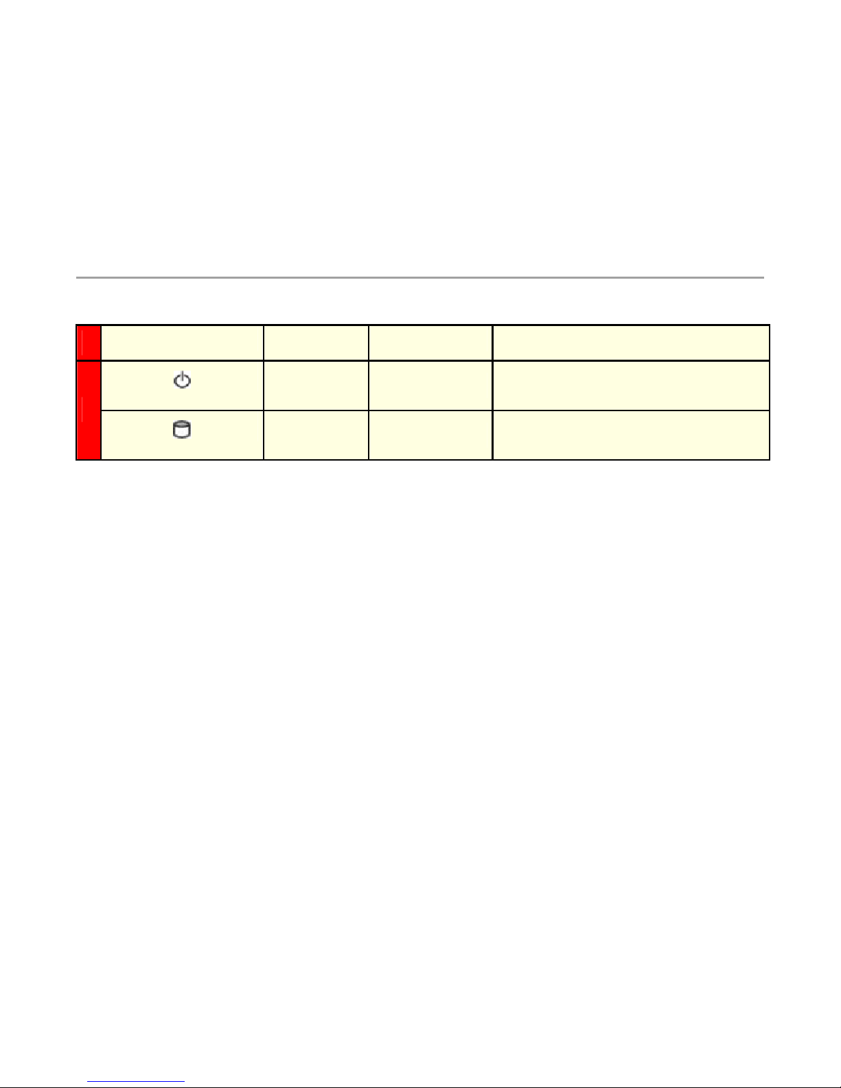
Symbol Function Color Signal
Power Status Green
Off – No Power, the system is off
On – Power is good, the system is on
G
Data Status Red
Off – No data access to the IDE drive
On – Data is being written to the IDE drive
Page 5
5300LF2 Hardware Guide
4
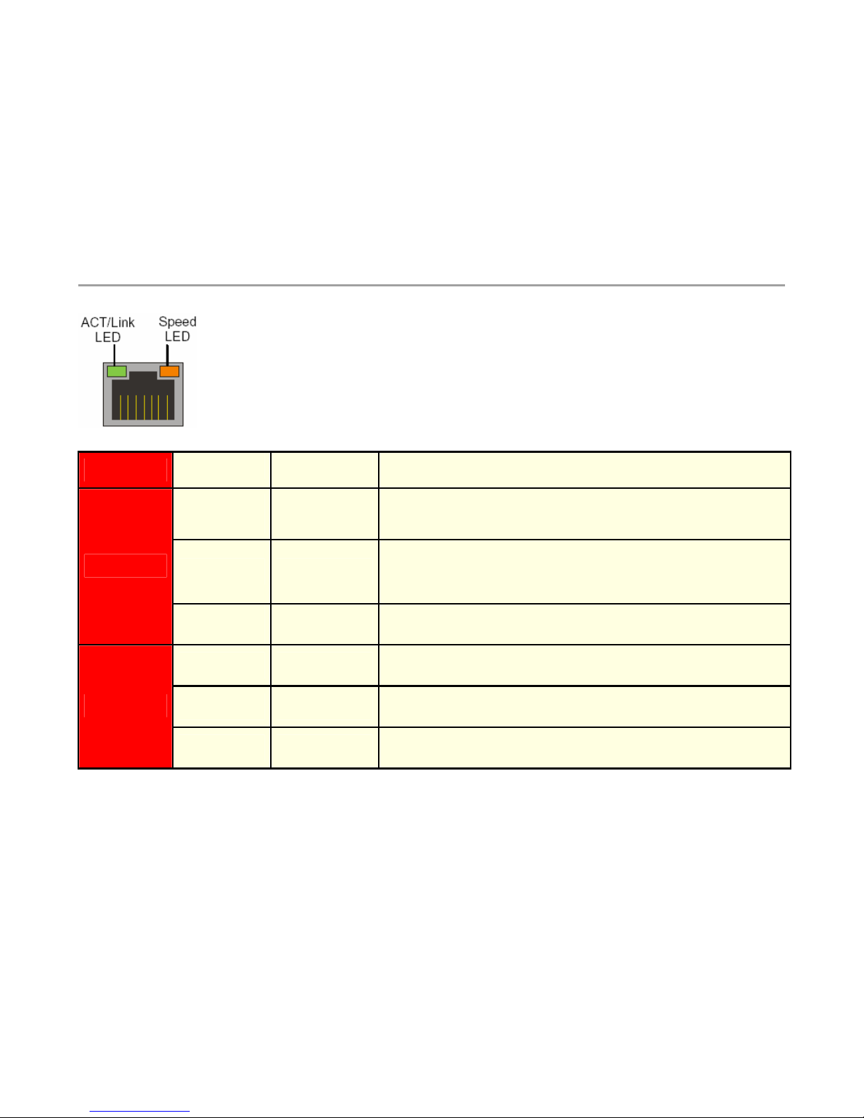
Label
Color Indication Status
Green or
other
On
1: Ethernet port is receiving power
2: Good link between the Ethernet port and the connected switch
Off
1: The adapter and switch are not receiving power
2: No connection between both ends of the network cable, check cable,
replace cable.
ACK/LINK
Green or
other
Flashing
The adapter is sending and receiving network data. The frequency of the
flashing varies with the amount of data being transferred.
Yellow On
ACK/LINK LED must be on. This LED will show the system operating at
1000 Mbps
Green On
ACK/LINK LED must be on. This LED will show the system operating at
100 Mbps
Speed
Off
ACK/LINK LED must be on. This LED will show the system operating at
10 Mbps
Page 6
5300LF2 Hardware Guide
5
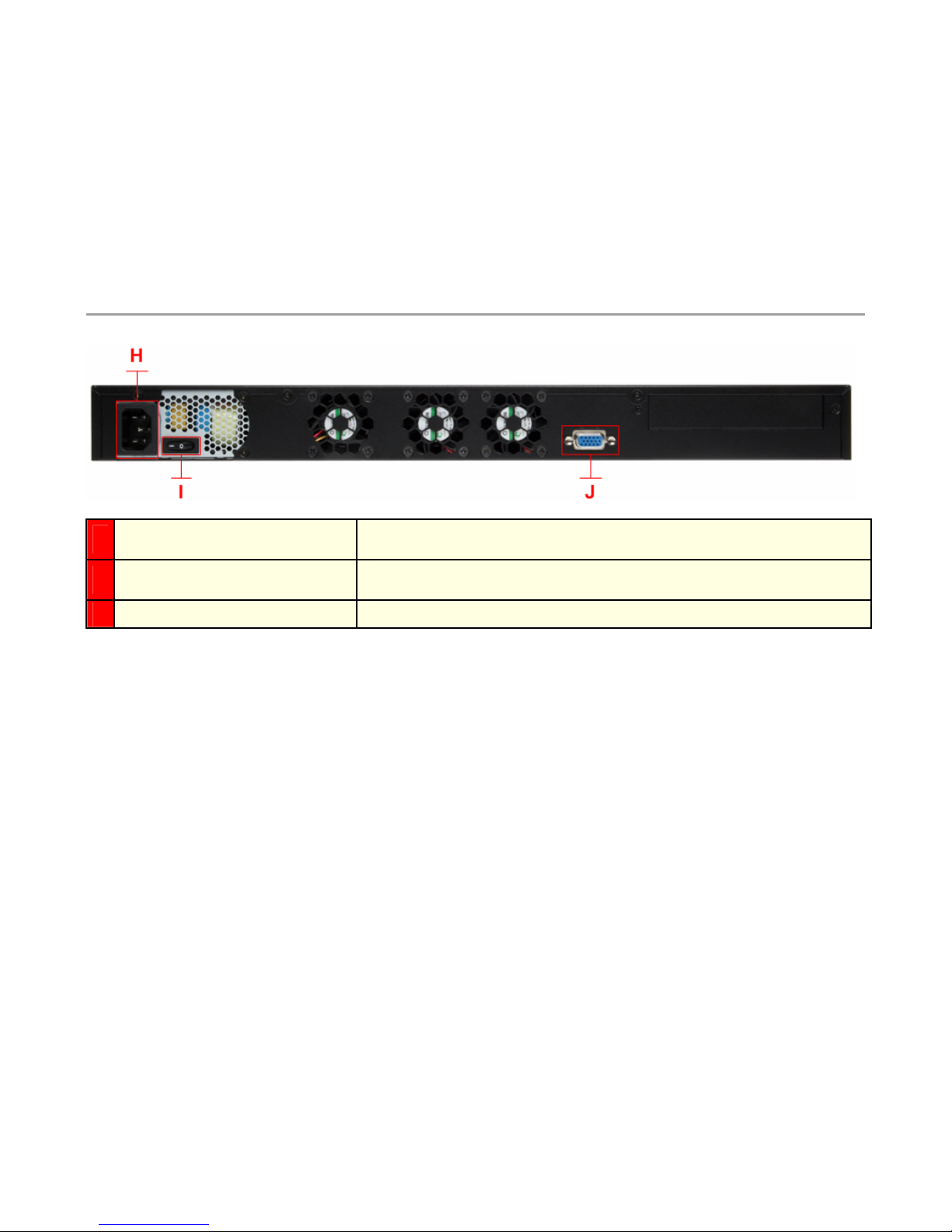
H
Input Power Socket
Accepts 3-pin Shroud Female plug for input power
I
On/Off Switch
Used to turn the system on and off
J
VGA Currently not used
Page 7

5300LF2 Hardware Guide
6
Connecting to the 5300LF2 VBP-E Series for the First Time
The VBP Series appliance is shipped with a pre-configured IP address on Port 1 of 192.168.1.1
1. Connect the 3-pin Shroud female plug of the power cord into the input power socket in the system shown as (H) in the above figures and
the other end to a wall AC outlet.
2. Turn the system power on by pressing on the top part of the power switch shown as (I) in the above figures.
3. Connect a computer using an IP address of 192.168.1.2 and subnet mask of 255.255.255.0 to Port 1 shown as (D) in the above figures
with either a Ethernet switch or a Ethernet cable wired directly to the computer.
4. Launch a Web browser on the computer and enter the http://192.168.1.1
Press Return. The main configuration menu appears - enter
the username root and the password default.
5. The EULA license agreement will now be displayed. After reading the license agreement, click “I agree” at the bottom to continue
configuring the system.
Configure the Network parameters as defined in the Configuration Guide contained on the VBP Documentation Library CD provided with the
system. The Configuration Guide is also available on the Polycom Web site.
Page 8

5300LF2 Hardware Guide
7
5300LF2 VBP-ST series Physical connections and LED’s
A
Erase
1 Click - Nothing
2 Clicks - Reset CLI password and restarts the system
3 Clicks - Restore to factory default
B
Port 3 - Management interface
1 x 10/100/1000 Mbps Ethernet port for optional management network
connectivity, this interface must not be on the same network as the WAN or LAN
subnets. This network cannot be within a subnet contained in a “Route” statement
C
Port 2 - Provider interface
1 x 10/100/1000 Mbps Ethernet port for connectivity to the Provider or LAN
network connectivity
Default IP: none
D
Port 1 - Subscriber interface
1 x 10/100/1000 Mbps Ethernet port for Subscriber or WAN/Internet network
connectivity
Default IP: 192.168.1.1
E
Console
1 x RS-232 8 pin module console port for management – 9600-N-8-1 NONE for
flow control – 8 pin modular to DB9 cable provided in system box
F
USB
Not used
Page 9

5300LF2 Hardware Guide
8
Symbol Function Color Signal
Power Status Green
Off – No Power - the system is off
On – Power is good - the system is on
G
Data Status Red
Off – No data access to the IDE drive
On – Data is being written to the IDE drive
Page 10

5300LF2 Hardware Guide
9
Label
Color Indication Status
Green or
other
On
1: Ethernet port is receiving power
2: Good link between the Ethernet port and the connected switch
Off
1: The adapter and switch are not receiving power
2: No connection between both ends of the network cable, check cable,
replace cable.
ACK/LINK
Green or
other
Flashing
The adapter is sending and receiving network data. The frequency of the
flashing varies with the amount of data being transferred.
Yellow On
ACK/LINK LED must be on. This LED will show the system operating at
1000 Mbps
Green On
ACK/LINK LED must be on. This LED will show the system operating at
100 Mbps
Speed
Off
ACK/LINK LED must be on. This LED will show the system operating at
10 Mbps
Page 11

5300LF2 Hardware Guide
10
H
Input Power Socket
Accepts 3-pin Shroud Female plug for input power
I
On/Off Switch
Used to turn the system on and off
J
VGA Currently not used
Page 12

5300LF2 Hardware Guide
11
Connecting to the 5300LF2 VBP-ST Series for the First Time
The VBP Series appliance is shipped with a pre-configured IP address on Port 1 of 192.168.1.1
1. Connect the 3-pin Shroud female plug of the power cord into the input power socket in the system shown as (H) in the above figures and
the other end to a wall AC outlet.
2. Turn the system power on by pressing on the top part of the power switch shown as (I) in the above figures.
3. Connect a computer using an IP address of 192.168.1.2 and subnet mask of 255.255.255.0 to Port 1 shown as (D) in the above figures
with either a Ethernet switch or a Ethernet cable wired directly to the computer.
4. Launch a Web browser on the PC and enter the http://192.168.1.1
Press Return. The main configuration menu appears - enter the
username root and the password default.
5. The EULA license agreement will now be displayed. After reading the license agreement, click “I agree” at the bottom to continue
configuring the system.
Configure the Network parameters as defined in the Configuration Guide contained on the VBP Documentation Library CD provided with the
system. The Configuration Guide is also available on the Polycom Web site.
Page 13

5300LF2 Hardware Guide
12
Specifications and Certifications
Ethernet ports 3 x 10/100/1000 Ethernet
Serial Ports
1 x RS-232 8 pin modular
Dimensions
W: 443mm / 17.4” x D: 292mm / 11.5” x H: 44mm / 1.73” (1U)
Weight 13 lbs
Power 100/240v VAC - auto-selecting, 50 to 60 Hz with 200W output – BTU/h = 682
Warranty 1 Year
Environmental
Requirement
Operating Temperature: 0° to 40°C
Relative Humidity: 10% to 90%
Acoustics: < 55db
Shock: 0.5 Sine shock,10G peak, 10 +/- 3ms on (X,Y,Z) axis
Vibration: 0.5G (Peak) / 5~500 Hz, 2hours at each of Z axis
BTU/h = 682
Certifications
RoHS Compliant
WEEE Compliant
Safety
CE, cUL
Emissions
FCC Part 15 Class A
ICES-003
VCCI Class A
KCC
CCC
C-tick
Immunity
CE
MTBF
78,120 (hrs)
Page 14

5300LF2 Hardware Guide
13
Physical Installation
The 5300LF2 is designed for desktop or rack mount installation. Observe the following guidelines when installing the system:
• Always verify that the AC cord is disconnected from a power source prior to installation.
• Ensure that the installation site has adequate air circulation and meets the minimum operating conditions for the system as
specified in the Specifications and Certifications section of this document.
Desktop or rack shelf Installation
• Remove the 5300LF2 and accessories from the shipping container.
• Place the 5300LF2 on a flat, dry surface such as a desktop, shelf or tray.
Rack- Mount Installation
• Remove the rack mount kit supplied in the shipping container and install the kit on the 5300LF2
• Mount the completed assembly into your 19” equipment rack.
Connecting the Power and Cables
The 5300LF2 comes with an AC power cord for connecting the unit to the AC outlet.
Warning: Always connect the AC power cord to an AC outlet suitable for the power supply per the Power specifications listed in this
document in order to reduce the risk of damage to the 5300LF2 power supply.
• Connect one end of the AC power cord to the 5300LF2 input power socket and the other one to the AC outlet. Connecting the AC
power cord to the input power socket of the 5300LF2 may require a little force to get the plug properly positioned
Caution: Secure the AC power cord using a fastener or tie wrap to a cable management system to unsure the 5300LF2 does not hang
from the AC outlet.
• If connecting to an Internet router, Internet DMZ switch, cable modem or DSL modem, then connect the Ethernet cable to the
Ethernet WAN/Subscriber port on 5300LF2 and the other end to the WAN device.
Page 15

5300LF2 Hardware Guide
14
Compliance and Compatibility for the VBP 5300LF2 Converged Network Appliance
Warning
This is a Class A product. In a domestic environment, this product may cause radio interference in which case the user may be required to take
adequate measures.
USA AND CANADIAN NOTICES
FCC Notice
Class A Digital Device or Peripheral
This equipment has been tested and found to comply with the limits for a Class A digital device, pursuant to Part 15 of the FCC Rules. These limits
are designed to provide reasonable protection against harmful interference when the equipment is operated in a commercial environment. This
equipment generates, uses, and can radiate radio frequency energy and, if not installed and used in accordance with the instruction manual, may
cause harmful interference to radio communications. Operation of this equipment in a residential area is likely to cause harmful interference in
which case the user will be required to correct the interference at his own expense.
In accordance with Part 15 of the FCC rules, the user is cautioned that any changes or modifications not expressly approved by Polycom Inc.
could void the user's authority to operate this equipment.
The socket outlet to which this apparatus is connected must be installed near the equipment and must always be readily accessible.
Part 15 FCC Rules
This device complies with part 15 of the FCC rules. Operation is subject to the following two conditions:
1) This device may not cause harmful interference, and
2) this device must accept any interference received, including interference that may cause undesired operation.
Industry Canada (IC)
This Class [A] digital apparatus complies with Canadian ICES-003.
Cet appareil numerique de la Classe [A] est conforme à la norme NMB-003 du Canada.
The Industry Canada label identifies certified equipment. This certification means that the equipment meets telecommunications network
protective, operational and safety requirements as prescribed in the appropriate Terminal Equipment Technical Requirements document(s). The
Department does not guarantee the equipment will operate to the user's satisfaction.
Before installing this equipment, users should ensure that it is permissible to be connected to the facilities of the local telecommunications
company. The equipment must also be installed using an acceptable method of connection. The customer should be aware that compliance with
Page 16

5300LF2 Hardware Guide
15
the above conditions may not prevent degradation of service in some situations. Repairs to certified equipment should be coordinated by a
representative designated by the supplier. Any repairs or alterations made by the user to this equipment, or equipment malfunctions, may give the
telecommunications company cause to request the user to disconnect the equipment.
Users should ensure for their own protection that the electrical ground connections of the power utility, telephone lines and internal metallic water
pipe system, if present, are connected together. This precaution may be particularly important in rural areas.
Caution: Users should not attempt to make such connections themselves, but should contact the appropriate electric inspection authority, or
electrician, as appropriate.
The Ringer Equivalence Number (REN) assigned to each relevant terminal device provides an indication of the maximum number of terminals
allowed to be connected to a telephone interface. The termination on an interface may consist of any combination of devices subject only to the
requirement that the sum of the RENs of all the devices does not exceed 5.
The REN of this equipment is either marked on the unit or included in the new style USA FCC registration number. In the case that the REN is
included in the FCC number, the user should use the following key to determine the value:
The FCC number is formatted as US:AAAEQ#TXXX.
# is the Ringer Equivalence Number without a decimal point (e.g. REN of 1.0 will be shown as 10, REN of 0.3 will be shown as 03). In the case of
a Z ringer, ZZ shall appear. In the case of approved equipment without a network interface or equipment not to be connected to circuits with
analog ringing supplied, NA shall appear.
The REN is useful to determine the quantity of devices that may be connected to the telephone line. Excessive RENs on the telephone line may
result in the devices not ringing in response to an incoming call. In most, but not all areas, the sum of RENs of all devices that may be connected
to a line, is determined by the total RENs, contact the local telephone company.
CLASS A STATEMENTS
Japan
Page 17

5300LF2 Hardware Guide
16
Korea
China
Page 18

5300LF2 Hardware Guide
17
EEA Regulatory Notices
CE Mark R & TTE Directive
This Polycom VBP system has been marked with the CE mark. This mark indicates compliance with EEC Directives 89/336/EEC, 73/23/EEC
1999/5/EC. A full copy of the Declaration of Conformity can be obtained from Polycom Ltd., 270 Bath Road, Slough UK SL1 4DX
Declaration of Conformity:
English:
Hereby, Polycom, declares that this VBP 5300LF2 is in
compliance with the essential requirements and other relevant provisions of
Directive 1999/5/EC.
Česky
[Czech]:
Polycom tímto prohlašuje, že tento VBP 5300LF2 je ve shodě se
základními požadavky a dalšími příslušnými ustanoveními směrnice 1999/5/ES.
Dansk
[Danish]:
Undertegnede Polycom erklærer herved, at følgende udstyr
VBP 5300LF2 overholder de væsentlige krav og øvrige relevante
krav i direktiv 1999/5/EF.
Deutsch
[German]:
Hiermit erklärt Polycom, dass sich das Gerät VBP 5300LF2 in
Übereinstimmung mit den grundlegenden Anforderungen und den übrigen
einschlägigen Bestimmungen der Richtlinie 1999/5/EG befindet.
Eesti
[Estonian]:
Käesolevaga kinnitab Polycom seadme VBP 5300LF2 vastavust direktiivi
1999/5/EÜ põhinõuetele ja
nimetatud direktiivist tulenevatele teistele asjakohastele sätetele.
Español
[Spanish]:
Por medio de la presente Polycom declara que el VBP 5300LF2 cumple con los
requisitos esenciales y cualesquiera otras disposiciones
aplicables o exigibles de la Directiva 1999/5/CE.
Ελληνική
[Greek]:
ΜΕ ΤΗΝ ΠΑΡΟΥΣΑ Polycom ∆ΗΛΩΝΕΙ ΟΤΙ VBP 5300LF2
ΣΥΜΜΟΡΦΩΝΕΤΑΙ ΠΡΟΣ ΤΙΣ ΟΥΣΙΩ∆ΕΙΣ ΑΠΑΙΤΗΣΕΙΣ ΚΑΙ ΤΙΣ ΛΟΙΠΕΣ
ΣΧΕΤΙΚΕΣ
∆ΙΑΤΑΞΕΙΣ ΤΗΣ Ο∆ΗΓΙΑΣ 1999/5/ΕΚ.
Français
[French]:
Par la présente Polycom déclare que l'appareil VBP 5300LF2 est
conforme aux exigences essentielles et aux autres dispositions pertinentes de
Page 19

5300LF2 Hardware Guide
18
la
directive 1999/5/CE.
Italiano
[Italian]:
Con la presente Polycom dichiara che questo VBP 5300LF2
è conforme ai requisiti essenziali ed alle altre disposizioni pertinenti stabilite
dalla
direttiva 1999/5/CE.
Latviski
[Latvian]:
Ar šo Polycom deklarē, ka VBP 5300LF2 atbilst Direktīvas 1999/5/EK
būtiskajām prasībām un
citiem ar to saistītajiem noteikumiem.
Lietuvių
[Lithuanian]: Šiuo Polycom deklaruoja, kad šis VBP 5300LF2 atitinka
esminius reikalavimus ir kitas 1999/5/EB Direktyvos nuostatas.
Nederlands
[Dutch]:
Hierbij verklaart Polycom dat het toestel VBP 5300LF2 in
overeenstemming is met de essentiële eisen en de andere relevante bepalingen
van richtlijn 1999/5/EG.
Malti
[Maltese]:
Hawnhekk, Polycom, jiddikjara li dan VBP 5300LF2
jikkonforma mal-ħtiġijiet essenzjali u ma provvedimenti oħrajn relevanti li hemm
fid-Dirrettiva 1999/5/EC.
Magyar
[Hungarian]:
Alulírott, Polycom nyilatkozom, hogy a VBP 5300LF2 megfelel a vonatkozó
alapvetõ követelményeknek és az 1999/5/EC irányelv egyéb elõírásainak.
Polski
[Polish]:
Niniejszym Polycom oświadcza, że VBP 5300LF2 jest zgodny z
zasadniczymi wymogami oraz pozostałymi stosownymi postanowieniami
Dyrektywy 1999/5/EC
Português
[Portuguese]:
Polycom] declara que este VBP 5300LF2 está conforme com
os requisitos essenciais e outras disposições da Directiva 1999/5/CE.
Slovensko
[Slovenian]:
Polycom izjavlja, da je ta VBP 5300LF2 v skladu z bistvenimi zahtevami
in ostalimi relevantnimi določili direktive 1999/5/ES.
Slovensky
Page 20

5300LF2 Hardware Guide
19
[Slovak]: Polycom týmto vyhlasuje, že VBP 5300LF2 spĺňa základné požiadavky
a všetky príslušné ustanovenia Smernice 1999/5/ES.
Suomi
[Finnish]:
Polycom vakuuttaa täten että VBP 5300LF2 tyyppinen laite on direktiivin
1999/5/EY oleellisten vaatimusten
ja sitä koskevien direktiivin muiden ehtojen mukainen.
Svenska
[Swedish]:
Härmed intygar Polycom att denna VBP 5300LF2 står I överensstämmelse
med de väsentliga egenskapskrav och övriga relevanta bestämmelser som
framgår av direktiv 1999/5/EG.
Íslenska
(Icelandic):
Hér með lýsir Polycom yfir því að VBP 5300LF2 er í
samræmi við grunnkröfur og aðrar kröfur, sem gerðar eru í tilskipun 1999/5/EC
Norsk
[Norwegian]:
Polycom erklærer herved at utstyret VBP 5300LF2 er i
samsvar med de grunnleggende krav og øvrige relevante krav i direktiv
1999/5/EF
.
Hardware Warranty
For a period of one (1) year after shipment of the Product, Polycom warrants that such Hardware will substantially conform to Polycom’s published
specifications for such Hardware on the date of order if properly used in accordance with procedures described in the documentation supplied by
Polycom. End-user shall notify Polycom of any nonconformance during the warranty period, obtain a return authorization for the nonconforming
Hardware from Polycom, and return the nonconforming Hardware to Polycom’s designated repair facility, freight prepaid, with a statement
describing the nonconformity. Polycom’s exclusive obligations with respect to nonconforming Hardware shall be, at Polycom’s option, to advance
replace such Hardware, if it is determined to be defective, or to refund to End-user the purchase price paid for the Product. Advance replacement
units are shipped same business day for next-day delivery (within the US) when hardware failure is determined by 1pm PST. Failed components
must be returned to Polycom within 14 days or End-user will be charged for new product purchase.
Restriction of Hazardous Substances Directive (RoHS)
Polycom products are RoHS compliant, which means we have eliminated or brought to within acceptable limits: Lead, Mercury, Cadmium,
Hexavalent Chromium, Polybrominated Biphenyls, and Polybrominated Diphenylethers. For more information please contact
TypeApproval@polycom.com
.
Page 21

5300LF2 Hardware Guide
20
End of Life Products
Polycom encourages you to recycle your end-of-life Polycom products in an environmentally considerate way. In accordance with the
requirements of the European Waste Electronic and Electrical Equipment (WEEE) Directive, all Polycom products are marked with the crossed
wheelie bin symbol shown below. Products that carry this symbol should be not be disposed of in the household or general waste stream. Detail of
the options open to you and the guidance on the requirements for the recycling and environmentally considerate disposal of your end of life
Polycom products can be found at http://www.polycom.com/WEEE.
 Loading...