

Page 1

VIEW Certified Configuration Guide
Cisco
2100/4400/5500 Series WLC (Wireless LAN Controller),
WiSM (Wireless Services Module) and 3750G Integrated WLC
with 1100, 1130, 1140, 1200, 1230, 1240, 1250 APs
October 2010 Edition
1725-36192-001
Version H
Page 2

VIEW Certified Configuration Guide
2
Patent Information
The accompanying product is protected by one
or more US and foreign patents and/or pending
patent applications held by Polycom, Inc.
Copyright Notice
© 2010, Polycom, Inc. All rights reserved.
POLYCOM®, the Polycom "Triangles" logo and
the names and marks associated with Polycom's
products are trademarks and/or service marks
of Polycom, Inc. and are registered and/or
common law marks in the United States and
various other countries. All other trademarks
are property of their respective owners. No
portion hereof may be reproduced or
transmitted in any form or by any means, for
any purpose other than the recipient's personal
use, without the express written permission of
Polycom.
All rights reserved under the International and
pan-American copyright Conventions.
No part of this manual, or the software
described herein, may be reproduced or
transmitted in any form or by any means, or
translated into another language or format, in
whole or in part, without the express written
permission of Polycom, Inc.
Do not remove (or allow any third party to
remove) any product identification, copyright or
other notices.
Every effort has been made to ensure that the
information in this document is accurate.
Polycom, Inc. is not responsible for printing or
clerical errors. Information in this document is
subject to change without notice and does not
represent a commitment on the part of Polycom,
Inc.
Notice
Polycom, Inc. has prepared this document for
use by Polycom personnel and customers. The
drawings and specifications contained herein
are the property of Polycom and shall be neither
reproduced in whole or in part without the prior
written approval of Polycom, nor be implied to
grant any license to make, use, or sell equipment
manufactured in accordance herewith.
Polycom reserves the right to make changes in
specifications and other information contained
in this document without prior notice, and the
reader should in all cases consult Polycom to
determine whether any such changes have been
made.
NO REPRESENTATION OR OTHER
AFFIRMATION OF FACT CONTAINED IN
THIS DOCUMENT INCLUDING BUT NOT
LIMITED TO STATEMENTS REGARDING
CAPACITY, RESPONSE-TIME
PERFORMANCE, SUITABILITY FOR USE, OR
PERFORMANCE OF PRODUCTS DESCRIBED
HEREIN SHALL BE DEEMED TO BE A
WARRANTY BY POLYCOM FOR ANY
PURPOSE, OR GIVE RISE TO ANY LIABILITY
OF POLYCOM WHATSOEVER.
Contact Information
Please contact your Polycom Authorized
Reseller for assistance.
Polycom, Inc.
4750 Willow Road,
Pleasanton, CA 94588
http://www.polycom.com
PN: 1725-36192-001_H
Page 3

Cisco Wireless LAN Controllers with 1100, 1130, 1140, 1200, 1230, 1240, 1250 APs
Contents
Overview .................................................................................................... 4
Certified Product Summary ..............................................................4
Known Limitations .............................................................................5
Polycom References ............................................................................5
Product Support ..................................................................................6
Section 1: Configuration for SVP Operation ........................................... 7
Network Topology ..............................................................................7
Configuring a New Controller Starting from Factory
Defaults .................................................................................................7
Connecting to the Controller Via a Browser ...................................8
Installing Software ..............................................................................9
Controller Setup ..................................................................................9
Connecting APs .................................................................................10
AP Configuration ..............................................................................11
Setting up the SSID ...........................................................................17
Section 2: Configuration for Wi-Fi Standard QoS or CCXv4
Operation ................................................................................................. 23
Network Topology ............................................................................23
Configuring a New Controller Starting from Factory
Defaults ...............................................................................................24
Connecting to the Controller Via a Browser .................................24
Installing Software ............................................................................25
Controller Setup ................................................................................26
Connecting APs .................................................................................27
AP Configuration ..............................................................................28
PN: 1725-36192-001_H 3
Setting up the SSID ...........................................................................37
Page 4

4
Overview
Manufacturer:
Cisco Systems: www.cisco.com
Certified products:
Controllers:
2100, 4400, 5500 Series WLC
(Wireless LAN Controller)
3750G Integrated WLC
WiSM (Wireless Services
Module)
APs:
1100
1130
1140
1200
1230
1240
1250
AP Radio(s):
2.4 GHz (802.11b/g/n), 5 GHz (802.11a/n)
Security:
WPA-PSK, WPA2-PSK, WPA2-Enterprise (EAP-FAST
and PEAPv0/MSCHAPv2) with CCKM (Cisco Client Key
Management)
QoS:
SVP, Wi-Fi Standard QoS, CCXv4
AP and WLC software version
tested:
5.2.193.0†
6.0.199.4††
Handset models tested:
SpectraLink 8020/8030 Wireless Telephone*
Radio mode:
802.11b & b/g mixed
802.11a
Meets VIEW minimum call
capacity per AP:
8 calls (SVP)
6 (Wi-Fi Standard QoS)**
6 (CCX)**
12 calls (SVP)
8 (Wi-Fi Standard QoS)**
8 (CCX)**
Network topology:
Switched Ethernet (recommended)
VIEW Certified Configuration Guide
Polycom’s Voice Interoperability for Enterprise Wireless (VIEW)
Certification Program is designed to ensure interoperability and high
performance between SpectraLink Wireless Telephones and WLAN
infrastructure products.
The products listed below have been thoroughly tested in Polycom’s
lab and have passed VIEW Certification. This guide describes the
configuration of Cisco 2100/4400/5500 Series WLC (Wireless LAN
Controller), WiSM (Wireless Services Module) and 3750G Integrated
WLC with 1100, 1130, 1140, 1200, 1230, 1240, 1250 APs with
SpectraLink 8020/8030 Wireless Telephones.
Certified Product Summary
† Push-to-talk (PTT) audio quality may be impaired on Cisco 1140 and 1250 802.11n APs with
version 5.2.193.0 certified software. All customers requiring PTT using these models should pilot
test this feature at their deployment site.
†† Screen captures included in this document are for Cisco software version 6.0.199.4. Refer to
Version D of this guide for screen captures for software version 5.2.193.0.
PN: 1725-36192-001_H
Page 5

Cisco Wireless LAN Controllers with 1100, 1130, 1140, 1200, 1230, 1240, 1250 APs
*SpectraLink handset models 8020/8030 and their OEM derivates are verified compatible with
the WLAN hardware and software identified in the table. Throughout the remainder of this
document they will be referred to collectively as “SpectraLink Wireless Telephones” or
“handsets”.
** ONLY Release 3.0 capable handsets support WPA2-Enterprise, Wi-Fi Standard QoS, and
CCXv4. Release 3.0 is not be available for Polycom handsets connecting to traditional PBXs.
Known Limitations
Push-to-talk (PTT) audio quality may be impaired on Cisco 1140
and 1250 802.11n APs with version 5.2.193.0 certified software.
All customers requiring PTT with these models should pilot test
this feature at their deployment site.
Heavy multicast, broadcast or push-to-talk (PTT) traffic may
impair voice quality.
Polycom References
Please refer to the Polycom Deploying Enterprise-Grade Wi-Fi Telephony
white paper. This document covers the security, coverage, capacity
and QoS considerations necessary for ensuring excellent voice quality
with enterprise Wi-Fi networks.
For more detailed information on wireless LAN layout, network
infrastructure, QoS, security and subnets, please see the Best Practices
Guide for Deploying SpectraLink 8020/8030 Wireless Telephones. This
document identifies issues and solutions based on Polycom’s
extensive experience in enterprise-class Wi-Fi telephony. It provides
recommendations for ensuring that a network environment is
adequately optimized for use with SpectraLink 8020/8030 Wireless
Telephones.
These two white papers are available at:
http://www.polycom.com/products/voice/wireless_solutions/wifi
_communications/handsets/spectralink_8020_wireless.html
PN: 1725-36192-001_H 5
Page 6

6
Product Support
This document does not cover the steps involved in converting
autonomous APs to Lightweight mode such that they can be
controlled by the Cisco WLCs.
Please contact Cisco's Customer Support at www.cisco.com for
instructions on this procedure. Once the APs are converted, this
document can be used to provision APs.
This document does not cover the steps involved to configure a
RADIUS server required for using WPA2-Enterprise or Cisco FSR
security types.
VIEW Certified Configuration Guide
1. Installation and configuration guides for Cisco Wireless LAN
Controllers can be found on Cisco’s website.
2. To convert the Cisco 1200 Series Autonomous AP to Lightweight
mode, go to:
http://www.cisco.com/en/US/docs/wireless/access_point/con
version/lwapp/upgrade/guide/lwapnote.html
3. For more information on the APs in Lightweight mode, see Cisco
Aironet Access Point Support for Lightweight Access Point
Protocol [Cisco Aironet 1130 AG Series] and Cisco Aironet Access
Point Support for Lightweight Access Point Protocol [Cisco
Aironet 1240 AG Series].
4. Screen captures included in this document are for Cisco software
version 6.0.199.4. Refer to Version D of this guide for screen
captures for software version 5.2.193.0.
5. For other assistance, contact either Cisco’s or Polycom’s customer
service at:
www.cisco.com or www.polycom.com
PN: 1725-36192-001_H
Page 7

Cisco Wireless LAN Controllers with 1100, 1130, 1140, 1200, 1230, 1240, 1250 APs
SIP PBX
TFTP Server, DHCP Server
RADIUS Authentication Server
(for WPA2-Enterprise Security)
Wireless Data Client
SpectraLink 8000 series
Wireless Telephones
Cisco 4400 Series
WIRELESS LAN CONTROLLER
MODEL 4402 50 AP
CONSOLE
STATUS
ALARM
PS1
PS2
LINK
ACT
SERVICE
LINK
ACT
UTILITY 1 2
LINK
ACT
Cisco WLC
Cisco AP
Cisco AP
SVP Server
This configuration is not applicable to all customer environments.
Section 1: Configuration for SVP Operation
Network Topology
Configuring a New Controller Starting from Factory Defaults
1. Initial provisioning of the controller is done via the command line
PN: 1725-36192-001_H 7
interface (CLI). Connect a null modem serial cable between the
console port of the controller and the serial port of a PC.
2. Open a terminal program, such as Hyper Terminal, and configure the
port settings to 9600 baud, no parity, 8 data bits and 1 stop bit.
Page 8

VIEW Certified Configuration Guide
8
3. Power-on the controller. Status of the controller’s boot process will
appear as the controller is powering up. Once the controller is
running, it will prompt you to run the Startup Wizard.
4. The Startup Wizard provides for an easy means to perform initial
controller setup and provisioning. Refer to the Installation and Startup
Guide for the Cisco 4400 Series WLC, or other appropriate controller,
found at Cisco’s website. This document contains a detailed
explanation of using the Startup Wizard for the 4400:
http://www.cisco.com/en/US/docs/wireless/controller/4400/quic
k/guide/ctrlv32.html#wp34023
5. Once the controller has been configured via the Startup Wizard, the
remaining configuration can be configured through the switch-web
interface using a Web browser (Cisco recommends using MS IE 6.0+).
6. If necessary, the controller can be reset to factory defaults. To reset
the WLC to factory default, you must reboot, then type Recover-
config at the CLI. This only works before the first time a user logs in
via the console.
Connecting to the Controller Via a Browser
1. Connect to the WLC by pointing your internet browser to the URL:
https<IP_Addr> (where <IP_Addr> is the IP address of the
management interface of the WLC).
2. Click the Login prompt. The default User Name and Password is
admin.
3. Once logged in properly, a page similar to the one below displays.
PN: 1725-36192-001_H
Page 9
Section 1: SVP Cisco Wireless LAN Controllers with 1100, 1130, 1140, 1200, 1230, 1240, 1250 APs
Installing Software
1. Make sure that the correct version of software, listed in the Product
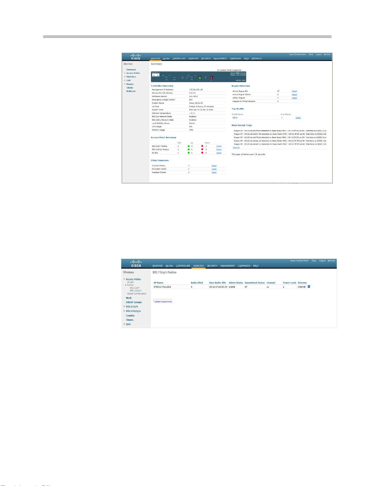
Summary, is installed on the controller. From the main menu, click
Monitor.
2. In the navigation pane, click Summary. The heading labeled Software
Version shows the current software version.
3. Download the appropriate software for your model of controller from
the Cisco website.
4. Set up a Trivial File Transfer Protocol (TFTP) server running on a PC
to download the file to the controller.
5. Connect to the controller via a Web browser.
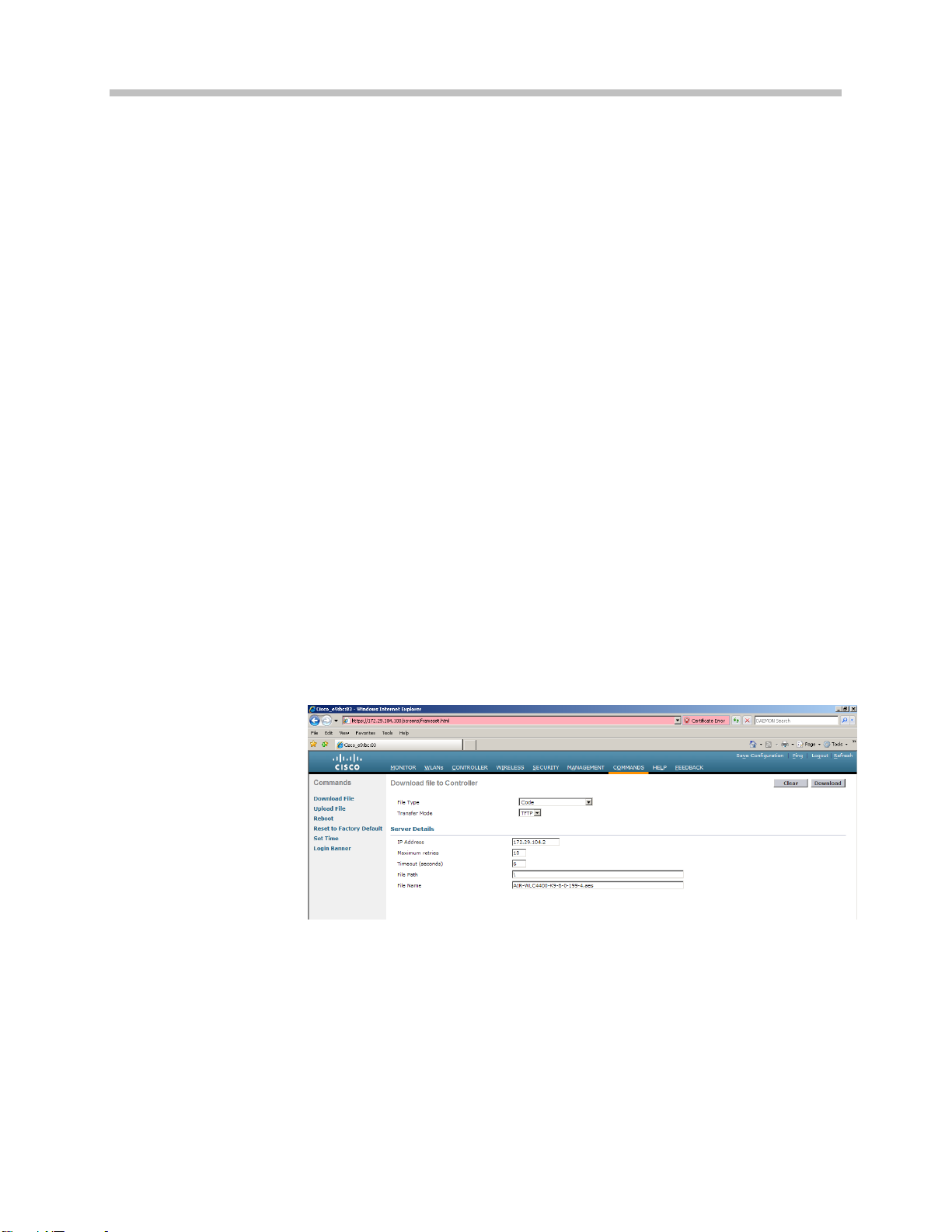
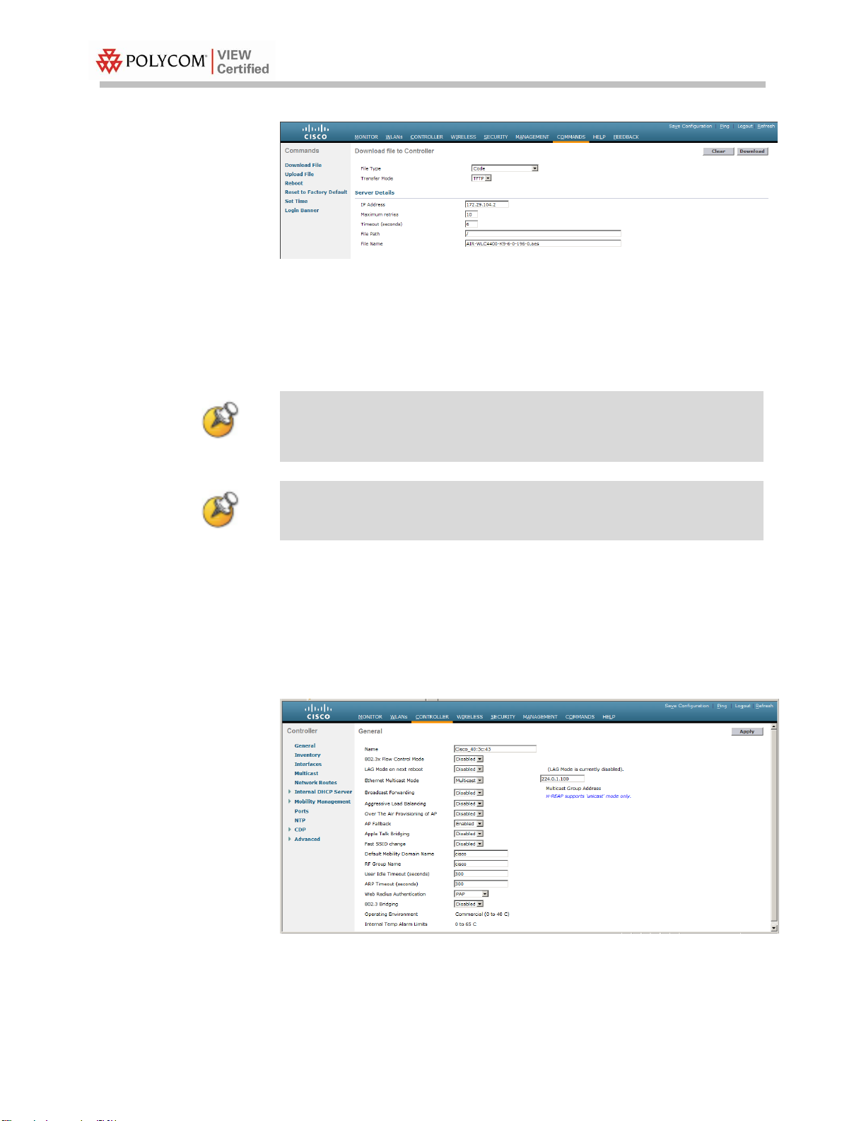
6. From the main menu, click Commands.
7. In the navigation pane, click Download File.
8. For File Type, select Code.
9. For TFTP Server, type in the IP Address of the TFTP server.
10. Add the File Path (this is the path in the TFTP server’s root directory
and not the system path where the TFTP server is located) and File
Name of the firmware file to download.
(Note the example simply uses the /designator for the root TFTP
directory.) Point the TFTP server to the code.
11. Allow a few minutes for the download to complete.
12. Reboot the Controller
Controller Setup
The initial setup of the controller is shown below.
PN: 1725-36192-001_H 9
Page 10

VIEW Certified Configuration Guide
10
The setup instructions outlined in this document are for the
configuration shown in the diagram only. Your configuration may
differ, and the appropriate adjustments must be made.
You can configure a DHCP server to run on a remote PC for a small
deployment. However, for large-scale deployments, an enterprisegrade DHCP server must be used.
1. From the main menu, click Controller.
2. Set the Ethernet Multicast Mode to Multicast and enter a multicast IP
address that is currently not being used on your network for the
Multicast Group Address.
3. Click the Apply button.
4. Click Save Configuration.
Connecting APs
1. From the main menu, click Controller.
As the APs are connected to the network, they should automatically
find the controller via the CAPWAP discovery algorithms. The
Dynamic Host Configuration Protocol (DHCP) server will assign each
AP an IP address.
The ap-manager and management interfaces’ configuration should
include the DHCP server you have configured. Alternately, you can
configure the DHCP server internally on the controller to hand out
leases to the connected clients. (Note: The WLC’s DHCP server does
not lease addresses to the AP.) The instructions for doing so are
included at the end of this document.
PN: 1725-36192-001_H
Page 11
All handsets operating on a given AP radio must have the same
QoS setting. All APs supporting the handsets must be configured to
enable the corresponding features.
Section 1: SVP Cisco Wireless LAN Controllers with 1100, 1130, 1140, 1200, 1230, 1240, 1250 APs
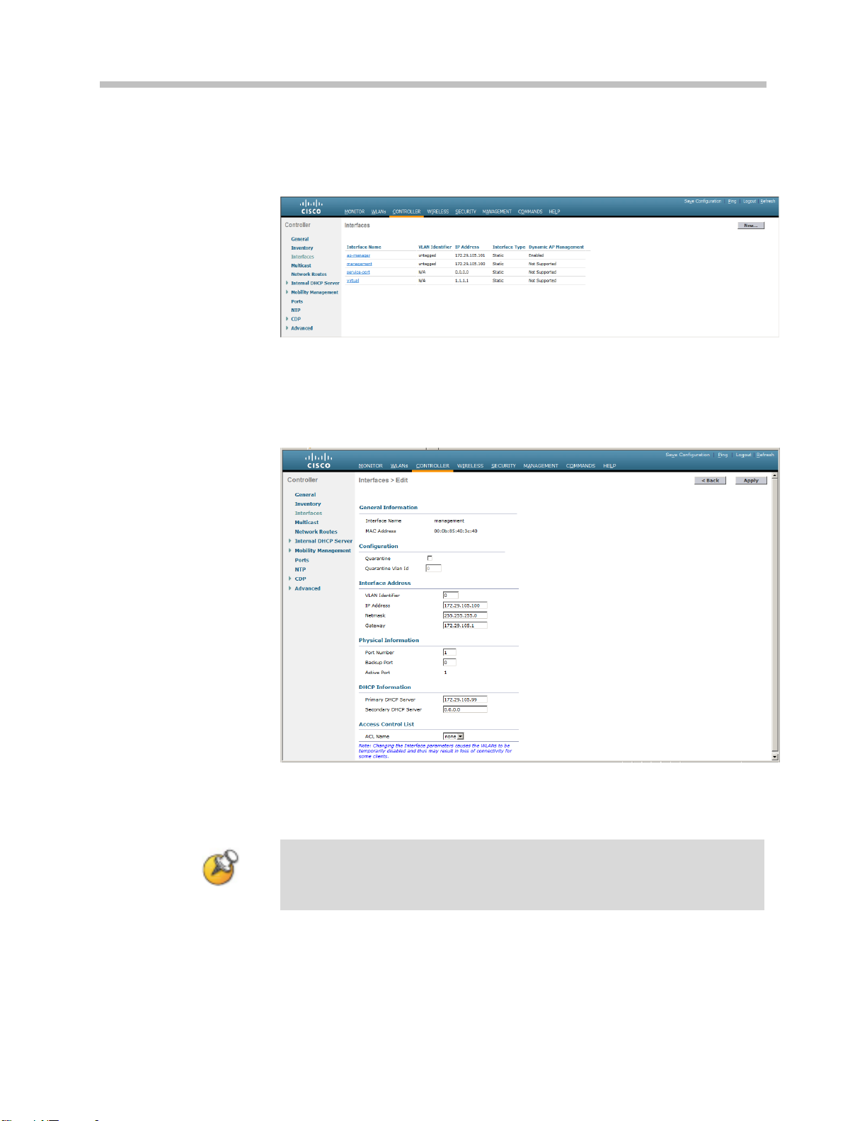
2. In the navigation pane, click Interfaces. Verify that the proper IP
addresses are assigned to the interfaces.
3. Under Interface Name click management.
4. Under DHCP Information, enter the IP address of the Primary DHCP
Server.
5. Repeat this step for the ap-manager interface.
6. Click the Apply button and save the changes.
AP Configuration
1. Power-on and connect the APs to the network. Wait a few minutes
for the APs to find the controller.
2. Verify the APs are associated to the WLC.
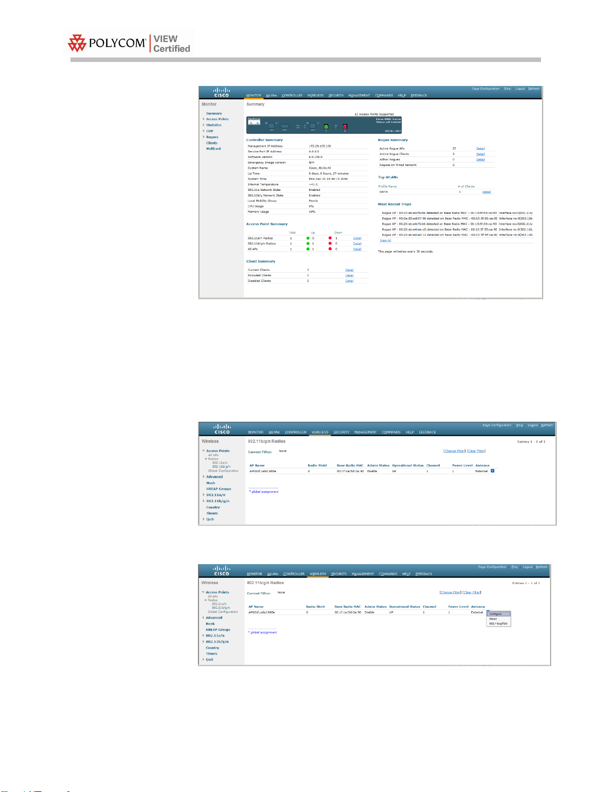
3. From the main menu, click Monitor.
PN: 1725-36192-001_H 11
Page 12
VIEW Certified Configuration Guide
12
Configuration for handsets running in 802.11b &
b/g mixed mode
1. From the main menu, click Wireless.
2. In the navigation pane, under Access Points click Radios, then select
802.11b/g/n. All the APs that are connected should be listed, showing
their Operational Status as UP.
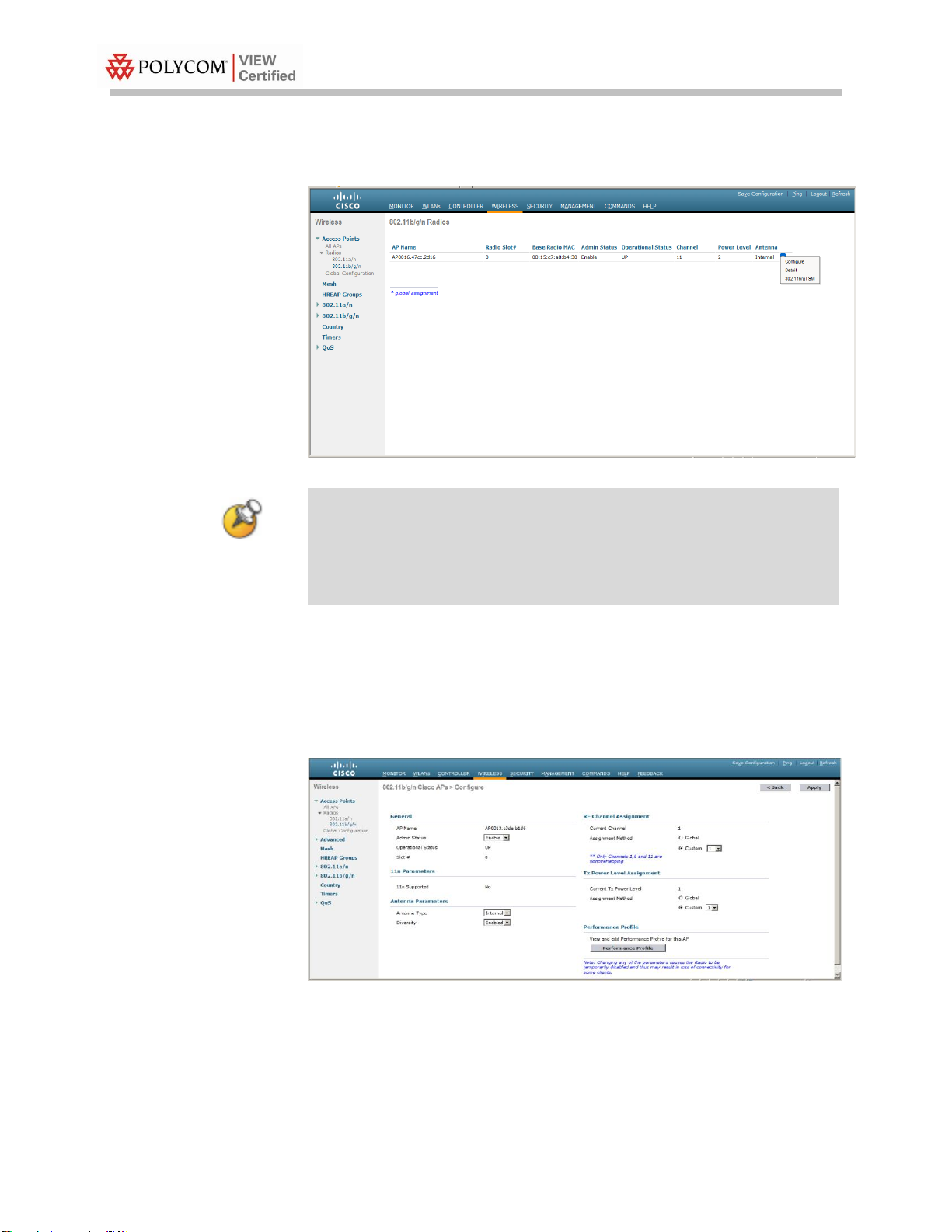
3. Select Configure from the drop-down list for the access point you
wish to change.
PN: 1725-36192-001_H
Page 13

Global settings for RF Channel Assignment and Tx Power Level
Assignment were not tested. For Custom Tx Power and RF Channel
settings please consult your facility’s RF site survey — optimized for
wireless voice traffic — to determine correct power and channel
settings for each AP using only channels 1, 6 and 11.
For setting up the Data Rates, please consult your facility’s RF site
survey, designed for voice traffic, to determine if you have sufficient
coverage to support all data rates. SpectraLink Wireless
Telephones require the following minimum dBm reading to support
the corresponding Mandatory data rate setting in the access point.
Section 1: SVP Cisco Wireless LAN Controllers with 1100, 1130, 1140, 1200, 1230, 1240, 1250 APs
4. Set Admin Status to Enable.
5. Configure any other settings that might be relevant to your
deployment as needed.
6. Click the Apply button to save all changes.
Screenshot for 1100, 1130, 1200, 1230 and 1240 series access points:
Screenshot for 1140 and 1250 series access points:
7. In the navigation pane under 802.11b/g/n, click Network.
8. Set 802.11b/g Network Status to Disable. The radio will be re- enabled
after setting radio parameters.
PN: 1725-36192-001_H 13
Page 14

VIEW Certified Configuration Guide
14
802.11
Radio Standard
Minimum Available
Signal Strength (RSSI)
Maximum
"Mandatory" Data Rate
802.11b
-70 dBm
1 Mb/s
-60 dBm
11 Mb/s
802.11g
-63 dBm
6 Mb/s
-47 dBm
54 Mb/s
802.11a
-60 dBm
6 Mb/s
-45 dBm
54 Mb/s
For additional details on RF deployment please see the Deploying
Enterprise-Grade Wi-Fi Telephony white paper and the Best
Practices Guide for Deploying SpectraLink 8020/8030 Wireless
Telephones.
9. Use the default Fragmentation Threshold (2346 bytes).
10. Set the Beacon Period to 100.
11. The handsets do not support dynamic power and will not utilize the
information element that is set when DTPC Support is enabled. The
handset power should be configured to match the highest transmit
power of the APs. Click the Apply button to save the settings.
12. In the navigation pane under 802.11b/g/n, select EDCA Parameters.
13. Select SpectraLink Voice Priority from the drop-down list.
14. Click the Apply button to save the settings.
15. In the navigation pane under 802.11b/g/n, select Network.
16. Enable 802.11b/g Network Status and 802.11g Support if SpectraLink
Wireless Telephones are configured for 802.11b & b/g mixed mode.
17. Click the Apply button to save the settings.
PN: 1725-36192-001_H
Page 15
Global settings for RF Channel Assignment and Tx Power Level
Assignment were not tested. For Custom Tx Power and RF Channel
settings please consult your facility’s RF site survey — optimized for
wireless voice traffic — to determine correct power and channel
settings for each AP using non-overlapping channels.
Section 1: SVP Cisco Wireless LAN Controllers with 1100, 1130, 1140, 1200, 1230, 1240, 1250 APs
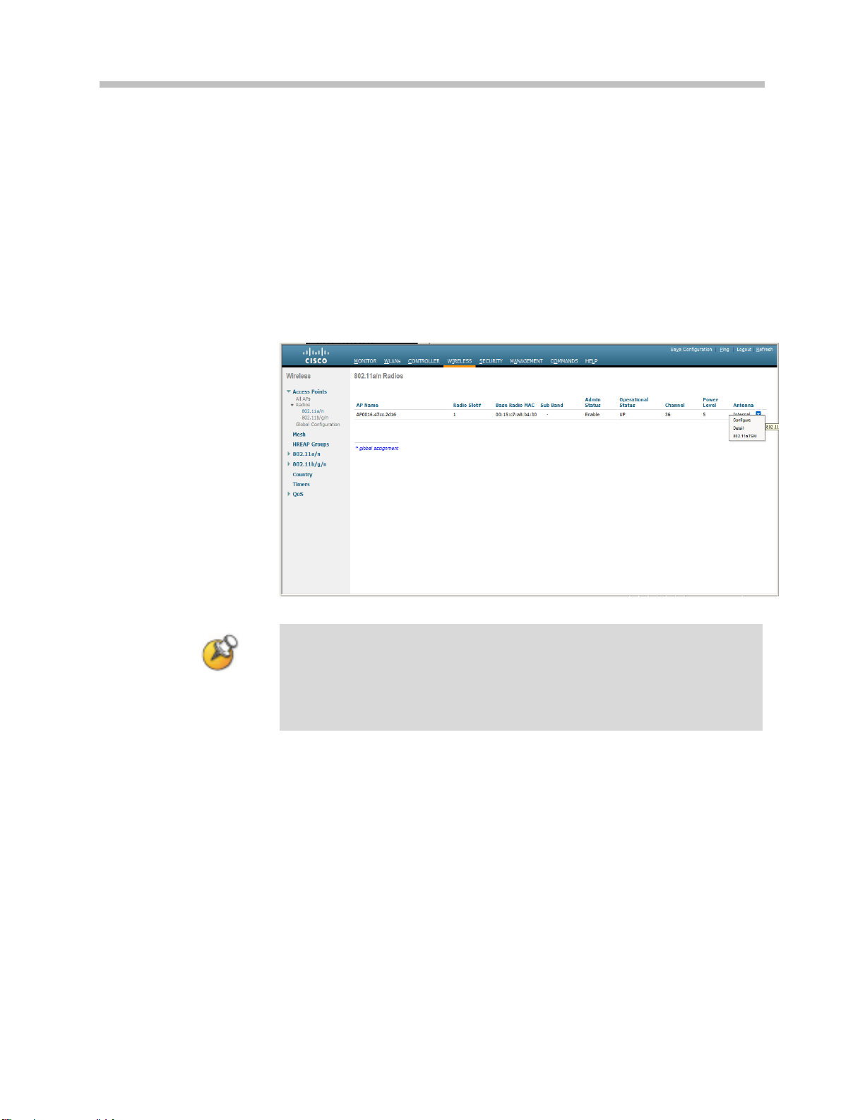
Configuration for handsets running in 802.11a
mode
1. From the main menu, click Wireless.
2. In the navigation pane, under Access Points click Radios, then select
802.11a /n. All the APs that are connected should be listed, showing
their Operational Status as UP.
3. Select Configure from the drop-down list for the access point you
wish to change.
4. Set Admin Status to Enable.
5. Configure any other settings that might be relevant to your
deployment as needed.
6. Click the Apply button to save all changes.
PN: 1725-36192-001_H 15
Page 16

VIEW Certified Configuration Guide
16
802.11
Radio Standard
Minimum Available
Signal Strength (RSSI)
Maximum
"Mandatory" Data Rate
802.11b
-70 dBm
1 Mb/s
-60 dBm
11 Mb/s
802.11g
-63 dBm
6 Mb/s
-47 dBm
54 Mb/s
802.11a
-60 dBm
6 Mb/s
-45 dBm
54 Mb/s
Screenshot for 1100, 1130, 1200, 1230 and 1240 series access points:
Screenshot for 1140 and 1250 series access points:
7. In the navigation pane under 802.11a/n, click Network.
8. Set 802.11a Network Status to Disable; the radio will be re-enabled
after setting radio parameters
9. For setting up the Data Rates, please consult your facility’s RF site
survey, designed for voice traffic, to determine if you have sufficient
coverage to support all data rates. The handset requires the following
minimum dBm reading to support the corresponding Mandatory data
rate setting in the access point.
PN: 1725-36192-001_H
Page 17

For additional details on RF deployment please see the Deploying
Enterprise-Grade Wi-Fi Telephony white paper and the Best
Practices Guide for Deploying SpectraLink 8020/8030 Wireless
Telephones.
Any WLAN using the network must be disabled before changing
EDCA Parameters.
Section 1: SVP Cisco Wireless LAN Controllers with 1100, 1130, 1140, 1200, 1230, 1240, 1250 APs
10. Use the default Fragmentation Threshold (2346 bytes).
11. Set the Beacon Period to 100.
12. SpectraLink Wireless Telephones do not support dynamic power and
will not utilize the information element that is set when DTPC support
is enabled. The handset power should be configured to match the
highest transmit power of the APs.
13. Click the Apply button to save the settings.
14. In the navigation pane under 802.11a/n, select EDCA Parameters.
15. Select SpectraLink Voice Priority from the drop-down list.
16. Click the Apply button to save the settings.
17. In the navigation pane under 802.11a /n, select Network.
18. For 802.11a Network Status, click the Enabled check box.
19. Click the Apply button to save the settings.
Setting up the SSID
Voice and data must be on separate SSIDs to prioritize voice traffic.
The voice SSID must be set to Platinum for Quality of Service and the
data SSID must be set to Silver for Quality of Service.
PN: 1725-36192-001_H 17
Page 18
VIEW Certified Configuration Guide
18
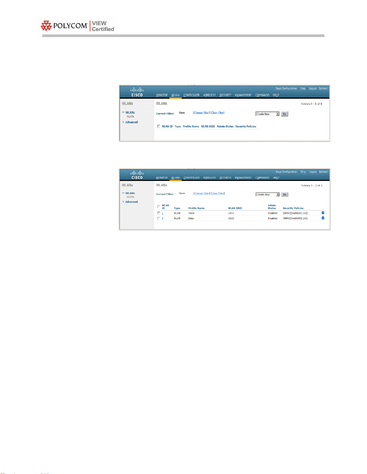
1. From the main menu, click WLANs.
2. In the WLANs screen, select Create New from the drop down list and
click Go.
3. Enter the Profile Name and SSID.
4. Click the Apply button.
5. Select the Profile Name for the voice SSID.
6. Under the General tab, verify the Radio Policy corresponds to the
SpectraLink Wireless Telephone configuration.
When Radio Policy is configured for 802.11b/g only, the handsets
should be configured for 802.11b & b/g mixed.
When Radio Policy is configured for 802.11a only, the handsets
should be configured for 802.11a.
When Radio Policy is configured for ALL. The handsets may be
configured for any of the settings without changing the Radio
Policy.
7. For Status, select the Enabled check box.
PN: 1725-36192-001_H
Page 19

Section 1: SVP Cisco Wireless LAN Controllers with 1100, 1130, 1140, 1200, 1230, 1240, 1250 APs
8. Under the QoS tab, set Quality of Service to Platinum. This is the
required setting for voice traffic.
9. Set WMM Policy to Disabled (Note: This is required for usage with
SpectraLink Wireless Telephones using SVP for QoS).
Under the Advanced tab, uncheck the Client Load Balancing & Client
Band Select boxes.
10. Under the Security tab. At Layer 2 Security select the desired security
policy from the drop-down list.
a. For WPA2-PSK, under WPA+WPA2 Parameters:
i. Select the WPA2-Policy check box.
ii. Select the AES check box for WPA2-Encryption.
iii. At Auth Key Mgmt select PSK from the drop-down list.
PN: 1725-36192-001_H 19
Page 20

VIEW Certified Configuration Guide
20
b. For WPA-PSK, under WPA+WPA2 Parameters:
i. Select the WPA-Policy check box.
ii. Select the TKIP check box for WPA Encryption.
iii. At Auth Key Mgmt select PSK from the drop-down list.
The PSK Format may be selected as ASCII or HEX for both
WPA-PSK and WPA2-PSK policies.
c. For WPA2-Enterprise (802.1X), under WPA+WPA2 Parameters:
i. Select the WPA2 Policy check box.
ii. Select the AES check box for WPA2 Encryption.
iii. At Auth Key Mgmt, select 802.1X+CCKM from the drop-
down list.
11. Under the Advanced tab
a Set the DTIM to 2 for the radio that corresponds to the
SpectraLink Wireless Telephone configuration.
b Ensure the Enable Session Timeout box is unchecked.
c Uncheck the Client Load Balancing and Client Band Select
boxes.
PN: 1725-36192-001_H
Page 21

Section 1: SVP Cisco Wireless LAN Controllers with 1100, 1130, 1140, 1200, 1230, 1240, 1250 APs
12. Click the Apply button to save all changes.
PN: 1725-36192-001_H 21
Page 22

Page 23

Cisco Wireless LAN Controllers with 1100, 1130, 1140, 1200, 1230, 1240, 1250 APs
SIP PBX
TFTP Server, DHCP Server
RADIUS Authentication Server
(for WPA2-Enterprise Security)
Wireless Data Client
SpectraLink 8000 series
Wireless Telephones
Cisco 4400 Series
WIRELESS LAN CONTROLLER
MODEL 4402 50 AP
CONSOLE
STATUS
ALARM
PS1
PS2
LINK
ACT
SERVICE
LINK
ACT
UTILITY 1 2
LINK
ACT
Cisco WLC
Cisco AP
Cisco AP
This configuration is not applicable to all customer environments.
Section 2: Configuration for Wi-Fi Standard
QoS or CCXv4 Operation
Network Topology
PN: 1725-36192-001_H 23
Page 24

VIEW Certified Configuration Guide
24
Configuring a New Controller Starting from Factory Defaults
1. Initial provisioning of the controller is done via the command line
interface (CLI). Connect a null modem serial cable between the
console port of the controller and the serial port of a PC.
2. Open a terminal program, such as Hyper Terminal, and configure the
port settings to 9600 baud, no parity, 8 data bits and 1 stop bit.
3. Power-on the controller. Status of the controller’s boot process will
appear as the controller is powering up. Once the controller is
running, it will prompt you to run the Startup Wizard.
4. The Startup Wizard provides for an easy means to perform initial
controller setup and provisioning. Refer to the Installation and Startup
Guide for the Cisco 4400 Series WLC, or other appropriate controller,
found at Cisco’s website. This document contains a detailed
explanation of using the Startup Wizard for the 4400:
http://www.cisco.com/en/US/docs/wireless/controller/4400/quic
k/guide/ctrlv32.html#wp34023
5. Once the controller has been configured via the Startup Wizard, the
remaining configuration can be configured through the switch-web
interface using a Web browser (Cisco recommends using MS IE 6.0+).
6. If necessary, the controller can be reset to factory defaults. To reset
the WLC to factory default, you must reboot, then type Recover-
config at the CLI. This only works before the first time a user logs in
via the console.
Connecting to the Controller Via a Browser
1. Connect to the WLC by pointing your internet browser to the URL:
https<IP_Addr> (where <IP_Addr> is the IP address of the
management interface of the WLC).
2. Click the Login prompt. The default User Name and Password is
admin.
3. Once logged in properly, a page similar to the one below displays.
PN: 1725-36192-001_H
Page 25

Section 2: WMM Cisco Wireless LAN Controllers with 1100, 1130, 1140, 1200, 1230, 1240, 1250 APs
Installing Software
1. Make sure that the correct version of software, listed in the Product
Summary, is installed on the controller. From the main menu, click
Monitor.
2. In the navigation pane, click Summary. The heading labeled Software
Version shows the current software version.
3. Download the appropriate software for your model of controller from
the Cisco website.
4. Set up a Trivial File Transfer Protocol (TFTP) server running on a PC
to download the file to the controller.
5. Connect to the controller via a Web browser.
6. From the main menu, click Commands.
7. In the navigation pane, click Download File.
8. For File Type, select Code.
9. For TFTP Server, type in the IP Address of the TFTP server.
10. Add the File Path (this is the path in the TFTP server’s root directory
and not the system path where the TFTP server is located) and File
Name of the firmware file to download.
(Note the example simply uses the /designator for the root TFTP
directory.) Point the TFTP server to the code.
11. Allow a few minutes for the download to complete.
PN: 1725-36192-001_H 25
Page 26
26
12. Reboot the Controller.
The setup instructions outlined in this document are for the
configuration shown in the diagram only. Your configuration may
differ, and the appropriate adjustments must be made.
It is not necessary to configure each AP individually. The WLC is
capable of provisioning the APs.
Controller Setup
VIEW Certified Configuration Guide
The initial setup of the controller is shown below.
1. From the main menu, click Controller.
2. Set the Ethernet Multicast Mode to Multicast and enter a multicast IP
address that is currently not being used on your network for the
Multicast Group Address.
3. Click the Apply button.
4. Click Save Configuration.
PN: 1725-36192-001_H
Page 27

You can configure a DHCP server to run on a remote PC for a small
deployment. However, for large-scale deployments, an enterprisegrade DHCP server must be used.
Section 2: WMM Cisco Wireless LAN Controllers with 1100, 1130, 1140, 1200, 1230, 1240, 1250 APs
Connecting APs
As the APs are connected to the network, they should automatically
find the controller via the CAPWAP discovery algorithms. The
Dynamic Host Configuration Protocol (DHCP) server will assign each
AP an IP address.
The ap-manager and management interfaces’ configuration should
include the DHCP server you have configured. Alternately, you can
configure the DHCP server internally on the controller to hand out
leases to the connected clients. (Note: The WLC’s DHCP server does
not lease addresses to the AP.) The instructions for doing so are
included at the end of this document.
1. From the main menu, click Controller.
2. In the navigation pane, click Interfaces. Verify that the proper IP
addresses are assigned to the interfaces.
3. Under Interface Name click management.
PN: 1725-36192-001_H 27
Page 28

VIEW Certified Configuration Guide
28
All handsets operating on a given AP radio must have the same
QoS setting. All APs supporting the handsets must be configured to
enable the corresponding features.
4. Under DHCP Information, enter the IP address of the Primary DHCP
Server.
5. Repeat this step for the ap-manager interface.
6. Click the Apply button and save the changes.
AP Configuration
1. Power-on and connect the APs to the network. Wait a few minutes
for the APs to find the controller.
2. Verify the APs are associated to the WLC.
3. From the main menu, click Monitor.
PN: 1725-36192-001_H
Page 29
Section 2: WMM Cisco Wireless LAN Controllers with 1100, 1130, 1140, 1200, 1230, 1240, 1250 APs
Configuration for handsets running in 802.11b &
b/g mixed mode
1. From the main menu, click Wireless.
2. In the navigation pane, under Access Points click Radios, then select
802.11b/g/n. All the APs that are connected should be listed, showing
their Operational Status as UP.
PN: 1725-36192-001_H 29
Page 30
VIEW Certified Configuration Guide
30
Global settings for RF Channel Assignment and Tx Power Level
Assignment were not tested. For Custom Tx Power and RF Channel
settings please consult your facility’s RF site survey — optimized for
wireless voice traffic — to determine correct power and channel
settings for each AP using only channels 1, 6 and 11.
3. Select Configure from the drop-down list for the access point you
wish to change.
4. Set Admin Status to Enable.
5. Configure any other settings that might be relevant to your
deployment as needed.
6. Click the Apply button to save all changes.
Screenshot for 1100, 1130, 1200, 1230 and 1240 series access points:
PN: 1725-36192-001_H
Page 31

For setting up the Data Rates, please consult your facility’s RF site
survey, designed for voice traffic, to determine if you have sufficient
coverage to support all data rates. SpectraLink Wireless
Telephones require the following minimum dBm reading to support
the corresponding Mandatory data rate setting in the access point.
802.11
Radio Standard
Minimum Available
Signal Strength (RSSI)
Maximum
"Mandatory" Data Rate
802.11b
-70 dBm
1 Mb/s
-60 dBm
11 Mb/s
802.11g
-63 dBm
6 Mb/s
-47 dBm
54 Mb/s
802.11a
-60 dBm
6 Mb/s
-45 dBm
54 Mb/s
For additional details on RF deployment please see the Deploying
Enterprise-Grade Wi-Fi Telephony white paper and the Best
Practices Guide for Deploying SpectraLink 8020/8030 Wireless
Telephones.
Section 2: WMM Cisco Wireless LAN Controllers with 1100, 1130, 1140, 1200, 1230, 1240, 1250 APs
Screenshot for 1140 and 1250 series access points:
7. In the navigation pane under 802.11b/g/n, click Network.
8. Set 802.11b/g Network Status to Disable. The radio will be re-enabled
after setting radio parameters.
9. Use the default Fragmentation Threshold (2346 bytes).
10. Set the Beacon Period to 100.
11. The handsets do not support dynamic power and will not utilize the
information element that is set when DTPC Support is enabled. The
PN: 1725-36192-001_H 31
Page 32

VIEW Certified Configuration Guide
32
Admission Control (ACM) must be enabled on both the Voice and
Video AC when the handset is configured for Admission Control
Mandatory.
Any WLAN using the network must be disabled before changing
Admission Control settings.
handset power should be configured to match the highest transmit
power of the APs. Click the Apply button to save the settings.
12. In the navigation pane under 802.11b/g/n, select EDCA Parameters.
13. Select WMM from the drop-down list.
14. Click Apply button to saved changes
15. In the navigation pane under 802.11b/g/n, select Voice
16. Select the Admission Control (ACM) checkbox. (This step is optional if
the handset is configured with Admission Control set to Optional,
this setting must match setting in Video)
17. In the navigation pane under 802.11b/g/n, select Video
18. Select the Admission Control (ACM) checkbox. (This step is optional if
the handset is configured with Admission Control set to Optional,
this setting must match setting in Voice)
PN: 1725-36192-001_H
Page 33

Any WLAN using the network must be disabled before changing
Admission Control settings.
Section 2: WMM Cisco Wireless LAN Controllers with 1100, 1130, 1140, 1200, 1230, 1240, 1250 APs
19. Click the Apply button to save the settings.
20. In the navigation pane under 802.11b/g/n, select Network.
21. Enable 802.11b/g Network Status and 802.11g Support if SpectraLink
Wireless Telephones are configured for 802.11b & b/g mixed mode.
22. Click the Apply button to save the settings.
PN: 1725-36192-001_H 33
Page 34

VIEW Certified Configuration Guide
34
Global settings for RF Channel Assignment and Tx Power Level
Assignment were not tested. For Custom Tx Power and RF Channel
settings please consult your facility’s RF site survey — optimized for
wireless voice traffic — to determine correct power and channel
settings for each AP using non-overlapping channels.
Configuration for handsets running in 802.11a
mode
1. From the main menu, click Wireless.
2. In the navigation pane, under Access Points click Radios, then select
802.11a /n. All the APs that are connected should be listed, showing
their Operational Status as UP.
3. Select Configure from the drop-down list for the access point you
wish to change.
4. Set Admin Status to Enable.
5. Configure any other settings that might be relevant to your
deployment as needed.
6. Click the Apply button to save all changes.
PN: 1725-36192-001_H
Page 35

802.11
Radio Standard
Minimum Available
Signal Strength (RSSI)
Maximum
"Mandatory" Data Rate
802.11b
-70 dBm
1 Mb/s
-60 dBm
11 Mb/s
802.11g
-63 dBm
6 Mb/s
-47 dBm
54 Mb/s
802.11a
-60 dBm
6 Mb/s
-45 dBm
54 Mb/s
Section 2: WMM Cisco Wireless LAN Controllers with 1100, 1130, 1140, 1200, 1230, 1240, 1250 APs
Screenshot for 1100, 1130, 1200, 1230 and 1240 series access points:
Screenshot for 1140 and 1250 series access points:
7. In the navigation pane under 802.11a/n, click Network.
8. Set 802.11a Network Status to Disable; the radio will be re-enabled
after setting radio parameters
9. For setting up the Data Rates, please consult your facility’s RF site
survey, designed for voice traffic, to determine if you have sufficient
coverage to support all data rates. The handset requires the following
minimum dBm reading to support the corresponding Mandatory data
rate setting in the access point.
PN: 1725-36192-001_H 35
Page 36

VIEW Certified Configuration Guide
36
For additional details on RF deployment please see the Deploying
Enterprise-Grade Wi-Fi Telephony white paper and the Best
Practices Guide for Deploying SpectraLink 8020/8030 Wireless
Telephones.
Admission Control (ACM) must be enabled on both the Voice and
Video AC when the handset is configured for Admission Control
Mandatory.
10. Use the default Fragmentation Threshold (2346 bytes).
11. Set the Beacon Period to 100.
12. SpectraLink Wireless Telephones do not support dynamic power and
will not utilize the information element that is set when DTPC support
is enabled. The handset power should be configured to match the
highest transmit power of the APs.
13. Click the Apply button to save the settings.
14. In the navigation pane under 802.11a/n, select EDCA Parameters.
15. Select WMM from the drop-down list.
16. Click Apply button to save setting.
PN: 1725-36192-001_H
Page 37

Section 2: WMM Cisco Wireless LAN Controllers with 1100, 1130, 1140, 1200, 1230, 1240, 1250 APs
17. In the navigation pane under 802.11a/n, select Voice
18. Select the Admission Control (ACM) checkbox. (This step is optional if
the handset is configured with Admission Control set to Optional,
this setting must match setting in Video)
19. In the navigation pane under 802.11a/n, select Video
20. Select the Admission Control (ACM) checkbox. (This step is optional if
the handset is configured with Admission Control set to Optional,
this setting must match setting in Voice)
21. Click the Apply button to save the settings.
22. In the navigation pane under 802.11a/n, select Network.
23. For 802.11a Network Status, click the Enabled check box.
24. Click the Apply button to save the settings.
Setting up the SSID
Voice and data must be on separate SSIDs to prioritize voice traffic.
The voice SSID must be set to Platinum for Quality of Service and the
data SSID must be set to Silver for Quality of Service.
PN: 1725-36192-001_H 37
Page 38

VIEW Certified Configuration Guide
38
1. From the main menu, click WLANs.
2. In the WLANs screen, select Create New from the drop down list and
click Go.
3. Enter the Profile Name and SSID.
4. Click the Apply button twice.
5. Select the Profile Name for the voice SSID.
6. Under the General tab, verify the Radio Policy corresponds to the
SpectraLink Wireless Telephone configuration.
When Radio Policy is configured for 802.11b/g only, the handsets
should be configured for 802.11b & b/g mixed.
When Radio Policy is configured for 802.11a only, the handsets
should be configured for 802.11a.
When Radio Policy is configured for All, the handsets may be
configured to any of the settings required.
7. For Status, select the Enabled check box.
PN: 1725-36192-001_H
Page 39

Section 2: WMM Cisco Wireless LAN Controllers with 1100, 1130, 1140, 1200, 1230, 1240, 1250 APs
8. Under the QoS tab, set Quality of Service to Platinum. This is the
required setting for voice traffic.
9. Set WMM Policy to Required.
10. Under the Security tab. At Layer 2 Security select the desired security
policy from the drop-down list.
a. For WPA2-PSK, under WPA+WPA2 Parameters:
i. Select the WPA2-Policy check box.
ii. Select the AES check box for WPA2-Encryption.
iii. At Auth Key Mgmt select PSK from the drop-down list.
b. For WPA-PSK, under WPA+WPA2 Parameters:
i. Select the WPA-Policy check box.
ii. Select the TKIP check box for WPA Encryption.
iii. At Auth Key Mgmt select PSK from the drop-down list.
PN: 1725-36192-001_H 39
Page 40

VIEW Certified Configuration Guide
40
The PSK Format may be selected as ASCII or HEX for both
WPA-PSK and WPA2-PSK policies.
c. For WPA2-Enterprise (802.1X), select WPA+WPA2 Parameters:
i. Select the WPA2 Policy check box.
ii. Select the AES check box for WPA2 Encryption.
iii. At Auth Key Mgmt, select 802.1X+CCKM from the drop-
down list.
11. Under the Advanced tab
a Set the DTIM to 2 for the radio that corresponds to the
SpectraLink Wireless phone configuration.
b Ensure the Enable Session Timeout box is unchecked.
c Uncheck the Client Load Balancing and Client Band Select
boxes.
12. Click the Apply button to save all changes.
PN: 1725-36192-001_H
 Loading...