

Page 1

User Guide
V2IU 4300T Converged
Network Appliance
October 2005
Page 2

Trademark Information
Polycom®, the Polycom logo design, [and others that appear in your document] are registered trademarks of Polycom,
Inc. [List other trademarks]™ are trademarks of Polycom, Inc. in the United States and various other countries. All other
trademarks are the property of their respective owners.
© 2005 Polycom, Inc. All rights reserved.
Polycom Inc.
4750 Willow Road
Pleasanton, CA 94588-2708
USA
No part of this document may be reproduced or transmitted in any form or by any means, electronic or mechanical, for
any purpose, without the express written permission of Polycom, Inc. Under the law, reproducing includes translating
into another language or format.
As between the parties, Polycom, Inc. retains title to, and ownership of, all proprietary rights with respect to the software
contained within its products. The software is protected by United States copyright laws and international treaty
provision. Therefore, you must treat the software like any other copyrighted material (e.g. a book or sound recording).
Every effort has been made to ensure that the information in this manual is accurate. Polycom, Inc. is not responsible
for printing or clerical errors. Information in this document is subject to change without notice.
Page 3

Contents
1 Introduction . . . . . . . . . . . . . . . . . . . . . . . . . . . . . . . . . . . 1–1
Contents
The 4300T Converged Network Appliance . . . . . . . . . . . . . . . . . . . . . . . . . 1–1
T1 Wide Area Network (WAN) Access Router . . . . . . . . . . . . . . . . . . 1–1
Security . . . . . . . . . . . . . . . . . . . . . . . . . . . . . . . . . . . . . . . . . . . . . . . . . . . . 1–1
VoIP . . . . . . . . . . . . . . . . . . . . . . . . . . . . . . . . . . . . . . . . . . . . . . . . . . . . . . 1–1
Quality of Service . . . . . . . . . . . . . . . . . . . . . . . . . . . . . . . . . . . . . . . . . . . 1–1
Call Quality Monitoring . . . . . . . . . . . . . . . . . . . . . . . . . . . . . . . . . . . . . 1–2
Future-proof Scalability . . . . . . . . . . . . . . . . . . . . . . . . . . . . . . . . . . . . . . 1–2
Feature Summary . . . . . . . . . . . . . . . . . . . . . . . . . . . . . . . . . . . . . . . . . . . . . . . 1–2
Front Panel LEDs . . . . . . . . . . . . . . . . . . . . . . . . . . . . . . . . . . . . . . . . . . . . . . . 1–3
Back Panel . . . . . . . . . . . . . . . . . . . . . . . . . . . . . . . . . . . . . . . . . . . . . . . . . . . . . 1–4
Power Connector . . . . . . . . . . . . . . . . . . . . . . . . . . . . . . . . . . . . . . . . . . . 1–4
Erase Button . . . . . . . . . . . . . . . . . . . . . . . . . . . . . . . . . . . . . . . . . . . . . . . 1–4
Management console port . . . . . . . . . . . . . . . . . . . . . . . . . . . . . . . . . . . . 1–4
T1/E1 WAN port . . . . . . . . . . . . . . . . . . . . . . . . . . . . . . . . . . . . . . . . . . . 1–5
Ethernet WAN port . . . . . . . . . . . . . . . . . . . . . . . . . . . . . . . . . . . . . . . . . 1–5
2 Getting Started . . . . . . . . . . . . . . . . . . . . . . . . . . . . . . . . .2–1
Physical Installation . . . . . . . . . . . . . . . . . . . . . . . . . . . . . . . . . . . . . . . . . . . . . 2–1
Desktop Installation . . . . . . . . . . . . . . . . . . . . . . . . . . . . . . . . . . . . . . . . . 2–1
Wall-Mount Installation . . . . . . . . . . . . . . . . . . . . . . . . . . . . . . . . . . . . . 2–1
Administration of the 4300T . . . . . . . . . . . . . . . . . . . . . . . . . . . . . . . . . . . . . 2–2
3 Configuring the 4300T . . . . . . . . . . . . . . . . . . . . . . . . . . . 3–1
Configuration Guide For IP Centrex Applications . . . . . . . . . . . . . . . . . . . 3–2
Configuration Outline . . . . . . . . . . . . . . . . . . . . . . . . . . . . . . . . . . . . . . . 3–3
Configuration Guide For Station Side IP PBX Applications . . . . . . . . . . . 3–5
Configuration Outline . . . . . . . . . . . . . . . . . . . . . . . . . . . . . . . . . . . . . . . 3–6
Configuration Guide For Trunk Side IP PBX Applications . . . . . . . . . . . . 3–7
Configuration Outline . . . . . . . . . . . . . . . . . . . . . . . . . . . . . . . . . . . . . . . 3–8
Configuration Guide For Hosted Video Applications . . . . . . . . . . . . . . . . 3–9
Configuration Guide For Enterprise Video Applications . . . . . . . . . . . . 3–11
1
Page 4

User Guide V2IU 4300T Converged Network Appliance
System Configuration . . . . . . . . . . . . . . . . . . . . . . . . . . . . . . . . . . . . . . . . . . 3–13
Configure the LAN Interface . . . . . . . . . . . . . . . . . . . . . . . . . . . . . . . . 3–13
Configuring VLANs in the 4300T . . . . . . . . . . . . . . . . . . . . . . . . . 3–14
Modify an Existing VLAN Configuration . . . . . . . . . . . . . . . . . . 3–16
Delete an Existing VLAN Configuration . . . . . . . . . . . . . . . . . . . 3–16
Assign the 4300T’s ALG to your Priority VLAN . . . . . . . . . . . . 3–17
Configure the WAN Interface . . . . . . . . . . . . . . . . . . . . . . . . . . . . . . . . 3–17
Protocol . . . . . . . . . . . . . . . . . . . . . . . . . . . . . . . . . . . . . . . . . . . . . . . 3–19
Frame Relay Mode and DLCI . . . . . . . . . . . . . . . . . . . . . . . . . . . . 3–19
Timing . . . . . . . . . . . . . . . . . . . . . . . . . . . . . . . . . . . . . . . . . . . . . . . . 3–20
Payload Loopback . . . . . . . . . . . . . . . . . . . . . . . . . . . . . . . . . . . . . . 3–20
Configure the DHCP Server . . . . . . . . . . . . . . . . . . . . . . . . . . . . . . . . . 3–20
Delete a DHCP IP Address . . . . . . . . . . . . . . . . . . . . . . . . . . . . . . 3–22
Disable The DHCP Server . . . . . . . . . . . . . . . . . . . . . . . . . . . . . . . 3–22
Configure Hostname, SNMP and Remote Logging . . . . . . . . . . . . . 3–23
Configure SNMP . . . . . . . . . . . . . . . . . . . . . . . . . . . . . . . . . . . . . . . 3–23
Disable SNMP . . . . . . . . . . . . . . . . . . . . . . . . . . . . . . . . . . . . . . . . . 3–24
Configure Remote System Logging . . . . . . . . . . . . . . . . . . . . . . . 3–24
Disable Remote System Logging . . . . . . . . . . . . . . . . . . . . . . . . . . 3–24
Configure a local Hostname . . . . . . . . . . . . . . . . . . . . . . . . . . . . . 3–25
Enable Mean Opinion Scoring (MOS) . . . . . . . . . . . . . . . . . . . . . 3–25
Set MOS Threshold . . . . . . . . . . . . . . . . . . . . . . . . . . . . . . . . . . . . . 3–25
Change the Administration Password . . . . . . . . . . . . . . . . . . . . . . . . 3–26
VoIP Configuration . . . . . . . . . . . . . . . . . . . . . . . . . . . . . . . . . . . . . . . . . . . . 3–26
Configure the VoIP ALG . . . . . . . . . . . . . . . . . . . . . . . . . . . . . . . . . . . . 3–27
Configure VoIP Subnet Routing . . . . . . . . . . . . . . . . . . . . . . . . . . . . . . 3–29
Enter a VoIP Subnet Route . . . . . . . . . . . . . . . . . . . . . . . . . . . . . . . 3–30
Delete a VoIP Subnet Route . . . . . . . . . . . . . . . . . . . . . . . . . . . . . . 3–30
Configure IP Phones, IADs or Softphones . . . . . . . . . . . . . . . . . . . . . 3–31
Data Networking Configuration . . . . . . . . . . . . . . . . . . . . . . . . . . . . . . . . . 3–32
NAT for Data Traffic . . . . . . . . . . . . . . . . . . . . . . . . . . . . . . . . . . . . . . . 3–32
Configure Dynamic NAT . . . . . . . . . . . . . . . . . . . . . . . . . . . . . . . . 3–33
Configure Static NAT . . . . . . . . . . . . . . . . . . . . . . . . . . . . . . . . . . . 3–33
Delete a Static NAT entry . . . . . . . . . . . . . . . . . . . . . . . . . . . . . . . . 3–34
Static IP routing . . . . . . . . . . . . . . . . . . . . . . . . . . . . . . . . . . . . . . . . . . . 3–34
Configure the static route . . . . . . . . . . . . . . . . . . . . . . . . . . . . . . . . 3–34
Delete the static route . . . . . . . . . . . . . . . . . . . . . . . . . . . . . . . . . . . 3–35
Firewall Configuration . . . . . . . . . . . . . . . . . . . . . . . . . . . . . . . . . . . . . 3–35
Enable or disable the firewall . . . . . . . . . . . . . . . . . . . . . . . . . . . . 3–36
Configure Basic settings . . . . . . . . . . . . . . . . . . . . . . . . . . . . . . . . . 3–36
Configure Advanced Settings . . . . . . . . . . . . . . . . . . . . . . . . . . . . 3–36
Remove Advanced Setting Entries . . . . . . . . . . . . . . . . . . . . . . . . 3–38
2
Page 5

Contents
Traffic Management Configuration . . . . . . . . . . . . . . . . . . . . . . . . . . . . . . 3–38
Enable Traffic Shaping . . . . . . . . . . . . . . . . . . . . . . . . . . . . . . . . . . . . . . 3–39
Optionally enable priority IP addresses . . . . . . . . . . . . . . . . . . . . . . . 3–40
Enable CAC . . . . . . . . . . . . . . . . . . . . . . . . . . . . . . . . . . . . . . . . . . . . . . . 3–40
Determining the maximum number of concurrent calls . . . . . . 3–41
Examples . . . . . . . . . . . . . . . . . . . . . . . . . . . . . . . . . . . . . . . . . . . . . . 3–41
A Closer Look at Traffic Management in the 4300T . . . . . . . . . . . . . 3–41
Classifying . . . . . . . . . . . . . . . . . . . . . . . . . . . . . . . . . . . . . . . . . . . . . . . . 3–42
Upstream Traffic Management . . . . . . . . . . . . . . . . . . . . . . . . . . . . . . . 3–42
Priority classes . . . . . . . . . . . . . . . . . . . . . . . . . . . . . . . . . . . . . . . . . 3–42
Scheduler . . . . . . . . . . . . . . . . . . . . . . . . . . . . . . . . . . . . . . . . . . . . . 3–42
Traffic shaper . . . . . . . . . . . . . . . . . . . . . . . . . . . . . . . . . . . . . . . . . . 3–42
Downstream Traffic Management . . . . . . . . . . . . . . . . . . . . . . . . . . . . 3–43
VoIP Survivability Configuration . . . . . . . . . . . . . . . . . . . . . . . . . . . . . . . . 3–44
Key benefits and features of VoIP survivability . . . . . . . . . . . . . . . . 3–44
How survivability works . . . . . . . . . . . . . . . . . . . . . . . . . . . . . . . . . . . . 3–45
Platform Support . . . . . . . . . . . . . . . . . . . . . . . . . . . . . . . . . . . . . . . . . . 3–46
2
V
IU Converged Network Appliances . . . . . . . . . . . . . . . . . . . . . 3–46
IP Phones . . . . . . . . . . . . . . . . . . . . . . . . . . . . . . . . . . . . . . . . . . . . . 3–46
PSTN Gateways . . . . . . . . . . . . . . . . . . . . . . . . . . . . . . . . . . . . . . . . 3–46
Configuring VoIP Survivability in V
2
IU Appliances . . . . . . . . . . . . 3–46
Step 1 – Enable VoIP Survivability . . . . . . . . . . . . . . . . . . . . . . . . 3–47
Step 2 – Configure call processing server reachability settings
(optional) . . . . . . . . . . . . . . . . . . . . . . . . . . . . . . . . . . . . . . . . . . . . . 3–47
Step 3 - Specify the number of digits to use for local dialing . . 3–48
Step 4 - Configure the IP address of the local LAN side PSTN
gateway (optional) . . . . . . . . . . . . . . . . . . . . . . . . . . . . . . . . . . . . . 3–49
Step 5 - Configure call processing server redundancy . . . . . . . 3–50
4 System Diagnostics . . . . . . . . . . . . . . . . . . . . . . . . . . . . . . 4–1
Viewing Software Version, Hardware Platform and the LAN MAC Address
4–1
Viewing the ALG registration code . . . . . . . . . . . . . . . . . . . . . . . . . . . . 4–2
Enter the Registration Code . . . . . . . . . . . . . . . . . . . . . . . . . . . . . . . 4–2
Viewing Networking Information . . . . . . . . . . . . . . . . . . . . . . . . . . . . . 4–2
Routing Information . . . . . . . . . . . . . . . . . . . . . . . . . . . . . . . . . . . . . 4–3
Link Status . . . . . . . . . . . . . . . . . . . . . . . . . . . . . . . . . . . . . . . . . . . . . 4–3
Interface Information . . . . . . . . . . . . . . . . . . . . . . . . . . . . . . . . . . . . 4–3
Viewing Advanced System Information . . . . . . . . . . . . . . . . . . . . . . . . 4–4
System Uptime . . . . . . . . . . . . . . . . . . . . . . . . . . . . . . . . . . . . . . . . . . 4–4
Process Information . . . . . . . . . . . . . . . . . . . . . . . . . . . . . . . . . . . . . 4–4
Memory Usage . . . . . . . . . . . . . . . . . . . . . . . . . . . . . . . . . . . . . . . . . . 4–4
System Logging Messages . . . . . . . . . . . . . . . . . . . . . . . . . . . . . . . . 4–5
3
Page 6

User Guide V2IU 4300T Converged Network Appliance
Passive Voice Call Monitoring . . . . . . . . . . . . . . . . . . . . . . . . . . . . . . . . 4–5
Accessing Troubleshooting Tools . . . . . . . . . . . . . . . . . . . . . . . . . . . . . 4–5
Verify Registered Voice and Video Devices . . . . . . . . . . . . . . . . . 4–6
Performing a Ping Test . . . . . . . . . . . . . . . . . . . . . . . . . . . . . . . . . . . 4–7
Performing a Traceroute Test . . . . . . . . . . . . . . . . . . . . . . . . . . . . . 4–7
Restarting Networking Processes . . . . . . . . . . . . . . . . . . . . . . . . . . 4–8
Rebooting the 4300T . . . . . . . . . . . . . . . . . . . . . . . . . . . . . . . . . . . . . 4–8
5 Saving and Restoring the 4300T Configuration . . . . . . . . . . 5–1
The ewn Command . . . . . . . . . . . . . . . . . . . . . . . . . . . . . . . . . . . . . . . . . 5–1
Create a Backup File and Save in Local Flash . . . . . . . . . . . . . . . . . . . 5–2
Copy a Backup File to a Remote TFTP Server . . . . . . . . . . . . . . . . . . . 5–2
Download a Backup File from a Remote TFTP Server . . . . . . . . . . . . 5–2
List the Available Backup Files . . . . . . . . . . . . . . . . . . . . . . . . . . . . . . . 5–2
Delete a Backup File . . . . . . . . . . . . . . . . . . . . . . . . . . . . . . . . . . . . . . . . . 5–3
Load a Backup File so that it Becomes the Running Configuration . 5–3
6 Upgrading the 4300T . . . . . . . . . . . . . . . . . . . . . . . . . . . . 6–1
Upgrade Procedure for Software Revision 1.3.11 or Later . . . . . . . . . . . . 6–1
Appendix . . . . . . . . . . . . . . . . . . . . . . . . . . . . . . .Appendix–1
Troubleshooting Tips . . . . . . . . . . . . . . . . . . . . . . . . . . . . . . . . . . . Appendix–1
Specifications . . . . . . . . . . . . . . . . . . . . . . . . . . . . . . . . . . . . . . . . . . Appendix–2
Appendix . . . . . . . . . . . . . . . . . . . . . . . . . . . . . . .Appendix–3
Neighboring Path Navigator Gatekeeper support . . . . . . . . . . . Appendix–3
Example 1 . . . . . . . . . . . . . . . . . . . . . . . . . . . . . . . . . . . . . . . . . . Appendix–3
V2IU A . . . . . . . . . . . . . . . . . . . . . . . . . . . . . . . . . . . . . . . . Appendix–5
Gatekeeper A . . . . . . . . . . . . . . . . . . . . . . . . . . . . . . . . . . . Appendix–5
Gatekeeper X . . . . . . . . . . . . . . . . . . . . . . . . . . . . . . . . . . . Appendix–5
Endpoints . . . . . . . . . . . . . . . . . . . . . . . . . . . . . . . . . . . . . . Appendix–6
Dialing plans . . . . . . . . . . . . . . . . . . . . . . . . . . . . . . . . . . . Appendix–6
Example 2 . . . . . . . . . . . . . . . . . . . . . . . . . . . . . . . . . . . . . . . . . . Appendix–7
V2IU A . . . . . . . . . . . . . . . . . . . . . . . . . . . . . . . . . . . . . . . . Appendix–8
Gatekeeper A . . . . . . . . . . . . . . . . . . . . . . . . . . . . . . . . . . . Appendix–8
Network Settings . . . . . . . . . . . . . . . . . . . . . . . . . . . . . . . . Appendix–9
VoIP ALG – H323 Settings . . . . . . . . . . . . . . . . . . . . . . . Appendix–10
V2IU B . . . . . . . . . . . . . . . . . . . . . . . . . . . . . . . . . . . . . . . . Appendix–12
Gatekeeper B . . . . . . . . . . . . . . . . . . . . . . . . . . . . . . . . . . Appendix–12
Network Settings . . . . . . . . . . . . . . . . . . . . . . . . . . . . . . . Appendix–13
VoIP ALG – H323 settings . . . . . . . . . . . . . . . . . . . . . . . Appendix–14
V2IU C . . . . . . . . . . . . . . . . . . . . . . . . . . . . . . . . . . . . . . . . Appendix–16
4
Page 7

Contents
Network Settings . . . . . . . . . . . . . . . . . . . . . . . . . . . . . . . Appendix–16
VoIP ALG – H323 Settings . . . . . . . . . . . . . . . . . . . . . . . Appendix–17
Endpoints . . . . . . . . . . . . . . . . . . . . . . . . . . . . . . . . . . . . . Appendix–19
Dialing plans . . . . . . . . . . . . . . . . . . . . . . . . . . . . . . . . . . Appendix–19
Path Navigator . . . . . . . . . . . . . . . . . . . . . . . . . . . . . . . . . . . . Appendix–20
Regulatory Notices . . . . . . . . . . . . . . . . . Regulatory Notices–1
END-USER LICENSE AGREEMENT FOR POLYCOM® SOFTWARE .
Regulatory Notices–1
FCC PART 15 NOTICE . . . . . . . . . . . . . . . . . . . . . Regulatory Notices–11
FCC PART 68 NOTICE TO USERS OF DIGITAL SERVICE Regulatory
Notices–11
INDUSTRY CANADA (IC) NOTICE . . . . . . . . . Regulatory Notices–12
5
Page 8

User Guide V2IU 4300T Converged Network Appliance
6
Page 9

Introduction
The 4300T Converged Network Appliance
The V2IU 4300T is an intelligent, all-in-one networking solution for enterprises
and service providers. It reduces costs by simplifying the deployment,
management and security of converged voice, video and data networks. The
4300T provides the following important functions for converged networks:
T1 Wide Area Network (WAN) Access Router
The 4300T provides an integrated T1 CSU/DSU for small and medium office
connectivity.
1
Security
VoIP
Quality of Service
A stateful packet inspection firewall is used in combination with a VoIP
application layer gateway to provide comprehensive “media-aware” security.
The 4300T also supports IPSec for secure site-to-site networking.
The 4300T resolves NAT/FW traversal problems for SIP, MGCP and H.323
tr affi c. It allo ws a s ingl e publ ic IP add ress t o be u sed f or mu ltip le VoI P cli ents .
VoIP survivability is also provided by the 4300T so that local SIP PSTN
gateways can be used for inbound/outbound calling during WAN link
failures.
The 4300T maximizes WAN link utilization while optimizing voice quality
using prioritization and shaping.
1 - 1
Page 10

User Guide V2IU 4300T Converged Network Appliance
Call Quality Monitoring
Passive call quality monitoring for each SIP or MGCP voice call includes
statistics needed to enforce SLAs and resolve networking problems that
negatively affect call quality.
Future-proof Scalability
The 4300T is a powerful, flexible platform that can be deployed initially as a
low-cost WAN access router and then licensed through software for more
advanced VoIP features and increased call performance. It is the ideal
platform for service providers offering DIA, hosted VoIP and managed
security services or enterprises migrating to converged voice and data
networks.
Feature Summary
• VoIP
— SIP, MGCP(for voice) and H.323 (for video) application layer gateway
enables a single public IP address to be used for multiple VoIP
endpoints
— VoIP survivability provides local call switching to PSTN gateways
during WAN link failures (SIP only)
• QoS
— Class based queuing/prioritization
— Diffserv marking and policing
— Traffic shaping
— VoIP call admission control prevents oversubscription of priority
queue
• Security
— Stateful packet inspection firewall
— VoIP aware firewall dynamically provisions and closes UDP ports
used for VoIP calls
— IPSec: 3DES, SHA-1
— NAT/PAT server hides enterprise LAN topology
• Passive Call Quality Monitoring
1 - 2
— Per call statistics include mean opinion score (average and minimum),
jitter, latency, packet loss and much more
— Alarms for poor MOS scores
Page 11
— Active call count indicators
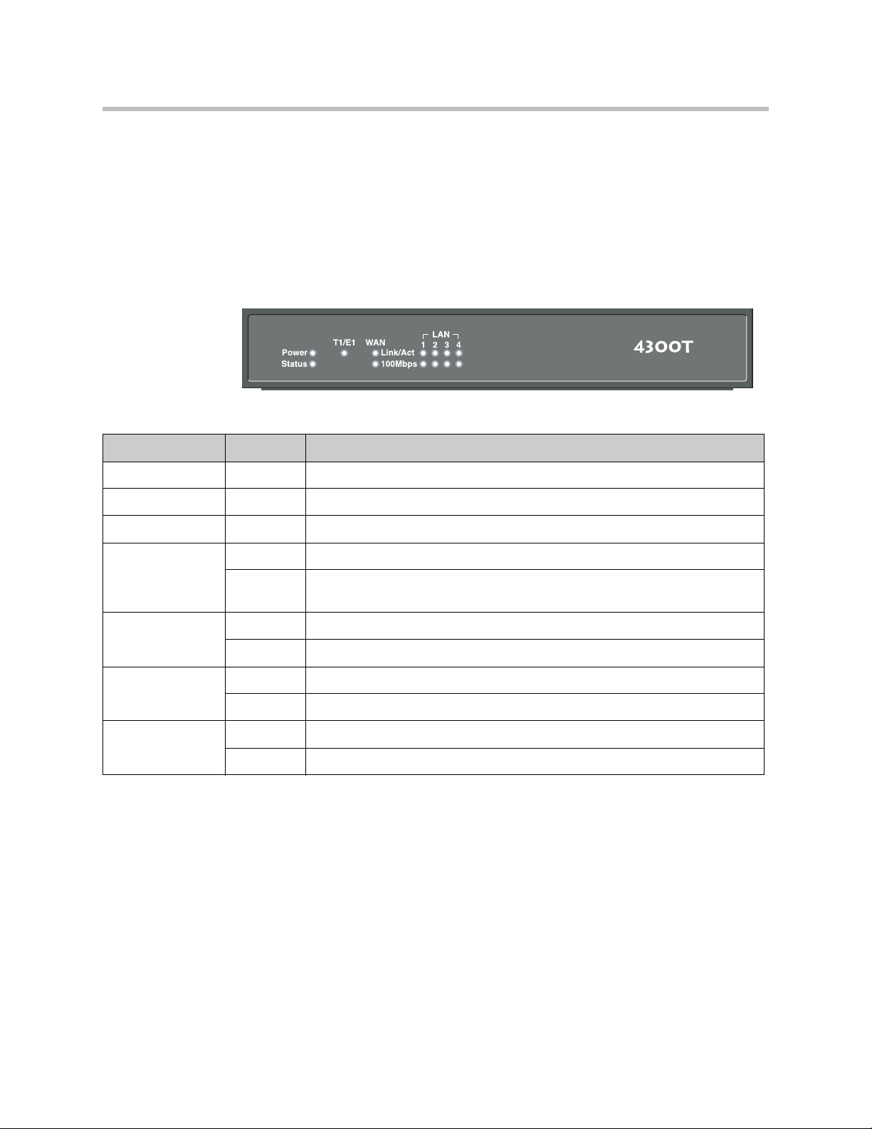
Front Panel LEDs
The LEDs display real-time information for key functions of the 4300T. They
are as follows:
LED Label Activity Description
Power Off Power switch off (or no power from wall)
Green Power is supplied to the unit
Introduction
EM001
Status Off Self-tests have failed. The unit has not booted.
Green Self-tests completed successfully
Flashing Indicates configuration is being written to permanent storage or an upgrade is
in progress
T1/E1 Off The T1 is in an alarm state and not synchronized
Green T1/E1 in-sync, no alarms
LAN Link/Act Flashing indicates activity. On indicates a connection
100Mbps On = 100Mbps link speed, Off = 10Mbps link speed
Ethernet WAN Link/Act Flashing indicates activity. On indicates a connection
100Mbps On = 100Mbps link speed, Off = 10Mbps link speed
1 - 3
Page 12

User Guide V2IU 4300T Converged Network Appliance
Back Panel
The back panel of the 4300T contains the following (left to right):
• Power connector
• Erase button
• Power connector
• 4 switched LAN Ethernet ports
• Management console port
• T1 WAN port (RJ-48 with built-in CSU/DSU)
EM002
• Ethernet WAN port
Power Connector
The 4300T comes with an AC power cord and power adapter for connecting to
this port. Little force is necessary when the plug is properly positioned.
Erase Button
To erase any custom configuration and restore the 4300T to its factory default
state depress the erase button once and press again before 2 seconds expires.
Warning
Using the Erase button as outlined above means any configuration made to the
4300T will be lost. Additionally the VoIP ALG registration code must be re-entered
in the 4300T as covered in Chapter 4: System Diagnostics, viewing the ALG
registration code. Erasing the configuration means that IP phones installed behind
the 4300T will not work and Internet connectivity or network access for PCs will be
down until the system is reconfigured.
Management console port
This port is used to establish a local console session with the 4300T using a
VT100 terminal or emulation program. The cable required is a
straight-through 8-wire cable. The serial port uses a baud rate of 9600, 8 data
bits, 1 stop bit and no parity.
1 - 4
Page 13

T1/E1 WAN port
Introduction
This port is used for debug or local diagnostic purposes only. Primary
configuration of the 4300T is performed from a web browser as covered in
Chapter 3.
The T1 WAN interface with the following features:
• Fully integrated CSU/DSU
• T1 support
• Fractional T1 support
• Layer 2 protocol support for: HDLC, Cisco HDLC (cHDLC), PPP, Frame
Relay
• On-board RJ-48 connector for easy direct connection
• T1/E1 framer and transceiver
— B8ZS/HDB3 zero suppression
— Response to Inband Loop codes
Ethernet WAN port
— Manual payload loop through the GUI
• External transmit clock input and receive clock output headers
• Timing: internal or external (loop times from the network)
• Provides long haul CSU or short haul DSU signaling
• Meets FCC part 68 protection requirements
The WAN port is used for connection to a data T1 line. The device at the far
end of the line is a router or other device expecting TCP/IP data. Individual
DS-0 channels on the T1 are not used to carry uncompressed voice.
The Ethernet 10/100 Mbps port on the 4300T can be used as a WAN interface
as an alternative to the T1 interface. This port is typically used when
connecting the 4300T to an existing T1/E1 WAN router, cable or xDSL
modem.
1 - 5
Page 14

User Guide V2IU 4300T Converged Network Appliance
1 - 6
Page 15

Getting Started
Physical Installation
The 4300T is designed for desktop, rack or wall-mount installation. Please
observe the following guidelines when installing the system:
• Never assume that the AC cord is disconnected from a power source.
Always check first.
• Always connect the AC power cord to a properly grounded AC outlet to
avoid damage to the system or injury.
Ensure that the physical location of the installation has adequate air circulation
and meets the minimum operating conditions as provided in the
environmental specifications for the system.
2
Warning
Secure the power supply using a fastener or nearby shelf so that it does not hang
from the power connector.
Desktop Installation
1. Remove the 4300T and accessories from the shipping container.
2. Place the 4300T on a flat, dry surface such as a desktop, shelf or tray.
3. Connect the power and network cables to the appropriate ports on the
Caution
To reduce the risk of fire, use only 26 AWG or larger wire (e.g. 24, 22, 20, etc.) to
connect the T1 port on your unit to an RJ-45 jack.
Wall-Mount Installation
The 4300T can be wall-mounted using the two mounting brackets on the
bottom of the appliance. We recommend using two round or pan head screws.
back of the system.
2 - 1
Page 16

User Guide V2IU 4300T Converged Network Appliance
Install two screws 4 14/16” horizontally apart on a wall or other vertical
surface. The screws should protrude from the wall so that you can fit the
appliance between the head of the screw and the wall.
1. If you install the screws in drywall use hollow wall anchors to ensure that
the unit does not pull from the wall due to prolonged strain from the
cable and power connectors.
2. Remove the 4300T and accessories from the shipping container.
3. Hang the 4300T on the wall.
4. Connect the power and network cables to the appropriate ports on the
back of the system.
Warning
Caution
Secure the power supply using a fastener or nearby shelf so that it does not hang
from the power connector.
To reduce the risk of fire, use only 26 AWG or larger wire (e.g. 24, 22, 20, etc.) to
connect the T1 port on your unit to an RJ-45 jack.
Administration of the 4300T
The 4300T is configured using a web browser such as Internet Explorer or
Netscape Navigator. The 4300T is shipped with a pre-configured IP address
for its LAN port of 192.168.1.1. To connect to the 4300T, do the following:
1. Connect a PC using an IP address of 192.168.1.2 and subnet mask of
255.255.255.0 to LAN port 4 of the 4300T.
2. Launch a web browser on the PC and enter the URL string: 192.168.1.1.
Press Return. The initial 4300T main configuration menu appears.
3. Select the Network link - enter the username root and the password
default to log into the system.
2 - 2
Page 17

Getting Started
Note
For secure management of your network, be sure to change the default userid and
password as described under Change the Administration Password.
4. Continue to configure the system using the information provided in
Chapter 3.
2 - 3
Page 18

User Guide V2IU 4300T Converged Network Appliance
2 - 4
Page 19

Configuring the 4300T
The 4300T is a flexible, easy to use converged network appliance that provides
many critical networking functions for IP based voice, video and data. It can
be installed in several different topologies:
• At the customer premise for IP Centrex and hosted video applications
• At the station side of enterprise IP PBXs
• At the trunk side of enterprise IP PBXs
• At the public/private IP address boundary for enterprise video
applications
Most users will follow the steps provided in the “Configuring The Systems
Settings” section of this manual to initially connect the 4300T into their IP
network. The remainder of the configuration can be different based on the
application, VoIP topology and presence of other networking equipment such
as firewalls or DHCP servers. In general, however, the steps used to configure
the 4300T are:
3
Step Task
1 System configuration
2 VoIP configuration
3 Data networking configuration
4 Firewall configuration
5 Traffic management configuration
6 VoIP survivability configuration
Some of the steps are optional depending on your particular application. We
have provided configuration guidelines below for each of the application
types supported by the 4300T.
3 - 1
Page 20
User Guide V2IU 4300T Converged Network Appliance
3
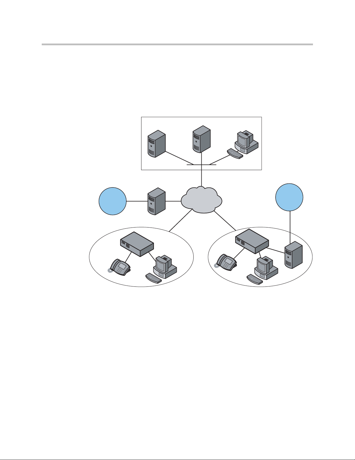
Configuration Guide For IP Centrex Applications
A typical 4300T installation for an IP Centrex application requires no external
router or firewall. The 4300T WAN port is connected directly to the T1/E1 line
and the LAN port(s) are connected directly to enterprise devices and/or
Ethernet switches.
VoIP Operations Center
Softswitch
Application Server
NMS
Gateway
PSTN
Enterprise Enterprise
T1/FT1 T1/FT1
4300T
T1
PSTN
4300T
Gateway
VoIP signaling is performed in the service provider network via a softswitch
and the 4300T acts as a proxy for the voice devices installed in the enterprise
LAN. In this configuration a single public IP address is used to proxy for all
of the IP phones and to route to multiple PC’s installed on the LAN.
The 4300T performs the following functions in this application:
• WAN/LAN IP routing.
EM00
3 - 2
• Traffic shaping and priority queuing to guarantee high quality voice
traffic. These mechanisms protect voice and data traffic from contending
for the same network resources to guarantee low latency and the highest
call quality possible for VoIP traffic. At the same time they ensure the best
utilization of WAN bandwidth by enabling data traffic to burst up to full
line rate in the absence of voice calls. Precedence is automatically given to
traffic coming from IP phones and other devices using the 4300T’s
Application Layer Gateway function.
Page 21

Configuring the 4300T
• NAT/PAT translation for IP phones and PC’s. This allows a single public
IP address to be used on the WAN link to represent all of the private IP
addresses assigned to the LAN IP phones and PC’s.
• Static NAT entries. This enables the customer to use a WAN public IP
address for data servers (web, mail, ftp, etc.) connected behind the 4300T.
These servers can then be configured with private IP addresses for
additional security.
• A “VoIP” aware firewall. A full Layer 7 gateway for voice traffic and a
stateful packet inspection firewall for data traffic.
• Call Admission Control (CAC). CAC uses a deterministic algorithm to
decide when there are insufficient network resources available to
adequately support new calls and then return the equivalent of a “fast
busy” to new call requests.
• DHCP server and TFTP relay. These features are used to simplify and
expedite the IP configuration of phones and PC’s. This also includes VoIP
signaling gateway information (MGCP, SIP, H.323 and SCCP).
• Call quality monitoring (using MOS, jitter, latency, packet loss and much
more) and test tools.
• VoIP survivability. Provides call switching to an LAN based PSTN
gateway during WAN outages.
Configuration Outline
Configure For IP Centrex
Task Subtask
System Configuration configure LAN/WAN interface Yes
set ethernet link rate Optional
enable the DHCP server Optional but recommended
configure SNMP Optional
VoIP Configuration enable the VoIP ALG Yes
configure a VoIP subnet route Optional
Data Networking Configuration dynamic NAT Optional but recommended
static NAT Optional
static IP routing Optional
Firewall Configuration enable the data firewall Yes
Application?
configure basic settings Optional
configure advanced settings Optional
3 - 3
Page 22

User Guide V2IU 4300T Converged Network Appliance
Traffic Management
enable traffic shaping Yes
Configuration
enable Call Admission Control Optional
VoIP Survivability enable VoIP survivability Yes
configure call processing server
Optional
reachability settings
specify the number of digits to use for
Optional
local dialing
configure the IP address of the local LAN
Optional
side PSTN gateway
configure call processing server
Optional
redundancy
3 - 4
Page 23
Configuring the 4300T
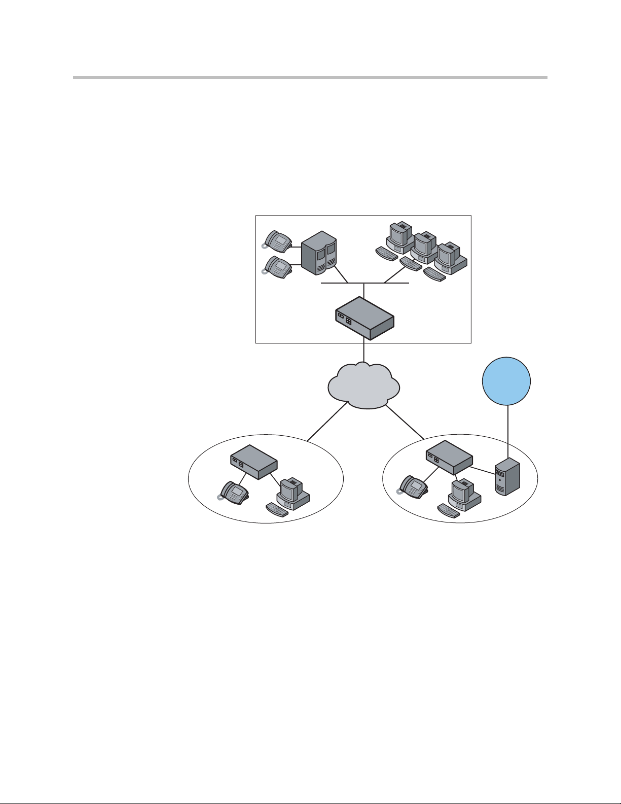
Configuration Guide For Station Side IP PBX Applications
Most private enterprise VoIP networks use an IP PBX at the corporate
headquarters location to provide voice switching between headquarters,
branch offices and the PSTN. The 4300T is used in these environments to
securely connect branch office employees to the IP PBX installed in the
corporate headquarters location.
Headquarters
IP PBX
4300T
T1
PSTN
Branch Office Branch Office
4300T
T1/FT1 T1/FT1
4300T
Gateway
EM004
The installation of an 4300T on the station side of an enterprise IP PBX is very
similar to the IP Centrex application above. The branch office is connected to
the corporate network using a private T1/E1 link connected directly to the
WAN port of the 4300T. The LAN port(s) of the 4300T are connected directly
to enterprise devices and/or Ethernet switches.
The IP PBX in the corporate headquarters location performs VoIP signaling
and the 4300T acts as a proxy for the voice devices installed at the branch
office. Please note that in the configuration the 4300T located at the
Headquarters location is acting as a WAN router only. The 4300Ts installed at
the brand offices perform the following functions in this application:
• WAN/LAN IP routing.
3 - 5
Page 24

User Guide V2IU 4300T Converged Network Appliance
• Traffic shaping and priority queuing to guarantee high quality voice
traffic. These mechanisms protect voice and data traffic from contending
for the same network resources to guarantee low latency and the highest
call quality possible for VoIP traffic. At the same time they ensure the best
utilization of WAN bandwidth by enabling data traffic to burst up to full
line rate in the absence of voice calls. Precedence is automatically given to
traffic coming from IP phones and other devices using the 4300T’s
Application Layer Gateway function.
• NAT/PAT translation for IP phones and PC’s. This allows a single IP
address to be used on the WAN link to represent all of the private IP
addresses assigned to the LAN IP phones and PC’s.
• A “VoIP” aware firewall. A full layer 7 gateway for voice traffic and a
stateful packet inspection firewall for data traffic.
• Call Admission Control (CAC). CAC uses a deterministic algorithm to
decide when there are insufficient network resources available to
adequately support new calls and then return the equivalent of a “fast
busy” to new call requests.
• DHCP server and TFTP relay. These features are used to simplify and
expedite the IP configuration of phones and PC’s. This also includes VoIP
signaling gateway information (MGCP, SIP, H.323 and SCCP).
• Call quality monitoring and test tools.
• VoIP survivability. Provides call switching to an LAN based PSTN
gateway during WAN outages.
Configuration Outline
Configure For Station
Side IP PBX
Task Subtask
System Configuration configure LAN/WAN interface Yes
set ethernet link rate Optional
enable the DHCP server Optional but
configure SNMP Optional
VoIP Configuration enable the VoIP ALG Yes
configure a VoIP subnet route Optional
Data Networking Configuration dynamic NAT Optional but
Application?
recommended
recommended
3 - 6
static NAT Optional
Page 25
static IP routing Optional
Firewall Configuration enable the data firewall Yes
configure basic settings Optional
configure advanced settings Optional
Configuring the 4300T
Traffic Management
enable traffic shaping Yes
Configuration
enable Call Admission Control Optional
VoIP Survivability enable VoIP survivability Yes
configure call processing server reachability
Optional
settings
specify the number of digits to use for local
Optional
dialing
configure the IP address of the local LAN side
Optional
PSTN gateway
configure call processing server redundancy Optional
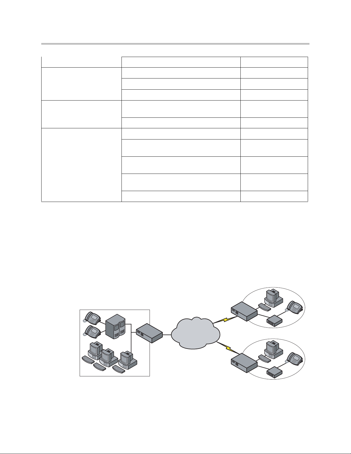
Configuration Guide For Trunk Side IP PBX Applications
Companies with existing IP-based WAN links for inter-office voice and data
communications can use the 4300T as a traffic shaper to meet the stringent
jitter, latency and packet loss requirements for toll quality voice. The 4300T is
deployed at the edge of the WAN in both headquarters and branch office
locations, as shown below.
Headquarters
IP PBX
4300T
Frame Relay
Or
IP Network
T1/E1
T1/E1
Branch Office
4300T
IP PBX
Branch Office
4300T
IP PBX
EM005
3 - 7
Page 26

User Guide V2IU 4300T Converged Network Appliance
The 4300T performs WAN/LAN IP routing and traffic management functions
in this application. In particular, it provides prioritization to ensure voice
packets are not delayed or dropped while allowing data traffic to use all
remaining bandwidth.
Configuration Outline
Task Subtask
System Configuration configure LAN/WAN interface Yes
set ethernet link rate Optional
enable the DHCP server Not required
configure SNMP Optional
VoIP Configuration enable the VoIP ALG Not required
configure a VoIP subnet route Not required
Configure For Trunk Side IP
PBX Application?
Data Networking
Configuration
Firewall Configuration enable the data firewall Not required
Traffic Management
Configuration
dynamic NAT Not required
static NAT Not required
static IP routing Not required
configure basic settings Not required
configure advanced settings Not required
enable traffic shaping Yes
enable Call Admission
Control
Not required
3 - 8
Page 27
Configuring the 4300T
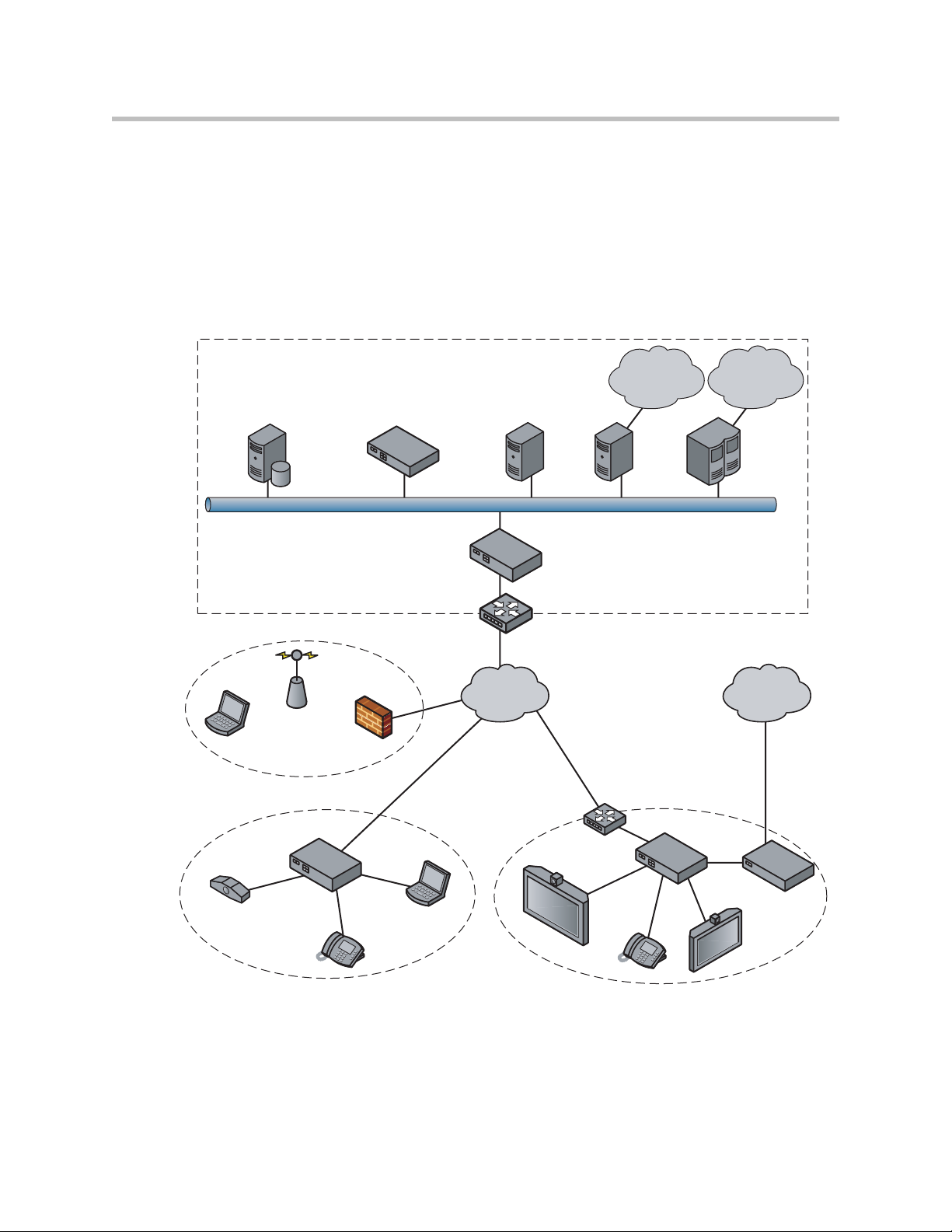
Configuration Guide For Hosted Video Applications
A typical 4300T installation for hosted video applications is depicted in the
diagram below. In this scenario, the 4300Ts are used to connect all of the video
endpoints to the Gatekeeper. The video endpoints should be configured to
point to the LAN address of the 4300T as the Gatekeeper and the 4300T will
proxy RAS and call setup messages to the Gatekeeper
Service Provider
H.323
Gatekeeper
SIP Voice
V500
NMS
Hotspot
NAT/Firewall
User
T-1/E-1 NxT-1/E-1
Company A Company B
4300T
IP
Phone
Laptop
Softswitch
Public IP
Network
Aggregation
Gateway MCU
5300-S
Aggregation Router
Router
H.323 Video
Endpoint
Phone
IP
PSTN
ISDN,
PSTN Network
PSTN
5300-E
Gateway
H.323 Video
Endpoint
EM008B
The 4300T is installed at the customer premises and is used as a demarcation
point for the video service by providing the following functions:
• WAN/LAN IP routing.
3 - 9
Page 28

User Guide V2IU 4300T Converged Network Appliance
• Traffic shaping and priority queuing to guarantee high quality video
traffic. These mechanisms protect video and data traffic from contending
for the same network resources to guarantee low latency and the highest
call quality possible for voice and video traffic. At the same time they
ensure the best utilization of WAN bandwidth by enabling data traffic to
burst up to full line rate in the absence of video calls. Precedence is
automatically given to traffic coming from video endpoints and other
devices using the 4300T’s Application Layer Gateway function.
• Video NAT/PAT translation for video endpoints and PC’s. This allows a
single IP address to be used on the WAN link to represent all of the private
IP addresses assigned to the LAN video endpoints and PC’s.
• A video aware firewall. A full layer 7 gateway for video traffic and a
stateful packet inspection firewall for data traffic
• Call Admission Control (CAC). CAC uses a deterministic algorithm to
decide when there are insufficient network resources available to
adequately support new video calls and then return the equivalent of a
“fast busy” to new call requests.
Task Subtask
Configure For Hosted
Video Applications?
System Configuration configure LAN/WAN interface Yes
set ethernet link rate Optional
enable the DHCP server Optional
configure SNMP Optional
VoIP Configuration enable the VoIP ALG Yes
configure a VoIP subnet route Optional
Data Networking Configuration dynamic NAT Optional but recommended
static NAT Optional
static IP routing Optional
Firewall Configuration enable the data firewall Yes
configure basic settings Optional
configure advanced settings Optional
Traffic Management
Configuration
enable traffic shaping Yes
enable Call Admission Control Optional
3 - 10
Page 29
Configuring the 4300T
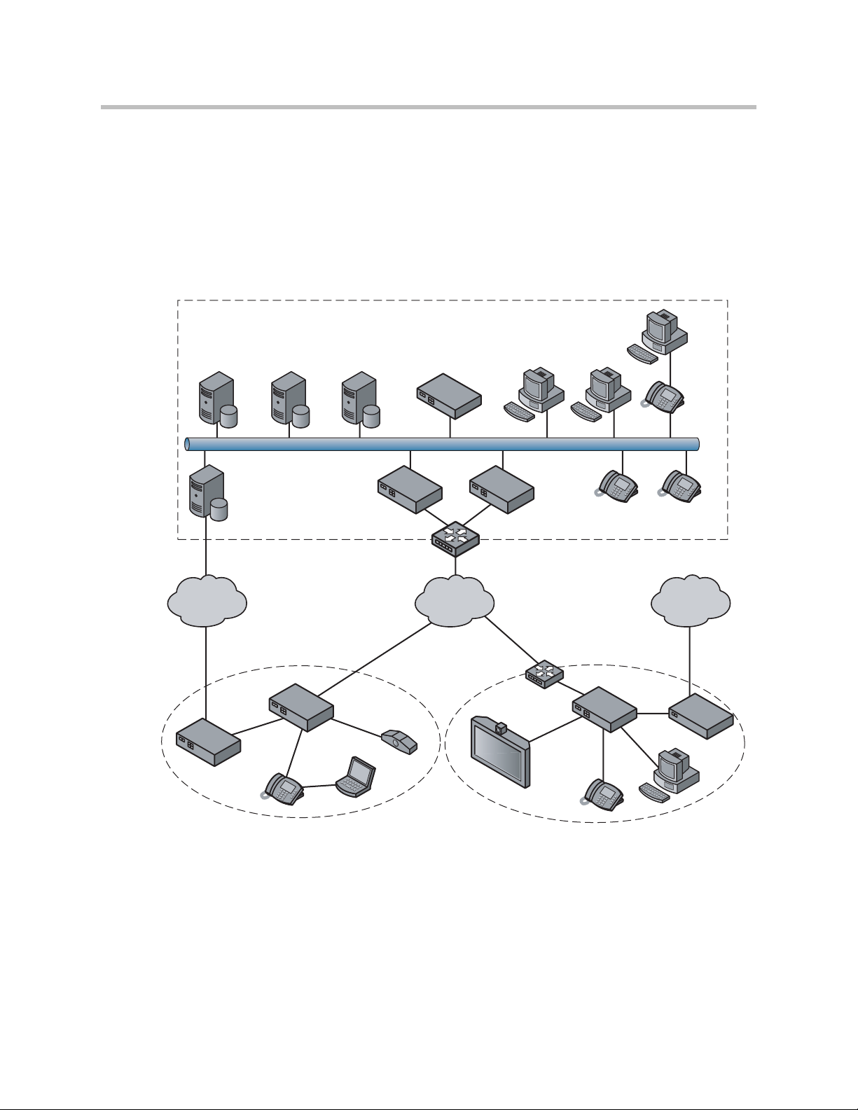
Configuration Guide For Enterprise Video Applications
A typical 4300T installation for enterprise video applications is depicted in the
diagram below. In this scenario, the 4300Ts are used to connect all of the video
endpoints to the Gatekeeper. The video endpoints should be configured to
point to the LAN address of the 4300T as the Gatekeeper and the 4300T will
proxy RAS and call setup messages to the Gatekeeper.
Headquarters
PC
H.323
Gatekeeper
Gateway
Gateway
Application
Server
PSTN
Branch Office Company B
Softswitch
5300-S 5300-E
T-1/E-1 NxT-1/E-1
4300T
H.323
NMS
Aggregation Router
IP
Network
Aggregation
Router
H.323
Endpoint
PC PC
IP Phone
IP PhoneIP Phone
PSTNPSTN
5300-E
Gateway
IP Phone
PC
EM009A
Laptop
IP Phone
The 4300T is installed at the private/public IP address boundary and provides
the following functions:
• WAN/LAN IP routing.
• Traffic shaping and priority queuing to guarantee high quality video
traffic. These mechanisms protect video and data traffic from contending
for the same network resources to guarantee low latency and the highest
3 - 11
Page 30

User Guide V2IU 4300T Converged Network Appliance
call quality possible for voice and video traffic. At the same time they
ensure the best utilization of WAN bandwidth by enabling data traffic to
burst up to full line rate in the absence of video calls. Precedence is
automatically given to traffic coming from video endpoints and other
devices using the 4300T’s Application Layer Gateway function.
• Video NAT/PAT translation for video endpoints and PC’s. This allows a
single IP address to be used on the WAN link to represent all of the private
IP addresses assigned to the LAN video endpoints and PC’s.
• A video aware firewall. A full layer 7 gateway for video traffic and a
stateful packet inspection firewall for data traffic
• Call Admission Control (CAC). CAC uses a deterministic algorithm to
decide when there are insufficient network resources available to
adequately support new video calls and then return the equivalent of a
“fast busy” to new call requests.
Task Subtask
System Configuration configure LAN/WAN interface Yes
Configure For Hosted
Video Applications?
set ethernet link rate Optional
enable the DHCP server Optional
configure SNMP Optional
VoIP Configuration enable the VoIP ALG Yes
configure a VoIP subnet route Optional
Data Networking Configuration dynamic NAT Optional but recommended
static NAT Optional
static IP routing Optional
Firewall Configuration enable the data firewall Yes
configure basic settings Optional
configure advanced settings Optional
Traffic Management
Configuration
enable traffic shaping Yes
enable Call Admission Control Optional
3 - 12
Page 31

System Configuration
This section explains how to configure the 4300T to function in your IP
network. You will configure the T1/E1 WAN interface, Ethernet interfaces,
network addresses, DNS settings, default gateway, SNMP settings and change
the administrative password.
1. Physically connect to the 4300T as described in Administration of the
4300T on page 2-2.
A browser-based configuration GUI should appear, as shown here.
Configuring the 4300T
2. Select the Network entry in the Configuration Menu.
Configure the LAN Interface
The 4300T provides an integrated 4 port 10/100 Mbps ethernet switch that can
be optionally configured to support 802.1q VLANs. Integrated VLAN support
simplifies the integration of the 4300T with existing VLAN-based networks.
The 4300T is able to receive 802.1q-tagged packets from a downstream VLAN
switch and appropriately route and process them per its firewall rules.
Packets received from the WAN are placed in the appropriate VLAN based on
IP address routing.
By default VLANs are not enabled and a single IP address is used for all 4
ethernet ports. The configuration of this address is as follows:
1. Enter the IP Address.
2. Enter the Subnet Mask (e.g. 255.255.255.0).
3 - 13
Page 32
User Guide V2IU 4300T Converged Network Appliance
3. Press Submit.
Configuring VLANs in the 4300T
As depicted in the diagram below, VLANs are used to connect the 4300T to an
Ethernet switch that has been configured to use VLANs.
VLANid 1/2
VLANid 1/3 VLANid 1/2/3
VLANid 1/2/3
802.1
VLAN
Switch
(VLANid 16)
4300T
P1
P2
P3
P4
WAN
EM006
Typically, all VoIP devices are placed in the same VLAN while data devices
are placed in a different VLAN. This is to ensure priority treatment of the VoIP
traffic on the LAN. Note that the 4300T does not require VLANs to prioritize
VoIP traffic; prioritization is determined by the VOS Application Layer
Gateway, regardless of VLAN. Some important notes about VLANs:
• A physical LAN port will operate in either 802.1 or 802.1q mode, not both
simultaneously
• The 4300T supports up to 16 VLANs
• A unique IP Subnet is assigned to each VLAN
3 - 14
• You can associate one or more VLANs to each LAN port operating in
802.1q mode
• Traffic within a VLAN is switched among all ports with membership
• Traffic between VLANs is routed by the 4300T
• The 4300T ALG can only be assigned to one VLAN id
— Only ALG traffic is prioritized over the WAN
— Other non-VoIP traffic in the same VLAN will not receive priority
treatment
• A DHCP server can be enabled/disabled per VLAN
• Cisco Discovery Protocol is not supported
Page 33

• 802.1p is not currently supported
1. Select the Network link.
2. Select Enable VLAN support.
3. Press Submit.
Configuring the 4300T
Caution
Be careful when changing a port from 802.1 to 802.1q mode. Any 802.1 devices
connected to that port (such as your management PC!) will loose access to the
4300T. Port 4 is only able to receive 802.1 frames, so a PC can always be
connected to this port if the configuration of the other ports is unknown.
4. Select System.
5. Select VLAN Configuration.
6. Adjust LAN Port Membership drop-down boxes to specify 802.1 or
802.1q mode, as desired. Press Modify.
If changing modes, the radio-buttons or checkboxes will change from one
style to the other.
7. Under Add and configure a new VLAN enter a new VLAN ID, the
4300T’s IP address within this VLAN, and the Network Mask. Press
Add.
A new VLAN entry will be added to the VLAN Configuration above.
8. Depending on the mode of a physical port, assign it to one or more
VLANs:
3 - 15
Page 34

User Guide V2IU 4300T Converged Network Appliance
— 802.1 mode: Assign the port to any ONE VLAN.
— 802.1q mode: Assign the port to any number of VLANs
Perform steps 1 through 6 above for each VLAN you wish to create.
Modify an Existing VLAN Configuration
1. Select the Network link.
2. Select VLAN Settings.
3. Change the desired settings.
4. Press the Modify to modify the VLAN. The Reset button will restore the
input area being modified to its previous value.
Delete an Existing VLAN Configuration
1. Select the Network link.
2. Select VLAN Settings.
3. Press the trash can icon next to the VLAN you wish to delete.
3 - 16
Page 35
Assign the 4300T’s ALG to your Priority VLAN
Configuring the 4300T
Once you have completed your VLAN configuration you must assign the
4300T ALG to the VLAN containing your VoIP phones.
1. Select the VoIP ALG from the main configuration menu.
2. Use the drop down menu to assign the ALG to the VLAN ID containing
your VoIP phones.
3. Press Submit.
Configure the WAN Interface
The 10/100 Ethernet WAN port is configured as follows:
1. Select ADSL-PPPoE if you want to connect to Internet using ADSL and
your ISP has given PPPoE username and password. Press Submit. You
will be prompted to enter username and password, enter these and press
Submit again.
2. Select DHCP if you want to get WAN side IP address using DHCP server
available in WAN side of the network. Press Submit.
3. Select Static IP address if you want to manually assign the IP address
configuration to the ethernet WAN interface.
4. Enter the IP Address.
5. Enter the Subnet Mask (e.g. 255.255.255.0).
3 - 17
Page 36

User Guide V2IU 4300T Converged Network Appliance
6. Enter the Default Gateway. This is usually the upstream router’s IP
address. Packets destined for IP networks not known to the 4300T are
forwarded to the default gateway for handling.
7. Enter the Primary DNS Server. The DNS server is used by the 4300T to
resolve domain names to IP addresses. The value entered into this field is
provided to IP devices that use the 4300T as a DHCP server. The 4300T
VoIP ALG also uses it if domain names are used instead of IP addresses
to identify signaling and/or TFTP servers (see the section entitled
“Configuring the VoIP ALG” for more details).
8. Enter the Secondary DNS Server. This server will be used in the event
that the primary DNS server is not reachable.
9. Press Submit.
To enable the T1 interface:
1. Select Network.
2. Select the T1 radio button.
3. Select Submit.
To configure the T1 parameters:
1. Select Network.
2. Select the T1 link next to the radio button to proceed to the T1
Configuration page.
The T1 Configuration menu will display, as shown here.
3 - 18
The 4300T supports a wide range of T1/E1 Layer 2 configuration parameters.
The specific values you will need must be supplied by the WAN provider.
Each of the 4300T’s configurable parameters are described below.
Page 37

Configuring the 4300T
Protocol
Display and set the T1 Layer 2 protocol. Supported protocols are:
• HDLC
• Cisco HDLC
• PPP
• ANSI (Frame Relay)
• CCITT (Frame Relay)
1. Select the desired T1 protocol.
2. Press Submit.
Frame Relay Mode and DLCI
When the Protocol is one of ANSI or CCITT, then additional Frame Relay
configuration parameters are required.
The Frame Relay Mode is usually set to DTE for the customer premises.
The Frame Relay DLCI is set by the WAN provider and identifies the far-end
device across the Frame Relay network. This DLCI can also be used to carry
voice traffic only by enabling the Secondary DLCI for data.
Most installations will use a single DLCI for both voice and data traffic.
However, in instances where the network will provide a different quality of
service based on DLCI number it is desirable to place all voice traffic on one
DLCI and then configure a second DLCI for data. In this case, the Secondary
DLCI is configured as follows:
1. Select Network.
2. Select the T1 link next to the radio button to proceed to the T1
configuration page.
3. Select Enable in the Frame Relay Secondary Settings section of the page.
4. Enter the Secondary DLCI, IP Address, Network Mask and Gateway for
the data traffic using the Secondary DLCI.
3 - 19
Page 38

User Guide V2IU 4300T Converged Network Appliance
Timing
Display and set the clock timing source for the T1/E1 interface. The timing can
be either derived from the network (External) or provided to the T1 interface
by the V
2
IU (Internal). With a carrier-provided T1, the timing is usually
derived from the network (External, the default setting).
Warning
Mismatched timing modes can result in WAN connectivity but with intermittent data
loss.
Payload Loopback
Display and set the loopback setting. During T1 line testing the local interface
can be set to Loopback to allow the network provider to verify connectivity
and line quality. For normal operation the setting should always be No
Loopback (the default setting).
Configure the DHCP Server
3 - 20
The 4300T can act as a DHCP server granting IP addresses to PCs,
workstations, servers or voice devices (IP phones, IADs or softphones)
connected to its LAN interfaces. DHCP is a protocol that enables IP devices to
obtain temporary or permanent IP addresses (out of a pool) from centrally
administered servers.
The user can configure blocks of IP addresses, a default gateway, DNS servers,
NTP server address, Time offset from NTP value, WINS address and
TFTP/FTP server name that can be served to the requesting IP devices.
Page 39

Configuring the 4300T
In addition the 4300T will provide its LAN IP address in DHCP user options
150 and 151 for use by IP phones. Some IP phones use these values for
configuration of their TFTP server and MGCP control server addresses.
Note
The DHCP server in the 4300T should not be used if a DHCP server already exists
in the same subnet as the 4300T. Also, it is recommended that you assign static IP
addresses for common-access devices such as network printers or fax machines.
You can also enable or disable the 4300T DHCP server on a per VLAN basis.
1. Select DHCP Server.
2. If you are using VLANs select the desired VLAN ID from the drop down
menu.
3. The default value for the DHCP server is disabled. Click the top
checkbox to enable or disable the internal DHCP server (default is
disabled). If you are using VLANs select the desired VLAN ID.
4. Enter the Lease Duration.
The lease duration is the amount of time in days that an IP device may use
an assigned IP address before requesting that it be renewed. The default
value is 7 days and the valid range of input is 1 to 30 days.
5. Enter the Subnet Mask.
This is the subnet mask that will be sent via DHCP to the requesting IP
devices.
6. Enter the DHCP IP Addresses.
This is the pool of IP addresses that will be provided to the requesting IP
devices. You can enter both individual IP addresses or a range of
addresses using the following format:
Note
192.168.1.2 (single address)
192.168.1.4-10 (address range 192.168.1.4 through 192.168.1.10)
The range format can only be used for class C addresses (those with a subnet
mask of 255.255.255.0).
7. Enter the Time Offset (DHCP user option 2).
8. Set the time offset in hours from UTC for your local location. This value
is optional; if supplied, it will be delivered to clients.
9. Enter the NTP Server Address (DHCP user option 42).
This is the IP address of a Network Time Server. This value is optional; if
supplied, it will be delivered to clients.
10. Enter the WINS Address.
3 - 21
Page 40

User Guide V2IU 4300T Converged Network Appliance
Note
If you are not using WINS leave this field blank.
The Windows Internal Naming Service (WINS) is a service that keeps a
database of computer name-to-IP address mappings so that computer
names used in Windows environments can be mapped to IP addresses.
The WINS Address is the IP address of the WINS server in your network.
This value will be delivered to clients.
1. Enter the TFTP/FTP Server Name (DHCP user option 66).
Some IP phones use this setting to locate the TFTP or FTP servers which
contain the phone software image used during boot. By default this
option is the same as the TFTP server on the VoIP ALG page.
2. Primary and Secondary DNS
The primary and secondary DNS values come from those set under the
WAN interface configuration, see Configure the WAN interface. These
values will be delivered to clients.
3. Default Gateway
The default gateway is automatically set to the 4300T’s LAN address, see
Configure the LAN interface. This value will be delivered to clients.
4. Press Submit.
Delete a DHCP IP Address
1. Select DHCP Server.
2. To delete an IP address or a range of IP addresses highlight an entry or
range of entries in the DHCP IP Addresses list and press the Delete key
on your keyboard.
3. Press Submit.
Disable The DHCP Server
1. Select DHCP Server.
2. Uncheck the Enable DHCP Server checkbox.
3 - 22
Page 41
3. Press Submit.
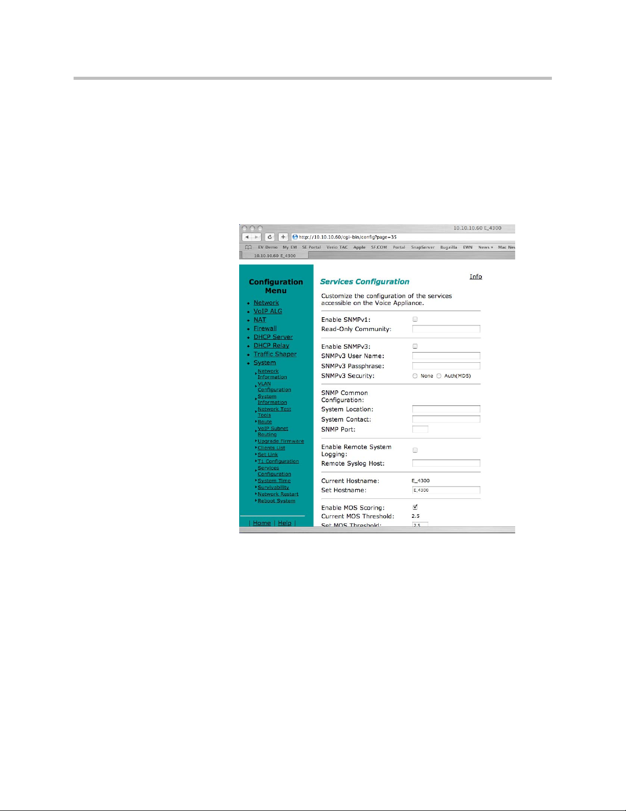
Configure Hostname, SNMP and Remote Logging
The 4300T can be managed remotely by an SNMP network management
system such as HP Openview. The 4300T supports SNMPv1 or SNMPv3 and
MIB-II (RFC1213). All MIB-II variables are read only. The MIB variables
sysContact and sysLocation are set by the web GUI.
Configuring the 4300T
Messages generated by the 4300T can be sent to a remote log server.
The configuration screen is reached through the Configuration Menu:
1. Select System.
2. Select System Overview.
3. Select Services Configuration.
Configure SNMP
3 - 23
Page 42

User Guide V2IU 4300T Converged Network Appliance
1. Select the Enable SNMP v1 or v3 checkbox. If using SNMPv1 enter the
Read-Only Community. If using SNMPv3 enter the User Name,
Passphrase and Security method.
2. Enter the System Location.
This is a comment string that can be used to indicate the physical location
of the 4300T. By default, no value is set.
3. Enter the System Contact.
This is the administrative contact information for the 4300T. By default,
no value is set.
4. Enter the SNMP Port.
This is the port that the 4300T uses for SNMP communications with the
network management system. The default is 161.
5. Press Submit.
Disable SNMP
1. Select System.
2. Select System Overview.
3. Select Services Configuration.
4. Uncheck the Enable SNMP checkbox.
5. Press Submit.
Configure Remote System Logging
The 4300T can be configured to log system messages to an external syslog
server.
1. Select the Enable Remote System Logging checkbox.
2. Enter the IP address of the Remote Syslog Host.
By default messages are sent to the remote host on port 514. This port can
be changed by using the syntax ADDRESS:PORT.
3. Press Submit.
Disable Remote System Logging
1. Select System.
3 - 24
2. Select System Overview.
3. Select Services Configuration.
Page 43

Configuring the 4300T
4. Uncheck the Enable Remote System Logging checkbox.
5. Press Submit.
Configure a local Hostname
A locally configured hostname is useful for remote management. This name
can appear as the identifier string for the 4300T on a system management
console.
>>
Enter a host name in the field provided.
Enable Mean Opinion Scoring (MOS)
The 4300T produces useful statistics on a per call basis that can be written to
syslog. These include MOS, jitter, latency, packet loss and much more.
1. Select System.
2. Select System Overview.
3. Select Services Configuration.
4. Select Enable MOS.
Set MOS Threshold
You can define a minimum MOS value in the 4300T such that a message will
be sent to syslog when the measured MOS value drops below the minimum.
This is useful when for monitoring a particular location for call quality
problems and enables pro-active resolution of problems that negatively affect
call quality.
1. Select System.
2. Select System Overview.
3. Select Services Configuration.
4. Enter the minimum MOS threshold in the Set MOS threshold field.
5. Press Submit
3 - 25
Page 44

User Guide V2IU 4300T Converged Network Appliance
Change the Administration Password
We strongly recommend that you change the default password for the root
administrative account using the following steps:
Note
The new password must be between 6 and 20 characters in length. Any
combination of alpha and numeric characters is accepted.
1. Enter the password you chose in step C again in the Confirm Password to
2. Press Submit.
VoIP Configuration
The 4300T provides a VoIP application layer gateway (ALG) for the SIP,
MGCP, and H.323 protocols. The ALG proxies the connection between the
VoIP softswitch, IP PBX or gatekeeper and voice and video devices such as IP
phones, IADs or softphones. By acting as a proxy the 4300T is able to provide
several important functions for IP based voice and video:
• Provide NAT/PAT services for voice and video traffic. NAT/PAT for
ensure that there were no mistakes in the initial entry.
VoIP enables you to use a single public IP address on the WAN interface
of the 4300T to represent multiple private IP addresses assigned to voice
or video devices on the LAN. The NAT function maps both IP address
and IP port number between the public and private addresses so that all
signaling and VoIP media packets are translated. A single public IP
address can support up to 253 voice and video devices.
3 - 26
• Provide security services for voice and video traffic.
— NAT/PAT services hide enterprise LAN topology from hackers.
— The ALG acts as a “voice and video aware” firewall and ensures only
authenticated voice traffic enters the enterprise LAN. This is
accomplished by the dynamic provisioning of signaling and media
ports for authenticated voice devices. The implementation is stateful
and open ports are closed automatically when no longer required to
support the voice or video call.
Page 45

• Enable mobility in the enterprise LAN for voice devices. This is useful, for
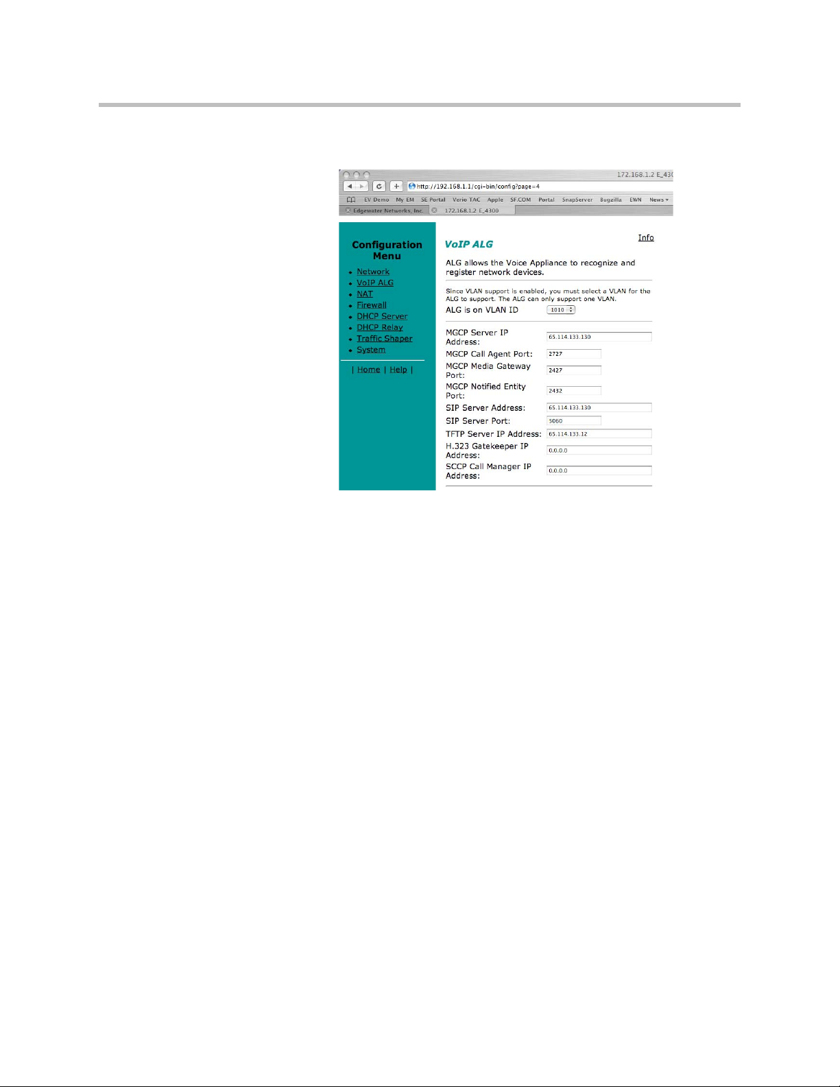
Configure the VoIP ALG
In order to configure the VoIP ALG the 4300T must be told where to reach the
signaling servers and TFTP server on behalf of the voice devices.
Configuring the 4300T
example, when using WiFi or moving office locations. In these instances
the IP address of the voice and video device may be changed.
1. Select VoIP ALG.
2. If using VLANs assign the ALG to a specific VLAN id using the drop
down menu.
3. If you are using MGCP enter the MGCP Server IP Address, MGCP Media
Gateway Port and MGCP Notified Entity Port.
4. If you are using SIP enter the SIP Server IP Address and SIP server port.
The SIP server port is the port used by the SIP registrar. The default
value is port 5060.
5. If you are using H.323 enter the H.323 Gatekeeper IP Address.
3 - 27
Page 46

User Guide V2IU 4300T Converged Network Appliance
6. Enter the TFTP Server Address. This address is used to identify the TFTP
server that contains the images used by IP phones at boot up. The 4300T
performs a TFTP server relay function.
Note
It is not necessary to program in an FTP server address if your IP phones use the
FTP protocol instead of TFTP to retrieve their images. A relay function is not
needed for FTP as the 4300T will forward FTP traffic to the destination server as
programmed in your IP phone.
3 - 28
7. Automatic MGCP Re-registration is used to re-register MGCP endpoints
every time the network or system restarts. Enable this feature to
automatically synchronize the softswitch and phones immediately after a
restart. The default is Enabled.
8. The MGCP Re-registration Rate is used to set the number of MGCP RSIP
messages to send per second to the Media Gateway Controller when
re-registration is needed. If the MGCP Re-registration Rate needs to be
changed, enter a value between 1 and 5. Generally, this value does not
need to be modified. The default value is 5 msg/second.
9. The system re-registers clients when it starts up. If any of these
re-registration requests fail, the system will wait for the configured
number of seconds and then retry the re-registration for the clients that
failed. The system will make at most 10 re-registration requests for failed
attempts. If the MGCP Re-registration Retry Delay needs to be changed,
enter a value between 30 and 60 seconds. Generally, this value does not
need to be modified. The default value is 30 seconds.
10. The H.323 TerminalType is used to specify the type of terminal that the
Voice Appliance should use. It can be either endpoint or gateway. The
Maximum Bandwidth specifies the bandwidth to allow for H.323 calls.
Page 47

Configuring the 4300T
The bandwidth is specified in kbps and if it is set to 0, bandwidth
management is not enforced. Only calls with media traversing the 4300T
is counted towards the bandwidth maximum.
11. The Current payload bandwidth calculates the current video traffic,
without IP overhead, traversing the Appliance. The Estimated total
bandwidth calculates the total video traffic, plus IP overhead, traversing
the Appliance.
12. The H.323 Max Aliases limits the number of aliases that are allowed to
register with the Voice Appliance. If this number is exceeded when a
client tries to register, the registration will be rejected. If the value is set to
0, the maximum is not enforced.
13. The SIP LAN Side Gateway is used to configure a LAN side SIP gateway
to which calls that are not for a registered phone can be sent. The name of
the gateway is the name that is configured for the gateway in the
soft-switch and the IP address is the address where the gateway can be
reached.
14. Press Submit.
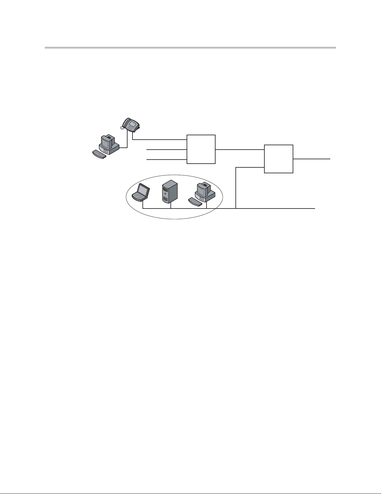
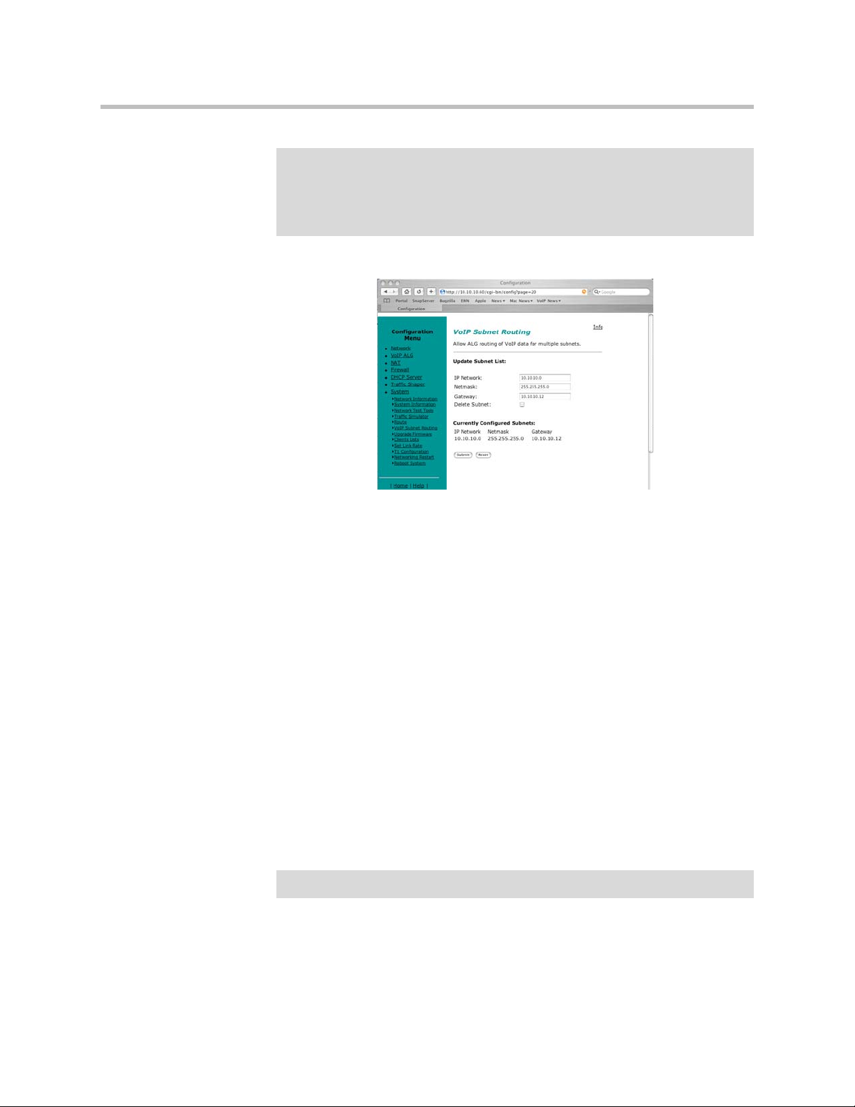
Configure VoIP Subnet Routing
It is not necessary to configure VoIP subnet routing if all of your voice and
video devices are installed on the same IP subnet as the 4300T. In some
installations the voice and video devices are located in different subnets than
the 4300T and connected via intermediate routers. In these instances it is
necessary to configure a return path in the 4300T by specifying the
intermediate router who knows how to reach the voice devices. This router
must be reachable by the 4300T.
WAN
V2IU
IP Phones
Router
Subnet BSubnet B
EM007B
3 - 29
Page 48
User Guide V2IU 4300T Converged Network Appliance
Note
VoIP Subnet Routing is separate and independent from static data routes (see
Static IP routing). VoIP subnet routes must be configured for each LAN subnet that
contains devices making use of the 4300T’s Application Layer Gateway (ALG).
These entries tell the ALG that the identified subnet is allowed to make use of its
services and what router the ALG should use to reach that subnet.
Enter a VoIP Subnet Route
1. Select System.
Note
2. Select System Overview.
3. Select VoIP Subnet Routing.
4. Enter the IP Network (e.g. 10.10.12.0).
This is the IP address of the remote subnet containing the voice devices.
5. Enter the Netmask (e.g. 255.255.255.0).
This is the mask of the IP address of the subnet containing the voice
devices.
6. Enter the Gateway (e.g. 10.10.10.2).
This is the IP address of the intermediate router that knows the return path
to the remote subnet from the 4300T.
7. Press Submit.
Perform steps 1 through 7 for each remote subnet containing the voice devices.
The 4300T is limited to a total of 20 different VoIP subnets.
Delete a VoIP Subnet Route
1. Select System.
3 - 30
Page 49

Configuring the 4300T
2. Select System Overview.
3. Select VoIP Subnet Routing.
4. Enter the IP Network (e.g. 10.10.12.0) .
This is the IP address of the remote subnet containing the voice devices.
5. Enter the Netmask (e.g. 255.255.255.0).
This is the mask of the IP address of the subnet containing the voice
devices.
6. Enter the Gateway (e.g. 10.10.10.2) .
7. This is the IP address of the intermediate router that knows the return
path to the remote subnet from the 4300T.
8. Select the Delete Subnet checkbox.
9. Press Submit.
Perform steps 1 through 8 for each remote subnet that you wish to delete.
Configure IP Phones, IADs or Softphones
After configuring the 4300T VoIP ALG the voice devices must be configured
to point to the LAN interface of the 4300T as their signaling gateway and
optionally as their TFTP server (if they use the TFTP protocol to retrieve their
software images). The steps required to setup these devices differ from vendor
to vendor. Using the DHCP server included in the 4300T will significantly
simplify the setup of these devices if they are able to obtain their IP
configuration via DHCP. Please consult the applicable users guide of each
device for detailed instructions.
3 - 31
Page 50
User Guide V2IU 4300T Converged Network Appliance
Data Networking Configuration
The 4300T provides static IP routing and two types of Network Address
Translation (NAT) functions for data traffic. This section describes the use and
configuration of these features.
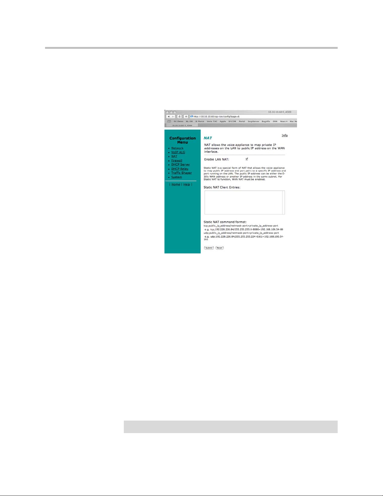
NAT for Data Traffic
Note
3 - 32
NAT allows hosts on a private internal network (the LAN side of the 4300T) to
anonymously communicate with devices on an external network (the WAN
side of the 4300T). The 4300T with NAT enabled will re-write outbound
packet headers using public IP addresses in place of private IP addresses so
that the private IP addresses are not exposed to the external network.
Additionally, the ports used by the IP addresses are also changed as they
traverse the 4300T. This is known as Port Address Translation (PAT) and
provides an additional security measure. The 4300T maintains a table of these
mappings so that return packets can be forwarded to the correct host on the
private network.
The 4300T provides two types of NAT functions: dynamic NAT and static
NAT. Dynamic NAT allows many private IP addresses to be mapped to a
single public IP address (using different port numbers of the public IP
address). Static NAT maps private IP addresses and port. For example,
mapping a public IP address to a specific machine on the private network
responsible for receiving email.
The 4300T ALG automatically handles NAT for voice devices.
Page 51

Configuring the 4300T
Configure Dynamic NAT
Use Dynamic NAT when you have multiple PCs installed on the LAN side of
the 4300T that require Internet or WAN access. Once Dynamic NAT is enabled
the 4300T will automatically perform an address translation for all packets
to/from the LAN side PCs.
1. From the Configuration Menu select NAT.
2. Use the Enable Lan NAT checkbox to enable or disable dynamic NAT.
The default value for dynamic NAT is enabled.
3. Press Submit.
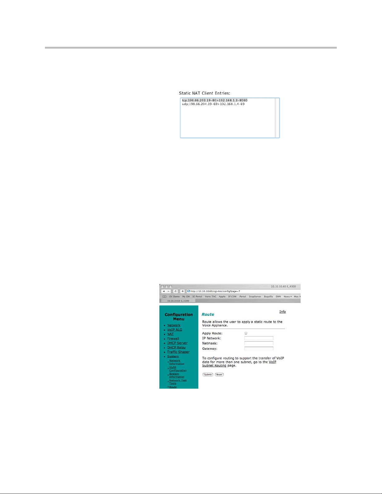
Configure Static NAT
Use Static NAT when a server or PC located in the private network needs to be
accessible from the external network. Some examples include a corporate web
server, a mail server or an FTP server. In these instances, the 4300T statically
maps the public IP address of each server to the actual private IP address of
the server.
Note
In order for Static NAT to function dynamic NAT must be enabled.
1. Select NAT.
2. Enter the public and private IP addresses and ports to be mapped in
Static NAT Client Entries using the following format:
Protocol;PublicIPAddress/netmask-port>PrivateIPAddress-port
For example, the entry “tcp;198.66.203.19-80>192.168.1.3-8080” will map
all web traffic destined to public IP address 198.66.203.19 to the private
webserver 192.168.1.3 port 8080. The public IP address of 198.66.203.19 is
automatically created as a “subinterface” or “secondary address” on the
WAN interface of the 4300T so that external hosts can reach the web
server.
Each entry should be placed on a new line.
3. Press Submit.
3 - 33
Page 52
User Guide V2IU 4300T Converged Network Appliance
Delete a Static NAT entry
1. Select NAT.
2. To delete an IP address or a range of IP addresses highlight the entry in
the Static NAT Client Entries list and press the Delete key on your
keyboard.
3. Press Submit.
Static IP routing
In addition to locally connected IP networks the 4300T can forward traffic for
a remote data network by configuring a static route entry. Any packets
destined for the remote data network will be forwarded to the specified
gateway address in the entry.
Configure the static route
1. Select System.
3 - 34
2. Select System Overview.
3. Select Route.
Page 53

Configuring the 4300T
4. Select the Apply Route checkbox.
5. Enter the IP Network address. This address is the remote data network
you would like the 4300T to forward to the gateway. The hosts portion of
the IP address should be set to “0”. For example, 10.10.20.0
6. Enter the Netmask of the remote data network. For example,
255.255.255.0
7. Enter the Gateway IP address of the interface that will receive all packets
destined for the remote data network.
8. Press Submit.
Delete the static route
1. Select System.
2. Select System Overview.
3. Select Route.
4. Remove the check in the Apply Route checkbox.
5. Press Submit.
Firewall Configuration
3 - 35
Page 54

User Guide V2IU 4300T Converged Network Appliance
The 4300T uses a Stateful Packet Inspection (SPI) firewall to protect data
devices installed behind the LAN interface. Voice devices are protected by the
4300T Application Layer Gateway (ALG) as described in VoIP Configuration.
The firewall is enabled by default. The default behavior of the firewall is to:
• deny all traffic originating from the WAN
• allow all traffic originating from the LAN
• allow only return traffic for connections that originated from the LAN
• deny all traffic originating from the WAN to the 4300T itself
• allow all traffic originating from the LAN to the 4300T
The default behavior can be modified using the basic and advanced settings
fields on the firewall configuration page. We recommend that you use the
4300T firewall, however it can be disabled if the 4300T is installed behind an
existing legacy firewall.
Enable or disable the firewall
1. Select Firewall.
Warning
2. Use the Enable Firewall checkbox to either enable or disable the firewall.
3. Select Submit.
Configure Basic settings
To allow or deny HTTP, Telnet and SSH traffic originating from the WAN to
the 4300T simply use the checkboxes provided in the basic settings area of the
firewall configuration page. By default, access from the WAN into the 4300T
is disabled.
Denying HTTP, Telnet or SSH traffic from the WAN may result in losing
management connectivity to the 4300T if you are configuring the system remotely
using the WAN link.
1. Select Firewall.
2. Use the three Allow access from WAN side checkboxes to enable or
disable HTTP, Telnet, and/or SSH access from IP devices on the WAN
side of the 4300T.
3. Select Submit.
Configure Advanced Settings
3 - 36
A comprehensive security policy can be created using the advanced settings of
the 4300T firewall. The policy actions that can be taken on any packet
processed by the 4300T are summarized in the following table:
Page 55

Action Description Input format
Configuring the 4300T
Allow TCP Port Allows traffic with the
specified TCP port to
terminate on the 4300T.
Allow UDP Port Allows traffic with the
specified UDP port to
terminate on the 4300T.
Deny Hosts (IP) Denies all traffic with the
source IP address
matching the specified
hosts
Deny Hostwise
TCP (IP-Port)
Denies all traffic
matching the specified
TCP port numbers and
the specified source IP
addresses
Deny Hostwise
UDP (IP-Port)
Denies all traffic
matching the specified
UDP port numbers and
the specified source IP
addresses
*Valid values ra ng e from 1 through 65535. *Multiple
entries are separated by a space
*Range value specified by : character. For example,
25:50 means perform the action on ports 25 through 50
*Valid values ra ng e from 1 through 65535. *Multiple
entries are separated by a space
*Range value specified by : character. For example:
25:50 means perform the action on ports 25 through 50
*Multiple entries are separated by a space
*Classful IP addresses are assumed by default. For
example: 192.168.3.1 uses a class c mask. Subnets can
be specified using the / notation. E.g. 192.168.3.1/24
*Multiple entries are separated by a space
*Port are specified using a - character. For example:
192.168.3.1-23 for Telnet.
*Port ranges are specified using a : character. For
example: 192.168.3.1-23:50 means port 23 through 50
*Classful IP addresses are assumed by default. For
example: 192.168.3.1 uses a class c mask. Subnets can
be specified using the / notation. E.g. 192.168.3.1/24
Allow Hostwise
TCP (IP-Port)
Allows all traffic matching
the specified TCP port
numbers and the
specified source IP
addresses
*Multiple entries are separated by a space
*Port are specified using a - character. For example:
192.168.3.1-23 for Telnet.
*Port ranges are specified using a : character. For
example: 192.168.3.1-23:50 means port 23 through 50
*Classful IP addresses are assumed by default. For
example: 192.168.3.1 uses a class c mask. Subnets can
be specified using the / notation. E.g. 192.168.3.1/24
3 - 37
Page 56

User Guide V2IU 4300T Converged Network Appliance
Allow Hostwise
UDP (IP-Port)
Allows all traffic matching
the specified UDP port
numbers and the
specified source IP
addresses
If a given packet does not match any of the configured rules, it is dropped.
1. Select Firewall.
2. Enter the desired Advanced Settings using the table above as a guide.
3. Select Submit.
Remove Advanced Setting Entries
To remov e an a dvan ced fi rewa ll se ttin g sim ply hi ghli ght t he va lue i n the e ntry
box and delete it using the keyboard.
*Multiple entries are separated by a space
*Port are specified using a - character. For example:
192.168.3.1-23 for Telnet.
*Port ranges are specified using a : character. For
example: 192.168.3.1-23:50 means port 23 through 50
*Classful IP addresses are assumed by default. For
example: 192.168.3.1 uses a class c mask. Subnets can
be specified using the / notation. E.g. 192.168.3.1/24
1. Select Firewall.
2. Highlight the entry to be deleted in the Advanced Settings list and press
the Delete key on your keyboard.
3. Press Submit.
Traffic Management Configuration
Traffic management is required to ensure high quality voice and video calls
when voice, video, and data traffic share the same WAN link. Voice and video
traffic must be prioritized for transmission over data traffic to meet the
stringent jitter, latency and packet loss requirements for high quality voice and
video. The 4300T:
• Automatically prioritizes voice and video traffic over data traffic to ensure
high quality voice and video calls.
• Maximizes WAN link utilization by allowing data traffic to burst up to full
line rate in the absence of voice and video calls.
3 - 38
Page 57

Configuring the 4300T
• Controls the data transfer rate of far-end WAN TCP devices to limit WAN
link congestion.
• Supports network-based QoS applications by setting the TOS bits for all
VoIP packets sent to the WAN and the LAN. TOS bits are used so that
VoIP packets can be prioritized in the network by DiffServ enabled
routers. The TOS bit value used by the 4300T is to “minimize delay and
maximize throughput”, or 0xb8 hexadecimal. This value is set for all VoIP
packets processed by the 4300T and overwrites any specific TOS bit
configuration set by VoIP endpoints.
• Ensures that bandwidth allocated to new voice and video calls does not
adversely affect the quality of existing active calls (Call Admission Control
or CAC).
The 4300T combines sophisticated traffic management mechanisms including
classification, prioritization, queuing, rate limiting and CAC to ensure high
quality voice and video calls. Fortunately the system manages this complexity
for you and configuring traffic management is very straightforward:
1. Enable traffic shaping.
2. Specify the upstream and downstream bandwidth of your WAN link.
3. Enable CAC.
Please follow the steps below to configure and enable traffic management.
Enable Traffic Shaping
1. From the Configuration Menu, select Traffic Shaper.
2. Select the Enable traffic shaper checkbox.
3 - 39
Page 58

User Guide V2IU 4300T Converged Network Appliance
3. Specify the upstream and downstream bandwidth of your WAN link
4. Enter the WAN Downstream Bandwidth in Kbps.
5. Enter the WAN Upstream Bandwidth in Kbps.
Note
For FT1/T1/E1 links the upstream and downstream bandwidths will always be the
same value (the link is full-duplex).
Optionally enable priority IP addresses
VoIP traffic from devices that use the VoIP ALG function (phones, video
stations, softphones on Pcs, etc.) are already marked as high priority and do
not need to be manually configured in this list. This list is used to prioritize
voice traffic from trunk interfaces of IP PBXs or other high priority devices that
do not use the VoIP ALG function of the 4300T.
>>
Enter the IP address of other high priority devices in the priority IP
Addresses box.
You can enter individual IP addresses or a range using by appending a “-“
character to the last octet. For example, 10.10.10.2-5 would specify
10.10.10.2, 10.10.10.3, 10.10.10.4 and 10.10.10.5 as voice devices.
Warning
Care must be taken to ensure that the IP addresses entered do not include data
devices such as PCs or workstations. Traffic from these devices will be placed in
the priority voice queue internal to the 4300T and burst up to full line rate. This will
starve actual voice devices by consuming priority bandwidth and result in dropped
calls, busy signals & poor voice quality.
Enable CAC
3 - 40
The 4300T uses CAC to limit the number of active voice calls over the WAN
link. This is necessary because a typical installation uses a ratio of 1:2 or 1:4
active voice calls to voice devices on the assumption that 50% or 25% of all
users are on the phone at the same time. These ratios are guidelines only and
at times the number of concurrent calls may exceed the amount of WAN
bandwidth available to process the calls. In this instance existing phone calls
will experience poor quality or be dropped all together. To prevent this from
occurring a typical voice installation will set a threshold for the maximum
number of concurrent voice calls supported by the WAN access link. New call
requests in excess of this threshold will receive the equivalent of a “fast busy”
and the WAN link will not become oversubscribed.
For IP Centrex installations the maximum number of concurrent voice calls is
usually configured in the 4300T by enabling CAC. When the 4300T is
deployed in IP PBX applications the maximum number of concurrent calls
co uld be confi gure d in th e IP PB X. If the PBX is responsible for this setting you
do not need to configure CAC in the 4300T. Please check with your IT
administrator to determine if this is the case.
Page 59

Configuring the 4300T
Determining the maximum number of concurrent calls
The maximum number of concurrent calls that can be supported by the WAN
access link is calculated using the following formula:
Max calls = (Maximum WAN upstream bandwidth * .85)/VoIP codec rate
where,
Maximum WAN upstream bandwidth = value entered in step D above (in
Kbps)
VoIP codec rate = 85.6Kbps for G.711 voice devices or 29.6Kbps for G.729 voice
devices.
The maximum WAN upstream bandwidth is multiplied by .85 in the formula
above to reduce the total bandwidth available for voice calls by 15%. This
reduction is necessary because the 4300T automatically reserves 15% of the
total WAN bandwidth for low priority data traffic so that it is not starved
completely. Starving data traffic completely would increase the number of
retry attempts and exacerbate congestion on the link during periods of peak
usage.
Examples
The maximum number of G.711 voice calls supported by a T1 (1.536 Kbps)
WAN is calculated as follows:
(1.536*.85)/85.6 = 15.3 or 15 total voice calls.
The maximum number of G.711 voice calls supported by a 768Kbps fractional
T1 WAN is calculated as follows:
(768*.85)/85.6 = 7.6 or 7 total voice calls
The maximum number of G.729 voice calls supported by a 256Kbps fractional
T1 WAN is calculated as follows:
(256*.85)/29.6 = 7.4 or 7 total voice calls
After determining the maximum number of voice calls CAC is enabled as
follows:
1. Select the Enable Call Admission Control checkbox.
2. Enter Maximum number of calls allowed as calculated above.
3. Press Submit.
A Closer Look at Traffic Management in the 4300T
The traffic management mechanisms provided by the 4300T are designed to
ensure high priority real-time voice and video traffic is processed before lower
priority data traffic. At the same time, bandwidth not in use by voice and
video traffic is made available so that data traffic can burst up to full line rate
making efficient use of WAN bandwidth. Traffic management mechanisms
3 - 41
Page 60

User Guide V2IU 4300T Converged Network Appliance
are applied to traffic in both the upstream (LAN to WAN) and downstream
(WAN to LAN) direction. Each direction is independent of the other and can
support different size priority queues.
Classifying
High priority voice and video traffic generated by endpoint devices is
automatically identified by the V
Other VoIP devices (not making use of the ALG) can be defined as
high-priority by their IP address. The user configures these addresses into the
priority list in the Traffic Shaper section of the 4300T web GUI.
As the 4300T processes packets they are identified as either high or low
priority based on this configuration. Packets identified as high priority are
marked as such in the TOS bits of their IP header, allowing prioritization by
downstream routers. The TOS field is set to 12 hexadecimal “minimize delay
and maximize throughput” This value overwrites any prior value.
Upstream Traffic Management
The 4300T appliance uses a combination of Class Based Queuing and simple
classless queuing to send data in the upstream direction. The Class Based
Queue (CBQ) consists of two priority classes (high and low), a scheduler to
decide when packets need to be sent, and a traffic shaper to rate-limit by
delaying packets before they are sent. Each of these is described in more detail
below.
Priority classes
Voice and video traffic is placed in the high-priority queue and data traffic is
placed in the low-priority queue. The IP header TOS field of packets in the
high-priority queue is set to “minimize delay and maximize throughput”.
2
IU’s VoIP Application Layer Gateway.
3 - 42
Scheduler
High-priority data is polled before low priority data, thereby minimizing the
latency for voice and video traffic. High-priority data is allowed to use up to
85% of the total WAN bandwidth. Although preferential treatment is given to
high-priority data, 15% of the WAN link is always reserved so that
low-priority data is not starved.
High priority data is polled before lower priority data to reduce overall latency
for voice traffic.
Traffic shaper
To smooth bursts from high speed data links (typically from the LAN Ethernet
heading to the WAN) the 4300T appliance uses a buffer that clocks data out at
rates not exceeding automatically-calculated maximums. Low-priority data is
Page 61

clocked out at the WAN link’s full rate LESS the bandwidth currently being
used for high-priority (ie voice) data. High-priority data is clocked out at the
WAN’s full link rate. Any long-lasting burst condition in low-priority data
will cause these packets to be delayed and, if necessary, dropped.
Downstream Traffic Management
Since the 4300T is the final transmitting device for WAN traffic in the upstream
direction (LAN to WAN) it is easy to see how its QoS mechanisms can be
applied to traffic it is transmitting to guarantee sufficient bandwidth for voice
traffic. We have control over how packets are handed to the WAN interface.
In the downstream direction (WAN to LAN) we are installed at the receiving
end of a service provider link and therefore have no control over the amount
of voice or data traffic being sent to us over the WAN interface. How then can
we still guarantee the quality of in-bound voice traffic when it is entirely
possible for an FTP session, for example, to consume the vast majority of
downstream bandwidth?
Fortunately this is possible by shaping on both the egress LAN and egress
WAN ports of the 4300T appliance and leveraging the congestion avoidance
mechanisms built into TCP. Essentially, data packets received by the 4300T’s
WAN interface at a rate that exceeds the T1’s bandwidth LESS the bandwidth
used for active voice calls are delayed (then dropped if necessary) before being
forwarding on to its LAN interface. Similarly, data traffic sent back to the
4300T for transmission to the WAN are also delayed (as described in the above
section). This results in the WAN-based devices following the rules of TCP/IP
congestion avoidance and slowing down their transmit rate. This technique is
quite effective in practice, as end stations usually reduce their transmit rate
before VoIP signaling has completed for new call setup.
Configuring the 4300T
For example consider the scenario where there are no voice calls over a WAN
link and multiple FTP sessions are consuming all available bandwidth:
1. A new call request is received by the 4300T from the WAN.
2. All signaling messages for the call are classified as voice traffic and
therefore prioritized for transmission to the LAN before servicing the
inbound FTP data.
3. RTP traffic (the voice data within an ongoing VoIP session) is similarly
classified as voice traffic and treated with priority.
4. FTP data is buffered (or dropped) by the 4300T and return data, including
the FTP ACKs, are also delayed. This results in a throttling of the
transmit rate by the (far-end) FTP hosts, reducing overall WAN
bandwidth consumption.
Generally, excessive UDP traffic must be shaped in the service provider
network, as UDP does not provide congestion avoidance mechanisms. The
exception to this is in the case of RTP UDP-based messages for voice traffic.
3 - 43
Page 62

User Guide V2IU 4300T Converged Network Appliance
Although RTP makes use of UDP the 4300T appliance is able to provide its
own congestion avoidance mechanism for voice traffic using Call Admission
Control (CAC).
VoIP Survivability Configuration
The high availability of voice services is a fundamental requirement for
enterprises deploying their own IP telephony equipment or subscribing to
hosted VoIP services. In both cases providing reliable communications to
remote branch offices is costly usually involving the installation of local call
processing servers or additional wide area network (WAN) links to these
locations.
Polycom’s VoIP survivability enhances the reliability of VoIP services to
branch offices in a cost effective manner by providing local call switching in
the event of WAN link failures or a loss of connectivity to network based call
processing servers. VoIP survivability is an orderable software option for
Polycom’s V
devices that can also be configured to provide IP routing, optional T1 WAN
link termination, resolve NAT/firewall traversal problems, ensure high
quality voice using QoS, monitor voice call quality and provide
comprehensive security for the LAN using a VoIP and data firewall.
2
IU Series appliances. V2IU appliances are flexible networking
Key benefits and features of VoIP survivability
Polycom’s VoIP survivability offers the following important benefits:
• Continuity of voice services to branch offices during WAN link failures or
failures in network based call processing servers
• Significant savings over alternative solutions requiring redundant call
processing servers or multiple WAN links
• Simplified design that is easier to manage than alternative solutions
requiring maintenance of multiple dial plans in distributed call processing
servers and complex routing
Survivability features:
• Application layer based monitoring of call processing servers to
determine connectivity
• Automatic detection of loss of connectivity to call processing servers
caused by WAN link failures, network congestion or call processing server
software failure
• Automatic return of call control to network based call processing servers
once connectivity has been restored
• Configurable timers to determine call processing server connectivity
3 - 44
Page 63

Configuring the 4300T
• Call processing server connectivity status indicators
• Support for multiple call processing servers using DNS
• Reporting of the currently active call processing server in environments
using multiple call processing servers
• Local call switching between VoIP endpoints and premises based PSTN
gateways during WAN link failures or other failures that prevent
connectivity to network based call processing servers
• Calling features such as transfer, hold and conference are provided by
2
V
IU Series appliances
• Simplified setup that creates a local dial plan in the V
How survivability works
The V2IU appliance automatically creates a local dialing plan by monitoring
the registration requests sent by LAN based SIP user agents as they register
with the network based call processing server. In creating this dial plan the
2
V
IU appliance now has knowledge of all local SIP user agents installed on its
LAN interface. This dial plan will be used during fallback mode of operation
when the V
and/or a LAN side PSTN gateway.
2
V
IU appliances continuously monitor the status of connectivity to network
based call processing servers using application layer heartbeat messages.
Configuration settings in V
to the call processing server and how quickly the server will be declared
unreachable in the event of a failure. The use of application layer messages
provides the added benefit of detecting the failure condition where an V
appliance has IP connectivity to the call processing server but the call
processing server software itself is not functioning properly.
Once a call processing server has been declared unreachable V
enter fallback mode and perform call processing for local SIP user agents. A
SIP PSTN gateway can also be installed at the branch office on the LAN side of
the V
fallback mode. To maximize utilization of this gateway it can also be used
when call switching is being performed by the network based call processing
server.
2
IU appliance by
monitoring traffic to network based call processing servers
2
IU appliance provides local call switching between user agents
2
IU appliances control how often messages are sent
2
IU appliances
2
IU appliance and used for inbound and outbound calling during
2
IU
Once connectivity to the network based call processing server is restored the
2
V
IU appliance will automatically turn control of all subsequent call requests
over to the softswitch. Calls in progress that were established while the V
2
IU
appliance was in fallback mode will not be disrupted when connectivity is
restored to the network based call processing server.
Redundant or multiple call processing servers can be used in conjunction with
2
V
IU Series appliances to further enhance the availability of voice services.
2
V
IU appliances will use DNS SRV records from a DNS server to obtain a
3 - 45
Page 64

User Guide V2IU 4300T Converged Network Appliance
prioritized list of available network based call processing servers. The V2IU
appliance using periodic messages monitors each server and the highest
priority server that is currently reachable will be used for call processing. This
feature can also be used to load balance or distribute calls among multiple
servers however state replication is required by the call processing servers to
provide full redundancy.
Platform Support
V2IU Converged Network Appliances
• 4300T Series
• 5300 Series
• 6400 Series
IP Phones
• Polycom IP500 & IP600
• Cisco
PSTN Gateways
• Audiocodes MP-104/108
Configuring VoIP Survivability in V2IU Appliances
Configuring VoIP survivability in V2IU appliances consists of the following
tasks:
1. Enable VoIP survivability.
2. Configure call processing server reachability settings (optional).
3. Specify the number of digits to use for local dialing (optional).
4. Configure the IP address of the local LAN side PSTN gateway (optional).
5. Configure call processing server redundancy (optional).
Please note that this configuration requires that you have completed the basic
installation of the V
and VoIP configurations. Information regarding these tasks can be found in
the “info” section of the V
2
IU appliance including interface, IP, traffic management
2
IU appliance, or the User Manual.
3 - 46
Page 65

Step 1 – Enable VoIP Survivability
2
1. Log into the V
IU appliance using a Netscape or Internet Explorer web
browser.
2. Select System.
3. Select Survivability.
Configuring the 4300T
4. Select the Enabled radio button under the Survivability Configuration
section of the web page.
5. Press Submit.
2
The V
IU appliance is now configured to check the connectivity of the call
processing server and will automatically perform local call switching if the
server becomes unavailable.
Step 2 – Configure call processing server reachability settings (optional)
The reachability settings control how often messages are sent to network
based call processing servers and how quickly a server will be declared
unreachable or reachable. These settings can be changed to match the
particular needs of your environment by using the following steps:
3 - 47
Page 66

User Guide V2IU 4300T Converged Network Appliance
1. Log into the V2IU appliance using a Netscape or Internet Explorer web
browser.
2. Select System.
3. Select Survivability.
4. Enter the desired values for Time between heartbeat messages, Time to
declare heartbeat lost, Number of lost messages to declare alarm and
Number of received messages to clear alarm in the Softswitch
Reachability section of the web page.
5. Press Submit.
The reachability settings are used to determine when the V
provides local call switching by entering fallback mode and when it returns
call control to network based call processing servers. The definitions of the
reachability settings are as follows:
Time between heartbeat messages - The number of seconds between each
heartbeat message sent to the call processing servers to determine
connectivity.
Time to declare heartbeat lost – The number of seconds that the V
will wait before declaring a response to a heartbeat message lost.
2
IU appliance
2
IU appliance
Number of lost messages to declare alarm - the number of consecutively lost
responses to heartbeat messages required for the V
2
IU appliance to declare a
loss of connectivity to the network based call processing server.
Number of received messages to clear alarm - the number of consecutively
received responses to heartbeat messages required for the V
2
IU Appliance to
declare successful connectivity to the network based call processing server.
The formula used to determine the maximum time for the V
2
IU appliance to
declare a loss of connectivity to a call processing server is: maximum time =
(X * Y) + Z, where,
X = Time between heartbeat messages
Y = Number of lost messages to declare alarm
Z = Time to declare a heartbeat lost
The default value for X, Y and Z in the V
2
IU appliance is 5. Therefore, the
default maximum time to declare a call processing server unreachable is 30
seconds or ((5*5) + 5).
Step 3 - Specify the number of digits to use for local dialing
This field is the number of digits that the V
when providing local call switching. By default the V
2
IU appliance will use for dialing
2
IU appliance will use 4,
7 and 10 digit dialing. Please follow the steps below if you would like to use a
different number of digits:
1. Log into the V
2
IU appliance using a Netscape or Internet Explorer web
browser.
3 - 48
Page 67
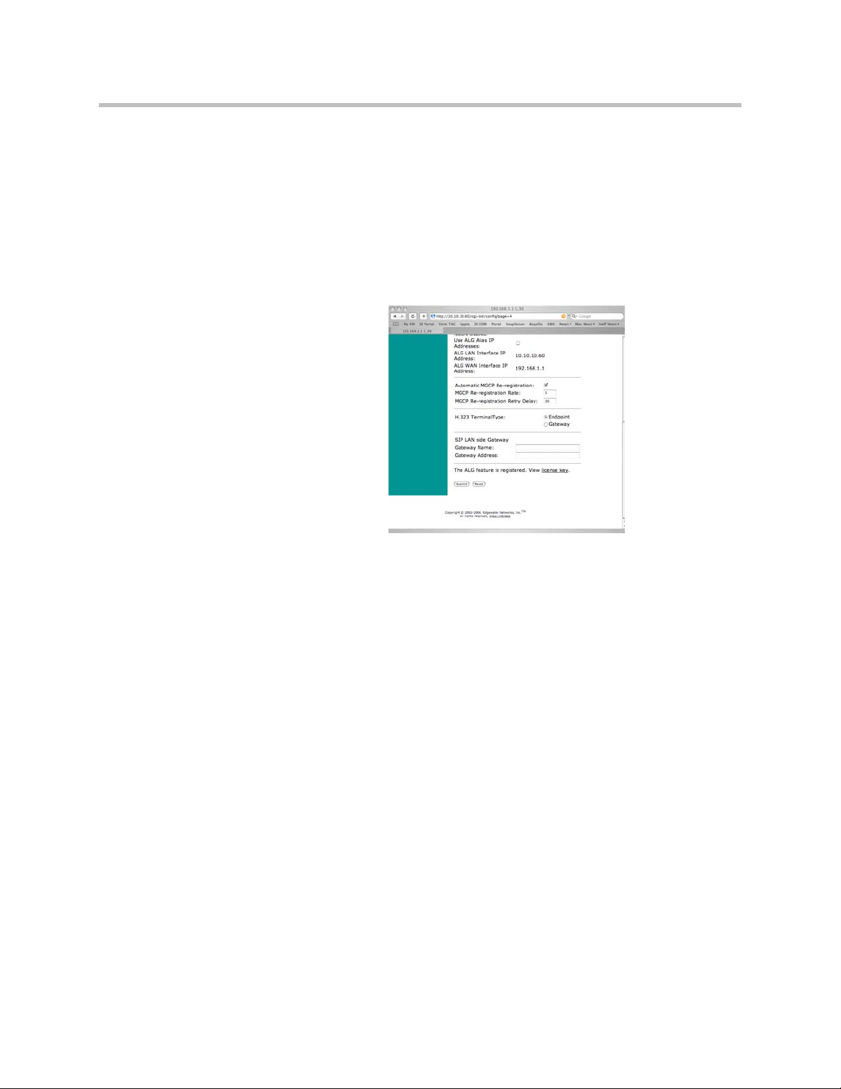
Configuring the 4300T
2. Select System.
3. Select Survivability.
4. Enter the number of digits for local dialing in the Local Dial Plan section
of the web page.
5. Press Submit.
Step 4 - Configure the IP address of the local LAN side PSTN gateway (optional)
This step should be used if you have installed a PSTN gateway at the branch
of fice locat ion. In thi s cas e the I P add ress o f the LAN sid e PST N gate way mu st
be configured in the V
2
IU appliance to support inbound and outbound PSTN
calling while in fallback mode of operation. This gateway resource may also
be used by network based call processing servers when the WAN link is
operational. In fallback mode when the call processing server cannot be
reached the V
2
IU appliance will route outbound calls to the LAN side PSTN
gateway if a number is dialed that is not stored in its local dial plan (e.g. a local
SIP user agent).
1. Log into the V
2
IU appliance using a Netscape or Internet Explorer web
browser.
2. Select System.
3. Select Survivability.
4. Press Submit.
3 - 49
Page 68

User Guide V2IU 4300T Converged Network Appliance
Step 5 - Configure call processing server redundancy
If you will be using multiple network based call processing servers then you
will need to enable server redundancy and specify the time between DNS
lookups in the V
provide a list of multiple call processing servers to the V
answers to SRV lookups. Each server in the list will be monitored using
periodic messages by the V
is currently reachable will be used for signaling. The V
reachability settings described in step 2 to determine the status of remote
servers and remove inoperable servers from the list.
Triggers can also be used by the V
ca ll re ques ts to a seco ndary serv er in the list. A trigger is set when a configured
number of resends are received by the V
attempting to place a call. When initiating a call a SIP user agent will send an
INVITE message to the V
primary server. In the event that the primary server fails before a reachability
alarm has been declared using the heartbeat messages the user agent will
resend INVITE messages until the trigger condition is met. At this point the
2
V
IU appliance will forward the call request on to the secondary server in the
list. Please use the following steps to enable redundancy and set triggers:
1. Log into the V
browser.
2
IU appliance. Enabling redundancy allows a DNS server to
2
IU appliance and the highest priority server that
2
IU appliance to determine when to forward
2
IU appliance from a SIP user agent
2
IU appliance that will then be forwarded to the
2
IU appliance using a Netscape or Internet Explorer web
2
IU appliance in the
2
IU appliance uses the
3 - 50
2. Select System.
3. Select Survivability.
4. Enter the Time between DNS lookups (in seconds) in the Softswitch
Reachability section of the web page.
5. Select Enable SIP server redundancy in the Softswitch Redundancy
Settings section of the web page.
Page 69

Configuring the 4300T
6. Select Trigger on resends in the Softswitch Redundancy Settings section
of the web page.
7. Enter the Number of resends to declare alarm.
8. Press Submit.
3 - 51
Page 70

User Guide V2IU 4300T Converged Network Appliance
3 - 52
Page 71
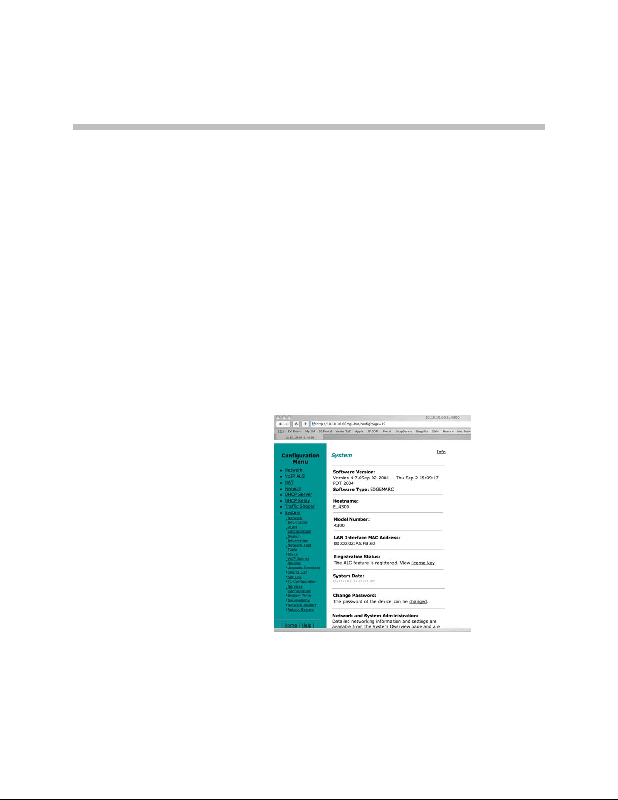
4
System Diagnostics
The 4300T provides a powerful set of diagnostic information, troubleshooting
tools and utilities for system maintenance to network operators.
Viewing Software Version, Hardware Platform and the LAN MAC Address
The software version, hardware platform, and LAN MAC address are
common pieces of information requested by technical support and are
accessed directly through the System page of the 4300T web GUI.
4 - 1
Page 72

User Guide V2IU 4300T Converged Network Appliance
Viewing the ALG registration code
You will also find a link to the ALG registration code on the System page. The
registration code enables the ALG and is pre-installed at the factory. If the
registration code is inadvertently deleted you can re-enter the code using the
following steps:
Enter the Registration Code
1. Select System.
2. Select registration code.
3. Select Edit Registration Code.
4. Enter the Registration Code.
The registration code can be found on the sticker located on the bottom of
the 4300T.
5. Press Submit.
Viewing Networking Information
4 - 2
Page 73

System Diagnostics
To view the networking configuration and status of the 4300T proceed to the
Network Information page as follows:
1. Select System.
2. Select System Overview.
3. Select Network Information.
The following networking information is displayed:
Routing Information
The system routing table contains the static routes for hosts and networks that
are configured on the 4300T. If just the LAN and WAN IP addresses have been
configured there will be four lines displayed:
• The private subnet will be associated with the LAN interface.
• A public subnet present for the WAN interface.
• An entry for the 4300T loopback interface
• The 4300T’s default gateway forwarding to the WAN interface
Additional lines may be displayed depending on the contents of the Route and
VoIP Subnet Routing pages. Each of the entries on these pages will cause an
additional entry in the routing table.
Link Status
Link Status displays the status of the ethernet interfaces. Ethernet
autonegotiation is often unreliable, especially between different vendors or
old and new networking equipment. Failure of autonegotiation is generally
not a cause for concern. However, if the negotiated rates change intermittently
or the link is reported as down or no link, the link rate may need to be set
manually on the Set Link Rate page. Intermittent data and voice outages may
be caused by link flapping when the two endpoints of the Ethernet cable
cannot reach agreement using autonegotiation". If the link rate is set
manually, ensure that the device at the far end of the connection can
communicate at the desired rate. Incompatible rates can cause a loss of
communication with the 4300T.
Link status for the Ethernet ports is displayed via the LEDs adjacent to each
physical port.
Interface Information
The specific status and configuration information for the system interfaces is
displayed in the Interface Information section. HDLC0 shows the interface
statistics for the T1/E1 WAN link. ETH0 shows the interface statistics for the
internal LAN interface between the 4300T processor and the built-in LAN
switch. Interface statistics for the external LAN ports are not displayed.
4 - 3
Page 74

User Guide V2IU 4300T Converged Network Appliance
The interface statistics can point to areas of congestion in the network. If the
errors statistic is a few percent or more of the total packets sent it may be an
indication of excessive congestion on the network interface. If the congestion
is not corrected the quality of voice calls will be affected. The topology of the
network attached to the network interface with the errors should be examined
and modified to better segment and isolate network traffic.
Viewing Advanced System Information
To view advanced system information for the 4300T proceed to the System
Information page as follows:
1. Select System.
2. Select System Overview.
3. Select System Information.
The following system information is displayed:
4 - 4
System Uptime
System Uptime displays the current time, the amount of time elapsed since the
last system reboot, and the system load averages for the past 1, 5, and 15
minutes. Uptime can help trace when a power outage may have interrupted
service. Load averages that remain greater than 2 indicate excessive system
loading. Partitioning voice traffic using a second system may be required.
Process Information
Displays the active processes in the 4300T.
Memory Usage
Displays detailed memory allocation information that may be of use to
technical support.
Page 75
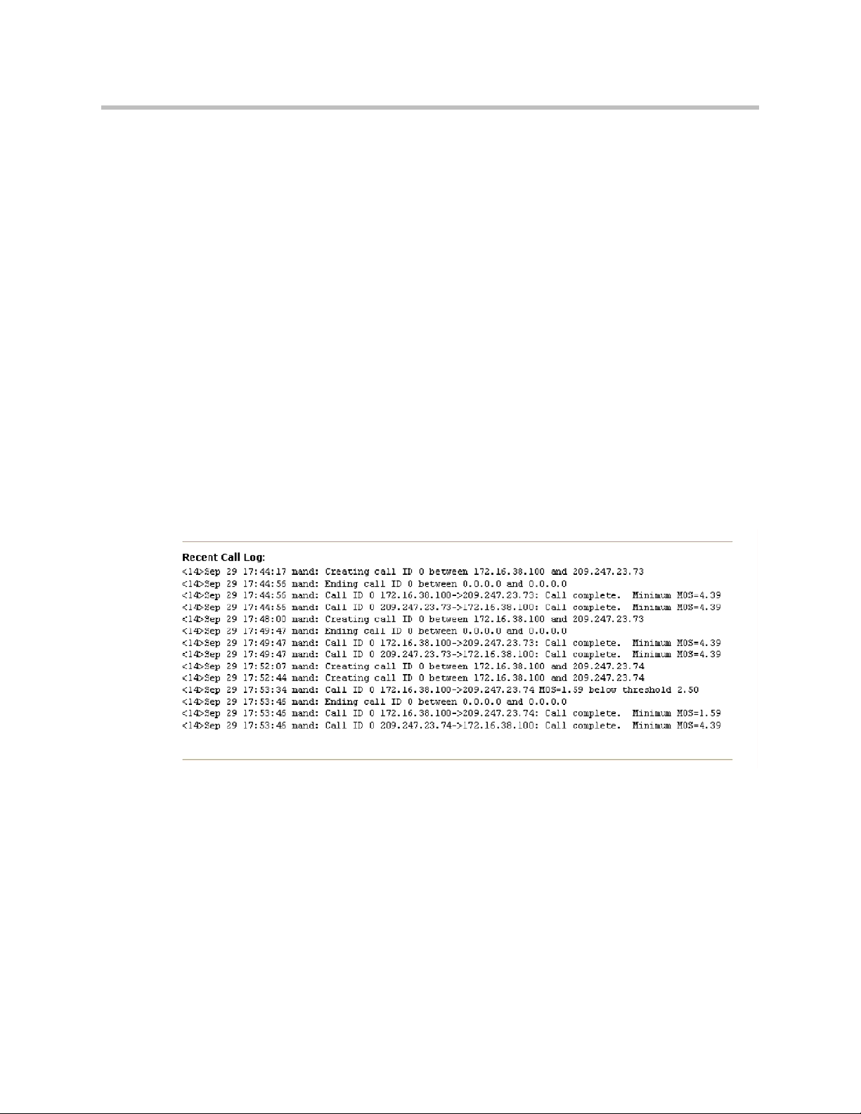
System Logging Messages
Displays information logged during system boot and normal operation.
Logging messages may indicate unauthorized attempts to access the 4300T,
process restart messages, and excessive resource utilization messages.
Passive Voice Call Monitoring
The 4300T monitors live voice calls and performs objective speech quality
assessment. This information enables the network operator to assess voice
quality for the purposes of SLA tracking or problem isolation. Mean Opinion
Score (MOS) results for RTP streams in both directions of a VoIP call are
calculated at call completion. This information along with the IP addresses of
the VoIP endpoints supporting the call are logged locally and optionally sent
to an external syslog server (see Enable Remote System Logging <<<find this
heading>>> for instructions on enabling logging to a remote syslog server).
Additionally the 4300T will generate a real-time message for any MOS values
calculated less than 2.5 (considered poor quality) during an active call.
Voice call quality information is found locally in the System Logging Messages
section of the System Information page and a sample output is provided
below.
System Diagnostics
Accessing Troubleshooting Tools
The 4300T provides convenient test tools to facilitate problem isolation and
resolution. A network operator can use these tools to verify connectivity
to/from the 4300T as well as trace datapaths to endpoints throughout the
network.
4 - 5
Page 76

User Guide V2IU 4300T Converged Network Appliance
Verify Registered Voice and Video Devices
The 4300T maintains a list of all registered voice and video devices called a
clients list so that it can properly route voice and video calls. At startup, voice
and video devices register their IP addresses with the 4300T. The 4300T then
registers on behalf of the voice and video devices by providing its own WAN
IP address to the softswitch, gatekeeper, or IP PBX. If a user or network
operator reconfigures the IP address of the voice or video device (ie. an IP
phone or IAD), it will re-register the new address with the 4300T. In this
instance voice and video calls may be routed improperly because the 4300T
clients list contains out of date information.
To update the clients list simply highlight and delete the stale entry using the
following steps:
1. Select System.
2. Select System Overview.
3. Select Clients List.
4. Proceed to the appropriate signaling section, highlight the duplicate
entry or entries and press the delete key on the keyboard
5. Press Submit.
6. Restart the VoIP ALG by following the instructions found in Restarting
Networking Processes.
4 - 6
Page 77

System Diagnostics
Performing a Ping Test
A ping test is the most common test used to verify basic connectivity to a
networking device. Successful ping test results indicate that both physical and
virtual path connections exist between the 4300T and the test IP address.
Successful ping tests do not guarantee that all data traffic is allowed between
the 4300T and the test IP address but is useful to verify basic reachability.
The following steps are used to perform a ping test:
1. Select System.
2. Select System Overview.
3. Select Network Test Tools.
4. Enter the IP Address to Ping.
5. Press Ping.
The Network Test Tools page will be refreshed and the results of the ping test
are displayed (this may take several seconds). The Reset button is used to clear
the IP address entry used in step D above.
Performing a Traceroute Test
A traceroute test is used to track the progress of a packet through the network.
The test can be used to verify that data destined for a WAN device reaches the
remote IP address via the desired path. Similarly, internal network paths can
be traced over the LAN to verify the local network topology. The following
steps are used to perform a traceroute test:
1. Select System.
2. Select System Overview.
3. Select Network Test Tools.
4. Enter the IP address to Trace.
5. Select either the WAN or the LAN radio button
6. Press Traceroute.
4 - 7
Page 78

User Guide V2IU 4300T Converged Network Appliance
The Network Test Tools page will be refreshed and the results of the traceroute
test are displayed (this may take several seconds). The Reset button is used to
clear the IP address entry used in step D above.
Restarting Networking Processes
In extreme circumstances while troubleshooting you may be asked to restart
the networking processes including the VoIP ALG in the 4300T by technical
support. Use the following steps to restart the networking processes:
1. Select System.
2. Select System Overview.
3. Select Networking Restart.
4. Press restart.
Warning
Warning
Restarting network services will interrupt the system for up to a minute. All voice
and data sessions currently in progress will be interrupted.
Rebooting the 4300T
In extreme circumstances while troubleshooting you may be asked to reboot
the 4300T by technical support. Please use the following steps to reboot the
system:
1. Select System.
2. Select System Overview.
3. Select Rebooting System.
4. Press reboot.
Alternatively a reset can be performed locally by temporarily disconnecting
the power cable from the 4300T.
Rebooting the system will interrupt services for a few minutes. All voice and data
sessions currently in progress will be interrupted.
4 - 8
Page 79

Saving and Restoring the 4300T Configuration
The 4300T stores all configuration information for the system in a series of
individual files that reside in local flash memory. These files are read at boot
time to determine the configuration identity of the 4300T and then stored in
RAM as “running” state. As you configure the 4300T the submit command
writes the configuration changes to both RAM and flash so that the files stored
in flash are always up to date with the running state of the system.
The 4300T provides a utility that enables you to copy the individual
configuration files stored in flash to a single, consolidated backup file. This
single file can then be used as a backup for the entire system and restored at a
later date if necessary. Multiple backup files with different system
configurations can also be created and stored locally in the 4300T or on remote
TFTP servers.
5
Note
The ewn Command
No more than 2 backup files can be stored in the 4300T’s flash due to size
constraints. Also, it is recommended that you create a backup file after any
configuration changes are made to the 4300T. This is to prevent the loss of any
configuration changes made since your last backup in the event that you must
restore the system configuration.
Backup file operations are performed in the 4300T CLI using the ewn
command.
The syntax for the
USAGE:
ewn help|list
ewn save|load|delete [file name]
ewn upload|download [file name] [ip address]
where file name must use extension .conf1 or .conf2
ewn
command is as follows:
5 - 1
Page 80

User Guide V2IU 4300T Converged Network Appliance
The
ewn
command can be used with a local terminal connection or remotely
using SSH.
1. Use a NULL modem cable to connect to serial port 1 of the 4300T
2. Use a terminal emulator such as Hyperterminal set to a baud rate of 9600,
8, 1 and none (databits, stop bits and parity)
Alternatively you can connect to the 4300T remotely using SSH:
1. Logon as root
2. Enter the password
Once you are at the command prompt (#) you can create the backup file, store
it to local flash, copy it to a remote TFTP server, copy it from a remote TFTP
server, delete it, load it or list all available backup files.
Create a Backup File and Save in Local Flash
# ewn save <filename>
Saves the current running configuration.
Filename format (must use extension .conf1 or .conf2):
<filename1>.conf1
<filename2>.conf2
<filenameX> can be a combination of both letters and characters. For example,
EWN30_041503.conf1 or location1_E30.conf2. Trying to use any other
filename format will result in the error message:
“EWN_ERROR_BAD_FILE_NAME”.
Warning
The “.conf” extensions have special significance. If you save a configuration with
<filename-new>.conf1, then any existing <filename-old>.conf1 will be overwritten
with the new one.
Copy a Backup File to a Remote TFTP Server
# ewn upload <filename> <tftp server IP Address>
Copy a backup file from the 4300T to a TFTP server.
Download a Backup File from a Remote TFTP Server
# ewn download <filename> <tftp server IP Address>
Download a backup file from a TFTP server to the V2IU.
List the Available Backup Files
# ewn list
5 - 2
Page 81

Saving and Restoring the 4300T Configuration
List all backup files stored in FLASH. If no file has been saved, the command
will only return the # prompt.
Delete a Backup File
# ewn delete <filename>
Delete the backup file specified in the filename.
Load a Backup File so that it Becomes the Running Configuration
# ewn load <filename>
Loads the specified backup file into RAM and makes it the active running
configuration.
Warning
Issuing this command will automatically restart the 4300T and therefore interrupt
any active voice calls and data sessions.
5 - 3
Page 82

User Guide V2IU 4300T Converged Network Appliance
5 - 4
Page 83

Upgrading the 4300T
This chapter describes how to upgrade your 4300T to the latest software
release available from Polycom.
6
It is recommended that you reboot the 4300T prior to performing the upgrade.
This is to make sure there is enough dynamic memory available to handle the
upgrade process.
Warning
When you update your software telephone services will be unavailable for several
minutes. It is therefore advised that upgrades be performed during a maintenance
window when telephone traffic can be interrupted.
Upgrade Procedure for Software Revision 1.3.11 or Later
Use this procedure if your 4300T is running software revision 1.3.11 or later.
The software version can be found on the System page of the web GUI.
1. Select System.
2. Select System Overview.
3. Select Upgrade firmware.
6 - 1
Page 84

User Guide V2IU 4300T Converged Network Appliance
4. Enter the Download Server address of ftp.support.polycom.com.
5. Enter the Filename: flash.bin
6. Press Submit.
You can follow the progress of the upgrade by selecting the refresh the
upgrade status link.
Warning
Do not change the configuration or power off the device until the write is 100
percent complete. The 4300T may become unusable if the write is interrupted. The
flash write can take up to 5 minutes depending on the speed of the download
server.
The system will automatically restart after the new image has been loaded.
7. Verify that the upgrade was successful by checking the software revision
number found on the System page.
6 - 2
Page 85

Appendix
Troubleshooting Tips
This section contains possible solutions to problems regarding the installation
of the 4300T.
I am having trouble reaching the Internet through the 4300T.
We recommend connecting a PC directly (or via a switch) to the LAN port of
the 4300T. The default LAN IP address of the 4300T is 192.168.1.1 so please be
sure that the IP address of the PC is on the same network (eg. 192.168.1.2).
Once you have connected please verify that the IP configuration information
in the Network page is correct. Some other items to try:
• Ping the WAN interface of the 4300T from the attached PC
• Ping the DNS server for your network. Sometimes connectivity problems
occur when the domain name being used cannot be mapped to the proper
IP address.
• Ping a well known address on the Internet.
• Ping the IP address of the remote softswitch or IP PBX.
I do not receive dial tone when going “off hook” or my phone will not register
with the softswitch/IP PBX.
• Verify the configurations on the VoIP ALG page.
• Check that the ALG registration code is configured.
1. Select System.
2. Select registration code.
• Attempt to ping the softswitch using the ping tool in the web GUI.
3. Select System.
4. Select System Overview.
Appendix - 1
Page 86

User Guide V2IU 4300T Converged Network Appliance
5. Select Network Test Tools.
6. Enter the softswitch address in the IP Address to Ping field.
7. Press Ping.
Specifications
WAN Ports 1xT1 CSU/DSU or 10/100 Ethernet
LAN Ports 4x10/100 Ethernet (switched)
Serial Ports 1xRS-232
Dimensions Height (1.7”), Width (10”), Depth (7”)
Weight 2 lb
Power 12V 3A
Warranty 1 Year
Appendix - 2
Page 87

Appendix
Neighboring Path Navigator Gatekeeper support
Example 1
In this example, there are two neighbored Path Navigator gatekeepers, one
behind an EdgeMarc, on a private network, and the other on the public
network.
Appendix - 3
Page 88

User Guide V2IU 4300T Converged Network Appliance
= Neighboring Gatekeepers
GK A = 192.168.2.80
Step 1: Setup a Neighbor
With LAN A = 192.168.2.1
Step 2: Setup a Neighbor
With GK X = 67.100.100.100
VSX 7000
IP = 90.186.171.200
e164 = 555
Not Registered to Any GK
Path Navigator
GK A = 192.168.2.80
Path Navigator
IP
Cloud
WAN A
69.52.177.69
LAN A
192.168.2.1
GK = 192.168.2.80
GK X = 67.100.100.100
Setup a Neighbor With
WAN A = 69.52.177.69
GK X = 67.100.100.100
PVX 104
192.168.2.104
e164 = 104
Alias = epd
V500
IP = 67.100.100.240
e164 = 2040
Alias = V500
GK = 67.100.100.100
4300T A
(Use LAN Side GK)
LAN Side GK = 192.168.2.80
PVX 105
192.168.2.105
e164 = 105
Alias = epe
GK = 192.168.2.80
EMV2006
Appendix - 4
All V2IU’s running VOS Version 5.8.0
PathNavigator running version 7.00.01 (7.00.01.0185)
Page 89

V2IU A
1. Setup the Network settings.
a LAN interface IP address = 192.168.2.1
b LAN interface subnet = 255.255.255.0
c WAN interface IP address = 69.52.177.69
d WAN interface subnet = 255.255.255.0
e Default Gateway = 69.52.177.1
2. Setup the VoIP ALG – H323 settings
V2IU A is set to use a LAN side gatekeeper, which is 192.168.2.80
a Gatekeeper Mode = LAN/Subscriber side gatekeeper
b LAN / Subscriber side Gatekeeper Address = 192.168.2.80
Gatekeeper A
1. On the Path Navigator A, setup the IP configuration as
Appendix
Note
a IP address = 192.168.2.80
b Subnet mask = 255.255.255.0
c Default Gateway = 192.168.2.1
2. Setup two Neighboring Gatekeeper profiles.
(Configuration – Neighboring Gatekeeper – Neighbors – Add)
a In the Add Neighbor Gatekeeper dialog box, add the IP address of the
LAN side V2IU A ( 192.168.2.1 ). Click OK.
The reason for setting up the Neighboring statement with the LAN side of the V2IU
A is to enable outbound dialing from standalone endpoints on the public network.
a In the Add Neighbor Gatekeeper dialog box, add the IP address of the
Path Navigator on the public network , GK X (67.100.100.100). Click
OK.
Gatekeeper X
1. Setup the Neighbor Gatekeeper profile.
(Configuration – Neighboring Gatekeeper – Neighbors – Add)
In the Add Neighbor Gatekeeper dialog box, add the IP address of the
WAN side V2IU A (69.52.177.69). Click OK.
Appendix - 5
Page 90

User Guide V2IU 4300T Converged Network Appliance
Endpoints
1. Configure the video endpoints as shown in the diagram above.
The PVX 104, 105 endpoint’s gatekeeper is GK A, 192.168.2.80
The V500 is a registered to GK X, 67.100.100.100.
The VSX7000 is a standalone and is not registered to any gatekeeper.
Dialing plans
Source Destination Dial string
PVX 104 PVX 105 (e164) 105
PVX 105 PVX 104 (e164) 104
V500 PVX 104 (e164 104
(H323 alias) epe
(H323 alias) epd
(H323 alias) epd
PVX 104 /
PVX 105
VSX 7000
PVX 104 /
PVX 105
V500 (e164) 2040
(H323 alias) V500
(string) 2040@67.100.100.100
(IP + Ext)
PVX 104
PVX 105
VSX7000
66.52.177.69 , 104
66.52.177.69 , 105
(string)
555@64.186.171.200
Appendix - 6
Page 91
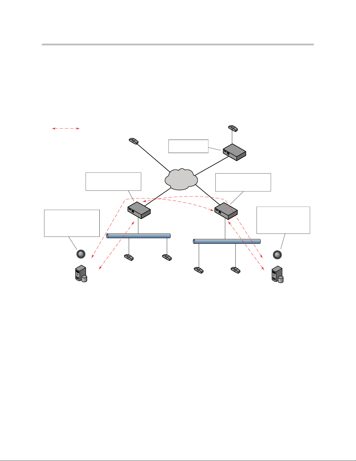
Example 2
In this example, there are two neighbored Path Navigator gatekeepers, one
behind one V2IU, on a private network, and the other behind another V2IU,
on a separate private network.
There is also a codec behind a third V2IU, just as an example. V2IU C is just a
remote V2IU running in the embedded gatekeeper mode.
= Neighboring Gatekeepers
VSX 7000
IP = 90.186.171.200
e164 = 555
not registered to any GK
4300T C
(Use embedded gk)
LAN C
WAN C
Appendix
Viewstation
IP = 10.10.10.10
e164 = 444
gk = 10.10.10.1
10.10.10.10
64.186.171.51
LAN side GK = 192.168.2.80
GK A = 192.168.2.80
Step 1: Setup a Neighbor
With LAN A = 192.168.2.1
Step 2: Setup a Neighbor
With WAN B = 64.10.10.10
Path Navigator
GK A = 192.168.2.80
4300T A
(Use LAN side GK)
WAN A
LAN A 192.168.2.1
PVX 104
192.168.2.104
e164 = 104
Alias = epd
gk = 192.168.2.80
All V2IU’s running VOS Version 5.8.0
PathNavigator running version 7.00.01 (7.00.01.0185)
Cloud
69.52.177.69
PVX 105
192.168.2.105
e164 = 105
Alias = epe
gk = 192.168.2.80
IP
WAN B
PVX 101
192.168.1.101
e164 = 101
Alias = epa
gk = 192.168.1.45
4300T B
(Use LAN side gk)
LAN side GK = 192.168.1.45
64.10.10.10
LAN B
192.168.1.1
PVX 102
192.168.1.102
e164 = 102
Alias = epb
gk = 192.168.1.45
GK B = 192.168.1.45
Step 1: Setup a Neighbor
With LAN B = 192.168.1.1
Step 2: Setup a Neighbor
With WAN A = 69.52.177.69
Path Navigator
GK B = 192.168.1.45
EMV2007
Appendix - 7
Page 92

User Guide V2IU 4300T Converged Network Appliance
V2IU A
1. Setup the Network settings.
a LAN interface IP address = 192.168.2.1
b LAN interface subnet = 255.255.255.0
c WAN interface IP address = 69.52.177.69
d WAN interface subnet = 255.255.255.0
e Default Gateway = 69.52.177.1
2. Setup the VoIP ALG – H323 settings
V2IU A is set to use a LAN side gatekeeper, which is 192.168.2.80
a Gatekeeper Mode = LAN/Subscriber side gatekeeper
b LAN / Subscriber side Gatekeeper Address = 192.168.2.80
Gatekeeper A
1. On the Path Navigator (GK A), setup two Neighboring Gatekeeper
profiles.
(Configuration – Neighboring Gatekeeper – Neighbors – Add)
Note
Note
a In the Add Neighbor Gatekeeper dialog box, add the IP address of the
LAN side V2IU A (192.168.2.1). Click OK.
The reason for setting up the Neighboring statement with the LAN side of the V2IU
A is to enable outbound dialing to standalone endpoints on the public network.
a In the Add Neighbor Gatekeeper dialog box, add the IP address of the
WAN side V2IU B (64.10.10.10). Click OK.
The reason for setting up the Neighboring statement with the WAN side of the V2IU
B is to neighbor with the Path Navigator that is on the LAN side of V2IU B.
Appendix - 8
Page 93

Network Settings
Appendix
Appendix - 9
Page 94
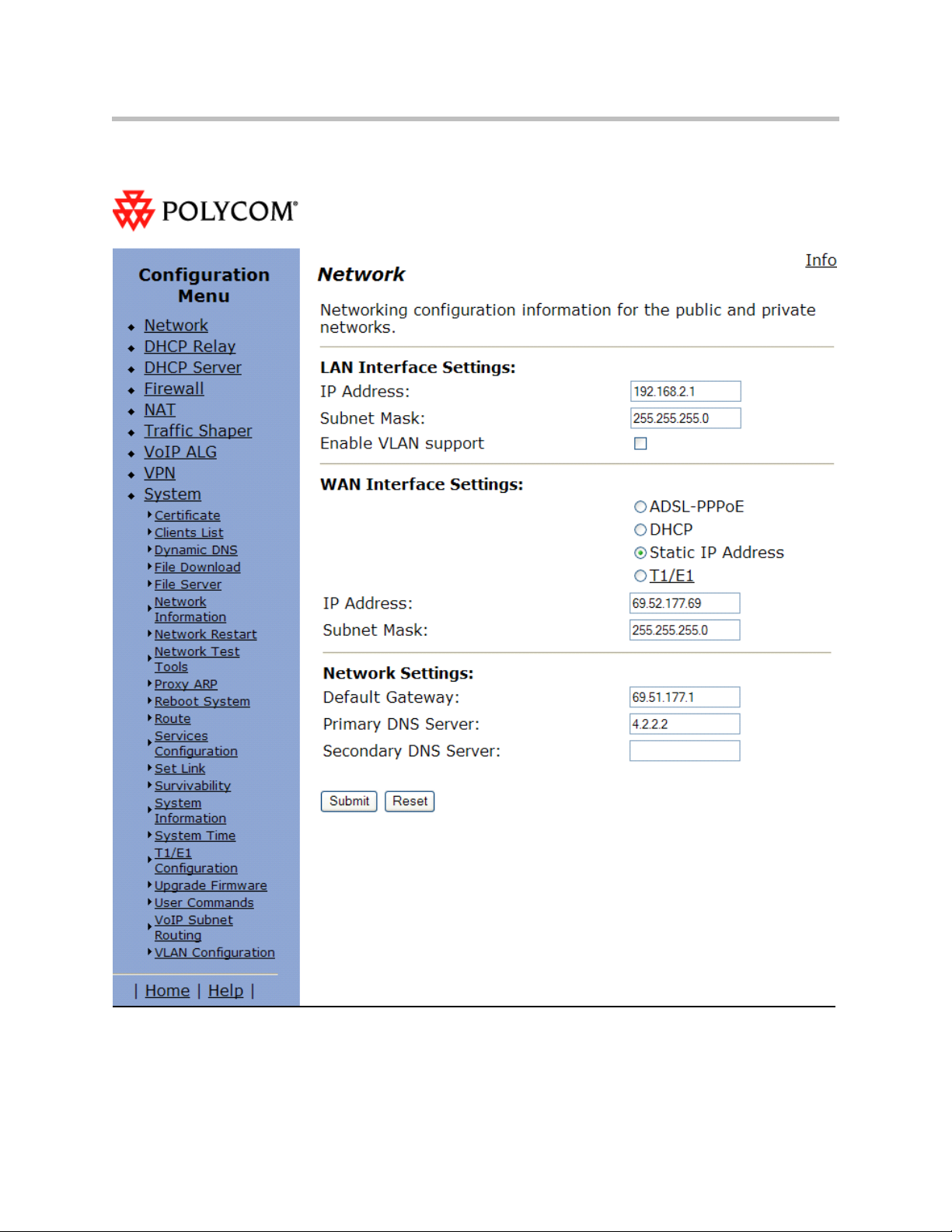
User Guide V2IU 4300T Converged Network Appliance
VoIP ALG – H323 Settings
Appendix - 10
Page 95

Appendix
Appendix - 11
Page 96

User Guide V2IU 4300T Converged Network Appliance
V2IU B
1. Setup the Network settings.
(Configuration -- Neighboring Gatekeeper -- Neighbors -- Add)
a LAN interface IP address = 192.168.1.1
b LAN interface subnet = 255.255.255.0
c WAN interface IP address = 64.10.10.10
d WAN interface subnet = 255.255.255.0
e Default Gateway = 64.10.10.1
2. Setup the VoIP ALG – H323 settings
V2IU B is set to use a LAN side gatekeeper, which is 192.168.1.45.
a Gatekeeper Mode = LAN / subscriber side gatekeeper
b LAN / subscriber side Gatekeeper Address = 192.168.1.45
Gatekeeper B
3. On the Path Navigator (GK B), setup two Neighboring Gatekeeper
profiles.
Note
Note
a In the Add Neighbor Gatekeeper dialog box, add the IP address of the
LAN side V2IU B (192.168.1.1). Click OK.
The reason for setting up the Neighboring statement with the LAN side of the V2IU
B is to enable outbound dialing to standalone endpoints on the public network.
a In the Add Neighbor Gatekeeper dialog box, add the IP address of the
WAN side V2IU A (69.52.177.69). Click OK.
The reason for setting up the Neighboring statement with the WAN side of the V2IU
A is to neighbor with the Path Navigator that is on the LAN side of V2IU A.
Appendix - 12
Page 97

Network Settings
Appendix
Appendix - 13
Page 98
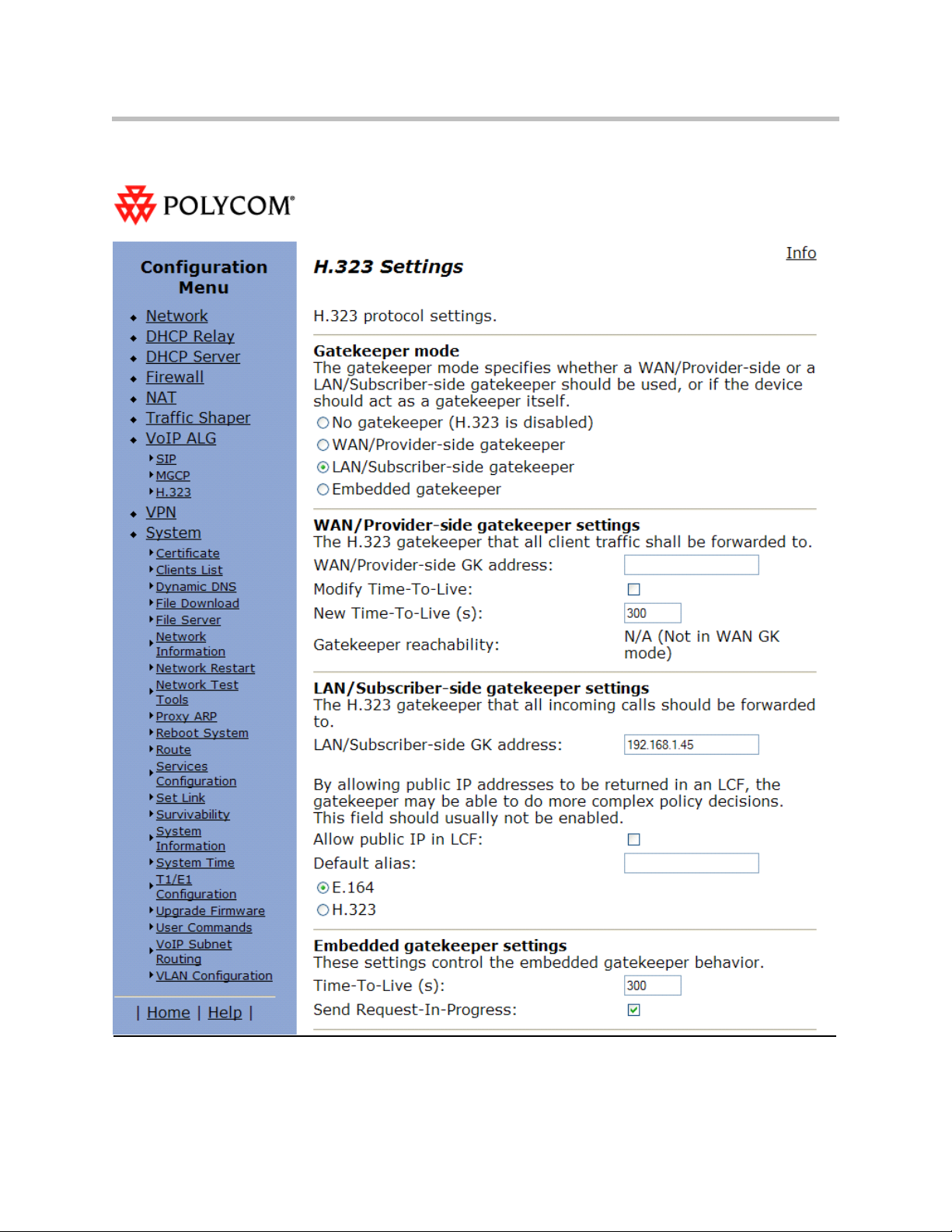
User Guide V2IU 4300T Converged Network Appliance
VoIP ALG – H323 settings
Appendix - 14
Page 99

Appendix
Appendix - 15
Page 100
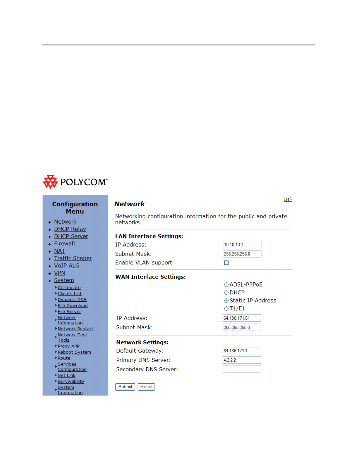
User Guide V2IU 4300T Converged Network Appliance
V2IU C
1. Setup the Network settings.
a LAN interface IP address = 10.10.10.1
b LAN interface subnet = 255.255.255.0
c WAN interface IP address = 64.186.171.51
d WAN interface subnet = 255.255.255.0
e Default Gateway = 64.186.171.1
2. Setup the VoIP ALG – H323 settings
V2IU C is set to use a Embedded gatekeeper.
Network Settings
Appendix - 16
 Loading...