

Page 1
Polycom
®
RSS
User Guide
™
4000 System
5.0.0 | Oct. 2009 | 3150-30828-001
Page 2

Trademark Information
Polycom®, the Polycom “Triangles” logo, and the names and marks associated with Polycom’s products are
trademarks and/or service marks of Polycom, Inc., and are registered and/or common-law marks in the United
States and various other countries.
All other trademarks are the property of their respective owners.
Patent Information
The accompanying product is protected by one or more U.S. and foreign patents and/or pending patent
applications held by Polycom, Inc.
© 2009 Polycom, Inc. All rights reserved.
Polycom, Inc.
4750 Willow Road
Pleasanton, CA 94588-2708
USA
No part of this document may be reproduced or transmitted in any form or by any means, electronic or
mechanical, for any purpose, without the express written permission of Polycom, Inc. Under the law,
reproducing includes translating into another language or format.
As between the parties, Polycom, Inc., retains title to and ownership of all proprietary rights with respect to the
software contained within its products. The software is protected by United States copyright laws and
international treaty provision. Therefore, you must treat the software like any other copyrighted material (e.g.,
a book or sound recording).
Every effort has been made to ensure that the information in this manual is accurate. Polycom, Inc., is not
responsible for printing or clerical errors. Information in this document is subject to change without notice.
Page 3

Table of Contents
Preface····························································································· I
Polycom® RSS™ 4000 Installation and Preliminary
Configuration·············································································· 1-1
General Safety Precautions·················································· 1-1
Preparations····································································· 1-1
Unpacking and Installing the Polycom® RSS™ 4000················· 1-2
Initial Polycom® RSS™ 4000 IP Configuration ························ 1-2
Web User Interface (UI) ······························································ 2-1
Logging into Polycom® RSS™ 4000 via the Web······················ 2-2
Polycom® RSS™ 4000 Web UI Main screen ···························· 2-3
System Information ··························································· 2-3
Product Information ······················································ 2-3
System Usage ······························································· 2-5
Product Activation ························································ 2-6
System Configuration························································· 2-8
IP Address Settings························································ 2-8
Gatekeeper Settings ······················································· 2-9
User Customization ······················································2-10
Archives Backup/Delete················································ 2-13
System Settings····························································2-14
Logger Settings ···························································· 2-16
Upgrade/Reset System ·················································2-18
SSL Configuration ························································2-19
Account Management ·······················································2-21
Endpoint Management··················································2-21
User Management ························································2-23
Group Management······················································2-24
1-i
Active Directory Settings ···············································2-26
Recording Settings···························································· 2-27
Single Point Recording Settings·······································2-28
Point-to-point Recording Settings ····································2-30
Dial Out and Record Through the Web·····························2-33
Multicast Settings·························································2-34
Streaming Settings····························································2-36
Page 4

Table of Contents
Managing Recording Files··················································2-37
Viewing Archive Properties············································2-38
Looking Up Archives ····················································2-38
Sorting Archives ··························································2-39
Changing Archive Properties·········································· 2-39
Playing Back Archives via the Web ··································2-40
Downloading Archives··················································2-40
E-Mail Link·································································2-41
Deleting Archives·························································2-41
Go to Archive Pages ····················································· 2-42
H.323 Connection Status Display·········································2-42
Onscreen User Interface (UI) – Conference Recording··········· 3-1
Single Point Recording Using an Endpoint Menu (onscreen UI)·· 3-2
Main Menu ·································································· 3-2
Start Recording ····························································· 3-4
Live Streaming ····························································· 3-5
Immediate Recording····················································· 3-5
Archive Name Format···················································· 3-6
Using a Polycom MCU for Single Point Recording ··················· 3-7
Point-to-Point Recording ···················································· 3-7
Entering a Recording Room············································· 3-7
Streaming without Recording ·········································· 3-9
Leaving a Recording Room ············································· 3-9
Onscreen User Interface (UI) – Archive Playback···················· 4-1
Video Viewing Rights ························································ 4-2
Quick Access Codes for Archive Playback ······························ 4-3
Sorting Archives ······························································· 4-4
PIN Codes ······································································· 4-5
Fast Forward/Reverse/Stop················································ 4-6
Choose Language for Endpoint Menu ··································· 4-6
ii
Appendix A – Terminal Setting and User Commands············· 5-1
Hyperterminal Parameters ·················································· 5-1
Logging in ······································································· 5-1
Overview of Commands····················································· 5-2
Appendix B - Polycom RSS Media Tools·································· 6-1
Page 5

Polycom® RSS™ 4000 User Guide
Accessing and Installing Polycom RSS Media Tools·················· 6-2
Uninstalling Polycom RSS Media Tools·································· 6-2
Operating Environment······················································ 6-2
Using Polycom RSS Multicast Player ····································· 6-2
Receiving Multicast Videos ············································· 6-3
Playing Multicast Videos ················································ 6-4
Adjusting Video Window Size ········································· 6-5
Video Statistics ····························································· 6-5
Using Media Converter for Polycom RSS ······························· 6-6
Format conversion························································· 6-6
Starting file conversion··················································· 6-6
Using Polycom® RSS™ 4000 Upload····································6-10
Overview of Interface Areas ···········································6-10
Starting File Upload······················································6-12
Pausing File Upload······················································6-13
Stopping File Upload ····················································6-13
Cancelling File Upload ··················································6-13
Appendix C – Regulatory Notices··········································· 7-14
iii
Page 6
Preface
This User Guide provides system operation and setup information for users
and administrators of the Polycom® RSS™ 4000 system.
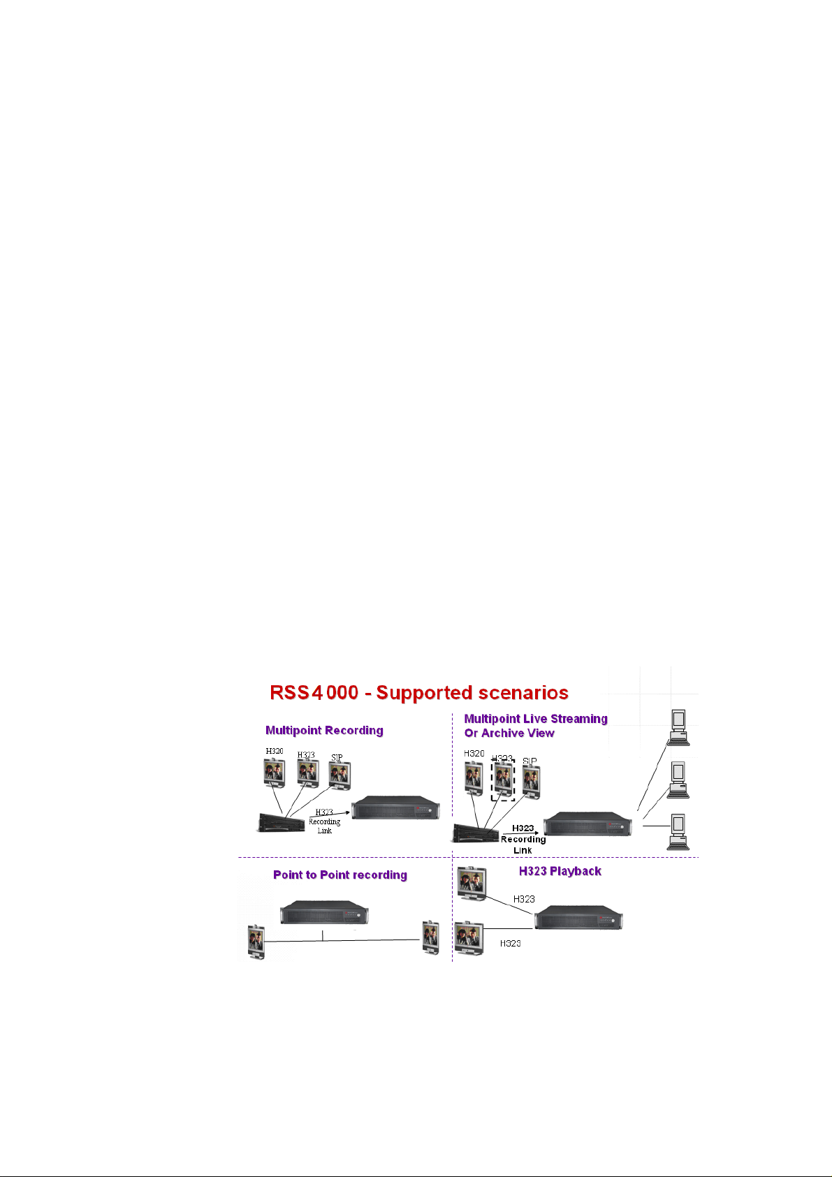
The Polycom® RSS™ 4000 is a network server that enables users to easily
record, stream and archive media content. It supports recording and
archiving of high-definition video content, processing of streaming media,
and H.323 playback. It is an important component of Polycom's peer-to-peer
video communications product series.
The Polycom® RSS™ 4000 can be fully integrated with other Polycom
products (Such as the Polycom RMX 2000 and Polycom HDXs), and is
compatible with devices supporting the H.323 standard. Polycom® RSS™
4000 uses easily remembered DTMF commands and Far End Camera
Controls to start, stop, and pause recording, employ many other recording
options, and perform H.323 playback. The device can produce superior
recordings of multimedia conferences (as high as HD 30 frame/second under
the H.264 standard) using synchronous sound, images, and content
(point-to-point and point-to-multipoint), and transmit them to global
audiences via the Internet for real-time viewing or replay. This server can
store up to 700 hours of storage at 768kbps of H.323 video, audio and
content , and can use common media players such as Windows Media Player
and RealPlayer. Moreover, The Polycom® RSS™ 4000 Supports up to 200
Unicast streams in one single system.
The Polycom® RSS™ 4000 also offers full-strength security functions. It
supports SSL certification and encryption in order to protect the security of
information transmitted from the web, allows the setting of recording and
viewing access rights, and can identify individual video endpoints or
network users.
Page 7

Polycom® RSS™ 4000 Installation and Preliminary Configuration
General Safety Precautions
Follow these rules to ensure general safety:
Keep the area around the Polycom® RSS™ 4000 unit clean, free of clutter
and well ventilated.
1
Decide on a suitable location for the Polycom® RSS™ 4000 rack that will
hold the Polycom® RSS™ 4000 unit and is near a grounded power
outlet.
Use a regulating uninterruptible power supply (UPS) to protect the
Polycom® RSS™ 4000 unit from power surges and voltage spikes, and to
keep it operating in case of a power failure.
Table 1-1 Polycom® RSS™ 4000 Hardware Specification
Hardware Specification
Intel Xeon 2.33GHzx2, 4GB RAM, 500Gx2 Hard disk
(Disk 1: 500GB / Disk 2 (for mirroring): 500GB).
Form Factor: 2U 19”
Height: (89 mm)
Width: (441 mm)
Depth: (485 mm)
Gross Weight: (19.5 kg)
Power Supply: 700W ATX AC power supply w/PFC, 1+ 1 Redundant Power Supply
AC Voltage : 100 - 240 VAC, 60-50 Hz, 10-4 Amps
Window XP EK
Preparations
Obtain the following information from your network administrator:
Polycom® RSS™ 4000 unit, Subnet Mask and Default Gateway IP
Gatekeeper IP address, Prefix, and E.164 of the Polycom® RSS™ 4000.
addresses.
1-1
Page 8
Chapter 1-
Polycom® RSS™ 4000 Installation and Preliminary Configuration
Unpacking and Installing the Polycom® RSS™ 4000
1 Place the Polycom® RSS™ 4000 unit on a stable flat surface in the
selected location, not for rack mount.
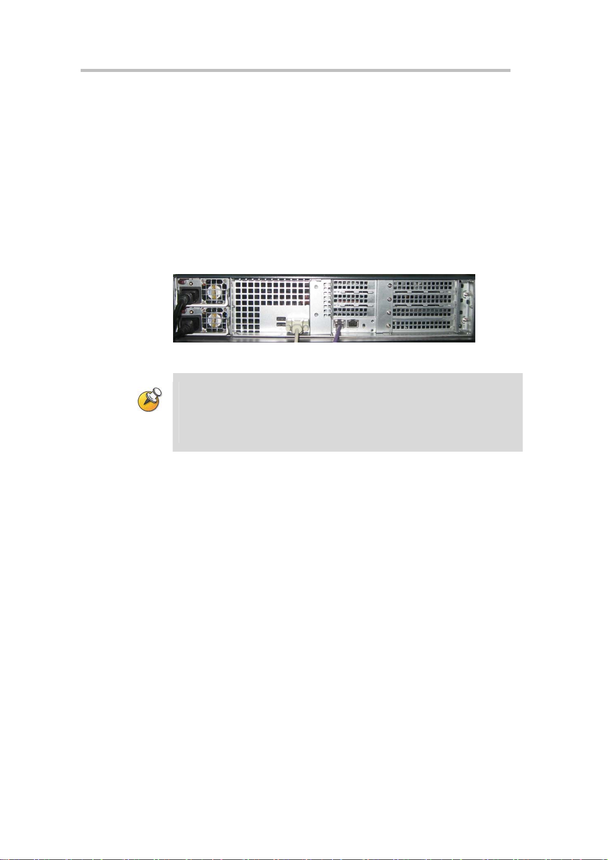
2 Insert each power cord connector into the rear of the unit and connect
each to an appropriately rated socket outlet. The Polycom® RSS™ 4000
unit is supplied with two power cords, BOTH power cords should be
connected to the mains power supply during normal operation.
3 Connect the LAN cable to LAN 1 port on the rear panel of the Polycom®
RSS™ 4000 unit.
4 Turn on power switch.
Figure 1-2 Connecting cables
Plug Acts as Disconnect Device:
The socket outlets to which this apparatus is connected must be installed near the
equipment and must always be readily accessible.
In order to fully isolate the equipment then both power cords should be
disconnected otherwise the system will re main en ergi zed.
Initial Polycom® RSS™ 4000 IP Configuration
The system is shipped with a default IP address:
IP Address: 192.168.1.254
1-2
Subnet Mask: 255.255.255.0
Gateway: 192.168.1.1
There are two ways to change the initial IP address of the system:
Via a cross over LAN cable
Via a RS232 or Telnet Console.
Changing the initial IP address via a cross over LAN cable
1 Connect a cross over LAN cable to LAN 1 port on the rear panel of the
Polycom® RSS™ 4000 unit..
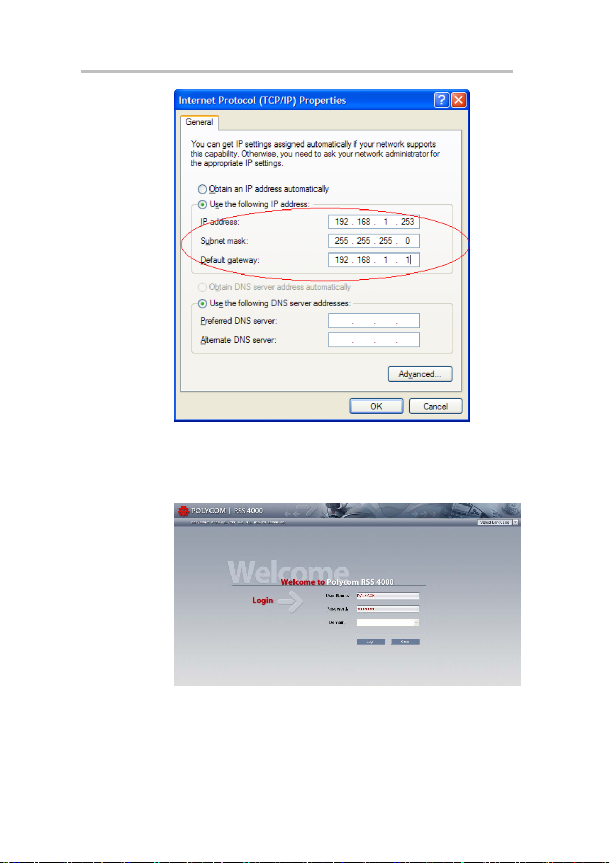
2 Configure your PC to the same segment of the Polycom® RSS™ 4000.
For example, set the IP address as that shown below:
Page 9
Polycom® RSS™ 4000 User Guide
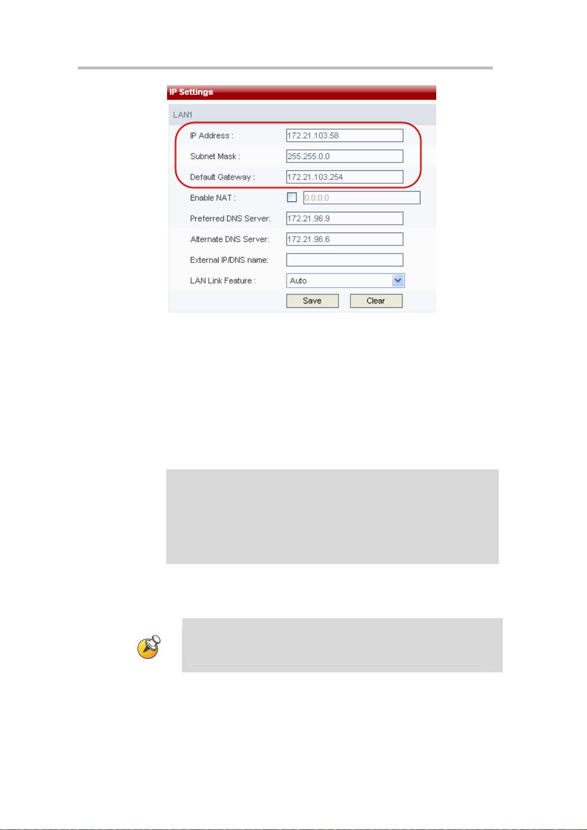
Figure 1-3 IP Address Settings
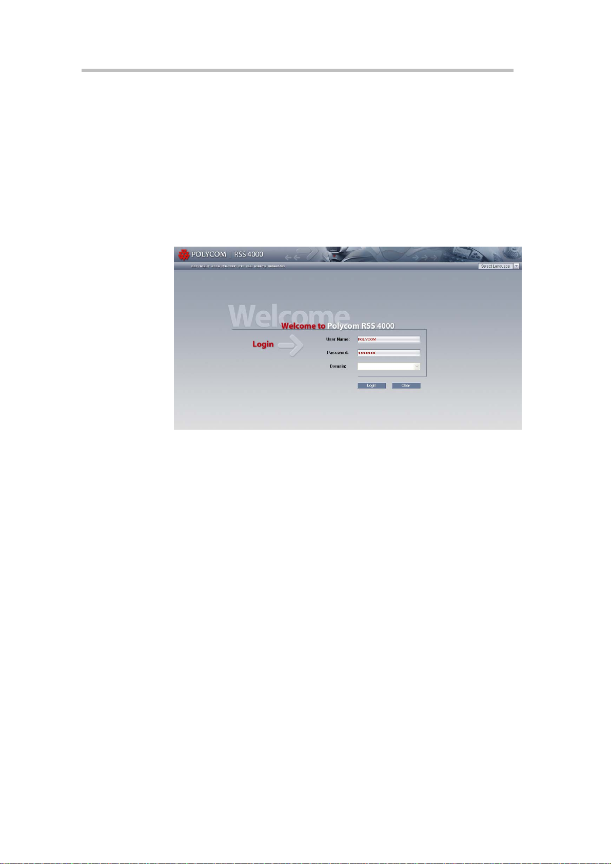
3 Open the internet explorer and browse to: http://192.168.1.254
4 Login to the system. Use the default User name (POLYCOM) and
Password (POLYCOM).
Figure 1-4 Login to Web UI
5 Go to system configuration->IP setting and set a static IP address. Click
the save button and then reset the system.
1-3
Page 10
Chapter 1-
Polycom® RSS™ 4000 Installation and Preliminary Configuration
Figure 1-5 IP Settings Page
Changing the initial IP address via an RS232 Console or Telnet
Another option to modify the IP address of the Polycom® RSS™ 4000 is
using the RS232 console.
1 Connect to the RS232 port – and activate the console (9600, 8bits).
2 When login to the console, input the default password “POLYCOM” to
enter the system.
3 After the user have logged onto the system, enter "?" or "help" after the
"#" to show the following information:
#?
Available commands:
show Show system information.
...
set lan1 static <ip address> netmask <ip mask> [gw <gateway
address>]
4 Change the IP address using the command in below format (the exact
addresses are just for a instance):
set lan1 static 172.21.100.20 netmask 255.255.224.0 [gw 172.21.96.254]
The same steps apply also fo r Telnet connection.
Only one console can be connected at any given time (e ither Telnet or
RS232 not both).
1-4
The system is now ready for use, the following chapters will give further
descriptions for device configuration and operation.
Page 11

Web User Interface (UI)
The Polycom® RSS™ 4000 provides two types of user interface:
Web UI - Web Interface to configure, control, monitor Polycom® RSS™
4000 and view archives.
The following operations can be performed using the Web UI: querying
system information, activation/upgrading, registering to a gatekeeper,
performing customization, backup/deletion of recording files,
configuration of clusters, configuration of multicast videos, configuration
of SSL certificates, setting of single point recording and point-to-point
recording parameters, account management, management of recorded
files, dial-out and record sessions initiated from the RSS, and more. This
chapter provides a detailed explanation of Web management and
configuration.
2
Onscreen UI - User menu which displayed when connecting to the RSS
via the H323 Endpoint (Or MCU), the onscreen UI allows the user to
perform recording and playback tasks. The following two chapters will
explain how to use the onscreen UI to perform recording and playback.
A user's PC must satisfy the following conditions in order to successfully work with
the Polycom® RSS™ 4000's Web U I and play video files:
Must use Windows 2000 SP4, Windows XP SP2, Windows 2003 or Windows
Vista operating systems.
Video player clients are Windows Media player 9 .0 (o r above) or Real Play er or
Polycom proprietary if using multicast.
2-1
Page 12
Chapter 2 -
Web User Interface (UI)
Logging into Polycom® RSS™ 4000 via the Web
1 Enter the Polycom® RSS™ 4000's IP address in the address field and
press enter. The user will see the Polycom® RSS™ 4000's login page, as
shown in Figure 2-1.
2 After cor
press enter to log in. The default user name is "POLYCOM" and the
default password is "POLYCOM". These defaults are pre-set for use in
first-time log in. Pressing the Clear button will clear the entered user
name and password, allowing new values to be entered.
Figure 2-1 Polycom® RSS™ 4000 login screen
If the Polycom® RSS™ 4000 you are logging into is integrated with an LDAP
Active Directory server, users can also enter an Active Directory domain user
name and password in the login screen. In this case, the "Domain" menu in
Figure 2-1 will be enabled. Enter a correct user name and password, and
select the
click the "Login" button or press enter to log in. Please refer to the Active
irectory settings section for detailed information
d
servers.
rectly entering a user name and password in the login screen,
appropriate domain name from the "Domain" pull-down menu;
concerning Active Directory
2-2
Page 13
Polycom® RSS™ 4000 User Guide
Polycom® RSS™ 4000 Web UI Main screen
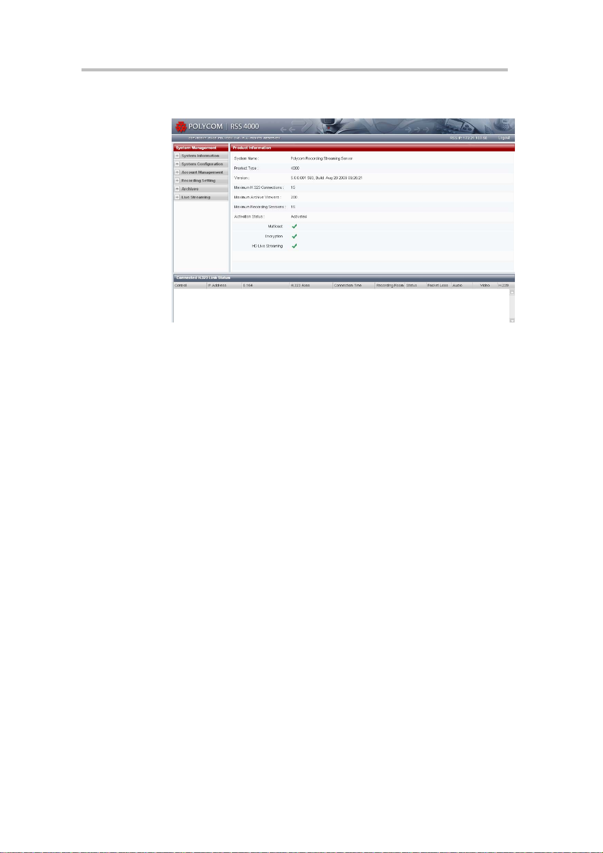
Figure 2-2 Polycom® RSS™ 4000 Web UI Main screen
The Polycom® RSS™ 4000 Main screen includes three major sections:
1 System Management – This section includes the following sections:
System Information, System Configuration, Account Management,
Recording Setting, Archives and Live Streaming.
2 Monitoring – The right section to the System management, the
information in this window will be changed based on the menu
selection in the system management.
3 Connected H.323 Link Status – Monitor and control area for the H.323
devices which connected to the Polycom® RSS™ 4000 at any given time.
System Information
After logging in to Web page, the default view will display the "Product
Information". This page displays product information, system usage, and
activation status.
Product Information
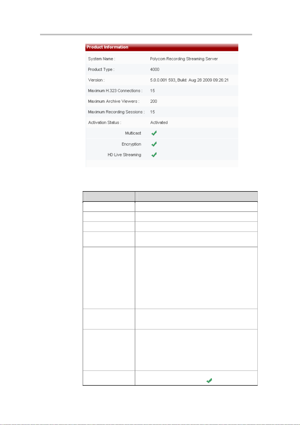
Click on "Product Information" to view the Polycom® RSS™ 4000's system
name, product type, version, maximum H.323 connections, maximum
archive viewers, maximum recording sessions, and activation status, as
shown below.
2-3
Page 14
Chapter 2 -
Web User Interface (UI)
Figure 2-3 Product Information Page
Table 2-1 Product Information Details
Item Details
System name Displays the current Polycom® RSS™ 4000 device name.
Product type Displays the video server type.
Version Displays the current version and distribution date.
Maximum H.323
Connections
Maximum Archive
viewers
Maximum Recording
Sessions
Displays that the Polycom® RSS™ 4000 can support a
maximum of 15 H.323 playback connections.
Displays that the Polycom® RSS™ 4000 can support a
maximum of 200 users simultaneously connected to Web
UI to play videos.
If the playback was recorded at the rate of :
[128k ~ 1024k] – It supports 200 simultaneous archived
playbacks;
(1024k ~ 2048k] – It supports 100 simultaneous archived
playbacks;
(2048k ~ 4096k] – It supports 50 simultaneous archived
playbacks.
Displays that the Polycom® RSS™ 4000 can support
simultaneous recording by 15 endpoints. This implies that
it can support 15 single-point recording sessions.
2-4
Activation Status
Multicast
Displays whether the Polycom® RSS™ 4000 has been
activated. This field will show "Not activated" when the
device has not been activated after a software upgrade,
and will otherwise show "Activated". Only an activated
Polycom® RSS™ 4000 can perform normal recording.
Please refer to the Product activation section for detailed
informati
Displays whether the multicast function is activated. When
the multicast module is activated
on concerning activation.
is displayed.
Page 15
Item Details
Configure multicast parameters in the "Recording
parameters-> multicast settings" page. See multicast
settings for details. When not activated, is displayed.
To use the multicast function, acquire a multicast-activated
product key code. Steps for activating the multicast
function are the same as those for new device activation.
Please refer to the Product activation section for further
information.
Displays whether the AES encryption function is activated.
When the encryption function is activated,
Encryption
HD Live Streaming
displayed here, otherwise
information about AES encryption, please refer to the
System Settings.
Displays whether the 720p live streaming function is
activated. After activating the device can live stream at
720p resolution.
Note: 720p 50/60 fps is not yet supported.
Polycom® RSS™ 4000 User Guide
will be
will be displayed. For more
System Usage
The supported number of “Maximum H.323 Connections”, “Maximum
Archive viewers” and “Maximum Recording Sessions” depends on the
license you bought. Please consult your vendor for det ail info rma tion.
Before using the “Multicast” “Encryption” and “HD Live Streaming”
functions, you need to buy corresponding license and active the device.
Please consult your vendor for detail info rmation.
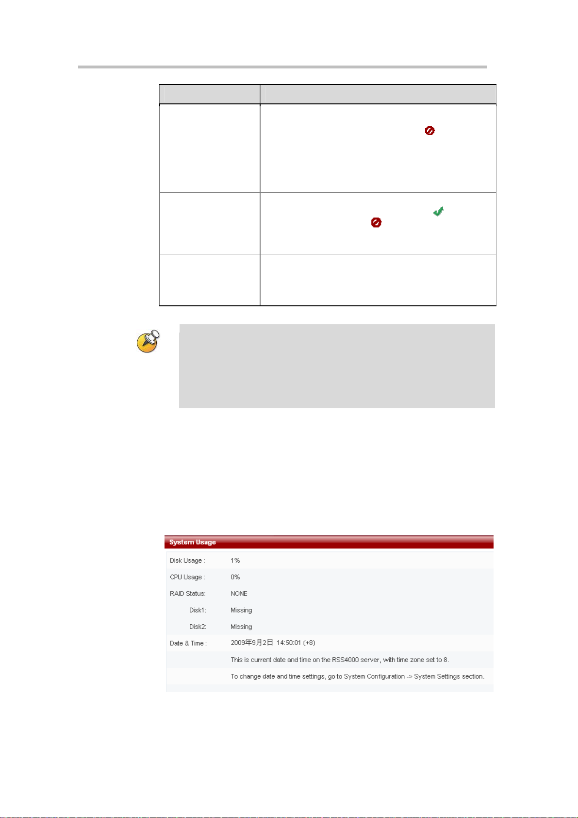
Click on "System Usage" in the navigation bar on the left side of the screen to
view the Polycom® RSS™ 4000's current hard drive usage, CPU usage,
current device time, and synchronization of device time and time on current
computer.
There are 2 hard disk on Polycom® RSS™ 4000. The RAID is configured as
RAID-1 (mirroring). The two hard disks have identical data on them. Data
written to one disk will automatically be duplicated to the other one.
Figure 2-4 System Usage Page
2-5
Page 16
Chapter 2 -
Web User Interface (UI)
Table 2-2 System Usage Details
Item Details
Hard drive usage
Displays the Polycom® RSS™ 4000's current hard drive
resource usage.
CPU usage Displays the Polycom® RSS™ 4000's current CPU usage.
Display the status of RAID:
NONE
– the RAID is not available;
Optimal
Degraded
Rebuild
Build / Verify
Verify
– the RAID is working fine;
– there is something wrong with the RAID;
– the RAID is rebuilding data;
– the RAID is building or V erifying dat a ;
– the RAID is verifying data.
RAID Status
Display the status of hard drive:
Disk1
Disk2
Date & time
Online
– the hard drive is available;
Missing
Rebuilding
– the hard drive can not be detected;
– the hard drive is rebuilding data.
Displays the Polycom® RSS™ 4000's current date and
time.
This screen is automatically refreshed once in every 30 seconds.
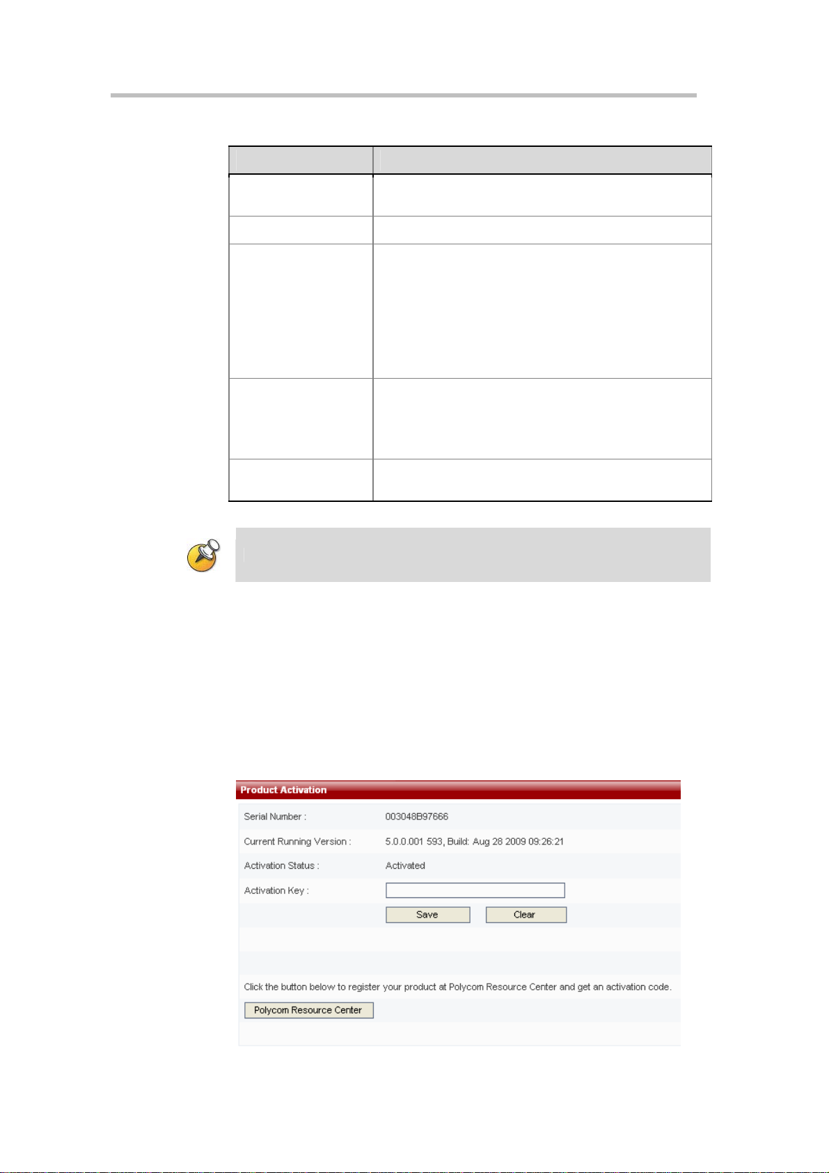
Product Activation
The user must activate a Polycom® RSS™ 4000 after purchase or software
upgrade before the user can perform normal recording.
To activate your device
1 Log into the web interface of Polycom® RSS™ 4000, and go to System
Information > Product Activation.
2-6
Page 17
Polycom® RSS™ 4000 User Guide
Figure 2-5 Product Activation
2 Click on “Polycom Resource Center” to enter the Polycom Resource
login page.
3 Sign in with your registered email account and password. If you are a
new user, register for an account first.
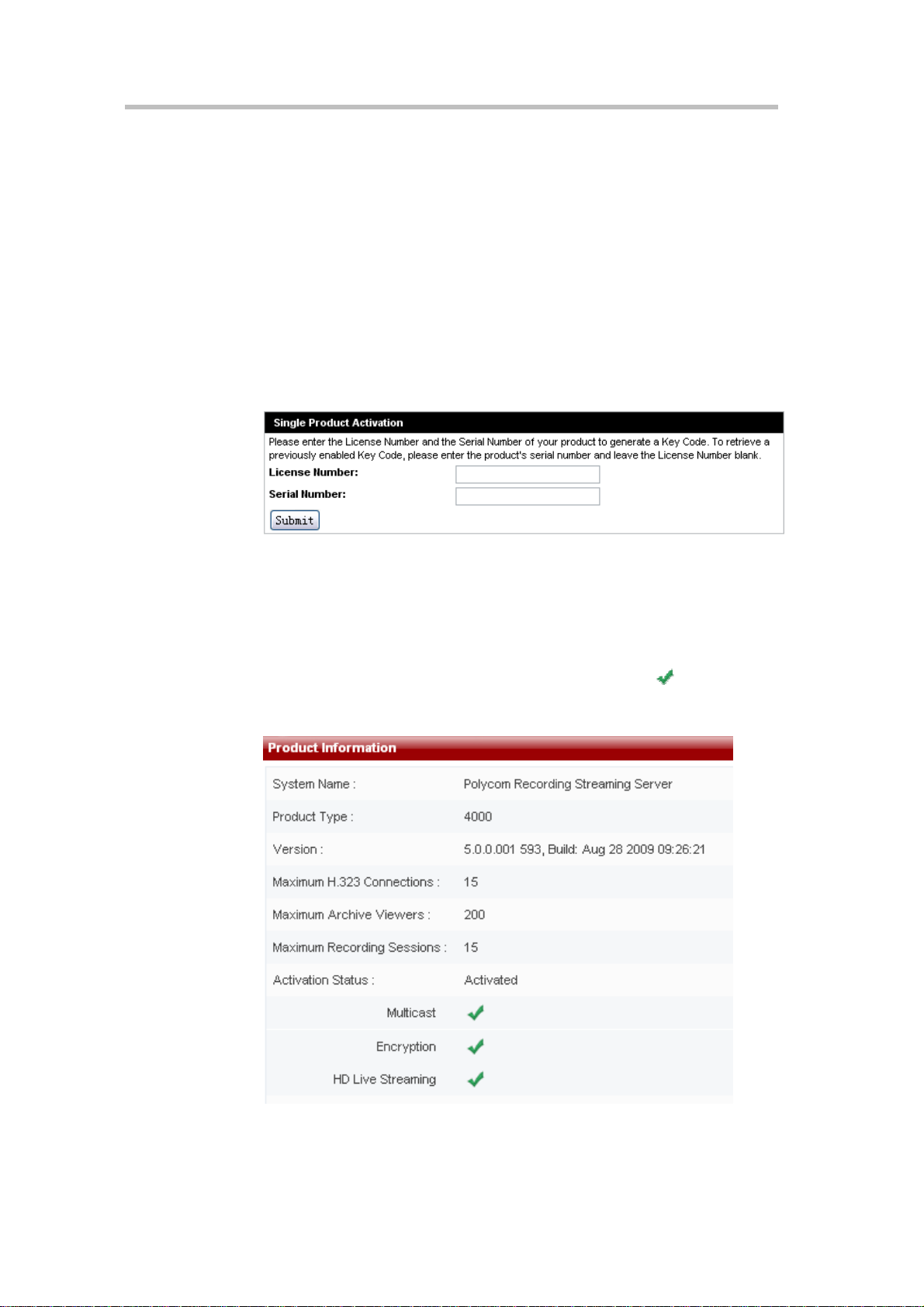
4 Go to Service & Support–> Product Activation -> Single Product
Activation.
5 Input the License Number and the Serial Number and click Submit to
generate the Key Code.
You can get the License Number and the Serial Number from the printed
document shipped with your device.
Figure 2-6 Single Product Activation
6 Enter the generated Key Code in the field shown in Figure 2-5 and click
Save.
Following successful activation, the "Activation status" property in Product
Information page will display "Activated". If you also purchase the multicast
function, AES function or HD live streaming function, a
will appear in
the "Multicast" , "Encryption" or “HD Live Streaming” properties sections, as
shown below.
Figure 2-7 The device has been activated successfully
2-7
Page 18
Chapter 2 -
Web User Interface (UI)
If you wish to activate the device's optional functions alone, you must first obtain a
product license with thes e functi ons. Pleas e contact a distri butor if you wish to obtain
such a license.
Please do the activation in the following order: s ystem license (5, 1 0, or 15); then HD
Live Streaming; then multicast; then encryption.
System Configuration
Click on "System Configuration" in the navigation bar on the left side of the
screen. This page can be used to perform basic configuration tasks, including
IP settings, gatekeeper settings, user customization, backup/delete settings,
system settings, logger settings, upgrade/reset system settings, and SSL
encryption certificate configuration.
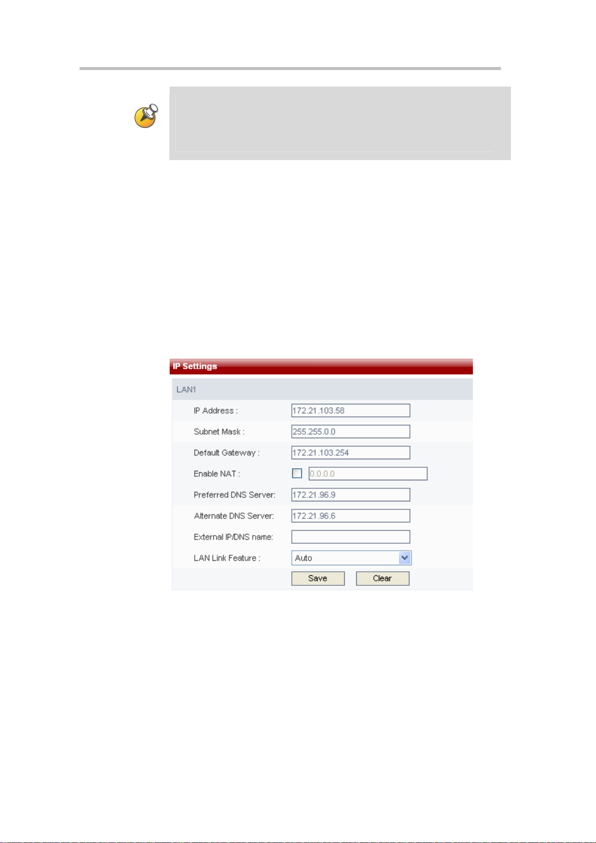
IP Address Settings
Click on "System Configuration" -> "IP Settings" in the navigation bar to
enter the IP settings page. The LAN1 IP address, subnet mask, gateway, and
DNS server can be set using this page.
2-8
Figure 2-8 IP settings page
The device's IP address, subnet mask, default gateway, and DNS server
address can be set manually on this page. A maximum of two DNS servers
can be set. After completing settings, click on the "Save" button to save the IP
address and DNS server address, and a dialog box will appear to remind the
user that the system required to be restarted in order for the new settings to
take effect. After restart, the new IP address must be used to visit the Web UI
to perform management.
Network Address Translation (NAT) network environments use private
internal IP addresses for devices within the network, while using external IP
addresses to allow devices on the LAN to communicate with other devices
outside the LAN. If your Polycom® RSS™ 4000 is connected to a LAN that
Page 19
uses a NAT, you can enable NAT option to allow the Polycom® RSS™ 4000
to communicate with external networks. If “Enable NAT” is selected, the
external address for NAT usage must be configured. The calling party
outside the LAN will call the NAT address of your system, while local users
on your LAN will continue to use the LAN address.
When setting the IP address, only dots and numbers within the scope of
0-255 can be entered for the IP address, subnet mask and gateway address.
Please check that an entered address is valid, otherwise an error message box
will pop up.
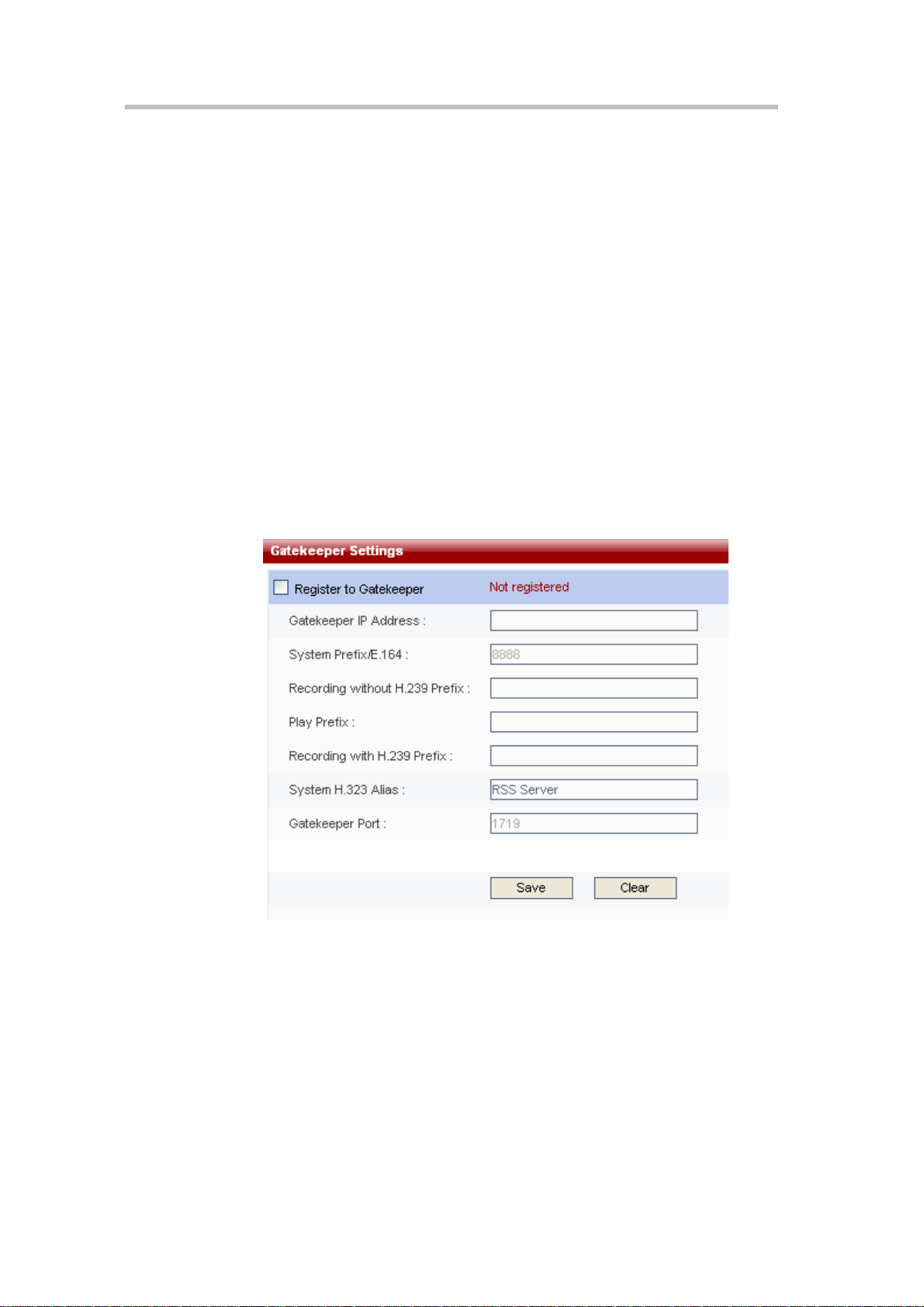
Gatekeeper Settings
Click on "System Configuration" -> "Gatekeeper settings" in the navigation
bar to enter the gatekeeper settings page. This page is used to configure
whether the device registers to a gatekeeper. After registering to a gatekeeper,
endpoints may call the Polycom® RSS™ 4000's E.164 alias to establish a
connection, and there will be no need to use a cumbersome IP address.
Gatekeeper configuration items will be enabled when this box is checked.
Then set the parameters. The word "Registered" will appear next to the check
box after successfully registering to a GK.
Polycom® RSS™ 4000 User Guide
Figure 2-9 Gatekeeper setting page
If the device is registered to a gatekeeper, endpoints will be able to quickly
access the Polycom® RSS™ 4000's Onscreen UI record or playback interfaces
using the record and play prefixes registered with the GK.
Furthermore, the Polycom® RSS™ 4000 can also integrate with a gatekeeper,
and take advantage of registration of identical system prefixes to enable
multiple Polycom® RSS™ 4000 devices to share recording resources or H.323
connections. When an endpoint calls an E.164 alias plus a play prefix or
recording prefix to connect with a Polycom® RSS™ 4000 device, the
Polycom® RSS™ 4000 can determine the H.323 connection request type. If
resources are not available, the RSS will send a busy message to the
requesting GK. The GK will in turn send the playback or record request to
2-9
Page 20

Chapter 2 -
Web User Interface (UI)
the next available Polycom® RSS™ 4000 device with the same prefix, and the
user can play back or record a video on another Polycom® RSS™ 4000
without having to disconnect and reconnect.
Table 2-3 Details of Gatekeeper Settings
Item Details
Gatekeeper IP Address
System prefix/E.164
number
Recording without
H.239 Prefix
Play Prefix
Recording with H.239
Prefix
System H.323 Alias
Enters the IP address of the GK the user wishes to register
to.
Sets E.164 alias of the Polycom® RSS™ 4000. After
registering, endpoints may use this E.164 to call the
Polycom® RSS™ 4000. The entered E.164 must have a
numerical value and may not exceed 16 digits in length;
otherwise an error message will pop up.
Sets the recording prefix of the RSS. The user can directly
enter the device's single point recording menu when the
endpoint calls the E.164 alias + recording prefix. The
Polycom® RSS™ 4000 will identify the recording request
on the basis of this prefix.
Sets the play prefix of the RSS. The user can directly enter
the device's video play menu when the endpoint calls the
E.164 alias + the play prefix. The Polycom® RSS™ 4000
will identify the playback request on the basis of this prefix.
Sets the H.239 dual stream recording prefix of the RSS.
The user can directly enter the device's single point record
menu when the endpoint calls the E.164 alias + H.239
prefix. The Polycom® RSS™ 4000 will identify the dual
stream recording request on the basis of this prefix.
Sets the H.323 alias of the Polycom® RSS™ 4000. After
registering, the endpoint will use this H.323 Alias to call the
Polycom® RSS™ 4000. The entered length cannot exceed
16 digits.
Gatekeeper Port
After completing relevant settings, click on "Save" to perform registration.
"Registered" will be displayed if the registration is successful, otherwise "Not
registered" will be shown.
User Customization
The Polycom® RSS™ 4000 permits users to customize the system's IVR voice
messages, Web page logos, login screen welcome message, endpoint menu
background, and endpoint menu language.
Click on "System settings-> User customization" in the navigation bar on the
left side of the screen to enter the customization interface.
2-10
The default value of 1719 typically does not need to be
changed.
Page 21
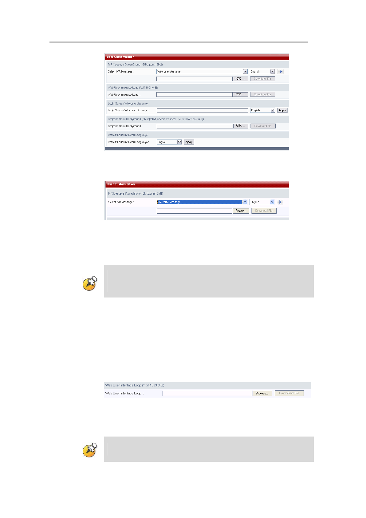
Figure 2-10 User customizati on screen
Customizing the IVR Messages
Polycom® RSS™ 4000 User Guide
Figure 2-11 IVR Message setting section
Users will hear different IVR messages when operating the Polycom® RSS™
4000. The user can change the system's IVR messages in the "IVR message"
area on this interface.
When an IVR file is uploaded to the Polycom® RS S™ 4000, the file name must
consist of only alphanumeric characters.
The file format is PCM, 16 bit, single-channel file with a sa mpling frequen cy of 16KHz.
After changing IVR messages, the user can select the corresponding language
and click on the play button to the right to listen。
If the user wish to change the IVR messages, first select the corresponding
language, and then click on the "Browse" button beneath the drop-down list.
Confirm the path of the file to be changed, and click on the "Download file"
button to download the new file. After the file has been downloaded, play
the message to confirm that the file change has been successful.
Customizing Web user interface logos
Figure 2-12 Web user interface logo setting section
The user can change Web interface logos in the "Web user interface logo"
area of the interface.
Logo image files must have file names consisting only of alphan umeric characters;the
file format must be GIF and file size must be 1003 × 46.
2-11
Page 22
Chapter 2 -
Web User Interface (UI)
Click on the "Browse" button in this area, confirm the path of the file to be
changed, and click on the "Download file" button to download the new file.
After the file has been downloaded successfully, the system's logos will be
replaced with the new logos.
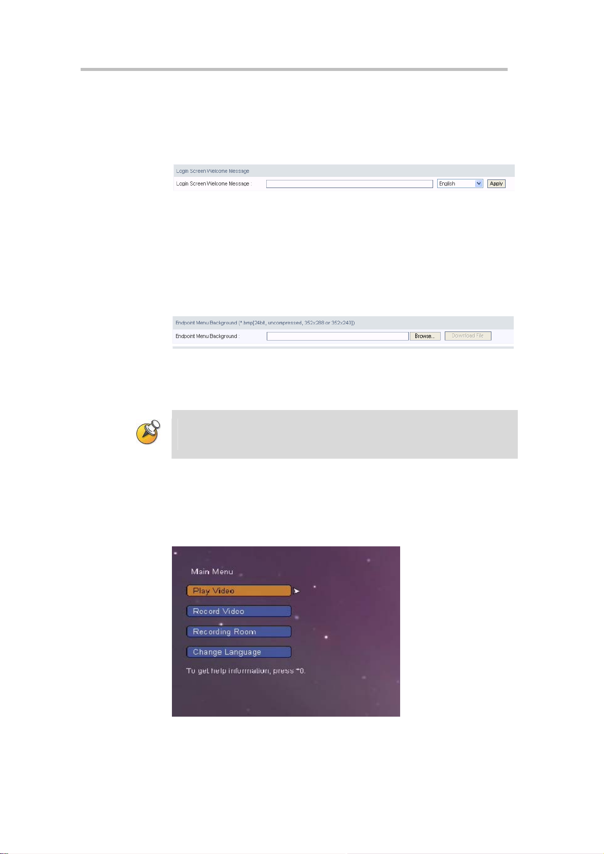
Customizing the login screen welcome message
Figure 2-13 Welcome Message setting section
The user can change the login interface welcome message in the "Login
screen welcome message" area of the interface.
Enter the text of the new welcome message in the "Login screen welcome
message" input box, and select the system software language version. Click
on the "Apply" button to change the Web login screen welcome message.
Customizing the endpoint menu background
Figure 2-14 Endpoint menu background setting section
The user can change the endpoint menu background image in the "Endpoint
menu background" area of the interface.
Endpoint menu background image files must have names consisting only of
alphanumeric characters; images must be in bmp format, and must have a resolution
of SIF (352 × 240) or CIF (352 × 288).
Click on the "Browse" button in this area, confirm the path of the file to be
changed, and click on the "Download file" button to download the new file.
After the file has been downloaded successfully, the endpoint menu
background will be replaced with the downloaded image file, as shown
below.
2-12
Figure 2-15 Endpoint menu after changing the background image
Page 23
Polycom® RSS™ 4000 User Guide
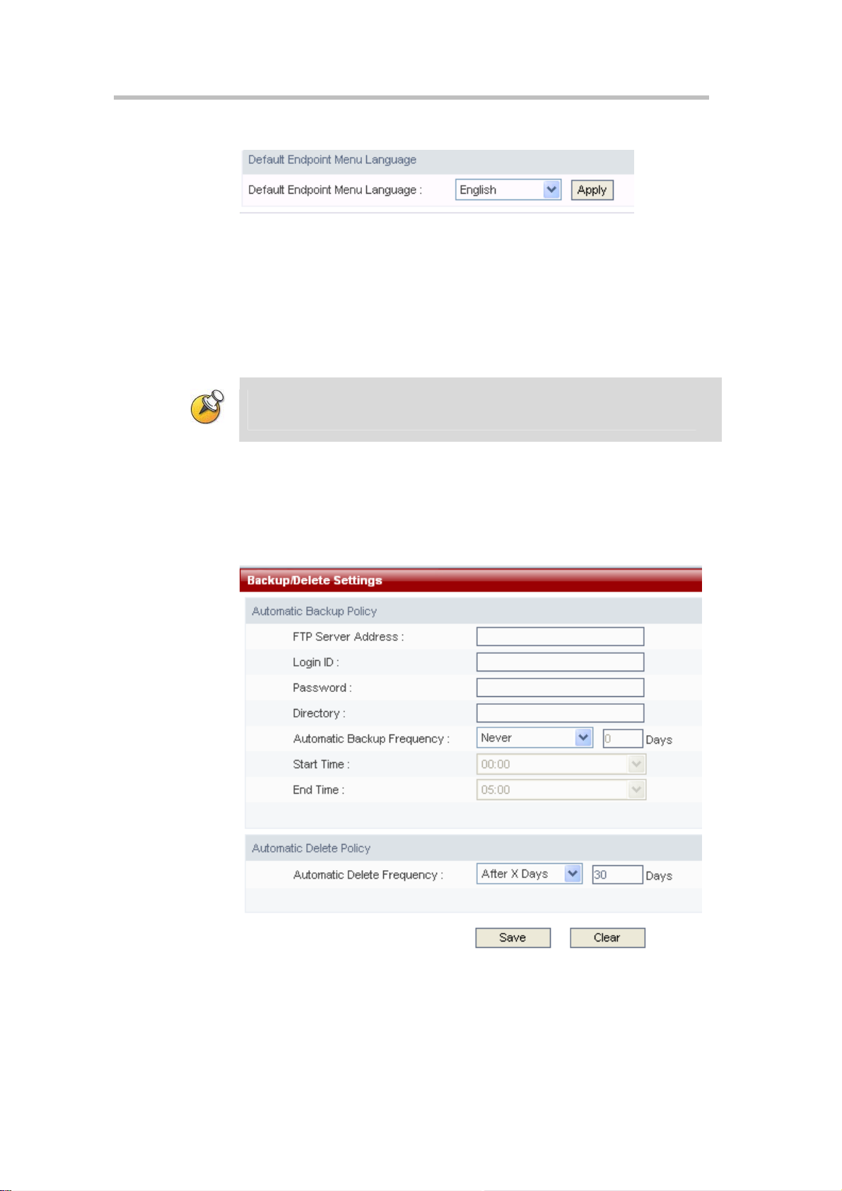
Setting the default endpoint menu language
Figure 2-16 Default endpoint menu language setting section
After the endpoint is used to call and establish a connection with the
Polycom® RSS™ 4000, the menu screen sent from the Polycom® RSS™ 4000
will appear on the endpoint.
The default endpoint menu language can be set using the "default endpoint
menu language" area. Select on the languages and single-click the "Apply"
button to change the endpoint menu language.
Changes to the menu language will take affect on the next H.323 Connection to the
Polycom® RSS™ 4000.
Archives Backup/Delete
Click on "System Configuration -> Backup/Delete Settings" in the navigation
bar to enter the screen shown below. This interface can be used to configure
backup and deletion of recorded video files.
Figure 2-17 Backup/deleterious settings screen
The user should configure a FTP server in where he would like back up the
archives to. The configurations include the FTP Server Address, Login ID,
Password and Directory.
2-13
Page 24

Chapter 2 -
Web User Interface (UI)
Backup Settings Policies
There are three options with regard to automatic backup frequency:
Never backup – Video files will not be backed up to the FTP server if
this is selected.
Backup after end of recording – Video files will be immediately backed
up to the FTP server if this is selected.
Backup after a specified number of days- Video files will be backed up
to the FTP server at a configured frequency if this option is selected. The
backup time must be set. Specify the number of days after recording, and
the backup start time on that day. The number of days may be any value
in the range of 1-999, and any time may be set from 0:00 to 23:00; the
backup end time must be later than the backup start time.
The file names of archives that have been backed up will be displayed in pink in the
archive list.
Deletion Policies
There are three possible deletion policies that can be selected:
Never delete – Video files will be stored indefinitely on the Polycom®
RSS™ 4000's hard drive when this option has been selected.
Delete after backup – Video files will be immediately deleted after being
sent to the backup server when this option has been selected.
Delete after a specified number of days – Sets the number of days after
the end of recording before video file are deleted; the number of days
may be any value in the range of 1-999.
If BOTH “Back after end of recording” and “Delete after backup” are selected,
the system will keep the archives for one day instead of removing it
immediately, for avoiding invisibility of the Archived list.
If "Never Auto Dele te" is enabled on the vi deo file propertie s scree n (ple ase
refer to Changing Archive Properties section), the video file will not be deleted
even if the backup/delete strategy allow s deleti on .
System Settings
2-14
Clicking on "System Configuration -> System Settings" in the navigation bar
on the left side of the screen allows the user to configure items describe in
Table 2-4.
Page 25
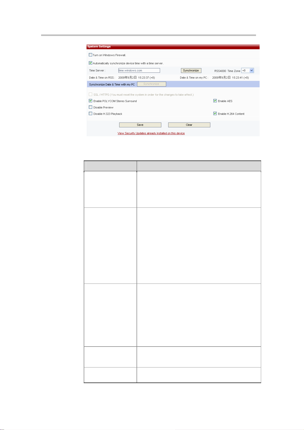
Figure 2-18 System Settings Page
Table 2-4 System Settings Details
Item Details
Turn on or turn off the Polycom® RSS™ 4000 system’s
firewall. When it is enabled, Windows Firewall blocks all
Turn on Windows
Firewall
unsolicited incoming network traffic on all network
connections. Blocking unsolicited incoming traffic makes
the RSS less open to attack and increases its level of
security.
Polycom® RSS™ 4000 User Guide
Automatically
synchronize device
time with a time server
HTTPS/SSL
Enable POLYCOM
Stereo Surround
When checked, the device time will be automatically
synchronized with the set time server. The administrator
must set the location of the time server. Clicking on the
"Synchronize" button will synchronize the device time with
the time server. When unchecked, the Polycom® RSS™
4000’s device time will be synchronized with the time of the
local PC by clicking on the "Synchronize" button.
Time Server – Sets the location of the time server. It can
be a DNS name or an IP address. When setting to a
DNS name, ensure that the configured DNS server is
able to resolve the name.
Time Zone – Sets the time zone for the Polycom®
RSS™ 4000 system time.
Sets whether or not SSL authentication encryption is
activated for communication between the web server and
the users. After changing this setting, the device must be
restarted for the new setting to take effect. If the user
purchased an activation code with security mode and used
it to activate the device, then this item will be disabled. It
will not permit the user to turn off the authentication
function in order to protect secure web communications.
After turning on the authentication encryption, the SSL
certificate on the server must be configured. For more
detailed information, please refer to SSL Configuration.
Selecting this item will enable the Polycom® RSS™ 4000’s
Siren22 stereo recording function. This option is selected
(enabled) by default.
Disable Preview
Selecting this item will disable the playback preview
function in the Onscreen UI.
2-15
Page 26
Chapter 2 -
Web User Interface (UI)
Item Details
Disable H.323
Playback
Enable AES
Enable H.264 Content
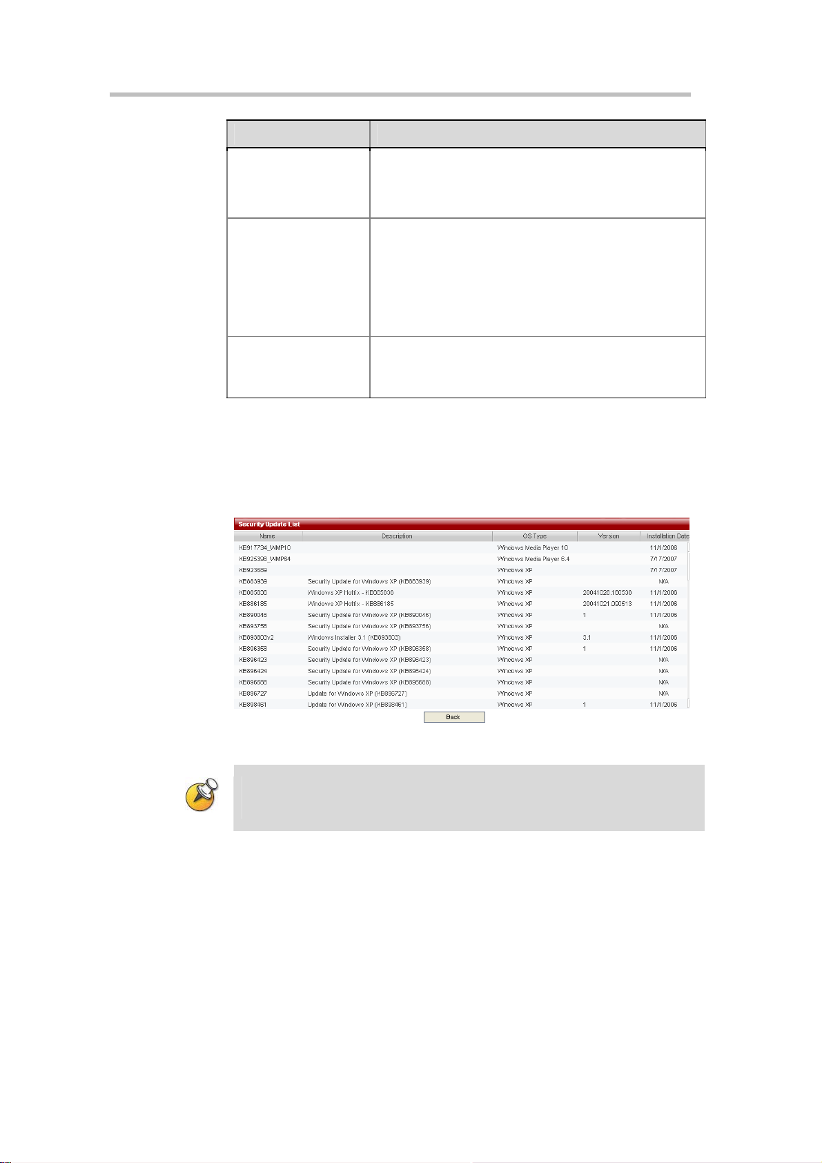
Clicking on the "View Security Updates Already Installed on this Device" link
on the bottom of the page will look up a table of system updates already
installed on the Polycom® RSS™ 4000 device, as shown in below figure.
Clicking the "Back" button on this page will return the user to the previous
System Settings page.
This item is not checked by default. If selected, it will
disable the H.323 connection’s playback function and "Play
Video" will be disabled in the Onscreen UI main menu.
This setting does not affect playback from Web site.
If this function is enabled, the system will automatically
encrypt H.323 calls with other endpoints or MCUs with
AES encryption, if the endpoint or MCU supports AES.
Note:
AES encryption is an optional function of the
Polycom® RSS™ 4000 and will not be available un til a
license is purchased and ac tivated. To obtain this function,
please contact your supplier.
This option is enabled by default.
When checked, the Polycom® RSS™ 4000 will support
H.264 content sending from endpoint.
Logger Settings
2-16
Figure 2-19 Security Updates Table
When synchronizing the device’s system time with an NTP server, the user must set
an active NTP server address. Since the communication between the device and the
NTP server requires a certain time, the system time may not be instan tly upda ted.
Polycom® RSS™ 4000 offers a background log backup function. The log files
are used to troubleshoot the system by the Polycom Certified support
experts.
Clicking on "System Configuration -> Logger Settings" allows the user to
configure the Polycom® RSS™ 4000 system log information, the log models
generated, and the size of the log files. In general it’s recommend not to
modify the default setting of this section, unless instructed by the Polycom
certified support expert.
Page 27
Polycom® RSS™ 4000 User Guide
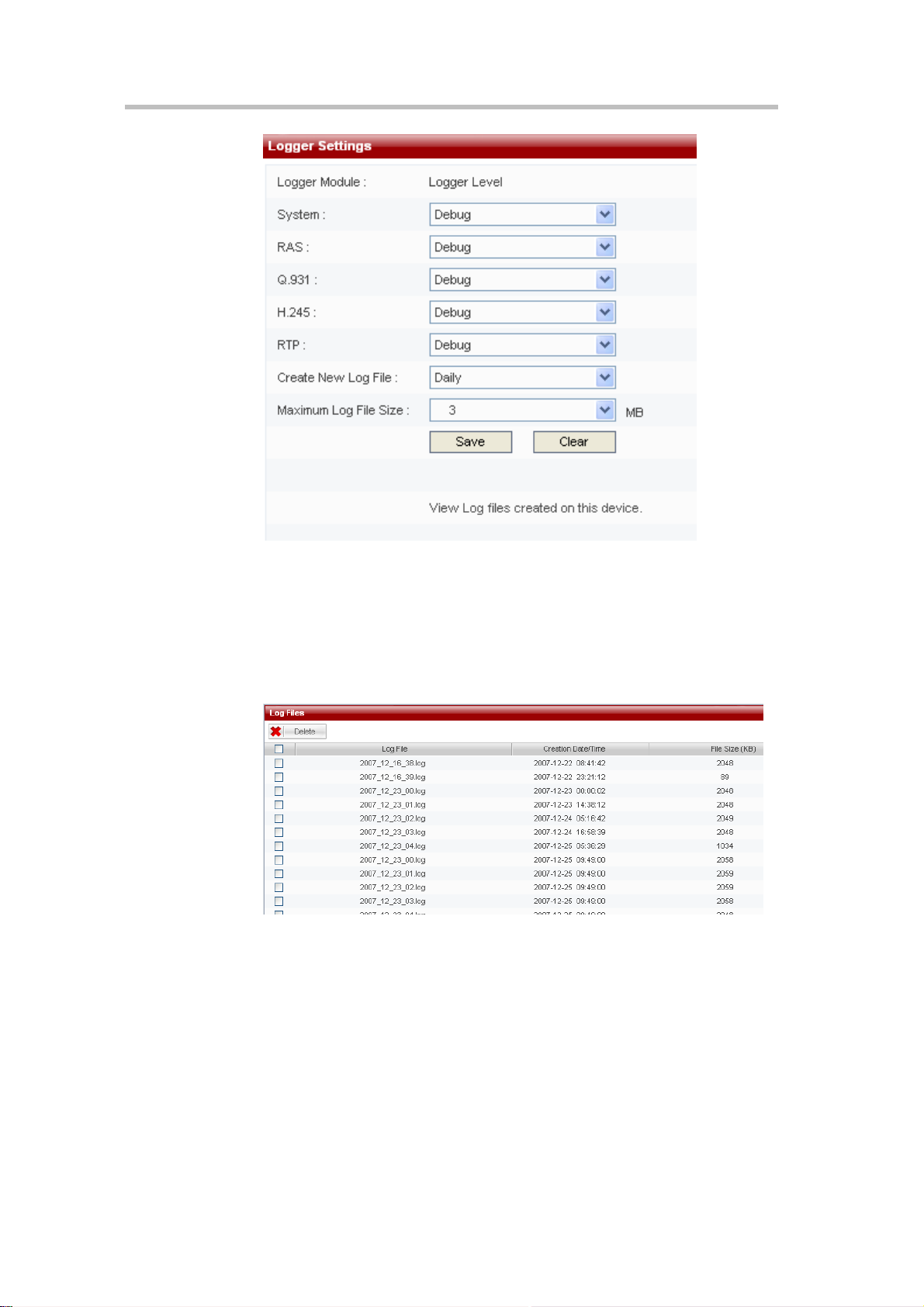
Figure 2-20 Logger Settings Page
Managing Log Files
For log files already created by the device, Polycom® RSS™ 4000 offers a
function to manage these log files. In the page shown above, click on the
"View Log Files Created on this Device" link on the bottom of the page, and
enter the View Log Files Table page, as shown below:
Figure 2-21 Log Files
In this page, the user can view the information and content of log files, and
also download and delete the device’s system log files.
View Log Files:
Single-click the log file name in the table, and the user can view the contents
of the log file. At this time, the system will show the file contents by opening
a new window.
Download Log Files:
Right-click the log file name in the table once, and select "Save Target As". At
this time, a file download message box pops up, and the user can save this
2-17
Page 28

Chapter 2 -
Web User Interface (UI)
log file in his computer’s file destination path.
Delete Log Files:
First select the log file for deletion, the user can select a single file or multiple
files to be deleted. The user can also delete all files. After selecting the files to
be deleted, single click the "Delete" button.
The check box on the left sid e of t he first row i n the l og ta ble i s "Sel ect Al l". Ch eckin g
this check box will result in all log files being selected;
Log files that are in the process of creating cannot be deleted.
Upgrade/Reset System
Clicking on "System Configuration -> Upgrade/Reset Sys tem" in the
navigation bar on the left side of the screen allows the user to upgrade
software. Software upgrade for the Polycom® RSS™ 4000 device requires
having the corresponding upgrade key code for the upgrade package.
Different software upgrade packages have different key codes.
2-18
Figure 2-22 Upgrade/Reset System
To upgrade the system software version, click the License Agreement link in
the Software Download section, if the user agrees with the terms after read
them, choose the checkbox indicated agreement and then the browse button
will be activated for uploading the upgrade file. Click the button and then
choose the local upgrade file, click the Download File button to upgrade the
system software.
After clicking the Download File button to upload the upgrade package, a prompt box
will immediately pop up asking the user to reboot the system. However, the user
should wait for (about 5 minutes) until the upload process is comp leted and then click
the Restart button to reboot the s ystem. If the uploa d is not complete, a warning box
will pop up and will no t al low reboot..
After the software has been successfully upgraded, the device’s software
version should be the same as the software version of the upgrade package.
Page 29

Polycom® RSS™ 4000 User Guide
If the software version information did not change, it means the software
upgrade was not successful. In that case, enter the Product Information page
to check that the software currently running on the device meets the
minimum version required by the upgrade package. In addition, the user can
also check to see if the software upgrade activation code the user entered was
correct.
Download Media Tools
To download the media tools package used with the Polycom® RSS™ 4000,
click on the "Click Here to Download" link in the "Media Tools Download"
area. For a description of the media tools, please refer to Polycom® RSS™
000 Media Tools.
4
The system must be connected to the internet in order to achieve the above
functionality.
Device Reset
To reset the device, click on the Restart button on the "Upgrade/Reset System"
page. A dialog box will pop up asking you to confirm whether you want to
reset the device. Select "OK", and the device resets and a dialog pops up that
asks whether to close the current web page. Select "Cancel" and the current
web page will not be closed.
When there is an active H.323 connection, the device will not be reset and a warning
message will be presented.
SSL Configuration
The Polycom® RSS™ 4000’s web server supports SSL (Security Socket Layer)
protocol. After installing the SSL digital certificate on the device, the user can
establish encrypted communications links between the user end and the
server, ensuring the security of information transmitted from the web.
Figure 2-23 SSL Configuration Page
Step 1 - Create New Certificate Request
Click on the page’s "Create New Certificate Request" button to enter the
configuration page. Set up the basic information for the certificate, such as
2-19
Page 30

Chapter 2 -
Web User Interface (UI)
the organization and location. Click on "Create" to complete the certificate
request.
Figure 2-24 Create New Certificate Request
Step 2 – Get Certificate
After creating a certificate request, it automatically enters the "Certificate
Signing Request" page. This shows the recently created certificate request
information, copy the information in the text box into the digital certificate
request page the user already purchased in order to generate a certificate.
Figure 2-25 Certificate Request Information
Step 3 – Upload Certificate to Server
After successfully obtaining the certificate, click on the page’s "Browse"
button and select the folder to save the certificate file in, or enter the
destination path in the text box on the left. Then click the "Upload Signed
Certificate" to upload the certificate to the server. After uploading the
certificate, the device must be reset before it becomes effective.
2-20
Single-click the page’s "View Certificate Information" button to view the
certificate information just installed on the RSS.
Since the SSL secure connection established between the user end and the
server uses HTTPS protocol, after installing the certificate on the device, if
Page 31

Polycom® RSS™ 4000 User Guide
the user visits the device’s web page, the user must enter the format into the
browser as "https://device IP address" in order to successfully connect. And
it also requires installing the certificate according to the pop up message box
on the local machine to be able to login to the web page. After this, the
communication between the user end and the server will always encrypt
data based on the SSL secured connection to ensure the security of
transmitted data.
Make sure the uploaded certificate and the currently created certi ficate request are the
same; otherwise the device may not work properly.
Each time a certificate request is created, it will gene rate a random key . So even if th e
information configured in each new certificate request is the same, the certificate
generated will be different.
After installing the SSL certificate, the authentication encryption function needs to be
activated on the system settings page for the SSL security authentication mechanism
to be activated. For more information about activating the authentication encryption
function, please refer to System Settings.
Account Management
Click on "Account Management" in the navigation bar on the left side of the
web page. This will allow the user to manage the configurations of endpoint
properties, user properties, and groups, as well as configuration of the Active
Directory.
Endpoint Management
Click on "Account Management -> Endpoints", and on the Endpoint
Management page, the user can add endpoints, edit endpoint properties, and
delete endpoints.
Figure 2-26 Endpoints Page
Add Endpoints
Click on the "New" button on the Endpoint Management page, and it will go
to the Add Endpoint page, as shown:
2-21
Page 32

Chapter 2 -
Web User Interface (UI)
Figure 2-27 Add Endpoint
Table 2-5 Details of Endpoint Configuration Items
Item Details
Enter the name to identify the endpoint. The user can enter
Name
IP Enter the endpoint’s IP address.
E.164(optional) Enter the endpoint’s E.164 number registered to GK.
H.323 ID (optional) Enter the endpoint’s H.323 ID registered to GK.
Enable Immediate
Recording
any combination of letters or numbers, but the length
cannot exceed 32 characters.
Recording will start automatically when the Polycom®
RSS™ 4000 receives a call from this endpoint’s configured
IP address. Use this setting to allow specific endpoints to
bypass all Onscreen menus and begin recording
immediately upon connection to the Polycom® RSS™
4000.
When adding an endpoint name, duplication is not permitted. Name and IP address
are required fields.
The maximum number of endpoints that can be added is 200.
Edit Endpoint Properties
For existing endpoints, the user can click the endpoint properties icon
to edit their properties. Endpoint names cannot be edited.
2-22
Delete Endpoint
To delete an endpoint on the Endpoints page, after selecting this endpoint’s
corresponding check box, click the "Delete" button. The user can select one
endpoint or multiple endpoints for deletion. The user can also select all
endpoints for deletion.
The first check box under the "New" button on the endpoint page is "Select All". All of
the endpoints will be checked if this check box is selected.
Page 33

User Management
Click on Account "Management -> Users" to add new users, edit user
properties, and delete users in the Users page.
Add User
Click on the "New" button in the User Management page, and it will link to
the Add User page as shown:
Polycom® RSS™ 4000 User Guide
Figure 2-28 Add User
Table 2-6 Details of User Properties Configuration Items
Item Details
Set user name for logging into Web UI. Enter any
User Name
Full Name
Password
Confirm Password
User Level
combination of letters or numbers, but the length cannot
exceed 32 characters.
This item is optional, used to identify the name that goes
with the User ID. Enter any combination of letters or
numbers, but the length cannot exceed 32 characters.
Set the user’s password when logging into the Web UI.
Enter any combination of letters or numbers, but the length
cannot exceed 32 characters. When user password is not
entered, the password is left blank by default.
Enter the password again. It must be the same as that
entered into the password field; otherwise the system will
pop up an error message.
There are two user levels to choose from:
Ordinary
live streaming, and their own accoun t information. They
can only edit the full name, password, and e-mail. They
cannot view or configure other configuration pages;
Administrator
web pages.
Note: There is a super administrators (User name:
POLYCOM, Password: POLYCOM) by default on the
– A normal user can only view saved videos,
– Has privileges to view and configure all
2-23
Page 34

Chapter 2 -
Web User Interface (UI)
Item Details
system, and the user has all privileges and cannot be
deleted. However, the password can be changed.
E-Mail
User cannot change
account information
Enter a valid e-mail address. The length cannot exceed 64
characters (For future use).
This option can only be changed for ordinary user level by
Administrator. When enabled
change their own user password.
Ordinary
users cannot
User names must be unique; they cannot be duplicated. Items marked with an
asterisk are required fields.
Multiple users are permitted to login and use the same user name si mul taneously.
200 users in total can be added for both administrator and o rd ina ry users.
The maximum number of concurrent logins of the Web UI is 200.
Edit User Properties
The user can click this user properties icon to edit user properties for
existing users.
Delete User
To delete a user on the Users page, select the user and then click the "Delete"
button. The user can select one user or multiple users for deletion. The user
can also select all users for deletion.
The super administrator cannot be deleted, bu t the pa ssw ord can be changed .
Group Management
Click on "Account Management -> Groups" to enter the Group Configuration
page. Groups are used for managing users with similar characteristics
together as a group. Defining groups can allow the user to conveniently
make global settings for all of the users in a group, such as globally setting
recording rights or viewing rights. Using the Groups page, the user can add
groups, edit group properties, and delete groups.
Figure 2-29 Groups Page
2-24
Page 35

Polycom® RSS™ 4000 User Guide
Add Group
Click the "New" button on the Groups Management page, and the page will
jump to the Add User Group page.
On the Add Group page, the user can set the added group name, group
description, and the endpoints and users included in the group.
Name: Group Name. The user can enter any combination of letters or
numbers, but the length cannot exceed 32 characters.
Description: The user can enter any combination of letters or numbers,
but the length cannot exceed 128 characters.
User Members List: The Group Properties configuration includes two
lists, for endpoints and users. The user can separately select endpoints
and users to add to the group, as shown below:
Figure 2-30 Add Group
When adding endpoints and groups, the user can select single endpoints and
users to join the group, and the user can also select multiple endpoints and
users to join the group. (The user can use the Ctrl or Shift keys on the
keyboard to make multiple selections.) The user also can select all endpoints
and all users to join the group.
Group names must be unique; they cannot be duplicated. This field is required to be
filled in. Group description and group members are not required to be set up, so they
can be left blank.
The maximum number of groups that can be added is 200.
After making the settings for groups, click the "Save" button to save the
setting and add the group. Click "Back" to cancel the settings and return to
the Groups page.
Edit Group Properties
The user can click this group properties icon to edit group properties
for existing groups.
On the Edit User Properties page, you can edit user group description and
group members.
2-25
Page 36

Chapter 2 -
Web User Interface (UI)
Delete Group
To delete a group on the Groups page, select the group and then click the
"Delete" button. The user can select one group or multiple groups for
deletion. The user can also select all groups for deletion by checking the
check box in the header.
Active Directory Settings
The Polycom® RSS™ 4000 provides the function of integration with an
Active Directory server, so that users on the integrated Active Directory do
not need to register on the Polycom® RSS™ 4000 to directly visit the
Polycom® RSS™ 4000 web management page to play a video.
Click “Account Management -> Active Directory Settings” in the navigation
bar on the left side of the screen to enter the Active Directory Server
configuration interface.
2-26
Figure 2-31 Active Directory Settings Page
Table 2-7 Details of Active Directory Settings
Item Details
Sets whether the Polycom® RSS™ 4000 integrates with
an Active Directory server. When checked, Polycom®
RSS™ 4000 integrates with an Active Directory server.
Integrate with Active
Directory Server
Active Directory Server
User ID
Then, you can set the specific Active Directory server and
the users and passwords that can access domains within
the Active Directory. When unchecked, the Polycom®
RSS™ 4000 is not integrated with an Active Directory
server, and the settings related to the Active Directory
server are disabled.
Sets the IP address or domain name of the Active
Directory server to be integrated.
Sets the user name used by the Polycom® RSS™ 4000
when accessing the Active Directory server.
Page 37

Item Details
Polycom® RSS™ 4000 User Guide
User Password:
When setting the domain name of the Active Directory server, make sure that the user
has set a DNS server address that can resolve this domain name in “System
Configuration -> IP Settings”.
After successfully setting up the abovementioned configurations, the
Polycom® RSS™ 4000 web login page’s “Login Domain” pull-down list will
be enabled and list the domain names of all set up Active Directory Servers
Now, the user can select an appropriate domain name from the pull-down
list, and use a user name on this domain to directly log in. When the users
using this domain directly login to Polycom® RSS™ 4000 web management,
the users will only have the privileges of a normal user.
Recording Settings
The Polycom® RSS™ 4000 supports use of the call connection mode to
record H.323 endpoint (or MCU) conferences. This is to say that an endpoint
(or MCU) can connect with the Polycom® RSS™ 4000, which then decodes
and stores the endpoint (or MCU) bit stream. Data is stored in two formats:
raw bit stream and WMV format. Raw bit stream is used for H.323 Playback,
while the WMV files are used for the Web live streaming and Web archives
view.
Sets the user password used by the Polycom® RSS™
4000 when accessing the Active Directory server.
The Polycom® RSS™ 4000 provides two types of recording modes: Single
point recording and point-to-point recording.
Single point recording involves use of an endpoint or MCU to directly call
the Polycom® RSS™ 4000 and establish a connection. During single point
recording, the Polycom® RSS™ 4000 stores the stream of audio and video
data from the endpoint or MCU. The Polycom® RSS™ 4000 supports
recording in the following video formats: H.261/H.263/H.264, and the
following audio
formats:G.711A/G.711U/G.722/G.728/G.722_1C/Siren14/Siren 22 Stereo.
There is an option the user or administrator can “check” to record the H.239
content at the beginning of each recording. When selected, the content will be
recorded and displayed together with the people video during live streaming
or playback.
Point-to-point recording occurs when two endpoints call into a
pre-established Polycom® RSS™ 4000 recording room. The Polycom® RSS™
4000 will store the bit streams from the two endpoints as a file. The endpoints
can each view the images from the two participating endpoints. When only
one endpoint enters a recording room and begins recording, the endpoint
will only view its own loopback image. Point-to-point recording also
supports H.239 dual-stream recording.
2-27
Page 38

Chapter 2 -
Web User Interface (UI)
The Polycom® RSS™ 4000 supports H.239 only. To reco rd the prop rietary People +
Content standard, utilize a Polycom MGC to transcode the proprietary content to
H.239.
Click on “Recording Settings” in the navigation bar on the left side of the
page, and make settings on these pages for the Polycom® RSS™ 4000’s single
point recording properties, point-to-point recording properties, web dial-out
recording, and multicast videos.
Single Point Recording Settings
Click on “Recording Setting -> Single Point Settings” to enter the Single Point
Settings page. Here the administrator can configure the settings for the
single point recording parameters. When an endpoint dials the Polycom®
RSS™ 4000 to start single point recording, that session will function
according to these parameters. In the single point recording settings the
administrator can separately set whether or not to record H.239 dual video,
request I-frames at specified intervals during recording, whether or not to
allow live streaming of the video during recording, and recording rights and
viewing rights.
You can set the rate for live streaming. When you choose “No limit” for this,
means the actual bit rate for live streaming will be the same with H.323
connection.
2-28
Figure 2-32 Recording Settings Page
Recording H.239 Dual Video
Check the Record my PC content if H.239 is supported by the endpoints box
and then when doing single point recording, the user will send H.239 dual
video to the endpoints. When this file is played via the Web, both the main
video image and the content can be viewed at the same time. The recorded
dual video PC screen can support XGA resolution.
Whether the Polycom® RSS™ 4000 will record H.239 dual video depend s on whether
the endpoint supports H.239.
Page 39

Polycom® RSS™ 4000 User Guide
Setting a Request for Fast Forward / Backward Interval in the
Recording Process
In order to ensure quality during playback, the Polycom® RSS™ 4000 will
request I-frames from the endpoint at the configured time interval. The
default time interval is a request of one Fast Forward/Backward interval of
one minute, and it can be set to anywhere between 1 and 10 minutes. During
H.239 video recording, the interval will be simultaneously relevant for the
main image and the dual video image at the set time interval.
Enable 4CIF /4SIF/720P/1080P Recording
If this box is checked, the user can enable 4CIF/4SIF/720P/1080P recording
in the single point recording process. After checking this box and setting the
call speed parameter, during single point recording, when the call speed is
equal to or greater than the set value and the endpoints support HD video,
the user can record the 4CIF/4SIF/720P/1080P video stream that is sent to
the endpoints.
Live streaming is not supported for 720p 50/60 fps or 1080p recording.
The 720p 50/60 fps or 1080p video will not be immediately available for
viewing via the Web interface during recording. The RSS requires 1.5 minutes
of conversion time for every minute of recorded 1080P video – therefore a
one-hour 720p 50/60 fps o r 1 080 p recording will be available for WMV
playback 1.5 hours after the recording completes, provided no other
recordings are made during that 1.5 hours. If other recordings are made during
format conversion, the conversion time will be prolonged.
Live Streaming
If this box is checked, the user can enable live streaming in the single point
recording process.
You can set the rate for live streaming. When you choose “No limit” for this,
means the actual bit rate for live streaming will be the same with H.323
connection.
After checking this box, during single point recording, click “Live
Streaming” in the navigation bar to enter the Live Streaming Page where the
user can see that the video is streaming.
When recording 720p 50/60 fps or 1080p video, live streaming is not avai lable
because the file must be converted to WMV format after the recording completes.
Recording Rights Settings
This is used to set which endpoints can do single point recording after
establishing a connection to the Polycom® RSS™ 4000 when there are
recording resources available. There are two levels of recording rights
settings: allowing all endpoints to do recording, and only allowing endpoints
listed in groups to do recording. The default setting is allowing all endpoints
to do recording.
Allow All: When this is selected, all endpoints that have established a
connection to Polycom® RSS™ 4000 can begin recording when there are
2-29
Page 40

Chapter 2 -
Web User Interface (UI)
recording resources available.
Group List: When this is selected, only endpoints that are in selected
groups can start to record. To set up groups with recording rights, the
group must be selected from the list, and then the “Add” or “Add All”
button must be clicked to add these to the rights list on the right side.
When selecting groups to join the list, the user can use the “Ctrl” and
“Shift” keys on the keyboard to select multiple groups at the same time.
The user can also use this method to delete groups from the list.
When endpoints without recording rights start to record, the endpoint’s
menu will show You have no record privilege, as shown below:
Figure 2-33 You have no record privilege Message
Viewing Rights Settings
This is used to set whether or not endpoints are allowed to view recorded
videos during playback. There are three levels of viewing rights settings:
Allow All: Indicates that videos generated by single point recording can
be played back by any endpoint or user.
Deny All: Indicates that videos generated by single point recording
cannot be played back by any endpoint or non-administrator user.
Groups members of the recording endpoint /MCU: Indicates that only
endpoints listed as members of groups defined in recording rights can
view the video, and other endpoints or users cannot view the video
through the web interface, and they also cannot play it back.
After setting the previous settings, click the “Save” button to save all the
settings that were made. Before clicking the Save button, clicking
“Clear“ will cancel all settings that were previously made on this page.
Point-to-point Recording Settings
Click on “Recording Setting -> Point to Point Settings” to enter the
Point-to-point recording page. Here the administrator can configure settings
for point-to-point recording. These settings will be used when endpoints dial
and connect to the Polycom® RSS™ 4000 and enter the recording room to
start point-to-point recording. This will be done according to preset
2-30
Page 41

Polycom® RSS™ 4000 User Guide
parameters. In the Point to Point Settings page, the administrator can set
recording room name, recording room number, recording room protocol,
and recording room rate, as well as whether nor not to record H.239 dual
video, request I-frame intervals during the recording process, whether or not
to stream the video, and recording rights and viewing rights.
On the “Point to Point Settings” page, the administrator can view all current
recording room names, recording room numbers, H.239 dual video
configurations, recording room rate, and current number of endpoints in the
recording room, as well as recording room status, as shown below:
Figure 2-34 Point-to-point recording Settings Page
Recording room name, recording room number, and recording room rate are
parameters used to identify the recording room. Whether or not to enable
H.239 dual video identifies whether or not to display people video and
content during web playback. Participants shows the current number of
people in the recording room, 0/2 indicates that no participants have joined
the recording room. 1/2 indicates that one participant has joined the
recording room. 2/2 indicates that two participants have joined the recording
room. There are two kinds of recording room states: idle and recording.
“Idle” means that recording has not started, and “Recording” means that
recording has started.
Create Recording Room
Click the “New” button on this page, and the page will jump to the Add
Recording Room page, as shown below:
Figure 2-35 Point-to-point Recording Room Settings
2-31
Page 42

Chapter 2 -
Web User Interface (UI)
On this page, the administrator can configure the settings for recording room
name, recording room number, video protocol, and recording room rate.
Recording Room Name: This is used to identify the recording room.
Any combination of letters or numbers that does not exceed 32
characters can be entered.
Recording Room Number: This is used to identify the recording room’s
E.164 number. Only numbers can be entered, with a maximum of 16
characters. When the endpoint and Polycom® RSS™ 4000 are both
registered with GK, the endpoint can directly dial the recording room by
dialing "RSS E.164 Number + Recording Room E.164 Number".
Video Protocol: This defines the recording room’s video protocol, which
is the protocol used when the Polycom® RSS™ 4000 exchanges video
images with the endpoints.
Rate: Used to define the rate the endpoints connect to the recording
room. The range is between 128kbps and 1024kbps.
The maximum number of recording rooms that can be added on one Polycom®
RSS™ 4000 is 4.
4CIF/4SIF/720P/1080P recording for Point to Point calls is not supported.
Access Rights
In the "Access Rights" area, the administrator can limit the endpoints that are
allowed to enter the recording room. There are two levels of access rights:
Allow All: When this is selected, all endpoints that have established a
connection to Polycom® RSS™ 4000 can join the recording room while
the recording room is not full.
Group List: When this is selected, only endpoints that are part of
selected groups can enter the recording room. To set up groups to be
allowed to enter the recording room, the group must be selected from
the list, and then the “Add” or “Add All” button must be clicked to add
these to the allowed list on the right side.
When selecting groups to join the list, the user can use the “Ctrl” and
“Shift” keys on the keyboard to select multiple groups at the same time.
The user can also use this method to delete groups from the list.
The settings for “Recording Options ” and “Viewing Rights ” are the same as those o n
the Single Point Recording page. This information will not be repeated here. For more
details, please refe r to Si ngl e Point Recording Settings.
2-32
Edit Recording Room Properties
The user can click this recording room properties icon to edit recording
room properties for existing recording rooms.
On the Edit Recording Room Properties page, the user can edit recording
room parameters, options, recording rights, and viewing rights.
During the recording room re cording process, recording room properties ca nnot be
edited.
Page 43

Polycom® RSS™ 4000 User Guide
Delete Recording Room
To delete a recording room on the page, select the recording room and then
click the “Delete” button. The user can select one recording room or multiple
recording rooms for deletion. The user can also select all recording rooms for
deletion.
The first check box under the “New” button on the Point-to-point Recording Settings
page is “Select All”. All of the recording rooms will be checked if this check box is
selected.
Point-to-point Recording Control
After establishing a connection between the endpoint and the Polycom®
RSS™ 4000, entering the Point-to-point Recording page and clicking on the
red button
for the recording room in the “Control” table begins
point-to-point recording.
After clicking the red button, if there are usable resources, then the recording
room’s point-to-point recording. At this time, the control buttons change
to
.
To pause recording, click on the pause button
buttons change to
.
Continue recording by clicking the left button again. To stop recording at any
time during the recording process, click the button on the right.
Dial Out and Record Through the Web
Click on “Recording Setting -> Dial Out and Record” to configure and initiate
a dial out and record session from the web UI.
on the left, and the
Figure 2-36 Dial Out and Record Page
In the location field, enter the IP address of the endpoint to be dialed. (If
registered to a gatekeeper, enter the endpoint’s E.164 number or H.323 ID.)
After selecting the dialing bandwidth, click on “Dial” button on the bottom of
the page to dial. The dial rate is 128kbps-4096kbps. After dialing, the
2-33
Page 44

Chapter 2 -
Web User Interface (UI)
Polycom® RSS™ 4000 will do a capability negotiation with the called
endpoint and establish a connection according to the negotiated audio and
video protocols.
After dialing and establishing a connection through the web, if there are recording
resources available, recording starts immediately; there is no need to change
additional settings on the endpoint other than answering the call.
After dialing and establishing a connection through the web, if there are no recording
resources available on the Polycom® RSS™ 4000, then the connection will terminate
after 40 seconds.
The settings for “Recording Options” and “Viewing Rights” are t he s ame as th ose
on the Single Point Recording page. This information will not be repeated here. For
more details, please refer to Single Point Recording Settings
Multicast Settings
Configuring the Polycom® RSS™ 4000 Multicast function will enable a
group of PC within the same subnet as Polycom® RSS™ 4000 or accessible
via router simultaneously view the video stored on Polycom® RSS™ 4000 or
being streamed.
Click on “Recording Setting -> Multicast Settings” in the navigation bar on the
left side of the page, and the user can set information related to video
multicasting. If the multicast function of the device is not enabled, all of the
options on this page will be disabled.
2-34
Figure 2-37 Multicast Settings Page
Table 2-8 Multicast Settings Details
Item Details
When checked, the device multicasts the currently
Enable multicast for
recording sessions
Session Advertisement
Address
Session Advertisement
Port
Media Destination Sets the multicast address used by the video’s audio and
recording video. At this time, you can use the Polycom®
RSS™ 4000 Multicast Player to receive to view the
multicast video. When it is unchecked, the device does not
multicast the currently recording video.
Through this address, users can view the list of all videos
currently being multicast.
Sets the port used by the video list sent by the Polycom®
RSS™ 4000 device, with a range between 3000 and 3999.
Page 45

Polycom® RSS™ 4000 User Guide
Item Details
Address video sent by the Polycom® RSS™ 4000 device.
Sets the port used by the video sent by the Polycom®
Media Base Port
RSS™ 4000 device, with a range between 4000 and
65000.
Archives Multicast
To multicast one archive existing:
1 Click Archives-> Archives in the navigation bar on the left of page, and
then select an existing archive in the list in Archives page.
2 Right click the corresponding Play button
, and then choose “Start
Multicast of this Video”.
3 After refreshing the web page, the user will see the name of this video
turned red, indicating that this video is being multicast. Now, this
multicast video can be received using the reception tool Polycom®
RSS™ 4000 Multicast Player, as shown in Figure 2-38. For details about
g the reception tool, please refer to Using Polycom® RSS™ 4000
usin
Multicast Player.
Figure 2-38 Archives Multicast
To stop multicasting video, right click the Play button again and select
“Stop Multicast of this Video”.
Also users can configure how many times they want to repeat this archive by
specifying Number of Repeats option in the Edit Archive page (click the
properties icon
of the archive), as shown below.
2-35
Page 46

Chapter 2 -
Web User Interface (UI)
Figure 2-39 Number of Repeats Option
Live Streaming Multicast
The video being streamed is also being multicast automatically if the
multicast function is enabled. In other words, when a video is being
streamed, the user can launch the Polycom® RSS™ 4000 Multicast Player
software to receive the video, as shown below.
Figure 2-40 Live streaming multicast
Two archives can be simultaneous multicast.
Multicast is a software option that can be purchase in addi ti on
When a LAN has multiple Polycom® RSS™ 4000 devices simult aneously
multicasting, make sure to use different mul tica st addresse s and ports.
Polycom® RSS™ 4000 Multicast Player is multicast software specifically de signed to
receive multicasts sent by the Polycom® RSS™ 4000 device. For more details,
please refer to Using Polycom® RS S™ 4000 Multicast Pla yer.
Streaming Settings
The user can select the file conversion mode for live streaming or recording
H.239 dual video to display in two floating windows or one two-squares
window during web playback.
To configure the file conversion mode:
2-36
Page 47

Polycom® RSS™ 4000 User Guide
1 Click on “Recording Setting” -> “Streaming Settings” in the navigation
bar on the left side of the Web Page to enter the following page:
Figure 2-41 File Settings
2 Select one of the following dual video conversion modes:
Table 2-9 Dual video conversion mode
Item Details
Dual window (Have
separate media player
window for people and
content)
Single window (View
people and content
videos in the same
window)
During the live streaming or playback of dual video, two
windows will pop up displaying the content at frame rate of
up to 10 fps and people video at up to full frame rate
respectively.
During the live streaming or playback of dual video, only
one two-image window will pop up displaying the content
and the recording image at frame rate of up to 30 fps
respectively.
After selecting this mode, the user can set the window
mode for the people and content videos:
Small Content: (The content size is 640*480)
Medium Content: (The content size is 800*600)
Large Content: (The content size is 1024*768)
The settings on this page only a f fe ct H.239 dual video in WMV format w hen streamed
or played back via the Web. Playback via H.323 connection is not affected by these
settings.
Managing Recording Files
Click on “Archive V ideos” in the navigation bar on the left side of the web
page, and for archives generated by recording a user can do status lookup,
play videos, change archive properties, delete archives, lookup archives, and
order of archives.
2-37
Page 48

Chapter 2 -
Web User Interface (UI)
Figure 2-42 Archives Page
Viewing Ar chive Properties
As shown in Figure 2-42, the Archives page shows the videos that can
currently be seen by users and their video properties, including: video name,
server name, video start time, duration, video recording rate, video protocol
used, whether or not H.239 was used, and the file size.
Table 2-10 Archive Prope r ties Details
Item Details
Video Name
Server
Start Date/Time
Duration Shows the duration of the archive.
Rate
Video
H.239
File Size The size of this archive, expressed in KB.
Looking Up Archives
The default name for videos generated by recording follows
the naming rule of “endpoint H.323 name (recording room
name) + recording time”. Video names can be edited after
being generated by recording.
Shows the H.323 name of the Polycom® RSS™ 4000 device
the archive is saved on.
The start time is the Polycom® RSS™ 4000 device’s time
when recording starts.
The rate of the connection between the endpoint recording the
video and the Polycom® RSS™ 4000, expressed in Kbps.
The video protocol used by the connection during recording of
the video.
Whether or not H.239 was enabled during recording of the
video.
2-38
In the archive table, the user can look up archives by their archive names, as
shown below:
Page 49

Figure 2-43 Enquiring Archives
Enter the keyword for the archive’s name in the inquiry input box, and then
click the apply button to inquire. After successfully looking it up, the video
table shows all archives that contain the keyword entered.
Sorting Archives
Besides looking up archives by their archive names, the Polycom® RSS™
4000 also provides the function of sorting by archive properties. The video
properties that the files can be ordered by include: video name, server, start
date/time, duration, rate, video, H.239, and size.
Polycom® RSS™ 4000 User Guide
Single-clicking on a property in the archive table’s header can order the
archives by that property in increasing order or in decreasing order. When
the table is in ascending or descending order by any property, clicking the
header again will sort the list in the opposite order.
Changing Archive Properties
The user can click this video properties icon on the Video Table page to
enter the Edit Archive page to edit, as shown below:
Figure 2-44 Edit File Properties
Table 2-11 Archive Properties Settings Details
Item Details
Video Name
Description
The user can enter any combination of letters or numbers, but
the length cannot exceed 48 characters.
The user can enter any combination of letters or numbers, but
2-39
Page 50

Chapter 2 -
Web User Interface (UI)
Item Details
Viewing Rights
PIN Code
the length cannot exceed 128 characters.
This is used for setting the viewing rights for this video during
playback. The specific operations are the same as the settings
on the Single Point Recording page. For details, please refer to
Viewing Rights Settings.
After setting a PIN for the archive, the endpoint must enter the
code that is entered into this field to play the video. Enter no
more than 8 numbers.
Quick Access
Code
Never Auto
Delete
Number of
Repeats
Automatically generated by the system. When using endpoint
control menu to replay videos, they can enter this access code to
directly replay the recorded file.
This sets whether or not the device is allowed to automatically
delete the archive after the archive is backed up on the device.
When checked, even if the “Backup/Clear Settings” are set to
automatically delete videos, the video will not be deleted. When
unchecked, it allows the device to automatically delete the video.
This setting has no effect on manual deletion of videos.
This sets the number of times the file will be multicast.
Playing Back Archives via the Web
The user can play back the video files stored on RSS via the Web by one of
the following ways:
Click on “Archives”-“Archives” in the navigation bar and click the Play
icon
Windows Media Player software to play the video. When playing a
video, if the user selects another video to view, the first video will
immediately stop playing.
Click on “Archives”-“Playback” in the navigation bar and click the Play
for the video to be viewed to automatically call the PC ’s
icon
the Windows Media Player embedded on the right side. The embedded
player supports full screen display, so the user can click the full screen
switch button or double click the play window to switch between the full
screen and the normal screen. When playing a video, if the user selects
another video to view or enter other page, the first video will
immediately stop playing. Only the IE browser is supported.
720p 50/60 fps, 1080p video or the dual videos to be co nve rted at ful l frame rate after
recording cannot be played until they are co mple tely con verted . At th is time, mo ving
the cursor over the corresponding video’s Play b u tton w ill ca use a me ssage giving th e
progress of the conversion to appear. To see an updated progress message, refresh
the web page.
Downloading Archives
A right click on the Play button for the target file allows the user to
2-40
for the video to be viewed from the Archive List to play it by
Page 51

Polycom® RSS™ 4000 User Guide
download the archive. The user can select “Download WMV format archive”
or “Download Native format archive”. The archive is in WMV format and can
be directly played by the Windows Media Player. The native archive format
file can only be played after using Media Converter for Polycom RSS to
convert the video format. For an introduction of the converter tool, please
refer to Using Media Converter for Polycom RSS.
er selecting the format and destination path for the downloaded archive,
Aft
the archive will be downloaded to the local PC.
E-Mail Link
Users can only download archives that are in the device’s archive list.
Clicking on the “E-Mail This Link” icon corresponding to the archive
can automatically open an e-mail message in user’s default mail client
(Outlook, Outlook Express, Lotus Note etc.) to send a link to the archive as
part of the body of an e-mail.
The user just needs to fill in the recipient’s e-mail address. The e-mail’s
default subject will be “You are invited to view this archive”. After the
recipient receives the e-mail, they can find the playback address for the
archive in the e-mail. They can enter the playback address in their
browser’s address field and press the Enter key to view the video. In
addition, a user also can open their Windows Media Player software and
enter the playback address in the dialog box under “File → Open URL” to
view the video. Make sure that the network the recipient is on can
communicate normally with Polycom® RSS™ 4000 to make playback
successful.
The default video playback address in the e-mail includes the link to the
Polycom® RSS™ 4000 LAN 1 port IP address. If the network the Polycom®
RSS™ 4000 is on is behind a firewall, external users usually cannot access the
Polycom® RSS™ 4000’s private address to play the video. When this
happens, set a public network IP or DNS name in the “External IP/DNS
name” page in “System Configuration → IP Configuration”. After this,
video playback e-mails sent will provide a video playback address that
includes the public network IP address or DNS name. For more details
about external IP settings, please refer to IP Address Settings.
Permission of an archive are not stored on the archive w hen sending it as email link.
This is the reason that the email link option is available only for the administrator who
can make the decision if to use th is fu nctionali ty ..
Deleting Archives
To delete a file on the video table, after selecting this archive’s corresponding
check box, click the “Delete” button. The user can select one video or multiple
videos for deletion. The user can also select all videos for deletion by
checking the check box in the header.
2-41
Page 52

Chapter 2 -
Web User Interface (UI)
The first check box under the “New” button on the Archiv es page is Select All. All of
the archives will be checked if this check box is selected.
Go to Archive Pages
The current page number and total number of pages are shown in the top
right corner of the archives table.
The buttons to the right of the page numbers are used for page turning. The
button on the far left and the one on the far right
to the first page or jump to the last page, respectively. The two middle
buttons
jump to any page, enter a page number into the blank field on the right and
then click the
go to the previous page and the next page, respectively. To
button.
H.323 Connection Status Display
The recording status of the endpoint currently connected to the Polycom®
RSS™ 4000 can be displayed in real time on the bottom of the web page, as
shown below. Recording control and status display can be done for the
connections that show the H.323 connection status as connected.
are used to return
2-42
Figure 2-45 H.323 Connection Status Display Area
With the control buttons, the user can initiate recording on the selected H.323
connection. After the connection is established, the control button display
shows as in the following:
Figure 2-46 Established Connections
Click the button on the right to start single point recording. Now, the buttons
Page 53

will change to .
Polycom® RSS™ 4000 User Guide
Repeatedly clicking on the button on the left
recording operation, and the buttons will change to
Clicking on the button on the right
will stop recording. Clicking again
will pause/continue the
.
on this button will disconnect the H.323 connection.
Each H.323 connection status display includes: the IP address of the H.323
endpoint that establishes a connection with Polycom® RSS™ 4000, the H.323
ID, the time the connection was established, the recording room joined,
recording status, packet loss rate, the audio and video protocols, and
whether it is H.239 enabled. Recording status has three kinds of displays.
When it shows as “Idle”, it means it has not started recording or playing
video. When it shows “Playback”, it means it is in the process of playing
video. When it shows “Recording”, it means it is in the process of recording.
Packet loss rate shows the statistics for the packet loss between the endpoint
and the uplink with the Polycom® RSS™ 4000, tabulated once every 5
seconds.
The H.239 column displays whether or no t H.239 i s enabled on the endpoi nt, bu t does
not show if the Polycom® RSS™ 4000 is recording or playing back H.239. It only
identifies if this endpo in t has H.239 capability.
H.323 connection status display is refreshed every 30 seconds.
2-43
Page 54

3
Onscreen User Interface (UI) – Conference Recording
In addition to using the Web UI to manage the Polycom® RSS™ 4000, users
can also use the onscreen UI which allows the user to perform recording and
playback tasks to interact with the device. This chapter will explain in detail
how to use the onscreen UI to perform single point and point-to-point
recording. For information about playback please see Chapter 4 Onscreen User
rface (UI) – Archive Playback.
Inte
The Onscreen
4000. An ordinary endpoint remote control unit can be used to manage the
Polycom® RSS™ 4000 using FECC (Far End Camera Control). DTMF tones
can be used to operate Onscreen menus. Polycom's HDX endpoint remote
control has six buttons used to control conference recording and video
playback. These six buttons consist of: Play/Enter, Record, Stop, Pause,
Forward, and Reverse.
The FECC and DTMF control buttons are defined in below table.
Table 3-1 Definitions of FECC and DTMF control buttons
FECC DTMF Description
UI employs a remote control to control the Polycom® RSS™
Return to upper level menu
Exit menu, display image (when there is no upper
4
6
2
level menu)
Select menu (when in the image display state)
Enter lower level menu
Confirm selection
Select menu (when in the image display state)
Select upward when in the menu display sta te
(can cyc l e )
Select menu (when in the image display state)
Select downward when in the menu di spl ay state
8
(can cyc l e )
Select menu (when in the image display state)
3-1
Page 55

Chapter 3 -
Onscreen User Interface (UI) – Conference Recording
Single Point Recording Using an Endpoint Menu (onscreen UI)
Main Menu
After using an endpoint to call the Polycom® RSS™ 4000 and establish an
H.323 connection, the Polycom® RSS™ 4000 will present the main menu
below.
Figure 3-1 Main Menu
On the interface shown above, use the remote control to highlight and select
Record Video. The user will see the Record Video menu, as shown below.
Figure 3-2 Start Recording
H.239 Dual-stream Recording
3-2
Select "Yes" or "No" after selecting Record my PC content to confirm whether
or not the content will be recorded along with the audio/video, note that the
default value of this selection is based on the single point recording setting in
the recording setting of the web administrator view. When ”Record my PC
Content” is selected, the Polycom® RSS™ 4000 will record the content sent
by the endpoint and also store the audio/video bit stream in a file. When this
file is played via the Web, both the main video image and the content can be
Page 56

viewed at the same time.
Polycom® RSS™ 4000 User Guide
If PC Content recording is selected, but no PC content was sent during the recording,
two windows or one two-image window will be displayed during playback on the Web
but the primary window for content will remain black. Therefore, users should only
check “Record my PC Content” when they are sharing H.239 content. Otherwise, the
user should select “No” for this option.
PIN Code Setting
In the Record Video menu, the user can select Set PIN code for this
recording. The system will enter the PIN code setting menu.
Figure 3-3 PIN Code Setting
An IVR message will alert the user to input the PIN code followed by "#" to
exit. To set the PIN code, use the remote control to enter a number no more
than eight digits in length. Pressing "#" to exit is not necessary if a user enters
an eight-digit PIN code. The digits of the PIN code will be visible on the
menu page during the setting process. After the user press "#" to complete
the setting, the menu will automatically jump to the "Record Video" menu,
and a marker for the PIN code will appear after "Start Recording," as shown
in the figure below. If viewing a recording where a PIN has been set, viewers
will be asked to enter the correct PIN code before they can play back the
video.
3-3
Page 57

Chapter 3 -
Onscreen User Interface (UI) – Conference Recording
Start Recording
Once the decision has been made to include H.239 content and/or a PIN
code, select Start Recording to begin the recording. Once selected, the
recording begins immediately. The user will hear an IVR message
"Conference recording has started", and see a volume indicator at the bottom
of the screen. The user will see their own image on the endpoint screen as in
Figure 3-5 after pressing the"
Pause/Resume
The user can pause a recording at any time using the endpoint's remote
control. When viewing loopback video, pressing any of the direction keys
will return to the Record Video menu. Selecting Pause will pause the current
recording, and the "Pause" option will change to "Resume". The user will also
hear an IVR message "The conference recording is now paused." The bit
stream sent by the endpoint to the Polycom® RSS™ 4000 will not be stored
while recording is paused.
Figure 3-4 Setting PIN code and returning to the Record Video menu
" key.
Since the recording begins immediately, the user may talk over the IVR message.
The IVR message will not be included in the recorded file.
After pausing a recording, use the remote control to select Resume to resume
the recording. The user will hear the IVR message "The conference recording
is now resumed", and the "Resume" menu option will change back to "Pause".
In the video file generated from this recording, the bit stream sent to the RSS
after pausing and before resuming will not be recorded.
Figure 3-5 Pausing a recording
Deleting Recording
3-4
Use the remote control to select Delete. The video currently being recorded
will be stopped, and all bit stream information being stored will be deleted.
The menu will return to the Start Recording menu and the user will hear the
IVR message "The conference recording has ended".
Page 58

Polycom® RSS™ 4000 User Guide
Stop Recording
Use the remote control to select Stop to stop the current recording and
generation of a video file. The user will hear the IVR message "The
conference recording has ended".
Live Streaming
The Polycom® RSS™ 4000's internal sto rage will re se rve 50 0 MB of sto rage space.
Recording will be stopped and a video fi le crea te d if the free hard drive space fa lls to
less than 500 MB during a recording.
When the hard drive has less than 500 MB of available space, an IVR message will
tell the user that there is insufficient hard drive space if the user tries to start a
recording.
If no audio/video data is received for 30 consecu tive se conds during th e recording
process, the Polycom® RSS™ 4000 will terminate the connectio n .
When the Live streaming option is selected, the RSS can allow web users to
view the bit stream while a non- 720p 50/60 fps or 1080p video is being
recorded. The RSS will decode the audio/video bit stream sent from the
endpoint, and will convert it in real-time to a WMV format that can be
played on a PC. The Polycom® RSS™ 4000's Web Interface can be used to
initiate playback of the video, as shown below. Click on the button
on
the Live Streaming menu to view the video in real-time.
Figure 3-6 Streaming a video
Immediate Recording
When an endpoint's immediate recording function has been enabled, the
Polycom® RSS™ 4000 will automatically start a recording (if recording
resources are available) when that endpoint calls into the Polycom® RSS™
4000.. This function ensures that the user of this endpoint will not be
prompted with onscreen menus. To enable an immediate recording the user
must have Administrator privileges to the Polycom® RSS™ 4000. Enter the
"Account management -> Endpoints" page of the Web management interface.
If the desired endpoint is not in the list, click “New” to add. If the desired
endpoint is in the list, click on “modify endpoint properties” and select
Enable immediate recording, as shown below.
3-5
Page 59

Chapter 3 -
Onscreen User Interface (UI) – Conference Recording
Figure 3-7 Enable im mediate recording
This functionality is intended to be used in case of connection w here the Far End
Camera Control or the DTMF are being disabled, which will not allow the user to
navigate via the Polycom® RSS™ 4000 onscreen menu .
Archive Name Format
Files produced from single point recordings are named using the following
rule: Endpoint's H.323 alias + Recording time stamp (Date & Time). For
instance, if an endpoint's H.323 alias is kylin-60, and the recording started at
10:45 on July 20, 2007, then the file name will be "kylin-60_JUL_20_2007_10:
45", as shown below.
3-6
Figure 3-8 Document naming rule
Page 60

Polycom® RSS™ 4000 User Guide
Using a Polycom MCU for Single Point Recording
Polycom's MCU (Multipoint Control Unit) line, consisting of the MGC and
RMX, can be easily integrated with the Polycom® RSS™ 4000. Use the
MGC’s Recording Link function to initiate a recording connection with the
Polycom® RSS™ 4000 and record MGC conferences, or add the RSS as a
participant in an RMX conference.
Before using an MCU to perform recording, you must first set Recording
Link parameters and the address of the Polycom® RSS™ 4000 server on the
MGC. The MGC will then establish a connection to the desired Polycom®
RSS™ 4000 when a conference is started. Depending on the MCU's settings,
Polycom® RSS™ 4000 can support two types of recording methods:
Automatically activated conference recordings, or recordings initiated by
MCU operators and conference chairperson participants. The Polycom®
RSS™ 4000 records the audio/video bit streams transmitted by the MCU. It
should be noted that when MCUs are used to perform H.239 dual-stream
recording, the participating MCUs must support H.239 and that function
must be enabled. The RMX supports only H.239, so this is not a concern for
recording RMX conferences. Other devices, like the MGC and many Polycom
endpoints, support both H.239 and the proprietary People + Content
standard. In these cases, ensure that the device has H.239 enabled as the RSS
cannot record the proprietary People + Content protocol.
When an MGC/RMX is used to perform a recording, the resulting files will
be named according to: the following rule: the MCU's Recorded Conference
Name + Recording time stamp (Date & Time), the conference name in the
MGC/RMX settings. For instance, if a conference from the MGC/RMX is
being recorded and the conference name is set to ‘Demo’ performs a
recording at 11:30 on December 29, 2007, the resulting file will have the name
"Demo_DEC_29_2007_11: 30".
Please refer to the product user guide concerning how to set up an MGC/
RMX Recording Link.
Point-to-Point Recording
When performing a point-to-point recording, first use the Polycom® RSS™
4000's Web UI to configure a point-to-point conference and set recording
parameters by setting up a Recording Room. The Web UI can be used to
establish a maximum of four conferences. Once the Recording Room has
been set up, two endpoints can call into that room and will use the remote
control to start, pause and stop the conference recording. When only one
endpoint enters a conference and begins recording, that endpoint will view
its own loopback image. When two endpoints are present in a conference at
the same time, each of the endpoints will see two images processed by the
Polycom® RSS™ 4000. These windows will display images from the two
endpoints. Please refer to Point-to-point Recording Settings to learn how to
ure a point-to-point conference using the Web UI.
config
Entering a Recording Room
From any H.323 endpoint, call the Polycom® RSS™ 4000, the user will arrive
at the main menu. Use the remote control to select "Recording room," and
enter the recording room interface, as shown below. This will display the
3-7
Page 61

Chapter 3 -
Onscreen User Interface (UI) – Conference Recording
recording rooms configured on the Polycom® RSS™ 4000.
Figure 3-9 Configured Recording Rooms
From the "Recording room" interface, the user can view the names of all the
conferences that have been established, the number of endpoints currently
connected to each conference, and each conference's configured bandwidth
and video protocol. Select the conference to join. When only one endpoint is
connected, that endpoint will present loopback image after joining the
conference. When a second endpoint joins the conference, both participants
will be shown two images processed by Polycom® RSS™ 4000, depicting
each of the two connected endpoints. Pressing any direction key on an
endpoint remote control will display the main Recording Room menu, as
shown below.
3-8
Figure 3-10 Start recording menu
The "Start Recording" option cannot be selected if an endpoint does not
support the video algorithm defined for the recording room. For example, if
the recording room is configured for H.264 and endpoint that does not
support H.264 cannot use the “Start Recording” option for that room.
After selecting "Start Recording" the user will hear the IVR message
"Conference Recording has started" and see a volume indicator at the bottom
of the screen. If the user presses the " " key, they will see either a
loopback image or two windows.
Page 62

Polycom® RSS™ 4000 User Guide
Using an E.164 number to immediately enter a recording room
If the RSS is registered to a Gatekeeper, users can quickly access a recording
room without using onscreen navigation menus. The user can dial the
[Polycom® RSS™ 4000 prefix][Recording room prefix] to immediately enter a
recording room.
For example, if the RSS is registered to the gatekeeper with an E.164 alias of
“1234” and the Recording Room has an alias of “5678”, a user registered that
gatekeeper (or routing the call through it) can dial “12345678” to enter the
Recording Room without onscreen navigation.
If the user wishes to invite another endpoint to join the recording room, a
longer dial-string can be used to accomplish this.
[Polycom® RSS™ 4000 prefix][Recording room prefix]*[E.164 of endpoints
invited to participate]
Building on the example above, if the E.164 alias for Polycom® RSS™ 4000 is
1234, the Recording Room alias is 5678, and the endpoint to be invited has
E.164 alias 0460, then the user can dial 12345678*0460.
The menu can be used to pause/resume, stop or dele te the re cordi ng during the
point-to-point recording process, and users can also select “Delete” to stop and delete
the current recording. These procedures are the same as for single point recording.
Streaming without Recording
If the user wishes to stream the content of a recording room conference
without recording, select "Streaming without recording". This is the same as
the single point recording streaming function. Specific instructions are given
in the section Live streaming.
Leaving a Recording Room
Select "Leave the recording room" from the "Recording room" menu. The
endpoint will leave the point-to-point conference and return to the main
menu.
3-9
Page 63

4
Onscreen User Interface (UI) – Archive Playback
After a video has been recorded, it is stored separately in two formats: as a
raw H.323 bit stream (for H.323 playback), and in WMV format (for Web
archive view). An H.323 endpoint can play back a video stored as a raw bit
stream by calling the Polycom® RSS™ 4000.
Polycom® RSS™ 4000 can support a maximum of 15 simultaneous H.323
playback connections.
Use the endpoint remote control and Far End Camera Control to select "Play
Video" on the main menu. This opens the "Play Video" menu, as shown
below.
Figure 4-1 Play Video menu
4-1
Page 64

Chapter 4 -
Onscreen User Interface (UI) – Archive Playback
Video Viewing Rights
Select "Archive List" from the "Play Video" menu. This opens the interface
shown in Figure 4-2, which displays a list of the v
view.
When the "Viewing rights" option of archive is set to "Allow all," or if set to
"Group list" and the connected endpoint is a member of that group, the video
will be included in the available "Play Video" list. Please see Viewing rights
gs for more information on video viewing rights.
settin
ideos that the endpoint can
Use the
Information concerning the highlighted video file will be displayed below
the list, including the video protocol, quick access code, and name of the
device storing the file. If the video can be previewed, you will see a preview
of the video highlighted by the cursor in the small preview window in the
lower right corner of the screen.
Figure 4-2 Video information and preview
remote control to select the desired video from the Archive List.
4-2
Videos on the Polycom® RSS™ 4000 Archive List can be previewed if they
meet the following five conditions:
The archives were recorded in CIF resolution or lower.
The video file is stored on a Polycom® RSS™ 4000 the endpoint is
connected to.
The video file preview function has been enabled in the Polycom® RSS™
4000 settings. Please refer to System settings concerning the preview
ion.
funct
The highlighted file's video algorithm is supported on the endpoint.
The number of current H.323 playback connections does not exceed 15.
Highlight a video and select it; the chosen video will be played back. When
playing back, the user can use the "*3" or any FECC arrow buttons on the
remote control to stop playing.
Page 65

Polycom® RSS™ 4000 User Guide
After an endpoint calls a Polycom® RS S™ 4000 and makes a connection, videos will
be listed for playback only when th e endpoint has viewing rights and its video
algorithm supports the video. If the endpoin t doe s not support the vi deo algo rithm, a
video will not be shown on the Archive List even if the endp oint has view ing ri gh ts.
Quick Access Codes for Archive Playback
The user can use the quick access code to retrieve a recording file stored on a
device. The system automatically generates a quick access code for each file
after ending a recording. Users can find a file's quick access code among the
file properties on the Archives page of the system management web site, as
shown below.
Figure 4-3 Viewing a file's quick access code
Quick play using the H.323 menu
Use the remote control to select "Play by quick code" on the "Video Playback"
menu, and confirm. This will open the quick access code play interface, as
shown below.
4-3
Page 66

Chapter 4 -
Onscreen User Interface (UI) – Archive Playback
Figure 4-4 Enter the quick access code
Use the remote control's number keypad to input a file's quick access code,
and press "#" when finished.
If a PIN code has been set for a recording file, the system will prompt the
user to enter the PIN code after the quick access code has been input.
If no PIN code has been set, the system will immediately begin to play back
the file after the quick access code has been entered.
Quick play (with Polycom® RSS™ 4000 registered to a gatekeeper)
If an endpoint has viewing rights for a video, a user can use the remote
control's number keypad to input the Polycom® RSS™ 4000’s E.164 alias +
the video's quick access code to immediately play the file without needing to
browse the menu. For example, if the RSS E.164 alias is 1234, and the desired
video file’s quick code is 567890, the user could dial 1234567890 to view the
video without navigating through menus.
Quick play (with Polycom® RSS™ 4000 not registered to a gatekeeper)
Call the Polycom® RSS™ 4000's IP address and input the quick access code
in the endpoint's extension field (the endpoint must support the extension
number field) to view the video file without navigating through menus.
When playing back a video, press "*3" to stop playback.
Sorting Archives
The Polycom® RSS™ 4000 provides Archive List sorting functions in order to
help users find desired videos in the archives. Use the remote control to
select "Archive sort options" on the "Video Playback" menu, and confirm to
enter the archive sorting interface, as shown below.
4-4
Page 67

Polycom® RSS™ 4000 User Guide
Figure 4-5 Archive sort options
Sorting rules that can be set in this interface include: Sorting by video
creation time, sorting by the video's duration, sorting by the video's name,
sorting by the name of the RSS (server) on which the video file is stored, and
sorting by the video format.
PIN Codes
The symbol "*" in the interface indicates the archive list's currently selected
sorting rule. Use the remote control select any sorting rule, and confirm to
sort the archive using the selected rule. For details of sorting rule please see
below table.
Table 4-1 Sorting Rules
Sorting Type Description
Sort by Date/Time
Sort by Duration The longest archive will appear first in the archive list.
Sort by Archive Name In alphabetic order based on the archive name.
Sort by Video Format
The newest archive will appear first in the archive list
(Default).
Archives will be sorted from H.264, 1080P to H.261
format.
After the remote control is used to select a video listed on the "Video
Playback" interface, the chosen video will be played. If a PIN code has been
set for a video, the Polycom® RSS™ 4000 will give a voice prompt asking the
user to enter the video's PIN code. When DTMF tones are used to enter the
video's PIN code, the entered number will be shown marked with an "*" on
the menu interface. Press "#" after completing PIN code entry (enter a
maximum of 8 numbers; users do not have to press "#" if 8 digits have been
entered). If the PIN code has been entered correctly, the video will
immediately begin playback. If the PIN code has been entered incorrectly,
the Polycom® RSS™ 4000 will play the voice prompt "Invalid personal code
please try again".
4-5
Page 68

Chapter 4 -
Onscreen User Interface (UI) – Archive Playback
Fast Forward/Reverse/Stop
When playing back a video, viewers can use the remote control to operate the
fast forward/reverse/stop functions. The Polycom® RSS™ 4000 utilizes the
following DTMF tones as convenient video play functions.
Table 4-2 Description of DTMF key functions
DTMF Key Description
*1
*2
*3
*4
*6
0-9
Pause the current video.
Resumes a paused video.
Stops playback of the current video and returns to the main menu.
Reverses the current video. Reverse will stop at the previous
I-frame. The Web UI can be used to set the interval between
I-frames. The Polycom® RSS™ 4000 has a default interval between
I-frames of one minute; the interval can be set as 1-10 minutes.
Fast forwards the current video. Fast forward will stop at the next
I-frame. The Web UI can be used to set the interval between
I-frames. The Polycom® RSS™ 4000 has a default interval between
I-frames of one minute; the interval can be set from 1-10 minutes.
Quickly jumps through video playback, from 0% to 90% play time
positions); after jumping, the video will start to play from the nearest
I-frame. For example, the DTMF tone 7 will jump 70% of the way
through the video file.
Choose Language for Endpoint Menu
Use the remote control to select "Change Language" on the main menu
interface, and confirm to enter the menu language selection interface, as
shown below.
4-6
Figure 4-6 Changing the menu language
The interface will jump back to the main menu after a language selection has
been made, and the selected language will be the set language.
Page 69

5
Appendix A – T erminal Setting and User Commands
The Polycom® RSS™ 4000 supports command settings for the configuration
of equipment and troubleshooting. There are two ways of using commands
to configure settings: one is to connect to the Polycom® RSS™ 4000's serial
port and use an emulation program like Hyperterminal; the other is to use
telnet. The format of commands is the same in both cases. The following
explains how to use commands to perform settings with hyperterminal
commands only, but the commands in telnet work the same way.
Hyperterminal Parameters
Port: COM1 (confirm on the basis of the port used on the PC )
Baud rate: 9600 bps
Data: 8
Parity: none
Stop bit: 1
The following additional parameters may need to be set if required by the
emulation software:
Echo off for local input
DEL key and Backspace key settings
Carriage return/line feed
Endpoint emulation types are "automatic" and "ANSI"
Logging in
After completing the above settings and successfully enabling the endpoint
emulation software, press the Carriage Return/Enter key to enter the login
interface.
The login interface displays various types of information about the software
and prompts the user to enter the login password. Please enter the login
password and press Enter.
5-1
Page 70

Chapter 5 -
Appendix A – Terminal Setting and User Commands
The preset default login password is “POLYCOM"
After forgetting the login password, a user can use emulatio n software to connect to
the serial port, and then reset the Polycom® RSS™ 4000. When “…” is displayed on
the emulation software, press "CTRL+C," and the user will be able to login to the
system without entering the pass word. T he us er can now use appropriate c omma nds
to change the user login password.
If the password entered is incorrect, the system will ask the user to login
again.
If the password is correct, the Welcome interface will appear.
Overview of Commands
Help
After the user have logged onto the system, enter "?" or "help" after the "#" to
show the available commands.
#?
Available commands:
show Show system information.
...
help or ? Show this message.
quit Logout.
#
Logout
Enter "quit" after the prompt "#" and press Enter to logout.
# quit
User logout ok.
Please input your password:
System reset
Enter "reboot" after the prompt "#" and press Enter to automatically restart
the system.
# reboot
System is restarting now....
# .................................................
5-2
Reset login password
Enter “reset password" after the prompt "#" and press Enter to reset the
current password to the default password (POLYCOM), allowing the user to
reset the login password.
Page 71

Polycom® RSS™ 4000 User Guide
# reset password
Password has been successfully reset.
Show system information
Enter “show" after the prompt "#" and press Enter to display system
information including system performance, software version, PHP version,
image version, Apache version and LAN address.
IP settings
Enter the command in below format after the prompt "#" to set LAN 1 IP
address:
set lan1 static <ip address> netmask <ip mask> [gw <gateway address>]
For example, set the IP address of the LAN1 interface to 172.21.103.129,
subnet mask to 255.255.255.0, and the gateway address to 172.21.103.254:
# set lan1 static 172.21.103.129 netmask 255.255.255.0 gw
172.21.103.254
Telnet settings
Enter "telnet on" or "telnet off" after the prompt "#" and press Enter to enable
or disable Telnet.
Entering "telnet off" disables the Polycom® RSS™ 4000's telnet function. The
user can now only use the serial port to perform system setting tasks.
# telnet on
Set Telnet ON ok
Entering "telnet off" disables the Polycom® RSS™ 4000's telnet function. The
user can now only use the serial port to perform system setting tasks.
# telnet off
Set Telnet OFF ok
FTP settings
Enter "ftp on" or "ftp off" after the prompt "#" and press Enter to enable or
disable the FTP function.
Entering "ftp on" enables the Polycom® RSS™ 4000's FTP functions. Those
users defined on the Polycom® RSS™ 4000 can now use the FTP protocol to
download video files on the device.
# ftp on
Ftp service enabled. You need restart media service to make it
valid.
Entering "ftp off" disables the FTP function.
# ftp off
Ftp service disabled. You need restart media service to make it
invalid.
Cleankey
This command is used to inactivate the Polycom® RSS™ 4000. Enter
5-3
Page 72

Chapter 5 -
Appendix A – Terminal Setting and User Commands
“cleankey” after the prompt "#" and press Enter to remove the existing
activation key code.
# cleankey
Are you sure to clean activation key.
WARNING: RSS will be inactivated after this operation.
..............................? [Y for yes / N for no]
The system displays the prompt to confirm the operation, enter “Y” to
continue, or enter “N” to cancel.
ClearArchives
This command is used to delete all video files on the Polycom® RSS™ 4000.
Enter "ClearArchives" after the prompt "#" and press Enter to implement this
operation.
# ClearArchives
Please input administrator's password to continue:
Enter the correct administrator password after the prompt and press Enter;
the system will start to delete all video files on the Polycom® RSS™ 4000.
The following information will be shown after all files have been successfully
deleted:
Clear all archives command send out OK.
Shutdown
This command is used to shut down the operation system of Polycom® RSS™
4000. Enter "shutdown" after the prompt "#" and press Enter to implement
this operation.
# shutdown
Are you sure to shut down system? [Y for yes / N for no]
The system displays the prompt to confirm the operation, enter “Y” to
continue, or enter “N” to cancel.
To restart the Polycom® RSS™ 4000 system after being shut down, turn off the pow e r
first and wait for at least 2 minutes, and then turn on the power to start up the device.
Imageversion
This command is used to view the version information of current image file.
Input “imageversion” after the prompt “#” and press Enter to implement
this operation.
# imageversion
Current image version(0):
5-4
ResetConfig
Enter "ResetConfig" after the prompt "#" and press Enter to restore the
Polycom® RSS™ 4000's default configuration. Please enter the administrator
password now.
# ResetConfig
Page 73

Polycom® RSS™ 4000 User Guide
Please input administrator's password to continue:
Enter the correct administrator password after the prompt ":" and press Enter.
The Polycom® RSS™ 4000 will begin resetting.
Prepare to reset configurations...
Resetting configurations now...
Reset configurations OK.
The Polycom® RSS™ 4000 must be restarted in order for the new settings to
take effect. The Polycom® RSS™ 4000 will now be restored to the default
configuration. The IP address will be: 192.168.1.254, the subnet mask:
255.255.255.0, and the gateway: 192.168.1.1.
The user can now use the serial port to set the Polycom® RSS™ 4000's IP
address.
5-5
Page 74

Appendix B - Polycom RSS Media Tools
This section introduces three software tools used exclusively on the
Polycom® RSS™ 4000: Polycom RSS Multicast Player, Media Converter for
Polycom RSS, and Polycom RSS Archive Transfer Manager; these tools have
the following functions:
Polycom RSS Multicast Player: Used exclusively to receive multimedia
sent by the Polycom® RSS™ 4000.
Media Converter for Polycom RSS: Used to convert the format of raw bit
streams from Polycom® RSS™ 4000 video recordings.
6
Polycom RSS Archive Transfer Manager: Used to upload video code
converted by the Media Converter for Polycom RSS to the Polycom®
RSS™ 4000.
6-1
Page 75

Chapter 6 - 6BAppendix B - Polycom RSS Media Tools
Accessing and Installing Polycom RSS Media Tools
To install the Polycom RSS Multicast Player, Media Converter for Polycom
RSS, and Polycom RSS Archive Transfer Manager, enter the System
Configuration-> Upgrade/Reset System screen using the Web UI, click on
the "Click here to download" link to download the media tool pack. Follow
the on-screen instructions to complete software installation. Following
successful installation, the three tools will be installed on your PC.
Shortcuts to the installation programs for these tools can be found on the
Start -> All Programs -> polycom -> RSS Media Tools menu. Single-click on
the shortcuts to open these software tools.
Uninstalling Polycom RSS Media Tools
Either of the following two methods can be used to uninstall the Polycom®
RSS™ 4000's media tools:
Open the Control Panel and click on "Add or Remove Programs". Select
"Polycom RSS Media Tools" from the list of programs, and click on the
Remove button to uninstall the three tools.
Click on the uninstall shortcuts for any of the programs from the Start ->
All Programs -> Polycom -> RSS Media Tools menu to immediately
uninstall the software.
Operating Environment
The operating environment for the three Polycom® RSS™ 4000 software
tools must satisfy the following requirements:
CPU: at least 1.5GHz or high-resolution 2G
Memory: at least 512M
Video Card: at least 32M
Operating System: at least Windows 2000/XP/Vista
The user’s PC must have at least 1G memory if he use the Media Converter for
Polycom RSS to convert the format of a high-definition video bit stream.
Using Polycom RSS Multicast Player
Before the user use the Polycom RSS Multicast Player to receive multicasts,
please make sure that the Polycom® RSS™ 4000 device on the network is
multicasting and set the firewall on your PC to allow multicasts.
6-2
Click on Start -> All Programs -> Polycom -> RSS Media tools -> Launch
MultiCastPlayer.exe to use this tool. The software will open two windows:
the media play window and the multicast file list operating window, as
Page 76

shown below.
Figure 6-1 Multicast Player
Receiving Multicast Videos
Click on the "Settings" button in the multicast operating window to change
the Polycom RSS Multicast Player 's settings, as shown below.
Polycom® RSS™ 4000 User Guide
Figure 6-2 Setting
The user must set the following two options in this interface:
Session Advertisement Address: Configure the IP address for receiving
the multicast file list. This address must be the same as the Polycom®
RSS™ 4000's session announcement address.
Session Advertisement Port: Configure the port number for receiving the
multicast file list. This port number must be the same as the Polycom®
RSS™ 4000's "session announcement port."
Click on the "OK" button after completing settings. The Polycom RSS
Multicast Player will now begin receiving videos from the specified multicast
channels within 45 seconds. A list of received multicast videos will be shown
in the multicast operating window, as shown below.
6-3
Page 77

Chapter 6 - 6BAppendix B - Polycom RSS Media Tools
Figure 6-3 List of received video files
Playing Multicast Videos
Use the mouse to select a video from the list shown in Figure 6-3, and
single-click the "Play" button to play the selected video, as shown below.
Figure 6-4 Playing a video file
The user can also double-click on a video in the list to play that video.
Click on the "Stop" button to stop playing a video, as shown below.
Figure 6-5 Stop an archive
When selecting a device or a video using the mouse, detailed information
concerning the selected device or video will be shown on the right side of the
window.
6-4
Page 78

Polycom® RSS™ 4000 User Guide
Because the software requir es some time to ac quire the I-fr ame of the vid eo stream,
there will be a slight delay between clicking on the "Play" button, or double-clicking on
a video, to the time the video actually starts playing.
Adjusting Video W indow Size
Press the right mouse button while viewing the media play window; the user
will see the setting options.
Figure 6-6 Adjusting win dow size
Video Statistics
Select "Size 1x" to revert to the window's original size.
Select "Size 2x" to enlarge the window to twice its original size.
Select "Full Screen" to show a video on the full screen
The user can also double-click on the media window to view a multicast
video on the full screen, or move the mouse pointer until it reaches an edge
of the window; when the adjustment symbol appears, drag with the mouse
to expand or shrink the window to any desired size.
The user can view statistical information concerning a multicast video that is
currently being received. Select "Statistics" among the options shown in
Figure 6-6, and the user will see the statistical information shown in Figure
7, including the frame rate and video size.
6-
6-5
Page 79

Chapter 6 - 6BAppendix B - Polycom RSS Media Tools
Figure 6-7 Statistical information
Using Media Converter for Polycom RSS
Format conversion
The Media Converter for Polycom RSS can be used to convert the format of
video bit streams in two ways:
Conversion between source code types:
This type of conversion is used only to convert the video format and
bandwidth of a bit stream.
When video is recorded in a high-resolution format or using high bandwidth,
it may not be possible to play the recorded video normally on an ordinary
endpoint. The user may, however, use the bit stream conversion tool to
change the format and bandwidth of the bit stream, and enable it to be
played by other endpoints. The converted bit stream files can only be used by
the Polycom® RSS™ 4000. Use the file upload tool—Polycom RSS Archive
Transfer Manager —to upload the files back to the Polycom® RSS™ 4000.
Please see Using Polycom® RSS™ 4000Upload for an overview of the file
ad tool.
uplo
Conversion to MP4 format:
Converts to a format that can be directly played on an IPod or by QuickTime.
Media Converter for Polycom RSS is for chang ing algorithms (H .264 to H.263 , etc) but
does not support .asf to .wmv conversion.
Starting file conversion
Media Converter for Polycom RSS doe sn’t support converting files with a size o f mor e
than 2GB.
Use the following steps to begin file conversion:
1 Click sequentially on Start -> All Programs -> Polycom -> RSS Media
Tools -> Launch MWVConverter.exe to use the Media Converter for
Polycom RSS . The interface will be as shown below.
6-6
Page 80

Polycom® RSS™ 4000 User Guide
Figure 6-8 Open Archive
2 Click on the "Browse File" button and select the bit stream file the user
wish to convert.
If the user wishes to view information concerning the file, click on the
"Detail" button to call up the interface shown below.
Figure 6-9 Video file details
3 In the interface shown in Figure 6-8, click on the "Next" button to enter
the conversion type interface.
6-7
Page 81

Chapter 6 - 6BAppendix B - Polycom RSS Media Tools
Figure 6-10 Conversion type
4 Select a file conversion type: Native Archive Format or MP4 Format.
5 After selecting, click on the "Next" button to enter the other conversion
option interface.
6-8
Figure 6-11 Conversion option
The user can set the following options in this interface:
― Bandwidth: Sets conversion bandwidth
― Video Format: Sets the video algorithm. This option can be used only
when converting between raw bit stream formats.
― Rescale main video size: Sets the video format after conversion. This
option can be used only when converting between raw bit stream
formats.
― Include H.239 content: This option is enabled when the recording bit
stream includes H.239 dual stream video. Checking this option will
cause the second video channel to be converted. The second video
channel will not be converted if this option is not checked.
― Video Preview: Sets whether a video preview will be shown by the
Page 82

Polycom® RSS™ 4000 User Guide
conversion tool during the conversion process. A preview is shown
when this box is checked, but not permitted when this box is
unchecked.
6 Click on the "Save File" button and set the save path and filename after
conversion.
7 Click on the "Save File" button and set the save path and filename after
conversion Figure 6-12 will appear.
Figure 6-12 Preparing to convert
8 In this interface, click on the "Previous" button to return to the previous
screen; click on the "Home" button to return to the initial setting screen;
or click on the "Start" button to begin conversion. After conversion
begins, the progress bar at the top of the screen will show file conversion
progress. If "Video Preview" was checked in Figure 6-11, a preview of
the video
is displayed in the space under the progress bar, as shown in
below.
Figure 6-13 Video previe
A preview will not be shown if "Video Preview" is unchecked.
Clicking on the "Pause" button at any time during the conversion process
6-9
Page 83

Chapter 6 - 6BAppendix B - Polycom RSS Media Tools
will pause file conversion. Clicking on the "Resume" button will then
resume video conversion. Clicking on the "Stop" button will cause a
confirmation dialog box to pop up; clicking on "OK" will stop the current
conversion, and clicking on "Cancel" will enable the conversion to
continue.
9 After completing conversion, click on the "Close" button to close the
Media Converter for Polycom RSS tool. The user can now find the
converted video file in the preset save directory.
Using Polycom® RSS™ 4000 Upload
The file upload tool—Polycom RSS Archive Transfer Manager —is used to
upload video code converted by the Media Converter for Polycom RSS back
to the Polycom® RSS™ 4000. Newly uploaded video files have the same
names as the original, unconverted video file; for instance, if the original
video file had the name "123456," the newly uploaded video file will also be
named "123456".
Overview of Interface Areas
Click sequentially on the Start -> All Programs -> Polycom -> RSS Media
Tools -> Launch AsfUpload to use Polycom RSS Archive Transfer Manager .
The interface will now be as shown below.
6-10
Figure 6-14 Polycom RSS Archive Transfer Manager Software interface
Figure 6-14 shows five numbered functional areas of the Polycom RSS
Archive Transfer Manager software interface:
Area 1 (Current Transfer List) displays a list of bit stream files to be uploaded
Page 84

Polycom® RSS™ 4000 User Guide
to the Polycom® RSS™ 4000. Information shown in this list includes:
Status, File Name, %, and Direction. Status indicates the file's upload
status, which may be "pending," "transferring," "pause," "stop,"
"canceled," or "done." File Name shows the file's full pathname on the
current computer. % shows the percentage of the file uploaded; 100%
will be shown after the file has been successfully uploaded. Direction
shows the file transfer direction; "upload" will be shown in this spot. If
the user wish to delete any file in this list, he can use the mouse to select
the file, and press the "Delete" key on the keyboard; he can also highlight
the file, press the right mouse button, and click on "Delete." Deletion of
multiple files is permitted.
Area 2 contains functions for controlling file upload. The function of each
button will be described in detail below.
Area 3 (Selected Item Information) displays detailed information about
each file to be uploaded. Selecting one of the files listed in Area 1 will
show information about that file in this area, as shown below.
Figure 6-15 Video file information
Area 4 is used to login to the Polycom® RSS™ 4000 server. Clicking on
"Login" will cause the login screen shown Figure 6-16 to pop up.
6-11
Page 85

Chapter 6 - 6BAppendix B - Polycom RSS Media Tools
Figure 6-16 Login dialog box
Enter the IP address, administrator name, and password of the
Polycom® RSS™ 4000 the user wish to connect to, and click on "Login"
button to login to the Polycom® RSS™ 4000. After successful login, the
IP address of the Polycom® RSS™ 4000 will be shown after "Polycom®
RSS™ 4000:" in Area 4, as shown in Figure 6-17. The files will now be
aded to the Polycom® RSS™ 4000. If login has failed, failure
uplo
information will be shown in Area 5.
Figure 6-17 Successful login
Area 5 shows all system reminders and information during the upload
process.
Starting File Upload
Use the following steps to upload files:
6-12
Page 86

Polycom® RSS™ 4000 User Guide
1 Click on the "Select File" and select bit stream files that you wish to
upload. You can select multiple files. The software will show an
incorrect format message if the format is not suitable for uploading.
2 Click on the "Start" button to begin file upload. If you have not logged
into a Polycom® RSS™ 4000 before uploading files, a Polycom® RSS™
4000 login screen will now pop up. Correctly fill out login
information—the uploads will begin after successfully logging in. If the
"Login" button in Area 4 has already been used to login to a Polycom®
RSS™ 4000, click on the "Start" button and file upload will begin
immediately.
3 If there are multiple files on the list of files to be uploaded, the system
will upload the files in sequence.
4 After files have been successfully uploaded, the file status will show
"Done". You can click on the "Close" button to close the program after all
files have been uploaded, or can also select more files to upload.
The same bit stream file can be uploaded only once.
Pausing File Upload
You can click on the "Pause" button when files are being uploaded to
temporarily pause the upload process; the "Pause" button will now appear as
"Resume."
Click on the "Resume" button to cancel the pause and resume the upload.
Stopping File Upload
You can click on the "Stop" button when files are being uploaded to stop the
current upload.
The system will save the already-uploaded portion of the file after a file
upload has been stopped. When the upload is restarted, the system will only
upload the part of the file not uploaded on the previous occasion.
Cancelling File Upload
You can click on the "Cancel" button to cancel the current file upload.
The system will delete the already-uploaded portion of the file after a file
upload has been cancelled. The system will restart if the file is uploaded
again.
6-13
Page 87

Chapter 6 - 6BAppendix B - Polycom RSS Media Tools
Appendix C – Regulatory Notices
Important Safeguards
Read and understand the following instructions before using the system:
Close supervision is necessary when the system i s used by o r near ch ildre n . Do
not leave unattended while in use.
Only use electrical extension cords with a cu rrent rating at least equal to that of the
system.
Always disconnect the system from power before cleaning and servi cing and w hen
not in use.
Do not spray liquids directly onto the system when cleaning. Always apply the
liquid first to a static free cloth.
Do not immerse the system in any liquid or place any liquids on it.
Do not disassemble this system. To reduce the risk of shock and to maintain the
warranty on the system, a qualified technician must perform service or repair work.
Connect this appliance to a grounded outlet.
Only connect the system to surge protected power outlets.
Keep ventilation openings free of any obstruction s.
If the system or any accessories are installed in an enclosed space such as a
cabinet, ensure that the air temperature in the enclosure does not exce ed 40°C
(104° F). You may need to provide forced cooling to keep the equipment within it s
operating temperature range.
Do not use this product nea r water.
Avoid using this product during an electri cal storm. There may be a remote risk of
electric shock from l igh ting .
SAVE THESE INSTRUCTIONS.
7
7-14
Regulatory Notices
USA and Canadian Regulatory Notices
This Class [A] digital apparatus complies with Canadian ICES-003.
Cet appareil numérique de la classe [A] est conforme à la norme NMB-003 du
Canada
This device complies with part 15 of the FCC Rules. Operation is subject to the
following two conditions: This device may not cause harmful interference, and this
device must accept any interference received, including interference that ma y cause
undesired operation
NOTE:
This equipment has been tested and found to comply with the limits for a
Class A digital device, pursu ant to part 15 of the FCC Rules. These limits are
designed to provide reasonable protection against harmful interference when the
equipment is operated in a commercial environment. This equipment generates,
Page 88

Polycom® RSS™ 4000 User Guide
Regulatory Notices
uses, and can radiate radio frequency energy and, if not installed and us ed in
accordance with the instruction manual, may cause harmful interference to radio
communications. Operation of this equipment in a residential area is likely to cause
harmful interference in which case the user will be required to correct the interference
at his own expense
In accordance with part 15 of the FCC rules, the user is cautioned that any changes
or modifications not expressly approved by Polycom Inc. could void the user’s
authority to operate the equipment.
EU Regulatory Notices
This Polycom® RSS™ 4000 has been marked with the CE mark. This mark indicates
compliance with EEC Directives 2006/95/EC and 2004/108/EC. A full copy of the
Declaration of Conformity can be obtained from Polycom Ltd, 270 Bath Road, Slough,
Berkshire, SL1 4DX, UK.
この装置は、情報処理装置等電波障害自主規制協議会(VCCI)の基準
に基づくクラス A 情報技術装置です。この装置を家庭環境で使用すると電波
妨害を引き起こすことがあります。この場合には使用者が適切な対策を講ず
るよう要求されることがあります。
声明
此为 A 级产品,在生活环境中,该产品可能会造成无线电干扰。在这种情况下,可能
需要用户对其干扰采取切实可行的措施。
A 급 기기 (업무용 정보통신기기)
이 기기는 업무용으로 전자파적합등록을 한 기기이오니
판매자 또는 사용자는 이 점을 주의 하시기 바라며, 만약
잘못판매 또는 구입하였을 때에는 가정용으로 교환하시기
바랍니다.
WARNING
This is a Class A product. In a domestic environment this product may cause radio
interference in which case the user may be required to take adequate measures.
Electrical safety advisory
We recommend that you install an AC surge arrestor in the AC outlet to which this
device is connected. This action will help to avoid damage to the equipment caused
by local lightning strikes and other electrical surges.
pecial Safety Instructions
S
Follow existing safety instructions and observe all safeguards as directed.
Installation Instructions
Installation must be performed in accordance with all relevant national wiring rules.
Mechanical Loading - Mounting of the equipment in the rack should be such that a
hazardous condition is not achieved due to uneven mechanical loa ding.
Circuit Overloading - Consideration should be given to the connection of the
equipment to the supply circuit and the effect that overloading of the circuits might
have on overcurrent protection and supply wiring. Appropriate consideration of
equipment nameplate ratings should be used when addressing this concern.
Reliable Earthing - Reliable earthing of rack-mounted equipment should be
maintained. Particular attention should be given to supply connections other than
direct connections to the branch circuit (e.g. use of power strips)."
Plug Acts as Disconnect Device
The socket outlets to which this apparatus is connected must be installed near the
equipment and must always be readily accessible.
7-15
Page 89

Chapter 6 - 6BAppendix B - Polycom RSS Media Tools
Lithium coin cell warning
This equipment contains a Lithium coin cell which is not user serviceable. Refer
servicing to qualified service personnel only. Do not attempt to open the case of this
product.
Caution
Danger of Explosion if Battery is incorrectly replaced.
Replace only with the same or equivalent type
Recommended by the manufacturer.
Dispose of used batteries according
to the manufacturer’s instructions
ADVARSEL!
Lithiumbatteri - Eksplosionsfare ved fejlagtig håndtering.
Udskiftning må kun ske med batteri
af samme fabrikat og type.
Levér det brugte bat teri tilbage tilleverandøren
Regulatory Notices
.
7-16
 Loading...