

Page 1
Polycom® RMX 1000™ System
User Guide
2.1.0 | July 2009 | 3150-16966-002
Page 2

Trademark Information
Polycom®, the Polycom “Triangles” logo, and the names and marks associated with Polycom’s products are
trademarks and/or service marks of Polycom, Inc., and are registered and/or common-law marks in the United
States and various other countries.
All other trademarks are the property of their respective owners.
Patent Information
The accompanying product is protected by one or more U.S. and foreign patents and/or pending patent
applications held by Polycom, Inc.
© 2009 Polycom, Inc. All rights reserved.
Polycom, Inc.
4750 Willow Road
Pleasanton, CA 94588-2708
USA
No part of this document may be reproduced or transmitted in any form or by any means, electronic or
mechanical, for any purpose, without the express written permission of Polycom, Inc. Under the law,
reproducing includes translating into another language or format.
As between the parties, Polycom, Inc., retains title to and ownership of all proprietary rights with respect to the
software contained within its products. The software is protected by United States copyright laws and
international treaty provision. Therefore, you must treat the software like any other copyrighted material (e.g.,
a book or sound recording).
Every effort has been made to ensure that the information in this manual is accurate. Polycom, Inc., is not
responsible for printing or clerical errors. Information in this document is subject to change without notice.
Page 3

Regulatory Notices
United States Federal Communication
Commission (FCC)
Part 15: Class A Statement. This equipment has
been tested and found to comply with the limits for
a Class A digital device, pursuant to Part 15 of the
FCC Rules. Test limits are designed to provide
reasonable protection against harmful interference
when the equipment is operated in a commercial
environment. This equipment generates uses and
can radiate radio-frequency energy and, if not
installed and used in accordance with the
instruction manuals, may cause harmful
interference to radio communications. Operation of
this equipment in a residential area is likely to
cause harmful interference, in which case the user
will be required to correct the interference at his or
her own expense.
Compliant with European Battery Directive 2006/66/EC
To comply with the European Battery Directive 2006/66/EC, dispose of weak and worn out batteries in
accordance with local and national regulations.
CE & UL Mark
Polycom Inc., declares that the Polycom
RMX 1000 is in conformity with the following
relevant harmonized standards:
EN 60950-1:2001+A11:2004
EN 55022:2006
EN 55024:1998/A1:2001/A2:2003
EN 61000-3-2:2006
EN 61000-3-3:1995/A1:2001/A2:2005
UL Listed (USA)
CUL Listed (Canada)
Following the provisions of the Council Directive
1999/CE on radio and telecommunication
terminal equipment and the recognition of its
conformity.
Page 4

Table of Contents
System Overview ········································································ 1-1
RMX 1000 ········································································ 1-1
RMX 1000 Main Features ···················································· 1-3
Video Display ······························································· 1-3
LPR ············································································ 1-3
IVR-Enabled Conferencing ·············································· 1-4
Recording Link ····························································· 1-4
Conferencing Capabilities and Options ······························ 1-4
User Interfaces ······························································ 1-5
Full Integration with CMA ·············································· 1-5
Polycom RMX 1000 User Guide
First Time Installation and Configuration ································· 2-1
Hardware Installation and Setup ·········································· 2-1
Configuration Preparations ················································· 2-2
Obtaining Network Information ······································· 2-2
Obtaining Product Activation Key ···································· 2-2
First Time Configuration ····················································· 2-3
Connect PC to RMX 1000 ················································ 2-3
Logging in to Web User Interface ····································· 2-4
Modify the Default IP address ········································· 2-5
Configuring Other Network Options (Optional) ·················· 2-7
Synchronizing System Time ··········································· 2-10
Basic Operation ·········································································· 3-1
RMX 1000 Screen Components ············································· 3-1
User Rights ·································································· 3-1
Pane Layout ································································· 3-3
Common Operations ······················································ 3-4
Starting a Conference ························································· 3-6
Starting a Conference from the Conferences Pane ················ 3-6
Starting a Conference Using the Remote Control – Conference on
Demand ······································································ 3-7
Connecting to a Conference–Dialing Methods ························ 3-11
H.323 Endpoint ···························································· 3-11
i
Page 5

Table of Contents
SIP Endpoint ······························································· 3-11
Conference Profiles ···································································· 4-1
Defining a Conference Profile ·············································· 4-2
General Settings ···························································· 4-3
Video Quality ······························································· 4-4
Video Settings ······························································ 4-7
Conference Skin Settings ················································· 4-9
Conference Recording ··················································· 4-10
Message Overlay ·························································· 4-12
Site Name ··································································· 4-13
Advanced Options ······················································· 4-13
Modifying a Profile ··························································· 4-14
Deleting a Profile ······························································ 4-14
Setting a Default Profile ····················································· 4-14
Recording Link ············································································ 5-1
Recording Setup ································································ 5-1
General Settings ···························································· 5-2
DTMF Code Setting ······················································· 5-2
Recording Control ····························································· 5-3
Recording Properties ·························································· 5-4
Meeting Rooms ··········································································· 6-1
Creating a Meeting Room ··················································· 6-1
Modifying a Meeting Room ················································· 6-4
Deleting a Meeting Room ···················································· 6-4
Reservations ··············································································· 7-1
Reservations Views ···························································· 7-1
Calendar View ······························································ 7-1
List View ····································································· 7-2
Adding a Reservation ························································· 7-3
Reserving a One-Time Conference ···································· 7-3
Reserving a Daily Conference ·········································· 7-4
Reserving a Weekly Conference ······································· 7-4
Reserving a Monthly Conference ······································ 7-5
Modifying a Reservation ····················································· 7-6
Deleting a Reservation ························································ 7-6
ii
Page 6

Polycom RMX 1000 User Guide
Address Book ············································································· 8-1
Adding a Participant to the Local Directory ···························· 8-2
Creating a Participant in the Address Book ························· 8-2
Adding a Participant from an Ongoing Conference ·············· 8-6
Defining a Participant Group ··············································· 8-6
Modifying a Participant/Group ··········································· 8-7
Deleting a Participant/Group ·············································· 8-7
Importing and Exporting the Local Directory ·························· 8-7
Exporting the Local Directory ·········································· 8-7
Importing the Local Directory ·········································· 8-7
Directory Service ······························································· 8-8
Configuring Directory Service ·········································· 8-8
Viewing the Global Directory ········································· 8-10
Searching Directory Entries ················································ 8-11
Conference/Participant Monitoring ··········································· 9-1
Conference Monitoring ······················································· 9-1
Viewing Conferences List Pane ········································ 9-1
Viewing Conference Parameters ······································· 9-2
Conference Control ························································ 9-2
Participant Monitoring ······················································· 9-6
Viewing Participant List ················································· 9-6
Viewing Participant Properties ········································· 9-8
Participant Control ························································ 9-8
Control Operations ························································ 9-9
Users and Connections ···························································· 10-1
User List ········································································· 10-2
Defining New User ··························································· 10-2
Deleting User ·································································· 10-3
Modifying User Password ·················································· 10-3
Viewing User Connection ·················································· 10-4
IP Service Settings ··································································· 11-1
LAN Setting ···································································· 11-2
Routers ·········································································· 11-3
Gatekeeper ······································································ 11-4
SIP Server ······································································· 11-5
iii
Page 7

Table of Contents
QoS ··············································································· 11-7
Ports ·············································································· 11-8
Email ············································································· 11-9
IVR Service ················································································ 12-1
Default IVR Information ···················································· 12-2
Customizing IVR Information ············································· 12-3
Replace the IVR information ··········································· 12-3
Recording an Audio Message ········································· 12-4
CDR ···························································································· 13-1
CDR Files ······································································· 13-1
Viewing CDR Records ······················································· 13-2
Saving CDR Records ························································· 13-3
RMX Utilities ·············································································· 14-1
System Alerts ·································································· 14-1
H.323/SIP Link ································································ 14-2
System Time ···································································· 14-2
Customization ································································· 14-3
Modifying Language····················································· 14-4
Setting System Name ···················································· 14-4
Setting Skins ······························································· 14-4
Security Setting ································································ 14-6
SNMP Setting ·································································· 14-8
Setting the Agent·························································· 14-8
Setting Traps ······························································· 14-9
Product Activation ························································· 14-10
Logger Diagnostics Files ·················································· 14-12
Software Management ····················································· 14-12
Backup Configuration/Reservation ······························· 14-13
Restoring Configuration/Reservation····························· 14-13
Resources Report ··························································· 14-14
iv
Device Upgrade ····························································· 14-15
Upgrading from Version 1.1 to Version 2.1 ······················ 14-15
Activating the Upgraded System ··································· 14-19
Signaling and Hardware Monitoring ······································· 15-1
Signaling Monitoring ························································ 15-1
Page 8

Polycom RMX 1000 User Guide
Hardware Monitor ··························································· 15-2
Personal Conference Manager (PCM) ····································· 16-1
Introduction to PCM Interfaces ··········································· 16-2
Viewing the PCM Interface ············································ 16-2
Definitions of DTMF & FECC Keys ·································· 16-3
PCM Operations ······························································ 16-4
Creating a Conference ··················································· 16-4
Entering an Existing Conference ······································ 16-5
Conference Control for Regular Participants ······················ 16-7
Chairperson Conference Control ····································· 16-9
Appendix A: Connection Failure Diagnosis ··························· 17-1
Appendix B: Telnet/Terminal Commands ······························· 18-1
HyperTerminal Parameters ················································ 18-1
Login ············································································· 18-1
Command Introduction ····················································· 18-2
Appendix C: Glossary ······························································ 19-1
Third Party Software Licenses ················································ 20-1
v
Page 9

Page 10

System Overview
This chapter will serve as a brief introduction to the RMX 1000 system and its
major functions and features. The following chapters provide detailed
description about the installation of RMX 1000 system, as well as how to hold,
manage, monitor conferences and maintain the device.
RMX 1000
The Polycom real-time media conferencing platform (RMX 1000) is a
high-value multipoint platform for small IP networks or remote locations on
large IP networks.
1
The Polycom RMX 1000 provides the following features:
• All-in-one (video, audio and contents) box is easy to install, configure,
and manage
• Supports video conferences for devices supporting H.323 and SIP
protocol such as IP phones, SIP phones and Video
• Provides high quality audio, video and content sharing
• Provides the Polycom Lost Packet Recovery (LPR) function to ensure an
optimal experience even on sub-optimal networks
• Familiar user interface and web interface (same as RMX 2000)
• Siren 22 Stereo
• Supports H.264 content
• Simple Network Management Protocol (SNMP) Support
• Security Socket Layer (SSL) certificate encryption Support
• Tight integration with Polycom RSS 2000 – Recording and Streaming
Server
• Supports internal reservation (optional), as well as external reservation
through Polycom CMA
• Personal Conference Manager (PCM)
The Polycom RMX 1000 Multipoint Control Unit (MCU) meets International
Telecommunication Union-Telecommunication Standardization Sector
(ITU-T) standards for multipoint multimedia bridging devices, and meets
ETSI standards for telecommunication products.
1-1
Page 11

Chapter 1 – System Overview
IP Phone
IP Phone
Figure 1-1 Multipoint Video Conferencing Using a Polycom RMX 1000
PC
PC
HDX
HDX
RMX 1000
RMX 1000
RMX1000
RMX1000
LAN
LAN
RMX 1000
RMX 1000
Web Client
Web Client
1-2
Page 12

RMX 1000 Main Features
Video Display
Dynamic Continuous Presence (CP)
The dynamic Continuous Presence capability of the RMX 1000 system
ensures viewing flexibility by offering multiple viewing points and window
layouts for video conferencing. The Continuous Presence (CP) mode offers a
number of different onscreen layouts to accommodate different numbers of
participants and conference settings.
High Definition
High Definition (HD) refers to high-quality picture resolution. An
HD-compliant endpoint can connect to a conference at a resolution of
1280x720 (720p) and a bit rate of 832kbp ~ 2Mb.
Multiple Switching Modes
Polycom RMX 1000 User Guide
If the number of participants in a conference is higher than the number of
onscreen spaces in the selected layout, the RMX 1000 system supports
switching between video participants in one of these modes:
• Voice activation
• Administrator – specified (one or more participants configured for
display in a selected video window).
• Lecture Mode – The lecturer is viewed in full screen by all conference
participants, while the audience is rotated through the lecturer’s view in
a “time-switched” mode.
H.239
An H. 239 compliant endpoint can simultaneously send or receive two
separate video streams: video and data. The data streams are treated
differently by the endpoint, and may be shown on separate screens. This can
be used for training, remote direction and displaying necessary information
for reporting.
Media Encryption
The system has an optional AES 128-bit media encryption mode, so the
conferencing connection is more secure.
LPR
LPR (Lost Packet Recovery) is a Polycom algorithm designed to protect IP
video calls from the impact of network packet loss. LPR offers five key
benefits:
1-3
Page 13

Chapter 1 – System Overview
• Allows users to conduct high quality video calls over packet loss-prone
IP networks (DSL, cable, satellite, high contention LANs/WANs, etc.)
without suffering the effects of packet loss.
• Protects video calls from short-term network issues by temporarily
adjusting the bit rate of the call in progress.
• Reduces the jitter buffer and associated delay.
• Allows an organization to use all available bandwidth for its video calls.
• Protects all elements of the videoconference call; voice, video and
content.
IVR-Enabled Conferencing
The Interactive Voice Response (IVR) function lets participants perform
various operations during ongoing conferences according to voice prompts.
The participants use their endpoints’ keypads and remote control to interact
with the conference’s menu-driven scripts using Far-End Camera Control
(FECC) and DTMF codes.
Recording Link
The RMX 1000 system supports recording links similar to other Polycom
MCUs. This recording link can work with the Polycom RSS 2000 to record
the content of an RMX 1000 conference.
Conferencing Capabilities and Options
On Demand Conferencing
The following options are available when setting up conferences:
• Instant Conference – Convene an instant one-time-only conference. The
conference is deleted from the MCU immediately after its completion.
• Meeting Room – Meeting rooms are stored in the MCU memory,
without occupying any MCU resources until used. They can be activated
anytime.
• Reserve a Conference – The reserved conference is stored on the CMA
(or RMX 1000, if using internal scheduling) and occupies resources only
during the specified timeframe. The system automatically initiates and
terminates the conference according to the reservation start and end
times. A user can reserve a conference by purchasing the CMA or
RMX1000 internal scheduling activation key.
1-4
Connection Methods
• Dial-out: automatically connect pre-defined participants (automatic line
rate detection)
• Dial-in:
― Inbound calling by pre-defined participants
― Inbound calling by undefined participants
Page 14

Polycom RMX 1000 User Guide
Directory Service
The RMX1000 fully supports the Global Address Book (GAB) and Microsoft
Lightweight Directory Access Protocol (LDAP) directory service, and enables
the user to share the GAB resources and view presence status
Conference Management and Monitoring Features
The Polycom RMX 1000 Web Client provides capabilities for management
and monitoring of participants and conferences as follows:
• Lecture Mode in Continuous Presence conferences
• Previewing snapshot of each participant site in the user interface (for
admin usage)
• Far End Camera Control (FECC/LSD) in video conferences
• Automatic termination of empty (no participant) conferences
• Control of listening and broadcasting audio volume for individual
participants
• Conference control via DTMF codes from participant’s endpoint or
telephone
• Multimedia Encryption
• SSL Certificate Encryption (Https)
• Real-time display of all conferences and participants
• Real-time monitoring of each participant’s connection status and
• Easily accessible Call Detail Records (CDR) for administrator
• Active display of all system resources
User Interfaces
Web Interface
The system provides a user-friendly Web-based operations interface. To
conveniently and easily manage and monitor conferences, or maintain the
device, the user only needs to access the Web client program of the RMX
1000 system by using the IE browser at the PC. The Web interface is designed
for both administrator and operator level users.
Personal Conference Manager (PCM)
The Personal Conference Manager (PCM) is a menu-based onscreen interface
viewed on a participant’s endpoint. The user can perform common
conference operations using the endpoint’s remote control and onscreen
operation menus. The interface is designed for end users.
properties
Full Integration with CMA
The RMX 1000 system can be completely integrated with the Polycom CMA
for centrally-managed scheduling. The CMA can manage RMX 1000 as
1-5
Page 15

Chapter 1 – System Overview
follows:
• Viewing details of the RMX 1000 system
• Modifying conference profiles and scheduling conferences
• Monitoring ongoing conferences
• Managing the ongoing conference and participants, e.g. extending the
conference time, terminating the conference, adding/deleting a
participant and sending notification E-mails to a participant.
1-6
Page 16

2
First Time Installation and Configuration
Follow the procedure below to implement First Time Installation and
Configuration of the RMX 1000 system:
1 Hardware Installation and Setup
2 Configuration Preparations
― Get the information needed for network configuration.
― Get the product activation key.
3 First Time Configuration
― Connect a PC to the RMX 1000
― Log in to the Web interface
― Modify the default IP address
― Configure other network options
― Synchronize the system time
Hardware Installation and Setup
Install the hardware and connect lines as described below:
1 Put the RMX 1000 product on a stable surface at the installation site.
2 Carefully take the RMX 1000 device out of the package. You can install
the device in the rack or position it on an even surface.
― Mount the RMX 1000 in the rack: Install rack brackets, supplied by
the rack manufacturer, in the rack. Mount the RMX 1000 on top of
the rack brackets. Fasten the RMX 1000 to the rack with screws.
2-1
Page 17

Chapter 2 – First Time Installation and Configuration
Figure 2-1 Replace RMX 1000 on the rack.
― Put the RMX 1000 on a safe, even, and clean surface.
3 Connect cables on the back panel of the RMX 1000:
― Power Cable: Firmly insert the plug into the power socket to prevent
poor contact.
― LAN Cable: Connect to the LAN1 port of the RMX 1000.
If you want to shut off the device, please first turn off the power switch. Do not directly
cut off the power supply or unplug the power cable.
Configuration Preparations
Obtaining Network Information
Before the first time configuration, obtain the information below from the
network administrator:
• Confirm the IP network type (H.323, SIP or H.323&SIP) and related
configuration information.
• The IP address, subnet mask, and default gateway IP address of the
RMX 1000 LAN port
• (Optional) DNS server address
• (Optional) Gatekeeper address, and the H.323 prefix and E.164 number
to be assigned to the RMX 1000
• (Optional) SIP server address
Obtaining Product Activation Key
2-2
Before using the RMX 1000, you need to register and activate the device.
Follow the procedure below to obtain the product activation key. When you
power on and log in to the RMX 1000 for the first time, the system displays
the Product Activation dialog box, requesting you to enter a Product
Activation Key.
Page 18
Polycom RMX 1000 User Guide
1 Enter http://portal.polycom.com in the address bar of the browser to
access the login page of the Polycom resource center.
2 In the login box, enter your Email address and password, and then click
Login. If you are a new user, click the Register for an Account link for
registration.
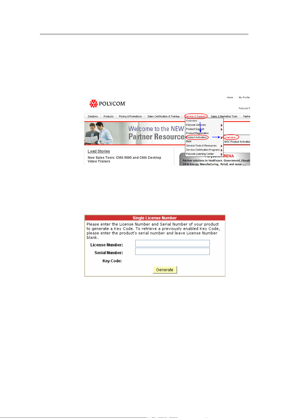
3 Click Service & Support–> Product Activation -> Overview in the
upper navigation bar on the interface.
Figure 2-2 Service & Support Interface
4 Enter the Activate Your Product page. Enter the License Number and
Serial Number of the product in the Single License Number pane, and
then click the Generate button. You can find the license number and
serial number of the product from the document provided with the RMX
1000. Record the activation key displayed in the Key Code field.
Figure 2-3 Activation Key Generating Page
First Time Configuration
Connect PC to RMX 1000
1 Connect your PC to the LAN1 port (the LAN1 port is enabled by default)
of the RMX 1000 with a cross - over network cable, or connect your PC
and RMX 1000 to the same switch in the LAN. Turn on the power switch
at the RMX 1000.
2 Configure the IP address for your PC, which is in the same network
segment as the IP address of the RMX 1000.
3 The default IP address of the RMX 1000 before delivery is:
2-3
Page 19
Chapter 2 – First Time Installation and Configuration
― IP address of the LAN1 port - 192.168.1.254
― Subnet mask - 255.255.255.0
― Default gateway IP address - 192.168.1.1
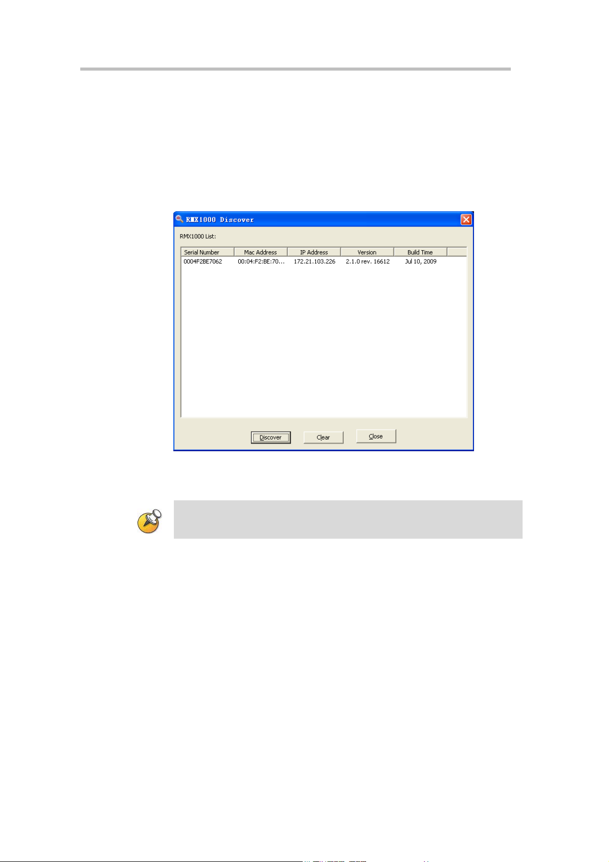
4 You can also view the current address information of the product using
the RMX 1000 Discover tool provided with the device.
a Run the RMXDiscover.exe file in the CD provided with the product.
b Click the Discover button to display the current address information
of the device.
Figure 2-4 RMX 1000 Discover Tool Interface
Logging in to Web User Interface
Please make sure that you are using IE 7.0 or Firefox 3.0(or above) browser in order
to get the best experience when working with RMX 1000 Web UI.
1 Run the Web browser on the PC. Enter http://<RMX 1000 IP address> in
the address bar, and then press Enter.
2 (Optional) Select a language for the Web interface from the drop-down
menu. If the browser or OS of your PC does not support the selected
language, the content is displayed in English.
3 On the Login screen, enter the default User Name (POLYCOM) and
Password (POLYCOM). Click the Login button to enter the Web
configuration interface.
2-4
Page 20

Polycom RMX 1000 User Guide
Figure 2-5 Logging in to the RMX 1000 Web Interface
4 The Product Activation dialog box is displayed. Fill in the activation key
obtained in Obtaining Product Activation Key in the Activation Key box,
and then click the Save button. Click the Close button.
5 The system displays a message asking whether to restart the system or
not. Click Restart Now to validate the activation.
6 After the system restarts, you can enter the Administration -> License
Information interface in the Web configuration interface to check the
activated functions. For the activated functions,
is displayed, or else
is displayed.
Modify the Default IP address
After accessing the RMX 1000 Web configuration interface, you can modify
the default IP address for the device based on the settings of your local
network.
1 Click the IP Network Services configuration item in the RMX
Management pane.
2 In the IP Network Services configuration pane, double-click or right-click
LAN 1 -> Properties.
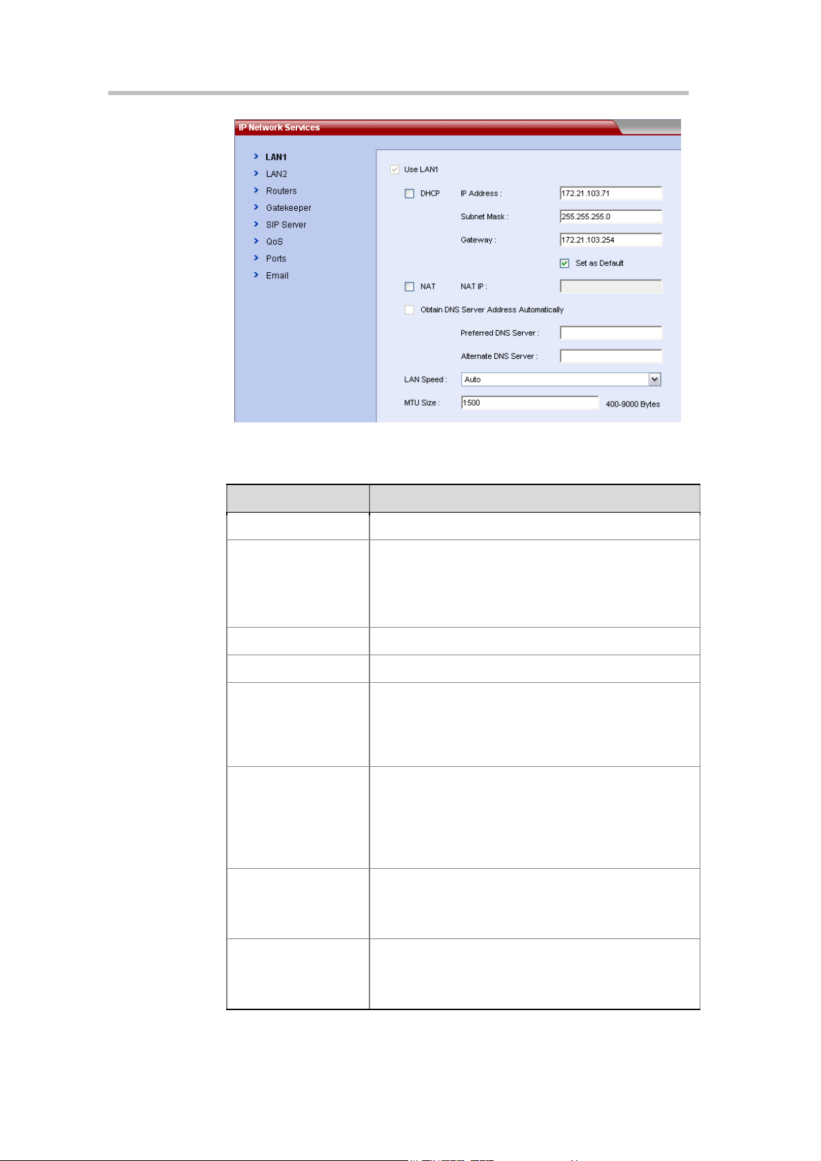
3 In the LAN1 Properties interface, set the IP address obtained from the
network administrator, and configure the device for use on your local
network.
2-5
Page 21
Chapter 2 – First Time Installation and Configuration
Figure 2-7 IP Network Services – LAN Settings
Table 2-1 LAN Port Setting Parameters
Parameter Description
Use LAN1 Enables/disables the network port.
If the user network is configured with a Dynamic Host
Configuration Protocol (DHCP) server, select this option
DHCP
IP Address Set the IP address for this network port.
Subnet Mask Set the Subnet Mask for this network port.
Gateway
NAT
Obtain DNS Server
Address Automatically
to automatically obtain the IP address.
Deselect this option to use a static IP address, in which
case you need to configure the next three options.
Set the gateway address of this port. If
selected and no matched static routes is found, the device
packets will be transmitted via this gateway by default. In
this case, a default route is displayed in the list of Routers
page. For details, see Routers.
The Network Address Translation (
system
address of packet into a public network IP address before
transmission. To enable NAT, select this check box and
then set the public network IP address to be displayed to
the outside in the NAT IP field.
Used in combination with the DHCP option. When the
DHCP check box is selected, this option allows you to
obtain the DNS server address automatically from a DHCP
server in the network.
enables you to translate the private network IP
Set as Default
NAT) function of the
is
2-6
Preferred/Alternate
DNS Server
If you did not select the option for automatic DNS address
discovery, you must enter the preferred/alternate DNS
server addresses here for the device to resolve domain
names.
Page 22
Polycom RMX 1000 User Guide
Parameter Description
Sets the speed/duplex modes for LAN ports. Supported
speed/duplex modes include 10/100M, Full Duplex or Half
Duplex, and the 1000M Network mode. You can also
Auto
LAN Speed
MTU Size
select
Note:
Speed, to ensure that the switch configuration is matched
with the MCU port.
Specifies the Maximum Transmission Unit (MTU) size
used in IP calls and Web communications. If the video
becomes blocky or network errors occur, packets may be
too large; decrease the MTU. If the network is burdened
with unnecessary overhead, packets may be too small;
increase the MTU.
to use Auto-Negotiation with the switch port.
Contact the network administrator before setting LAN
Configuring Other Network Options (Optional)
If necessary, you can configure other network parameters according to the
following procedure:
1 Click the IP Network Services configuration item in the RMX
Management pane.
2 In the IP Network Services configuration pane, double-click or right-click
LAN 1 -> Properties.
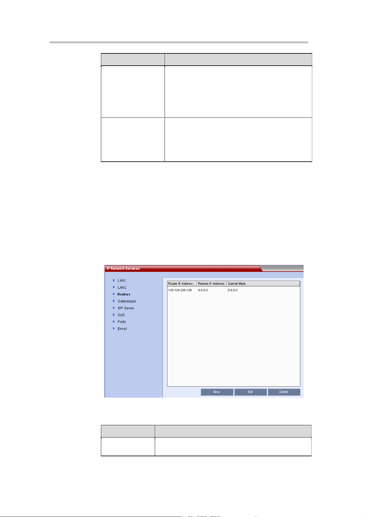
3 Click the Routers tab, and set the routing table information according to
the network topology.
Figure 2-8 IP Network Services – Route Settings
Table 2-2 Routers Setting
Parameter Description
Router IP Address
Set the IP address for the sending router of packet
transmission.
2-7
Page 23

Chapter 2 – First Time Installation and Configuration
Parameter Description
Remote IP
Address
Subnet Mask Set the subnet mask for the target network.
Set the target network address for packet transmission.
4 If your IP network type is SIP only, go to step 7.
5 To register the system to the gatekeeper, click the Gatekeeper tab, and
configure related parameters in accordance with the table below:
Figure 2-9 IP Network Services – Gatekeeper
Table 2-3 Gatekeeper Setting
Parameter Description
Set the IP network type for the RMX 1000 system to
make a call. You need to set it based on the call type
used for the participant's endpoint. It can be set to:
H.323:
Only H.323 calls are supported.
SIP:
Only SIP calls are supported.
H.323 & SIP:
the same time.
H.323 and SIP calls are supported at
IP Network Type
Register to Gatekeeper
Primary (Alternate)
Gatekeeper
Gatekeeper IP Address
Gatekeeper Port
Settings of the gatekeeper related parameters are
available only when the H.323 network type is selected.
Set whether or not to register with the gatekeeper. You
must check this option to set the parameters that follow.
Indicates whether or not the device is registered with the
primary (or alternate) gatekeeper.
Set the IP address for the primary (or alternate)
gatekeeper.
The port number for the primary (or alternate)
gatekeeper.
2-8
System Prefix/E164. Set the E.164 number for the system.
Page 24

Polycom RMX 1000 User Guide
Parameter Description
System H.323 Alias Set the H.323 alias for the system.
6 If your IP network type is H.323 only, go to step 8.
7 To configure the SIP server, click the SIP Server tab, and configure
related parameters in accordance with the table below:
Figure 2-10 IP Network Services –SIP Server
Table 2-4 Configuration Description of SIP Server Parameters
Parameter Description
Set the IP network type for the RMX 1000 system to make
a call. You need to set it based on the call type used for the
participant's endpoint. It can be set to:
H.323:
Only H.323 calls are supported.
SIP:
Only SIP calls are supported.
H.323 & SIP:
same time.
H.323 and SIP calls are supported at the
IP Network Type
Transport Type
Register to Server
Primary
Server/Alternate
Server
Settings of the SIP server related parameters are available
only when the SIP network type is selected.
Set the transport layer protocol used for communicating
with the SIP server. It needs to be consistent with the
protocol supported by the SIP server.
Specifies whether to register RMX 1000 to the specified
SIP server. You need to set the SIP server related
parameters after this function is enabled.
Displays the registration status of the SIP server.
When registration of the preferred server fails, the
alternate server will function as the current in-use SIP
server.
2-9
Page 25
Chapter 2 – First Time Installation and Configuration
Parameter Description
Server Address
Server Port
Server Domain Name
User Name
Password Password corresponds with the user name.
Outbound Proxy
Server
8 Click the OK button to complete the configuration.
For more network service configuration information, see IP Service Settings.
Synchronizing System Time
Before holding a conference using the RMX 1000 system, you need to first
synchronize the system time to ensure that the conference scheduling time is
consistent with your local time.
Provides the IP address of SIP server for registration
service.
Provides the connection port of SIP server for registration
service.
Provides the domain name of SIP server for registration
service.
User name provided by the SIP server for the registered
user.
For communication with the SIP server when the RMX
1000 system is configured on the internal network, an
outbound proxy server is required to implement traversal
of the firewall/NAT. In this case, you need to set the IP
address and port number for the outbound proxy server.
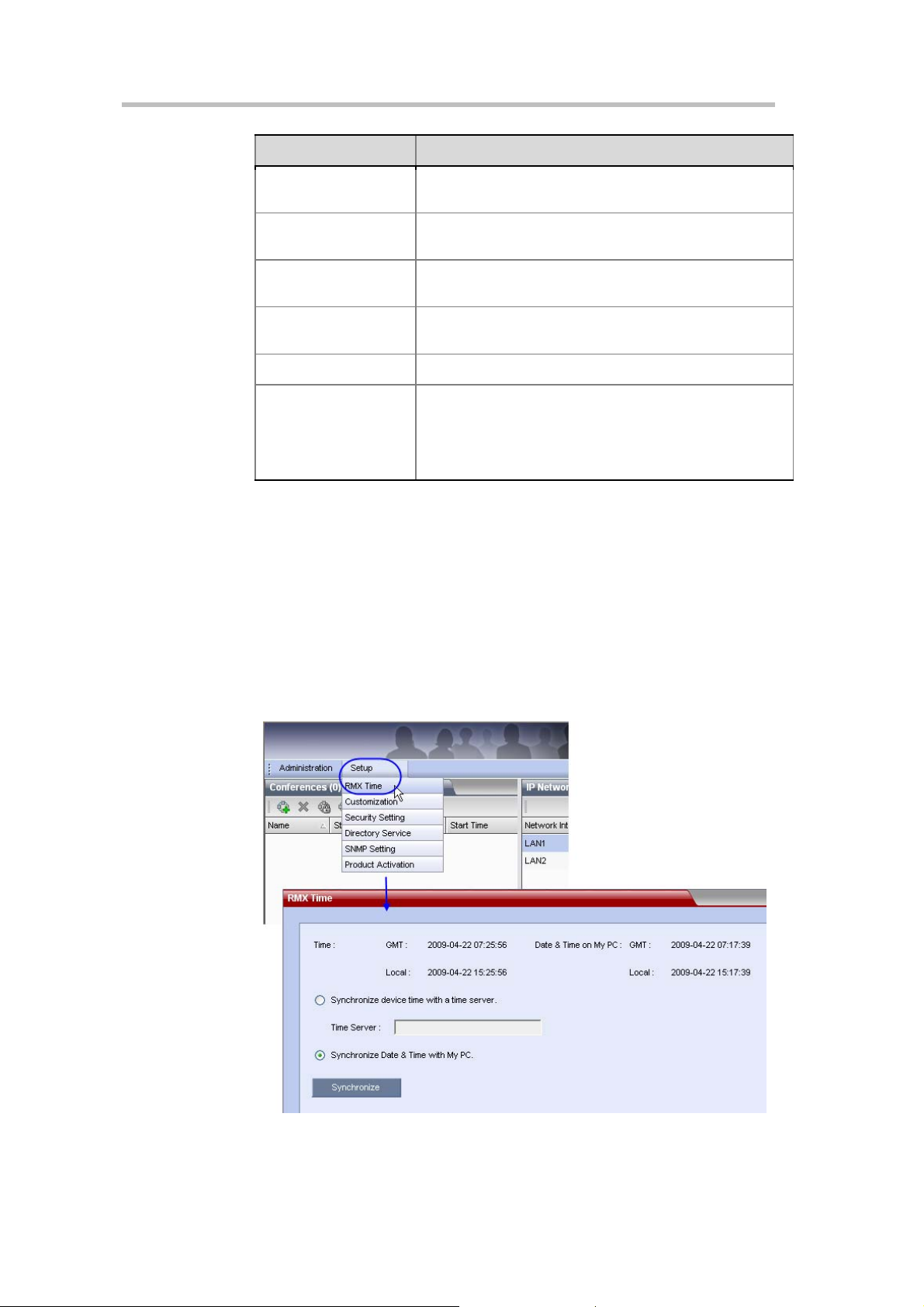
1 In the Web configuration interface, click Setup -> RMX Time to go to the
system time configuration interface.
Figure 2-11 RMX Time
2-10
Page 26

Polycom RMX 1000 User Guide
2 Select a time synchronization mode:
― Select the Synchronize device time with a time server option to
synchronize the device time with a network time server. In this case,
enter the IP address or domain name for the time server in the Time
Server field.
― Select the Synchronize Date&Time with My PC option to
synchronize the device time with your PC that is connected to the
system.
3 Click the Synchronize button to proceed with the synchronization. Then,
click Close.
2-11
Page 27

Page 28
Basic Operation
This chapter introduces the Web UI components of the RMX 1000 and
common operations, and how to start a simple conference. The goal of this
chapter is to provide a quick guide on how to start a conference with
minimal effort.
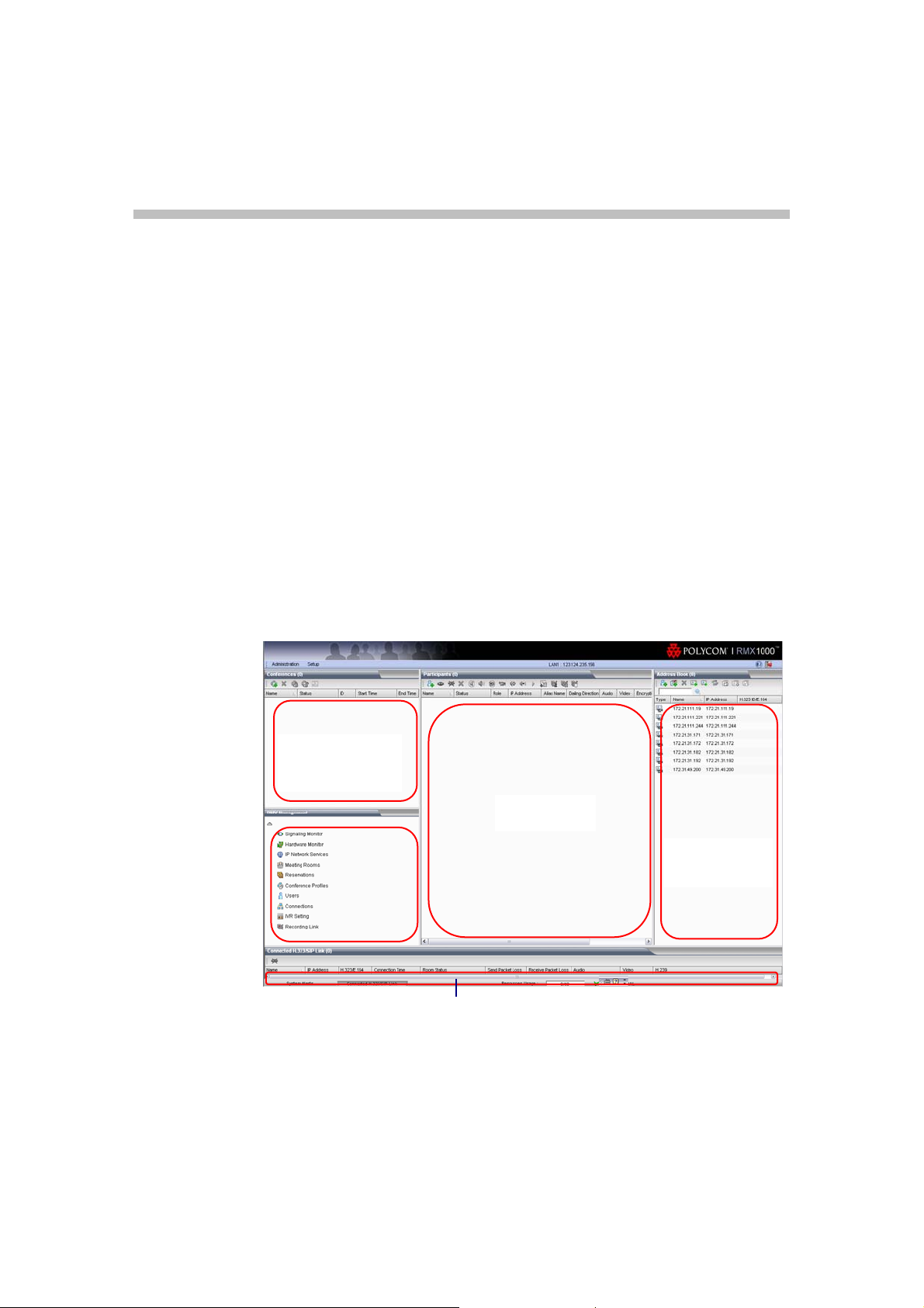
RMX 1000 Screen Components
The Web configuration homepage of the RMX 1000 consists of five panes:
• Conference List
3
• RMX Management
• List Pane
• Address Book
• Status Bar
Conference List
RMX
Management
Figure 3-1 Layout of the Web Interface
Status Bar
List Pane
Address Book
User Rights
You can log into the Web interface as a conference chairperson, an operator,
or an administrator.
3-1
Page 29
Chapter 3 – Basic Operation
RMX 1000 can support a maximum of 20 users simultaneously connected to Web UI.
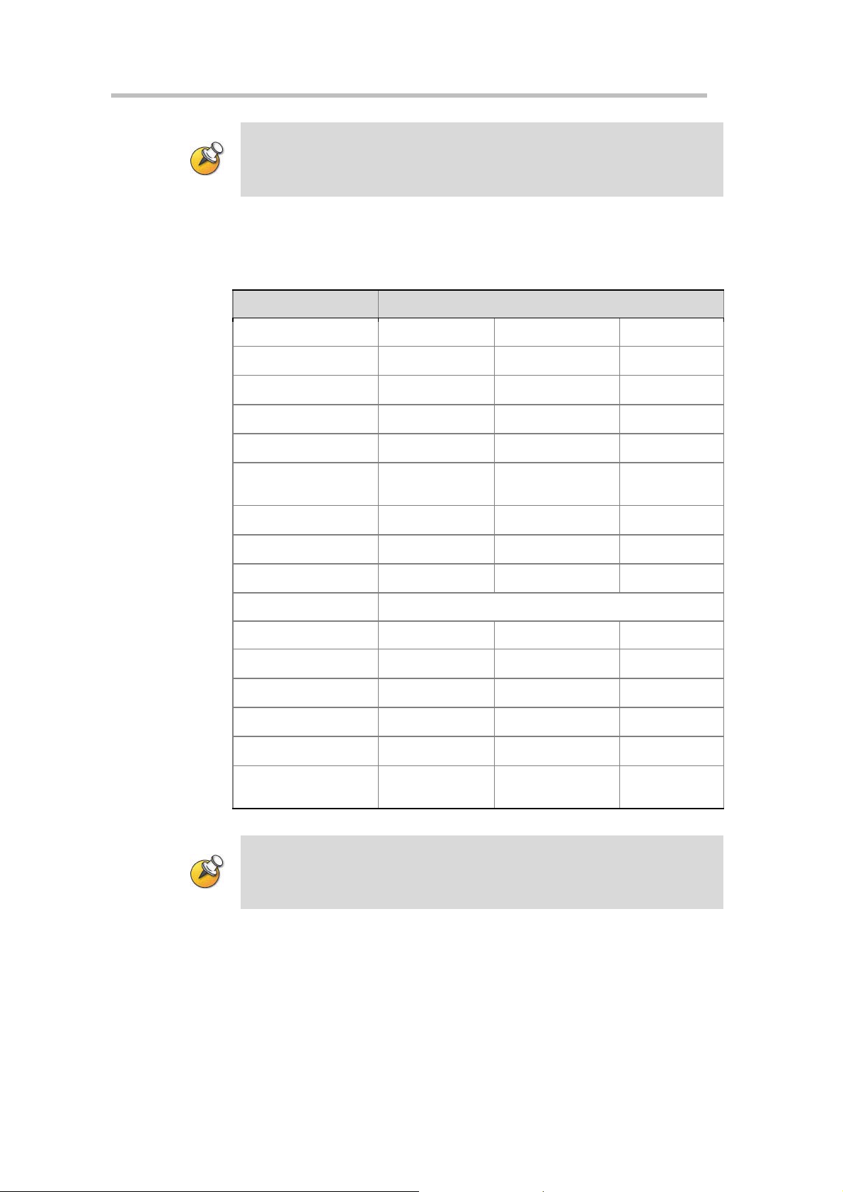
The table below shows the operation abilities of users at different levels
when accessing the Web interface of the RMX 1000.
Table 3-1 List of User Rights
View
Chairperson Operator Administrator
Conference List
List Pane
Address Book
Status Bar
RMX Management
Pane
Conference Alert
Conference Status
Configuration Interface
Chairperson Operator Administrator
Start Conference
Monitor Conference
Monitor Participant
Solve Basic Problems
√ √ √
√ √ √
√ √ √
√ √
System Operations
√ √ √
√ √ √
√ √ √
√ √
√ √
√ √
√ √
√ √
3-2
Modify Device
Configuration
√
The administrator has all operation rights to the Web interface. Unless otherwise
specified, this guide describes the interface operations of an administrator.
Page 30
Pane Layout
Polycom RMX 1000 User Guide
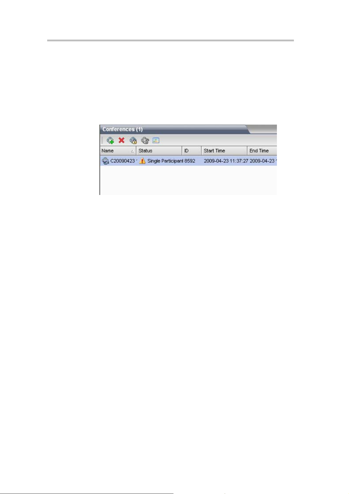
Conference List
The Conferences list pane shows all the conferences running on the current
device and their relevant information, including status, ID, start time and
end time. Here you can create, delete, and lock conferences, as well as view
conference details. The title bar of the pane indicates the number of the
ongoing conferences.
Figure 3-2 Conference List Pane
If you log in as the conference chairperson, the pane only shows the
conferences with no chairperson password. To view the conferences for
which a chairperson password is set, enter the password in the Chairperson
Password box.
RMX Management
The RMX Management pane lists the menu options for conference
configuration, in addition to device maintenance and management. Only
users at administrator or operator levels can configure the menu options.
After an item is selected in the RMX Management pane, the corresponding
configuration items will be displayed in the List pane.
List Pane
The List Pane displays a list of the participants of the ongoing conference by
default. When you click a menu item in the RMX Management pane, the List
Pane displays the related parameter list. You can view all the property
parameters and make specific configurations. The panel title varies with the
selected option.
Status Bar
Located at the bottom of the Web interface, the status bar shows the system
alert information, H.323 link status, resources usage and MCU status.
• System Alerts
The indication bar shows problems with the system. If there are
problems with the system, this indication bar turns red until all the
problems are solved.
3-3
Page 31

Chapter 3 – Basic Operation
• H.323/SIP Link Status
• Resources Usage
Click System Alerts on the left part of the Status Bar to display the
system alert pane. For more information about System Alerts, see System
Alerts.
This indication bar shows in real time the endpoints connected with the
system and relevant information. When an endpoint cannot be
connected to the device, Connected H. 323/SIP Link on the status bar is
highlighted in red. Click this control to open the H.323/SIP link status
pane. For more information about H.323/SIP links, see H.323/SIP Link.
This indication bar shows the number of resources utilized in the system
and the number of resources available in the system.
For example,
resources are available and 2 of them are in use. Click Resources Usage
to view details about resources usage. For the related description, see
Resources Report.
• MCU State
The following explains the information displayed in the MCU State area:
― State: NORMAL- The MCU is functioning normally.
― State: MINOR – The MCU has a MINOR problem but keeps working.
― State: MAJOR- The MCU has a MAJOR problem. MCU behavior
could be affected and attention is required.
Address Book
The Address Book shows the participant information set on RMX 1000 and
the device information stored on the directory server (when the RMX 1000
integrates with a directory server). It enables users to easily add participants
listed in the address book to a conference. Here a user can create and delete
participants or groups, import and export the address book, etc. For more
information about the address book, see Section Address Book.
Common Operations
indicates that 40
3-4
List Sorting
All the list items (such as the conference list, participant list and address
book list) on the Web interface can be sorted by parameter properties.
Click the desired column header in the list. When a small triangle (
appears, you can sort the list in ascending or descending order. After a list is
sorted by a column header in ascending (or descending) order, you can click
the column header again to sort it in opposite order.
)
Page 32

Figure 3-3 List Sorting
Right-click Shortcut Menu
Polycom RMX 1000 User Guide
The Web interface provides right-click shortcut menus for common
operations such as viewing detailed parameters, creating / deleting items,
etc. Alternatively, you can perform these operations by double-clicking the
corresponding list items or by using the corresponding buttons on the
toolbar of the pane.
Pane Sizing
Move the mouse pointer to the border of the pane; when the pointer turns
into an arrow, drag to size the pane while holding down the left mouse
button.
Confirm/Cancel
To confirm your settings on the parameter configuration interface, click the
OK button in the lower part of the interface. To abort your settings, click the
Cancel button.
Shortcut Windows Operations
To enable the user to easily operate RMX 1000, the system utilizes some
Windows shortcut keys.
• After you select a target from the conference list, participant list, address
book list or another list, you can delete it by pressing the Delete key.
• A user can perform standard batch-processing operations by pressing
Ctrl + targets or Shift + targets.
3-5
Page 33

Chapter 3 – Basic Operation
Starting a Conference
There are several ways to start a conference with the RMX 1000:
• Create an instant conference through the conference list pane of Web
interface.
• Directly start a conference using a video endpoint’s remote control.
• Dial into a meeting room. A Meeting Room is a conference that is saved
in the MCU, without occupying any resources. It remains in passive
mode until it is activated by the first participant. For more information
about Meeting Rooms, see Meeting Rooms.
• Reserve a conference (optional): The reserved conference is stored at the
MCU and reserves system resources for the call’s specified time. The
system automatically convenes the conference according to the
reservation time. For more information about conference reservation, see
Reservations.
• Start a conference in the Personal Conference Manager (PCM) interface.
For details, see Creating a Conference.
This part describes how to create a conference instantly through the
Conferences pane and remote control. These two conference types can be
established only when the required system resources are available. They will
be deleted right after their completion to maximize system resources. A user
can view the current available resources in the system through the Resource
Report page of Web interface so as to better schedule conferences. For details,
see Resources Report.
Starting a Conference from the Conferences Pane
To start a conference from the Conferences pane:
1 Click the
Conference - General interface.
Figure 3-4 New Conference Page
button in the Conferences pane to display the New
3-6
The New Conference page displays the default conference name, duration,
profile of conference parameters, and the conference ID automatically
Page 34

Polycom RMX 1000 User Guide
allocated by the system. These options are configurable, but none of these
settings need to be modified to start a conference.
The conference chairperson or organizer should inform other participants of
the conference ID used for the conference, so that they can dial in.
If necessary, set the basic parameters for the conference and add participants
or related supplementary information as needed. For more information of
configuration, see Creating a Meeting Room.
After completing the setup, click OK. After that, the conference list shows
that the new conference is running. If no participant is specified for the
conference, the status is displayed as
, until a participant dials in to
the conference.
Starting a Conference Using the Remote Control – Conference on Demand
A user can enter the call character string that contains the conference ID
through the remote control, and directly start a new conference on RMX 1000.
The dialing string can vary according to the user's endpoint type, whether to
set the conference password and chairperson password, and whether to
invite other participants.
H.323 Endpoint
For an H.323 endpoint, if the endpoint has been registered to the same
gatekeeper as RMX 1000, the dial-in number consists of the E.164 prefix of
RMX 1000 and conference information (such as the conference ID, conference
password, chairperson password and participant address) in the format
below:
<RMX 1000 E.164 prefix>[Conference ID][##Conference
password][##Chairperson password][*Participant's E.164 prefix]
Here, the character in the <> symbol is mandatory, and that in [ ] is optional.
For example:
RMX 1000 E.164 prefix: 925
ID of the conference to be created: 1001
The table below shows the strings dialed by the endpoint under different
scenarios:
Table 3-2 Dial-in String Rule for H.323 Endpoints - Registered to GK
Scenario Dial-in String
Create this conference 9251001
Create this conference and set:
Conference password: 1111
Chairperson password: 2222
Create this conference and invite:
Participant 1 - E.164: 123
Participant 2 - E.164: 321
9251001##1111##2222
9251001*123*321
3-7
Page 35

Chapter 3 – Basic Operation
Scenario Dial-in String
Create this conference, set the
above passwords, and invite the
above participants
If the gatekeeper is not configured on the network, the format of the dial-in
string is as follows:
<RMX 1000 IP address>[##Conference ID][##Conference
password][##Chairperson password][*Participant's IP address]
Here, the character in the <> symbol is mandatory, and that in [ ] is optional.
For example:
RMX 1000 IP address: 172.22.30.40
ID of the conference to be created: 1001
The table below shows the strings dialed by the endpoint under different
scenarios:
Table 3-3 Dial-in String Rule for H.323 Endpoints - Unregistered to GK
9251001##1111##2222*123*321
Scenario Dial-in String
Create this conference 172.22.30.40##1001
Create this conference and set:
Conference password: 1111
Chairperson password: 2222
Create this conference and
invite:
Participant 1 - IP address:
172.22.30.1
Participant 2 - IP address:
172.22.30.2
Create this conference, set the
above passwords, and invite the
above participants
172.22.30.40##1001##1111##2222
172.22.30.40##1001*172.22.30.1*172.22.30.2
172.22.30.40##1001##1111##2222*172.22.30.1*
172.22.30.2
SIP Endpoint
For an SIP endpoint, if the endpoint has been registered to the same SIP
server as RMX 1000, the dial-in number of SIP endpoint consists of the static
route domain name of RMX 1000 and conference information (such as the
conference ID, conference password, chairperson password and participant
address) in the format below:
3-8
[Conference ID][$$Conference password][$$Chairperson password][*
Participant's TEL URI/SIP URI]@<RMX 1000 static route domain name>
Here, the character in the <> symbol is mandatory, and that in [ ] is optional.
For example:
RMX 1000 static route domain name: polycom.com
ID of the conference to be created: 1001
Page 36

Polycom RMX 1000 User Guide
The table below shows the strings dialed by the endpoint under different
scenarios:
Table 3-4 Dial-in String Rule for SIP Endpoints - Registered to Server
Scenario Dial-in String
Create this conference 1001@polycom.com
Create this conference and set:
Conference password: 1111
Chairperson password: 2222
Create this conference and invite:
Participant 1 - TEL URI/E.164:123
Participant 2 - TEL URI/E.164:321
Create this conference, set the
above passwords. and invite the
above participants
1001$$1111$$2222@polycom.com
1001*123*321@polycom.com
1001$$1111$$2222*123*321@polycom.com
If the SIP server is not configured on the network, the format of the dial-in
string is as follows:
<Conference ID>[$$Conference password][$$Chairperson
password][*Participant's IP address or FQDN]@<RMX 1000 IP address>
Here, the character in the <> symbol is mandatory, and that in [ ] is optional.
For example:
RMX 1000 IP address: 172.22.30.40
ID of the conference to be created: 1001
The table below shows the strings dialed by the endpoint under different
scenarios:
Table 3-5 Dial-in String Rule for SIP Endpoints – Unregistered to Server
Scenario Dial-in String
Create this conference 1001@172.22.30.40
Create this conference and set:
Conference password: 1111
Chairperson password: 2222
Create this conference and invite:
Participant 1 - IP address:
172.22.30.1
Participant 2 - IP address:
172.22.30.2
1001$$1111$$2222@172.22.30.40
1001*172.22.30.1*172.22.30.2@
172.22.30.40
Create this conference, set the
above passwords, and invite the
above participants
1001$$1111$$2222*172.22.30.1*172.22.30.2
@172.22.30.40
3-9
Page 37

Chapter 3 – Basic Operation
Dialing method between H.323 and SIP Participants
The RMX system can work as a gateway to enable the H.323 or SIP
participants inviting the SIP or H.323 participants when creating a
conference.
If the GK and SIP server are not configured on the network, dialing is
executed in the same way as for inviting the same IP type endpoint. For
dialing strings please refer to the previous section.
If the RMX 1000 and the endpoint are registered with the GK or SIP server,
the format of the dial-in string is as follows:
Dialing Direction Dial-in String
H.323->SIP
<RMX 1000 E.164 prefix>[Conference ID][##Conference
password][##Chairperson password]<* SIP participant's
TEL URI>
Here, the character in the <> symbol is mandatory, and that in
[ ] is optional.
Note:
participant, if the H.323 endpoint has been registered to the
same gatekeeper as RMX 1000, the SIP endpoint needs to
register the SIP server with a numeric URI and the RMX 1000
should also register the same SIP server.
For an H.323 conference creator to invite a SIP
[Conference ID][$$Conference password][$$Chairperson
password]<* H.323 participant's E.164 prefix>@<RMX 1000
static route domain name>
Here, the character in the <> symbol is mandatory, and that in
SIP->H.323
[ ] is optional.
Note:
For an SIP conference creator to invite an H.323
participant, if the SIP endpoint has been registered to the same
SIP server as RMX 1000, both the H.323 endpoint and the
RMX 1000 need to register the same gatekeeper.
In the gateway scenario, the user can create a conference between an H.323
participant and a SIP participant as a point-to-point call through the
procedures below:
1 Select the Terminate the call when last participant remains option in
the default profile and keep the default idle time value (0). For more
information about conference profile, please see Defining a Conference
Profile.
2 Dial [RMX Prefix]*[another participant’s E.164 or SIP URI]
In that way, when one participant disconnects, the other participant will be
disconnected automatically like in a phone call.
• Conference ID is not mandatory. If the user only dial the RMX 1000 E.164/IP plus
*participant’s E.164/SIP URI/IP, a conference will be created with a random NID.
• The conference ID the user enters for creating a new conference must be unique -
different from existing conference IDs.
• If only one password is entered, it will be defined as a chairperson password. In
this case, there won’t be a conference password and the user will receive the
chairperson privilege.
• The conference password and chairperson password must be different. If a user
enters the same password for both, the call will be rejected.
3-10
Page 38

Polycom RMX 1000 User Guide
Connecting to a Conference–Dialing Methods
To connect an endpoint to an ongoing conference or meeting room, you can
use one of the dialing methods below:
• Dial the IP address of the RMX 1000 system through the remote control
to connect the RMX 1000. If the system is registered to a gatekeeper or
SIP server, dial the E.164 prefix or SIP URL to connect to the system, and
then use the remote control to select a conference in the PCM interface to
join. For details, see Entering an Existing Conference.
• Directly dial in to the conference using the remote control. For details,
see the following sections. In this way, the user must obtain the
conference ID and password (if the conference password or chairperson
password is set) first.
H.323 Endpoint
For an H.323 endpoint, if the endpoint has been registered to the same
gatekeeper as RMX 1000, the dial-in number consists of the E.164 prefix of
RMX 1000 and conference ID. If the conference to be dialed in is set with a
password, you need to add "##Conference password or chairperson
password".
For example:
RMX 1000 E.164 alias: 925
ID of the conference to be dialed in: 1001
Then, the endpoint dials 9251001
If the conference to be dialed in is set with the conference password 1111 and
chairperson password 2222
Then, the regular participant dials 9251001##1111
The conference chairperson dials 9251001##2222
If the gatekeeper is not configured on the network, the dial-in string consists
of the IP address of RMX 1000 and conference ID, separated with ##. If the
conference to be dialed in is set with a password, you need to add
##Conference password or chairperson password.
For example:
RMX 1000 IP address: 172.22.30.40
ID of the conference to be dialed in: 1001
Then, the endpoint dials 172.22.30.40##1001
If the conference to be dialed in is set with the conference password 1111 and
chairperson password 2222
SIP Endpoint
Then, the regular participant dials 172.22.30.40##1001##1111
The conference chairperson dials 172.22.30.40##1001##2222
For the SIP endpoint, you can use the remote control to directly dial in to the
conference only when RMX 1000 and endpoint are registered to the same SIP
3-11
Page 39

Chapter 3 – Basic Operation
server. If the endpoint is registered to another SIP server, you can only first
call the SIP URL of RMX 1000 to set up a connection, and then access the
conference by entering the conference ID as IVR service prompted or through
the PCM interface. The dial-in number of SIP endpoint consists of the static
route domain name of RMX 1000 and conference ID in the format below:
Conference ID [$$Conference password or chairperson password]@RMX
1000 static route domain name
Here, the character in [ ] is optional. It needs to be entered when the
conference is set with a conference password or chairperson password.
For example:
RMX 1000 static route domain name: polycom.com
ID of the conference to be dialed in: 1001
Then, the endpoint dials 1001@ polycom.com
If the conference to be dialed in is set with the conference password 1111 and
chairperson password 2222
Then, the regular user dials 1001$$1111@ polycom.com
The conference chairperson dials 1001$$2222@ polycom.com. If RMX 1000 is
not registered to an SIP server, the dial-in number consists of the IP address
of RMX 1000 or FQDN and conference ID in the format below:
Conference ID [$$Conference password or chairperson password]@RMX
1000 IP address or FQDN
Here, the character in [ ] is optional. It needs to be entered when the
conference is set with a conference password or chairperson password.
For example:
RMX 1000 IP address: 172.22.30.40
ID of the conference to be dialed in: 1001
Then, the endpoint dials 1001@172.22.30.40
If the conference to be dialed in is set with the conference password 1111 and
chairperson password 2222
Then, the regular user dials 1001$$1111@172.22.30.40
The conference chairperson dials 1001$$2222@172.22.30.40
If the conference ID the user entered does not exist, RMX 1000 will create a new
conference with this conference ID. For more information, see Starting a C onference
Using the Remote Control.
3-12
Page 40

Conference Profiles
A conference profile is used to pre-define the basic parameters for conference
scheduling, such as the bandwidth, encryption, and video quality. All
conferences will be created on the basis of conference profiles. By saving
conference profiles on the RMX 1000, users can conveniently and rapidly
schedule new conferences without performing repeated configurations. The
following parameters generally decide the video conference quality.
• Bit Rate – The transmission rate of the audio and video streams. The
higher this value is, the better the displayed video quality.
• Video Protocol, Video Format, and Frame Rate – These parameters
define the quality of the video picture. When an endpoint is connected to
the conference, it will select a video capability based on the video
parameters set for the conference. For example, if the video protocol for
the conference is H.264, an endpoint that supports the H.264 protocol
will select H.264 for video coding when it connects to this conference.
4
The following features are commonly used to define a conference:
• H.239 Dual-stream – An H. 239 compliant endpoint can simultaneously
send and receive two channels of conference video streams: dynamic
conference video and PC screen contents.
• Encryption – The system provides AES 128-based multimedia
encryption to strengthen conference security.
To set a conference profile, click Conference Profiles in the RMX
Management pane. The list pane shows the profiles saved on the current
device and their summaries.
4-1
Page 41

Chapter 4 – Conference Profiles
Figure 4-1 Conference Profile List
RMX 1000 is provided with default built-in conference profiles so that users
can create conferences easily.
Table 4-1 Default Conference Profiles
Profile Name Parameter
Default_768_CIF_H264Content
(Default Profile)
768_4CIF_H264Content 4CIF H.264, H.264 dual-stream
384_CIF_H264Content 384 CIF, H.264 dual-stream
384_CIF_H263Content 384 CIF, H.263 dual-stream
2M_720p_H264Content
(Appears only if the H.264 720p
option is activated.)
H.264 dual-stream
2M 720p, H.264 dual-stream
Defining a Conference Profile
To create a conference profile, click the button in the Conference Profile
list pane or right-click in the blank area in the pane, and then click New
Profile. The New Profile interface appears. The RMX 1000 fills in default
settings. For basic operations, you only need to define the display name of
the profile. To configure parameters, see the description below.
4-2
Page 42

Figure 4-2 New Profile Settings
General Settings
Polycom RMX 1000 User Guide
On the New Profile page, click the General tab to display the interface for
configuring general parameters. The table below explains the detailed
meanings of these parameters.
Table 4-4 General Parameters
Parameter Description
Enter a unique name to identify this profile.
Display Name
Line Rate
Encryption
Auto Mute
Note:
This is the only mandatory parameter when you
create a new profile.
Select the conference line rate. Line rate indicates the rate
that integrates video, audio, and data contents.
Set whether to enable the AES encryption function for this
profile.
Note:
The RMX 1000 version for some geographic areas may
not allow for the encryption option.
Encryption is an optional function of RMX 1000. This
function is only available after you purchase its license
and activate this function. To obtain this function, please
contact your supplier.
If this check box is selected, after an endpoint dials into the
conference, the RMX 1000 will automatically mute it.
4-3
Page 43

Chapter 4 – Conference Profiles
Parameter Description
Auto T e rminate
Minimum ports to be
reserved
If this check box is selected, the system will automatically
terminate the conference when any of the following
conditions is satisfied:
Before First Join - No participant joined within the
predefined period since the conference started. The
default idle time is 10 minutes.
After Last Quit - All participants have left the conference,
and the idle period has reached the predefined time.
The default idle time is 1 minute.
When Last Participant Remains - Only one participant
remained in the conference, and that period has
reached the predefined time. The default idle time is 1
minute.
Auto
is selected by default, indicating that the system will
decide the number of allowed video participants according
to the number of actual idle resources when the
conference is created. When
specify the minimum number of video participants so that
the system can reserve the appropriate resources for this
conference when it is being held.
Auto
is not selected, you can
Maximum ports to be
used
Limit Personal
Conference
Management (PCM)
access to conference
creator only
First Participant in a
Call Slide
Talk Hold Time
Auto
is selected by default, indicating that the system will
decide the number of allowed video participants according
to the number of actual idle resources when the
conference is created. When
set the maximum number of video participants. You can
add the maximum number of video participants set here
when you hold a conference using this template.
When this check box is selected, only the participant who
created this conference can view the PCM menu and
control the conference.
With this option selected, the image of the first joined
participant will not be shown at his endpoint. Instead, the
endpoint of the first participant will display the default idle
images dispatched from the system when this participant
enters the conference.
When the period a participant speaks reaches the
predefined time, this participant will become the primary
speaker. Under different video modes, the speaker's
image may be displayed in full screens on other
participants' screens or switched to the largest window in
the screen layout.
Auto
is not selected, you can
Video Quality
To set the video quality parameters for the conference, click the Video
Quality tab. A user can adjust the quality parameters of the site image
during the conference, or define the quality parameters of the second channel
video when sharing the dual-stream contents.
4-4
Page 44

Polycom RMX 1000 User Guide
Figure 4-3 Video Quality Setup Page
Depending on the user's selection in People Video Definition, the profile can be
defined as two types of conference modes: the Continuous Presence (CP)
conference and the video switching conference.
• CP conference: The endpoint screen can simultaneously display the
images of multiple sites. A user can also choose a preferred screen
layout. However, this mode occupies more MCU video resources.
• Video switching conference: The system only forwards the video
stream without encoding or decoding. Therefore, this mode does not
utilize the MCU video resources, and more conferences can be held. In
the video switching conference, all the participants' endpoints use the
same bandwidth and video capability, and can only display one site at a
time. A user can use the voice activation feature to switch to see each
conference site. The maximum number of video switching conferences
supported by the system is equal to the number of participant
connection resources available and is not related to the video capability
of an endpoint. The video switching conference has the following
limitations:
― Only one type of conference screen layout is supported
― Only the lecture mode is supported.
― Settings for the conference skin and Message Overlay are not
available.
― Site name setting during a conference is not allowed.
― The PCM menu is not available.
4-5
Page 45

Chapter 4 – Conference Profiles
Defining People Video Quality
To define the video quality of CP conference:
As described in the table below, select the highest resolution of CP
conference in the People Video Definition field.
Table 4-5 People Video Definition
Parameter Description
Up to H.264,
CIF/SIF
Up to H.263,
4CIF/4SIF, 15FPS
Up to H.264,
4CIF/4SIF
It is used for the screen display of ordinary quality. The
conference video can be best encoded/decoded with the H.264
protocol and displayed with the CIF/SIF resolution, requesting
the lowest bandwidth requirement and occupying the minimum
system resources. In the conference, each endpoint only
occupies one video connection resource.
It is used for the screen display of high quality. The conference
video is encoded / decoded with the H.263 protocol and
displayed with the 4CIF/4SIF resolution and 15FPS frequency,
requesting a higher bandwidth. In the conference, each
endpoint only occupies one video connection resource.
It is used for the screen display of higher quality. The
conference video is encoded/decoded with the H.264 protocol
and displayed with the 4CIF/4SIF resolution. The endpoint
must support the H.264 protocol and the bandwidth cannot be
lower than 256Kbps. Each endpoint in the conference utilizes 2
video connection resources.
The conference video can be best encoded/decoded with the
H.264 protocol and displayed with 1280x720 (720p) HD
resolution, utilizing more system resources. The conference
under this mode has the following restrictions:
The endpoint must support the H.264 protocol and 720p
resolution, and the bandwidth cannot be lower than 832Kbps.
Otherwise, the conference video will be degraded to the
4CIF/CIF resolution display or H.263 coding depending on
the capability of the endpoint that joins in the conference.
It supports only the Same Layout video mode, and the same
(Optional with
keycode) Up to
H.264, 720P
(Common Layout)
video layout is displayed for all the conference sites.
When there is no other CP conference concurred, the system
supports convening a maximum of 5 720p conferences at
the same time on condition that each conference only has
two participants and they all support 720p.
When a 720p conference is ongoing, the screen of the
participant’s endpoint displays only the conference video. For
the PCM related information, see Personal Conference
Manager (PCM).
Note:
Up to H.264, 720P is an optional function of the RMX
1000 and will not be available until a license is purchased. If the
license for this function is not activated, the device does not
display the related options. To obtain this function, please
contact your supplier.
To define the video quality of video switching conference:
4-6
Select Video Switching Highest Common from the People Video Definition
field.
Each endpoint under this mode occupies only one video connection resource,
Page 46

Polycom RMX 1000 User Guide
and the conference video can be displayed with the best HD resolution of
1280x720 (720p). However, all the endpoints must support the H.264 protocol
and 720p resolution, and the bandwidth cannot be lower than 832Kbps, or
else the display of conference video will be, depending on the capability of
the participant's endpoint, degraded to the resolution of 4CIF or CIF, or
H.263 code.
The RMX supports a maximum of 20 video resources and 20 audio resources. The
number of connection resources supported by the device in the actual conference
depends on the number of resources purchased by the user.
Defining Content Video Quality
When the endpoint sends dual streams, the RMX 1000 system applies
different encoding and decoding policies to the people video stream and
content video stream. See the table below, which provides the video
parameters for setting the second channel of content image.
Table 4-8 Video Quality Parameters – Second-channel Video Dual-stream Definition
Parameter Description
Set the video protocol used for the dual-stream video. You can
select the H.264 or H.263 coding/decoding algorithm based on
the endpoint capability and network bandwidth. When None is
Content Setting
selected, it indicates dual streams are not enabled.
Note:
If this setting is H.264, when an endpoint that only
supports H.263 protocol joins in the conference, an H.264
endpoint that originally sent dual streams will terminate sending
dual streams and resend them using the H.263 protocol.
H.239 Setting
Send Content to
Legacy
Endpoints
Video Settings
To set the screen layout of conference on the endpoint screen, click the Video
Settings tab on the New Profile interface.
The H.239 protocol is used to send dual streams. You can
select three kinds of video quality as needed:
Graphics: For the standard video display
High-resolution graphics: For the graphic detail display of high
quality broader bandwidth is required.
Live Video: For full-motion of dynamic video display. The
broadest bandwidth is required.
When this option is enabled, legacy endpoints that do not
support the H.239 protocol will still be able to view Content in
the conference. However, the Content video will be sent to
these endpoints instead of the People video when Content is
introduced to the conference. Legacy endpoints will not be able
to share content – they will only be able to view. Modern
endpoints which support H.239 will continue to view dual
streams (People and Content simultaneously) and be able to
share content.
4-7
Page 47

Chapter 4 – Conference Profiles
Figure 4-4 Video Settings
In the Video Mode drop-down menu, you can set the following video modes
for conference:
• Lecture Mode: All the conference participants view the selected lecturer
in full screen, and the lecturer's endpoint will display the screens of
other sites in accordance with the layout set here. A user can specify a
lecturer after the conference is initiated. For details, see the lecture mode
description in Section Changing Conference layout.
• Same Layout: All the participants' endpoints in the conference will
display the same screen image according to the layout set here. This
setting will allow sites to see their own loopback images, which are
normally not included as part of the layout.
• Conference Layout: Each participant's endpoint in the conference can
display a different screen layout. In this mode, the operator can enter the
participant parameter page through the Web interface, and perform
personalized settings for the screen layout displayed on the video
endpoint of each site. For details, see Setting Conference Layout for
Participant’s Endpoint . While, the participant can define a personal
layout by operating the PCM interface via the remote control. For
details, see Click & View.
Based on the selected video mode, a user can set to automatically select the
screen layout according to the number of added participants or specify a
fixed screen layout:
4-8
To set automatic layout:
1 Click Auto at the left part of the layout setting area to display the
automatic screen layout pane.
2 Select a maximum screen layout so that the conference site displays at
most the number of multi-screen windows set here. In this mode:
Page 48

Polycom RMX 1000 User Guide
― When the number of participants is smaller than or equal to the set
number of multi-screens, the system displays the multi-screen image
according to the actual number of participants and in line with the
default rule. The table below shows the default rule.
― When the number of participants is greater than the set number of
multi-screens, the system uses the voice activation feature, and
switches to display the first participants who speak loudest with the
largest multi-screen layout selected here. If the number of
participants is greater than 4 and the maximum selection is
system will display the first four participants who speak loudest
using the
Table 4-9 Default Rule of Automatic Layout
Number of Participants Multi-screen Layout
layout.
, the
1
2
3-4
5-6
7-8
9
10
11- 13
14-16
16+
To specify a fixed layout:
1 Click at the left part of layout setting area the number of multi-screen
windows to be displayed to expand the corresponding layout pane.
2 Select a screen layout so that the conference site displays the participant's
image always according to the layout selected here.
Conference Skin Settings
Click the Skins tab in the New Profile interface to enter the interface for skin
settings. Here, you can define the background picture and outline color of the
CP image, and browse the skin effect in the browsing area at the lower part
of the interface.
4-9
Page 49

Chapter 4 – Conference Profiles
Figure 4-5 Meeting Room Parameter Setup Interface
Customize settings for the conference skin by referring to the table below:
Table 4-11 Parameter Description of Conference Skin
Parameter Description
Background Picture Select the background picture for the conference screen.
Outline Color
Full Screen
If the conference is set to a video switching conference, a user cannot set conference
skin on this interface.
Conference Recording
RMX 1000 can work with Polycom RSS 2000 recording server to record
conferences. Click the Recording tab on the New Profile interface to enter the
related information and set the recording parameters.
A user can respectively set the outline colors of screens for
the conference lecturer and regular participant.
When this option is selected, multi-screens will extend the
full screen, without spacing.
4-10
Page 50

Polycom RMX 1000 User Guide
Figure 4-6 Recording Parameter Setup Interface
The table below explains the configuration parameters.
Table 4-12 Conference Recording Configuration
Parameter Description
Enable Recording
If an RSS 2000 is available on your network, you can select
this option to enable the recording function.
Select the start time of the conference recording:
Immediately – The recording automatically starts
immediately after the first participant joins the conference.
Upon Request – The operator or chairperson starts the
Start
recording manually. After this option is selected, the
recording can be manually started through the Web interface
or DTMF function. For more information, see Recording
Control.
If this option is selected, the endpoint screen displays the
recording indicator icon to inform participants that the
Enable Recording
Indication
Terminate
conference if
recording fail …
conference is being recorded:
Note:
Recording indication is not supported in video switching
conference and HD 720p conference.
If this option is selected, the system will terminate the
conference when the recording fails or there is no endpoint in
the lobby.
Audio Only If this option is selected, only the audio will be recorded.
• The recording parameters can be set here only after the IP address of the RSS
2000 is configured on the Recording Link interface. For how to set Recording Link,
see Recording Setup.
• The Recording Link occupies one conference resource.
• If the encryption function is enabled in the C onferen ce Profiles->General
interface, recording will succeed only when the RSS 2000 also supports
encryption.
4-11
Page 51

Chapter 4 – Conference Profiles
Message Overlay
When a message needs to be sent to all the participants in a conference, you
can set the message overlay of conference to be displayed on all participants’
endpoint screens.
Click the Message Overlay tab on the New Profile interface to set the message
overlay parameters.
Figure 4-7 Message Overlay Setting Interface
Set the message overlay with reference to the table below:
Table 4-13 Description of Message Overlay Setting Parameters
Parameter Description
Enable
Message T e xt Enter the content to be displayed.
Font Size Set the font size of the message overlay.
Color
Display
Repetitions
Display Speed
Vertical Border
Contrast Move the slider to set the contrast of the message overlay.
Select this option to enable message overlay. Then you can
set other parameters.
Set the color-matching scheme for the message overlay font
and background.
Move the slider to set the display times of the message
overlay.
Move the slider to set the display speed of the message
overlay.
Move the slider to set the vertical boarder of the message
overlay.
4-12
Page 52

Site Name
Polycom RMX 1000 User Guide
A user can set the site name (endpoint name), so as to label each site when
viewed onscreen. The site name displayed for each connected participant
comes from the system name configured within the endpoint.
Click the Site Name tab on the New Profile interface to set the site name
parameters.
Figure 4-8 Site Name Setting Interface
Here, you can specify the displayed font size and position for the site name.
If Always show site name is selected, the name of each site will be always
displayed during the conference.
Advanced Options
A user can set advanced options in the conference profile to fine-tune video
and audio quality.
To set advanced options, click Advanced Options in the New Profile interface.
Figure 4-9 Advanced Options Setting Interface
The table below describes the related parameters.
4-13
Page 53

Chapter 4 – Conference Profiles
Table 4-14 Parameter Description of Advanced Options
Parameter Description
Video Clarity
Lost Packet
Recovery
This option is enabled by default. It is used to improve the
clarity of video received from an endpoint which has low
bandwidth and/or low resolution.
Lost Packet Recovery (LPR) is an algorithm designed to
protect IP video calls against the impact of network packet
loss. This option is enabled by default. In case of packet loss
during network transmission, the packet recovery mechanism
will be automatically activated if the endpoint experiencing
packet loss also supports the LPR protocol. This function can
effectively improve the decreased video quality caused by
packet loss.
Echo Suppression
Keyboard Noise
Suppression
This option is enabled by default. It is used to prevent the
sound of near site echoing being played to the far site(s).
This option is disabled by default. It specifies whether the
system mutes audio sent to the far site when keyboard tapping
sounds are detected at the near site(s).
Modifying a Profile
To modify a saved profile, right-click in the Profile list, and then click Profile
Properties to modify its properties.
Deleting a Profile
To delete an existing profile, select it in the Profile list, and then click .
Alternatively, right-click the profile to be deleted and then click Delete
Profile.
A profile in use cannot be modified or deleted.
Setting a Default Profile
After a default profile is set, the endpoint will use it when creating a
conference directly through the remote control. In addition, when a user
creates a meeting room, reserves a conference or holds an instant conference
via the Web interface, the default profile will be used unless otherwise
specified.
To set a default profile, right-click the profile to be defined in the Profile list,
and then click Set as Default. After that, the icon of the profile becomes
A profile with the AES encryption function enabled cannot be set as the default profile.
4-14
.
Page 54

Recording Link
The RMX 1000 supports the recording link function. It can work with the RSS
2000 to record conference content. After the recording setup is completed,
when the conference starts, the RMX 1000 will first call the participants in the
participant list, and then call the configured RSS 2000 to record the
conference. The recording link is displayed in the List pane as a regular
participant, thereby enabling users to view and control the recording status
easily.
To record a conference running on RMX 1000 through RSS 2000, configure
the related parameters according to the procedure below:
1 Configure the information of RSS 2000 to be connected in the Recording
Link interface. For details, see the text below.
5
2 The profile used for the conference has enabled the recording function.
For details, refer to Conference Recording.
Recording Setup
In the RMX Management pane, click Recording Link. The Recording Link
interface appears in the list pane located on the right side. Here you can view
the IP address and alias configured for the RSS 2000.
Figure 5-1 Recording Link
5-1
Page 55

Chapter 5 – Recording Link
Right-click the default empty link or configured RSS IP address in the
interface, and then click Properties to display the Recording Link -> General
interface.
General Settings
Figure 5-2 Recording Link - General
The table below explains the detailed meanings of these parameters.
Table 5-1 Parameter Description for Recording Link - General
Parameter Description
RSS 2000 IP
Address
RSS 2000 Alias
Alias Type Set the alias type of the RSS 2000: H.323 or E.164.
DTMF Code Setting
To set the recording control operations and rights for use by connected
endpoints, click the DTMF Codes tab.
Enter the IP address of the RSS 2000 to be connected. This item
is optional if an alias is set in the Alias check box below.
Enter the E.164 number or H.323 alias of the RSS 2000 in
accordance with the selected alias type. This item is optional if
the IP address of the RSS 2000 is set.
Note:
If the alias is used for recoding call, both RMX 1000 and
RSS 2000 need to be registered to the same gatekeeper.
5-2
Figure 5-3 Recording Link - DTMF Codes
Page 56

The table below explains the detailed meanings of these parameters.
Table 5-2 Parameter Description for Recording Link - DTMF Codes
Parameter Description
Name Name of the recording operation
DTMF Code
Permissions
Recording Control
Polycom RMX 1000 User Guide
Set the remote control key combination used to perform the
operation. The default numbers can be customized. For
example, the default DTMF code for the Start Recording
command is *2, you can press the keys *2 to start conference
recording.
Note:
Before using the DTMF command, enable the DTMF
function of the endpoint according to that endpoint's instructions.
Set the rights of using DTMF codes. Chairperson indicates that
the DTMF is available to the conference chairperson only;
Everyone indicates that the DTMF is available to all
participants.
When a conference is going on, you can view and control the status of the
configured recording link. In the Conferences list pane, select the desired
conference. Then the list pane located on the right side shows the defined
participants and connected participants, among which the recording link is
indicated by the
icon.
Figure 5-4 Recording Control
When a conference is going on, you can perform the following recording
control operations through the recording buttons in the list pane or the
right-click shortcut menu.
•
- Start recording
•
•
• The conference chairperson can also control recording in the PCM interface. For
- Pause recording
- Stop recording
details, see Recording a Conference.
• For more information about the recording control operations of the RSS 2000, see
RSS 2000 User Guide.
5-3
Page 57

Chapter 5 – Recording Link
Recording Properties
To view the status between the recording link and RMX1000, double-click the
recording link, or right-click it and select Properties to view parameters.
• General – Displays the name, address, alias and other information.
• DTMF Code – A participant can use DTMF codes to send commands to
the RSS server in real time, so as to easily complete recording operations.
• Connection Status – Displays in real time the RSS-RMX1000 connection
status and disconnection cause.
5-4
Page 58

Meeting Rooms
A Meeting Room is a conference saved on the MCU in passive mode, without
using any system resources. A Meeting Room is automatically activated
when the first participant dials into it. Once activated, a Meeting Room
functions as any ongoing conference. All Meeting Rooms are based on a
Conference Profile. The RMX 1000 can support up to 5000 meeting rooms.
To set a meeting room, click Meeting Room in the RMX Management pane.
The list pane shows the meeting rooms saved on the RMX 1000 and their
summaries, such as the meeting room name, conference ID, conference
duration, conference password, chairperson password, and conference
profile. Here you can create, modify and delete meeting rooms.
6
Figure 6-1 Meeting Rooms List
Creating a Meeting Room
To create a meeting room, click the button in the list pane or right-click
in the blank area of the pane and then click New Meeting Room. The New
Meeting Room -> General interface is displayed.
6-1
Page 59

Chapter 6 – Meeting Rooms
General Settings
Figure 6-2 New Meeting Room - General
The table below explains the detailed meanings of these parameters.
Table 6-1 Parameter Description for New Meeting Room – General
Parameter Description
Meeting Room
Name
Profile
Duration
Conference ID
Set a unique name to identify the meeting room. When a
meeting room is created, the system will automatically
generate a unique name for it.
Select the profile to be used for this conference from the
drop-down list. The lower part of this option displays the major
parameter values defined for the profile:
Line Rate:
participant in the conference.
Minimum ports to be reserved/Maximum ports to be
used:
conference participants. Automatic indicates that the number
of video participants is determined according to the available
resource of the RMX 1000.
The conference profile defines the basic parameters of
conference scheduling, such as the bandwidth, encryption,
and video quality. For more information on conference profiles,
see Conference Profiles. When a conference is created, the
system selects the default profile of the device by default.
Specify the conference duration in the range of 0-24 hours. The
input format is H:M and the default value is 2:0, namely, 2 hours.
When a meeting room is created, the system automatically
allocates a conference ID. You can also set a unique conference
ID on the device. To directly dial into the conference, the
participant must know its ID.
The maximum bandwidth to be used by each
The minimum/maximum number of allowed
6-2
Conference
Password
Enter the conference password. To connect to this conference,
the participant must enter this password. If this parameter is
empty, it means the conference has no password.
Page 60

Polycom RMX 1000 User Guide
Parameter Description
Enter the password that identifies the chairperson ID. The
Chairperson
Password
Dial Out Manually
system will authorize more rights to the chairperson. If this
parameter is empty, it means the conference has no
chairperson.
When enabled, the system will not automatically call the
participants defined in the meeting room to join the conference
unless the administrator dials out manually.
Participant setup
You can add the participant information to the invited participant list for the
meeting room. When the meeting room is activated, the system will
automatically call the participants defined in the meeting room to join the
conference. To set the invited participant list, click the Participants tab to
enter the relevant interface, as shown below.
Figure 6-3 New Meeting Room - Participants
You can add participants to the list in the following two modes:
To create a participant in the list:
1 Click the New button to create a participant.
2 The popup configuration interface is the same as that for adding a new
participant to the address book. For explanation on the configuration
parameters, see Creating a Participant in the Address Book.
To add a participant from the address book to the list:
1 Click the Add from Address Book button.
2 In the popup address book, select the participant to be added, and then
click the OK button. To select multiple participants at one time, click
these participants one by one while pressing down the Ctrl key, or select
adjacent ones while pressing down the Shift key.
6-3
Page 61

Chapter 6 – Meeting Rooms
To edit or delete a participant that is added to the list, select it, and then click
the Edit or Remove button. A user can also click multiple participants to be
deleted one by one while pressing down the Ctrl key, or select adjacent ones
while pressing down the Shift key.
The table below shows the meanings of other optional parameters.
Table 6-2 Parameter Description for New Meeting Room – Participants
Parameter Description
Lecture
Only participants in
the above
participant list can
dial in
This option is available only when the video mode for the
conference profile of meeting room is set to Lecture Mode.
About settings of the video mode, see Video Settings. After
adding participants to the list, you can select a participant from
the drop-down list to act as the lecturer. By default,
selected, meaning that the system uses voice activation to
switch between the layouts, and the participant who speaks
loudest will be selected as the lecturer. When the conference is
running under the Lecture Mode, all participants’ endpoints
display the lecturer in full screen, and the lecturer’s endpoint
can time-switch to display other conference sites in rotation.
When this option is selected, only the participants defined in
the Participant List can dial into the conference.
Auto
is
If this option is selected, after you click OK, the system will
automatically send an email message to notify each participant
Email Notification
in the Participant List to join the conference. This option is
enabled only when SMTP is configured in the IP Network
Services->Email interfaces. For more information, see Email.
Other Information
To configure other information for the meeting room, click the Information
tab. Here you can configure conference notes, site details, accounting
information, etc.
Modifying a Meeting Room
To modify a meeting room, double-click the desired meeting room in the
meeting room list; or right-click the meeting room, and then click Meeting
Room Properties. For explanation on the configuration parameters, see
Creating a Meeting Room.
Deleting a Meeting Room
To delete a meeting room from the device, select the meeting room to be
deleted in the meeting room list, and then click the
the meeting room, and then click Delete Meeting Room.
button, or right-click
6-4
Page 62

Reservations
Multiple types of conference reservations can be implemented using RMX
1000. You can reserve a conference for one time or convene routine
conferences on a daily, weekly, or monthly basis as needed. The system
reserves resources for conferences, so the conference can be automatically
started at the preset time. The RMX 1000 can support up to 1000 reservations.
The reservation function is an optional function of RMX 1000 and will be available only
when the user purchases the license. The device does not display the related options
until the license for this function is activated. To obtain this function, contact your
supplier.
7
To configure a reservation, click Reservations in the RMX Management pane.
The list pane shows the related configuration interface. The reservation
function provides two configuration views: Calendar view and List view.
Figure 7-1 Reservation Setting Interface
Reservations Views
Calendar View
The Calendar view is displayed by default. It shows the distribution of
reserved conferences on the RMX 1000 in a standard chronological calendar
format. Under the calendar view, a user can switch to display the reservation
information sorted by Today, Day or Week. A user can also directly reserve
7-1
Page 63

Chapter 7 – Reservations
a conference on a specific date to make conference scheduling clearer. When
using the List view, click the
Switching Calendar Modes
Under the Calendar view, the system can display the calendar by day or by
week so that users can easily view reservations over time. By default, the
Week calendar is used to show the distribution of reservations.
To view the reservations per week:
button to switch to the Calendar view.
List View
1 At the Today or Day calendar mode, click the
reservations in a week.
2 When necessary, click
the previous week or next week.
To view the reservations per day:
1 In the Week calendar mode, select to show the calendar of today or
another day:
― Click
― Click
current calendar.
2 When necessary, click
the previous day or next day of the current date.
Under the reservation calendar view, click the button to switch to the
reservation list view.
to show the conference reserved today;
to display the conference on the selected date in the
or button to show the reservations of
or button to show the reservations on
button to show the
7-2
Figure 7-2 Reservation – List View
The list view shows all the reservations on the current device in a list. A user
can view all summaries of conferences, including the conference name,
dial-in ID of the participant, conference start time and duration, conference
password, chairperson password, and conference profile.
Page 64

Adding a Reservation
To reserve a conference:
Polycom RMX 1000 User Guide
• Under the calendar view, click the
at the blank area besides the selected calendar date and time, and then
click New Reservation.
• Under the list view, click the
right-click at the blank area, and then click New Reservation.
On the New Reservation interface, you can set the basic conference
information, participants, reservation time, and other related
information. The procedures for setting the General, Participants and
Information tabs are the same as those for setting a meeting room. For
explanation on the configuration parameters, see Creating a Meeting
Room.
To set a reservation, click the Schedule tab to enter the reservation interface.
From the Schedule Mode drop-down menu, select the desired reservation
mode to reserve a once, daily, weekly, or monthly conference.
Reserving a One-Time Conference
A one-time reservation indicates that the reservation is only valid for one
occurrence and will automatically be deleted after the conference ends. To
reserve a one-time conference, select one of the following Schedule modes:
• Permanent: The reserved conference, after being started, will not be
terminated until it is manually terminated or deleted by a chairperson or
web UI user. This option can be selected if you cannot estimate the
duration of the conference in advance.
button on the pane, or right-click
button on the reservation list pane, or
• Once: The reserved conference, after being convened, will terminate at
the specified time.
For either of the above modes, you need to set the Start Time of the reserved
conference. In addition, for the Once mode, you need to set the duration of
the reserved conference.
Figure 7-3 Reservation Setup - Once
Table 7-1 Parameter Description for Reservation Setup – Once
Parameter Description
Start Date Set the start date of the conference.
Start Time Set the start time of the conference in the format of H:M.
7-3
Page 65

Chapter 7 – Reservations
Parameter Description
Duration Set the duration of the conference in the format of H:M.
Reserving a Daily Conference
To reserve a daily conference, set Schedule Mode to Daily.
Figure 7-4 Reservation Setup - Everyday
The conference will be convened at the specified time every day. In the
specified period, this reservation is also deleted when the last conference is
terminated. The table below explains the configuration parameters.
Table 7-2 Parameter Description for Reservation Setup – Daily
Parameter Description
Start Time Set the start time of the conference in the format of H:M.
Duration Set the duration of the conference in the format of H:M.
Start Date Set the start date of the recurrence range of the reservation.
End Date Set the end date of the recurrence range of the reservation.
Reserving a Weekly Conference
To reserve a weekly conference, set Schedule Mode to Weekly.
7-4
Figure 7-5 Reservation Setup - Weekly
The set conference will be convened at the specified time per week. In the
specified period, this reservation is also deleted when the last conference is
terminated. The table below explains the configuration parameters.
Page 66

Table 7-3 Parameter Description for Reservation Setup – Weekly
Parameter Description
Start Time Set the start time of the conference in the format of H:M.
Duration Set the duration of the conference in the format of H:M.
Start Date Set the start date of the recurrence range of the reservation.
End Date Set the end date of the recurrence range of the reservation.
Specify the weekday on which the reserved conference will be
Sun.~ Sat.
convened. Multiple weekdays can be selected. If you select the
Mon. and Fri. check boxes, the conference will be automatically
started at the specified time on every Monday and Friday.
Reserving a Monthly Conference
To reserve a monthly conference, set Schedule Mode to Monthly.
Polycom RMX 1000 User Guide
Figure 7-6 Reservation Setup - Monthly
The conference will be convened at the specified time per month. In the
specified period, this reservation is also deleted when the last conference is
terminated. The table below explains the configuration parameters.
Table 7-4 Parameter Description for Reservation Setup – Monthly
Parameter Description
Start Time Set the start time of the conference in the format of H:M.
Duration Set the duration of the conference in the format of H:M.
Start Date Set the start date of the recurrence range of the reservation.
End Date Set the end date of the recurrence range of the reservation.
Specify the day of month on which the reserved conference will
Date
be convened. If you enter 1, the conference will be automatically
convened at the specified time on the first day of every month.
7-5
Page 67

Chapter 7 – Reservations
At the specified time, the reserved conference will be convened automatically, the
conference icon will become , and the properties of the conference can be viewed
but cannot be modified. In addition, the conference list will show that the conference is
ongoing.
Modifying a Reservation
You can modify a reserved conference before it is convened.
To modify the parameters of a reservation:
In the reservation calendar view or list view, double-click the reservation to
be modified, or right-click this reservation and then click Reservation
Properties to enter the reservation parameter setting interface. For
explanation on the configuration parameters, see the previous section Adding
a Reservation.
Deleting a Reservation
You can delete a reserved conference before it is convened.
Deleting a Reservation:
• In the reservation calendar view, select the reservation to be deleted
from the calendar, and then click the
reservation and then click Delete Reservation.
• In the list view, select the reservation to be deleted from the list, and
then click the
Delete Reservation.
For a one-time reservation, you need to confirm in the popup message box
whether to delete it or not.
For a recurring reservation, in the reservation calendar view you need to
confirm in the popup message box whether to delete this specific reservation
or all occurrences of the event. In the list view, you need to confirm in the
popup message box whether to delete one reservation or all occurrences of
the event. If selecting Delete one, the page will turn to the reservation
calendar view letting you to select which one to delete.
button, or right-click this reservation and then click
button, or right-click this
7-6
Page 68

Address Book
You can use the address book provided by the RMX 1000 to store participant
information, such as the IP address and network communication protocol of
the participant’s endpoint. The address book enables you to conveniently
and easily add participants to a conference.
The grouping function of the address book simplifies the creation of a
conference. Different from the function of adding a single participant to the
conference, the grouping function can be used to quickly add two or multiple
participants to the conference at the same time.
If the RMX 1000 system is registered to a directory server, the address book
contains the following two types of directories:
8
• Local Directory: Contains conference participants added by users
through the Web management interface of RMX 1000. These entries are
saved in the local RMX 1000 system, and can be edited, deleted, or
exported by users.
• Global Directory: Contains information about Global Address Book
entries stored in the external directory server the RMX 1000 system is
integrated with. These address entries are stored in the directory server,
and cannot be edited using RMX 1000.
Located in the rightmost part of the Web interface, the Address Book pane
shows the participant information stored in the address book. A user can
perform multiple operations through the toolbar buttons at the upper part of
the pane (e.g. creating a participant, defining a participant group, deleting a
participant or participant group, refreshing the address book, switching to
display the address on the local or directory server, importing/exporting the
address book, and searching a participant).
8-1
Page 69

Chapter 8 – Address Book
Figure 8-1 Address Book
Adding a Participant to the Local Directory
You can add the information of a new participant to the local directory in the
following two ways:
• Create a participant in the address book.
• Add a participant in the ongoing conference to the address book.
Creating a Participant in the Address Book
Click the button on the Address Book pane to add a new participant, and
enter the New Participants –> General interface.
General Settings
8-2
Figure 8-2 New Participants – General
Page 70

Polycom RMX 1000 User Guide
The table below explains the detailed meanings of these parameters.
Table 8-1 Configuration Description of New Participants – General
Parameter Description
Name Enter a name to identify the participant.
If the network type is set to H.323, enter the IP address of
the participant’s endpoint.
IP Address/Route
Address
Type
Alias/SIP Address
If the network type is set to SIP, enter the route address of
the participant’s endpoint.
This item is optional if an H.323 alias or SIP address is set in
Alias/SIP Address
the
option below.
Select the network communication protocol used when the
participant's endpoint dials in to the conference: H.323 or SIP.
The option in the Alias/SIP Address drop-down list will change
along with the network type selected here.
If the network type is set to H.323, select the alias type of
H.323 or E.164 in the right drop-down list, and then enter the
related alias.
If the network type is set to SIP, select the SIP address type
in the right drop-down list, and then enter the related
address.
This item is optional if the IP address of the endpoint is set.
Cascade
Dialing Direction
Extension
Password
Audio only
If the device is a standard endpoint, select
No Cascade
.
If the device will be a cascaded link to another MCU, set the
master/slave relationship of the RMX 1000 relative to the
participant: If the RMX 1000 is the master, select
otherwise select
Slave
. In the cascading mode, you need to
Master
,
set the following three items: Dialing Direction, Extension, and
Password.
Select the dialing direction:
Dial-in: The participant's device dials in the conference at the
local RMX 1000.It is unnecessary to set the items Extension
and Password if this option is selected.
Dial-out: The local RMX 1000 dials out to the participant’s
device.
Note: Dialing Direction
Master is selected in
is available only when the Slave or
Cascade
option.
Use this field in case the user would like to send an extension
field to the remote end.
Enter a DTMF code that will be sent upon connection to the
remote end.
If this option is selected, the participant will be defined as an
audio participant, and the system does not support video input
and output capabilities.
To add a participant who must be reached by dialing through a Polycom VBP
(formerly known as V2IU), you need to enter the WAN IP address of the VBP in IP
Address and the E.164 number of the VBP-registered endpoint in Extension.
8-3
Page 71

Chapter 8 – Address Book
Example of cascading configuration
There are two sets of cascaded RMX 1000 devices (RMX 1000_1 and RMX
1000_2). The information is as follows:
RMX 1000_1
IP: 172.22.176.9
E.164 Prefix (Register to a GK): 80
ID of Master Conference (Dial out from): 1234
RMX 1000_2
IP: 172.22.176.10
E.164 Prefix (Register to a GK): 86
ID of Master Conference (Dial into): 2222
Password of Master Conference (Dial into): 1111
To set the RMX 1000_1 as the master device and dial to the conference at the
RMX 1000_2, perform the following configuration at the RMX 1000_1:
8-4
Figure 8-3 Cascading Configuration – RMX 1000_1
At the same time, configure as follows at the RMX 1000_2:
Page 72

Polycom RMX 1000 User Guide
Figure 8-4 Cascading Configuration – RMX 1000_2
Advanced Setting
Usually, you only need to set the parameters on the General tab, and accept
other default settings of the system. To set advanced parameters, click the
Advanced tab.
Figure 8-5 New Participants - Advanced
The table below explains the configuration parameters.
Table 8-2 Configuration Description of New Participants – Advanced
Parameter Description
Auto
Line rate
Broadcast / Listen
Volume
Specify the line rate of the participant’s endpoint.
indicates using the line rate specified by the RMX 1000
system.
Move the corresponding slider to adjust the volume
transmitted/received by the participant. Each grid increases or
decreases the sound by 3dB. The adjustable range is 1~10 (in
the ascending order), while the default value is 5dB.
E-Mail
Set the Email address used by the participant to receive
conference notices from the system. Up to 2 Email addresses
can be set by separating them with a “;”. For example, enter
address1@polycom.com; address2@polycom.com.
8-5
Page 73

Chapter 8 – Address Book
Other Information
To add other information for the participant (company name, contact phone,
etc.), click the Information tab and configure Info1~Info4, then click OK.
Adding a Participant from an Ongoing Conference
You can also add a participant in an ongoing conference to the local directory.
Operate as follows:
1 Click the desired conference in the Conferences list pane.
2 On the list pane, select the participant to be added, and then click the
button or right-click the participant, and then click Add Participant to
Address Book.
Figure 8-6 Adding a Participant from an Ongoing Conference
Defining a Participant Group
8-6
A group is a collection of pre-defined participants. With the group function,
you can conveniently add a group of participants to the conference. For
example, to frequently convene conferences of the marketing department,
you can create a group named Marketing Team that contains the endpoints of
all the marketing department participants. You can invite all the members to
the conference to be convened.
To define a group:
1 In the Address Book pane, click the
area, and then click New Group.
2 The
3 Click Add From Address Book. In the participant list that appears, select
4 To select multiple participants at one time, click the desired participants
New Group page appears. Enter the name of the group in the Group
Name field, e.g. Marketing Team.
the desired participant, and then click OK.
one by one while pressing down the Ctrl key, or select adjacent ones
while pressing down the Shift key. To delete an added participant from
button or right-click in the blank
Page 74

the group, select it and click Remove. You can also delete multiple
participants from the group.
5 Click OK on the New Group page to add the new group to the address
book.
Modifying a Participant/Group
To modify a participant or a group in the local directory, right-click the
participant or group to be modified in the list, click Participant Properties or
Group Properties to display and modify the detailed parameters.
Deleting a Participant/Group
To delete a participant or a group from the local directory, click the
participant or group to be deleted in the list, and then click the
Alternatively, right-click the participant or group, and then click Delete
Participant or Delete Group. In the confirmation dialog box that appears,
click OK.
Polycom RMX 1000 User Guide
button.
You can also select the participant or group to be deleted, and then press the
Del key to delete it.
Importing and Exporting the Local Directory
Exporting the Local Directory
A user can export entries from the local directory as a .csv file, for the
purpose of backup or sharing between RMX 1000 devices. Directory lists
from other devices (such as VSX or HDX endpoints) can not be backed up
from or restored to the RMX 1000, even though the file format (.csv) may be
the same.
To export the local directory:
1 Click the
2 The dialog box for downloading file appears. Click Save.
3 Select or enter the path of saving this file at the local computer, and then
click Save. The local address book will be saved at this specified path as
a .csv file.
Groups defined in Address book can not be exported.
button at the upper part of address book pane.
Importing the Local Directory
To import the local directory:
1 Click the
2 The interface for importing the address book appears. Click Open.
button at the upper part of address book pane.
8-7
Page 75

Chapter 8 – Address Book
3 Select or enter the path where the address book file (.csv) to be uploaded
4 Click Upload.
is located, and then click Open to return to the interface for importing
the address book.
When uploading an address book file, conflicting participant addresses will not be
overwritten.
Directory Service
If the RMX 1000 system is successfully integrated with a directory server, the
list of participants in the directory server will become the RMX 1000 address
book.
Configuring Directory Service
In the Web interface, click the Setup->Directory Service menu item at the
upper left part to enter the Directory Service interface.
The RMX1000 supports the GAB and LDAP directory service modes. Select
the mode supported by the directory server that is provided by your local
network. None is selected by default, indicating that directory service is not
used. Depending on different directory service modes selected from Type by
users, the system requires configuring different parameters.
GAB Server
To register RMX 1000 to the GAB server, select GAB from Type.
Figure 8-7 Directory Service - GAB
Configure parameters in accordance with the table below:
Table 8-3 GAB Configuration Parameters
Parameter Description
Server Set the IP address of GAB server.
Password Enter the password (if available) of global directory.
8-8
Page 76

Polycom RMX 1000 User Guide
LDAP Server
To register RMX 1000 to the LDAP server, select LDAP from Type.
Figure 8-8 Directory Service - LDAP
Configure parameters in accordance with the table below:
Table 8-4 LDAP Configuration Parameters
Parameter Description
Server IP address of the LDAP directory server
Server Port LDAP server port No.
Base Distinguished
Name (DN)
Authentication Type
Use Secure Socket
Layer (SSL)
Domain Name LDAP server domain name
Bind Distinguished
Name (DN)
User Name User name of the LDAP directory
LDAP Base DN
LDAP authentication type. Depending on different
authentication types selected by users, the system
requires configuring different options.
Specify whether to use SSL secure transmission or not.
LDAP bind DN
Password Enter the password (if available) of LDAP directory.
After the configuration is finished,
service is successfully registered, or else
will be displayed if the directory
is displayed.
8-9
Page 77

Chapter 8 – Address Book
Viewing the Global Directory
After the directory server is successfully registered, the global directory
buttons (
table below defines the functions of these buttons:
Table 8-5 Function Definitions of Global Directory Buttons
Button Function
The global directory will be automatically refreshed at regular
intervals to synchronize the address change on the directory server.
You can click this button to manually refresh the global directory.
) on the address book pane will be activated. The
This button is available when the global directory list is displayed.
Click this button to switch to the local directory list.
This button is available when the local directory list is displayed. Click
this button to switch to the global directory list.
Display both the local and global directory lists.
Click the
button on the address book pane to display the global
directory list, as shown below. The list shows the information of other
endpoint sites registered to the directory server. The green icon indicates that
this endpoint can be used to dial in to the conference, and the grey icon
indicates that this endpoint is offline.
8-10
Figure 8-9 Global Directory List
Page 78

Searching Directory Entries
A user can use the Search function of address book to quickly find the
specified participant or participant group when the address book stores the
information of numerous participants.
To search for a participant or participant group, enter the name of participant
or participant group to be queried in the search box
address book pane, and click the
the participant or group if that information is known, or the first part of the
name if the entire name is not known.
Polycom RMX 1000 User Guide
on the
button. You can enter the full name of
To return to the address book after searching, clear the entered keyword, and click to
re-query.
8-11
Page 79

Page 80

Conference/Participant
Monitoring
Through the real-time conference-monitoring platform of the system, you
can easily monitor ongoing conferences, track participants and conference
progress, and perform control operations as needed. With the RMX 1000, you
can implement two types of monitoring operations:
• Conference monitoring – On the main window, view the ongoing
conferences and information about the specified conference and
specified video, and change the conference control, management and
other parameters as needed.
9
• Participant monitoring – View the status and detailed parameters of
participants, change the screen layout of the endpoint, and set a message
overlay to be viewed by the site.
Conference Monitoring
Viewing Conferences List Pane
The Conferences list pane always shows information about ongoing
conferences. The table below explains conference information.
Table 9-1 Conference Information
Parameter Conference Information
Name The interface displays the conference name.
The interface displays the status of the ongoing conference. No
indication will be displayed if the connection of participants is
normal. Corresponding indicators appear with a warning icon at the
occurrence of the following statuses:
Audio – Problems with the participant’s audio
Empty – No participant is connected.
Faulty Connection – Participants are connected, but the
Status
connection is problematic.
Not Full – Not all the defined participants are connected.
Partially Connected – The connection process is not yet
complete, and the video channel has not been connected.
Single Participant – Only one participant is connected.
Video– Problems with the participant’s video
9-1
Page 81

Chapter 9 – Conference/Participant Monitoring
Parameter Conference Information
ID The Conference ID assigned to the conference
Start Time Conference start time
End Time The time the conference is expected to end
Viewing Conference Parameters
In addition to the status information shown in the conference list, you can
view detailed parameters of an ongoing conference. Double-click the desired
conference or right-click the conference, then click Conference Properties.
The Conference Parameters interface shows the configuration of the conference.
Here you can change the end time, password and chairperson password of
the conference, adjust the conference layout, set the conference message
overlay and conference name, etc. The unavailable options cannot be
modified.
Conference Control
Previewing the Conference
The snapshot of each conference site is available to users. Select the
conference to be previewed on the conference list pane, and click the
button to show the snapshot of each conference site.
Changing End Time
When a conference is created, its duration is also set. The default duration is
2 hours.
When a conference is occurring, you can extend or shorten its duration by
changing its end time. You can also manually delete an ongoing conference.
To change the conference duration:
1 Double-click the desired conference in the Conferences list pane.
2 On the General tab of the Conference Parameter interface, change End
Time, and then click OK.
The conference duration cannot exceed 24 hours.
9-2
Page 82

Polycom RMX 1000 User Guide
To manually terminate a conference:
1 In the conference list, click the conference to be deleted, and then click
the
Conference.
2 In the confirmation dialog box that appears, click OK.
button, or right-click the conference, and then click Delete
Locking/unlocking a Conference
After an ongoing conference is locked, any endpoint that is not already part
of the participant list cannot dial into the conference actively. After the
conference is unlocked, any endpoint can dial into the conference.
To lock or unlock a conference, select one of the following two modes:
• Select the conference in the conference list, and then click the locking
button
conference, and then select Conference Lock/Conference Unlock from
the shortcut menu.
/unlocking button on the pane, or right-click the
• Double-click this conference to enter the conference parameter interface.
On the Advanced tab interface, select or deselect the Conference Lock
check box.
Setting the Talk Hold Time
In the voice activation mode, if the talk of a participant reaches the set time,
this participant will be automatically set to the speaker. In different video
modes, different display rules apply to the speaker's endpoint:
• In the Lecture Mode, if a user sets to automatically select a lecturer
through voice activation, the speaker will become a lecturer and be
displayed in full screens at other participants' endpoints, and the
speaker's endpoint will display the screens of other sites.
• In the same video mode, the image outline at the speaker's endpoint will
be highlighted when multi-screen windows are at the same size. While,
if the multi-screen windows are at different sizes, the image of the
speaker's endpoint will be switched to the largest window.
To set the talk hold time, double-click this conference to enter the conference
parameter interface. Enter the time in the Talk Hold Time text box on the
General tab interface, in the range of 2-60 seconds.
Changing Conference and Chairperson Passwords
1 In the Conferences list pane, double-click the desired conference.
2 On the General tab, set Conference Password and Chairperson Password,
and then click OK.
Changing Conference layout
You can change the video mode and screen layout of an ongoing conference.
The initial video mode and screen layout of the conference is in accordance
9-3
Page 83

Chapter 9 – Conference/Participant Monitoring
with the conference profile.
To select a conference video mode:
1 In the Conferences list pane, double-click the desired conference.
2 Click the Video Settings tab on the conference parameter interface.
3 Select the required mode in Video Mode.
― Lecture Mode: All the participants’ endpoints will display the
lecturer in full screens, and the lecturer’s endpoint will display other
participants according to the layout set here. After this option is
selected, the Lecture option is activated. Specify a lecturer in the
drop-down list. Auto indicates that the voice activation feature will
be used to select the participant whose talk time reaches the defined
duration as the lecturer. For settings of the talk hold time, see Setting
the Talk Hold Time.
― Same Layout: All the participants' endpoints in the conference will
display the same image according to the layout set here. This setting
will allow sites to see their own loopback images.
― Conference Layout: All the participants' endpoints in the conference
can be freely defined to display various multi-screen layouts.
Set the layout
Based on the selected video mode, a user can set to automatically select the
screen layout according to the number of added participants or specify a
fixed screen layout.
To set automatic screen layout:
1 Click Auto at the left part of the layout setting area to display the
automatic layout pane.
2 Select the maximum screen layout so that the conference site displays at
most the number of multi-screen windows set here. In this mode:
― When the number of participants is smaller than or equal to the set
number of multi-screens, the system displays multi-screen image
according to the actual number of participants and in line with the
default rule. For the default rule, see Table 4-9Default Rule of
Automatic Layout.
― When the number of participants is greater than the set number of
multi-screens, the system uses the voice activation feature, and
switches to display the first participants who speak loudest with the
largest multi-screen layout selected here. If the number of
participants is greater than 4 and the maximum selection is
, the
system will display the first four participants who speak loudest
using the
layout.
To set fixed screen layout:
9-4
Click the desired layout number, and then select the desired layout. The
interface shows the thumbnail of the layout. For the video display in each
video window, you can select one of the following modes from the
drop-down list:
Page 84

Polycom RMX 1000 User Guide
• Auto: This option is selected by default. Each multi-screen window will
automatically select to display a conference site based on the
information about connected participants.
• Auto Scan: After this option is selected, if the set multi-screen number is
smaller than the number of connected participants, the window will
display images of the rest participants in turn, and the time interval for
switching between the conference sites is the value of Auto Scan
Interval.
• Directly select an endpoint conference site to be displayed at the
window.
In the Same Layout mode, participants will view the video of their conference sites.
Setting the Conference Message Overlay
When a message needs to be sent to all participants in a conference, you can
set the message overlay to be displayed on all participants’ endpoints screen.
To set a message overlay:
1 In the Conferences list pane, double-click the desired conference.
2 On the conference parameter interface, click the Message Overlay tab,
and set the required parameters.
Table 9-2 Setting Message Overlay
Parameter Description
Enable
Message T e xt Enter the content to be displayed.
Font Size Set the font size of the message overlay.
Color
Display
Repetitions
Display Speed
Vertical Border
Select this option to enable message overlay. Then you can
set other parameters.
Set the color-matching scheme for the message overlay font
and background.
Move the slider to set the display times of the message
overlay.
Move the slider to set the display speed of the message
overlay.
Move the slider to set the vertical boarder of the message
overlay.
Contrast Move the slider to set the contrast of the message overlay.
Setting the Site Name
The site name is also the endpoint name, which marks each site on the
viewed screen. The site name displayed at each participant's endpoint comes
from the system name set for the endpoint.
9-5
Page 85

Chapter 9 – Conference/Participant Monitoring
To set the site name:
1 In the Conferences list pane, double-click the desired conference.
2 On the conference parameter interface, click Site Name to enter the
site-setting interface. Select the Always show site name check box, and
set the related parameters. You can set Font Size and Display Position.
In the video switching conference mode, you cannot set the conference Message
Overlay or site name.
Participant Monitoring
Figure 9-2 Participant Monitoring Pane
When a conference is ongoing, you can view detailed status and properties of
each participant's endpoint and perform related setup and operations
through the Participants list pane.
Viewing Participant List
Click an ongoing conference in the conference list. The list pane then shows
all the participants connected to the conference and those not connected to
the conference but added to the participant list.
Table 9-3 Description of Participant List Parameters
Parameter Description
Name
Displays the name and type of the participant:
Audio Participant
Video Participant
- Recording Link
– Connected to an audio user
– Connected to a video user
9-6
Page 86

Parameter Description
Displays the connection status of the participant:
Connected
to the conference.
Disconnected
the conference. This status applies only to defined
participants.
Partially Connected
Status
complete, and the video channel has not been connected.
Connecting
Redialing
successfully and now being redialed.
Faulty Connection
problems occurred in the connection, such as
synchronization loss.
Displays the participants role or function in the conference:
– Regular participant
– The participant will be defined as the conference
Role
chairperson and have more privileges to manage
conferences through the endpoint interface.
– The participant is defined as the lecturer.
– The participant is defined as both the lecturer and the
chairperson.
Polycom RMX 1000 User Guide
– The participant is successfully connected
– The participant is disconnected from
– The connection process is not yet
– The participant is being connected.
– The participant is not be connected
– The participant is connected, but
IP Address The participant’s IP address
Alias The participant’s Alias Name
Dialing Direction
Dial-in
Dial-out
– The participant dialed the conference.
– The MCU dialed the participant.
Displays the status of the participant’s audio channel: If the
participant’s audio connection is normal and the channel is
neither muted nor blocked, no indication is displayed.
Muted
- The selected endpoint is muted so that its audio
cannot be sent to other conference sites.
Audio
Blocked
– The selected endpoint is blocked so that it
cannot hear the audio of other conference sites.
– The selected endpoint is muted and blocked at the
same time.
Lecturer
- The selected endpoint is the lecturer or the
primary speaker.
Displays the status of the participant’s video channel: If the
participant’s video connection is normal and the channel is
neither suspended nor secondary, no indication is displayed.
Video
Suspended
– Video transmission from the endpoint to
the conference is suspended.
Secondary
– Participant is connected only through the
audio channel due to problems with the video channel.
Encryption
Indicates that the endpoint is using encryption for its
connection to the conference
9-7
Page 87

Chapter 9 – Conference/Participant Monitoring
Parameter Description
Token and is capable of conducting FECC.
FECC T o ken
FECC Token can only be allocated to one participant at one
time. If no partipant uses the FECC function, this icon is not
displayed.
The participant has the Far End Camera Control (FECC)
Content Token
The participant is sending dual streams.
Viewing Participant Properties
To view detailed parameters of a participant, double-click the desired
participant in the participant list, or right-click the participant, and then click
Participant Properties.
The parameters displayed on the General, Advanced and Information tab pages
are the same as those for adding a new participant. For explanation on
configuration parameters, see Adding a Participant to the Local Directory.
The Connection Status tab shows the status and detailed information of the
participants, including time of connecting / disconnecting, cause of
disconnecting, network transfer rate, packet loss ratio, audio, video, etc.
In the Multimedia Settings tab page, you can set whether to mute, block, or
suspend a participant or not.
Participant Control
You can control and modify the participant’s connection status of an ongoing
conference through the buttons in the Participant list pane, the Participant
right-click shortcut menu, and the Participant Properties interface.
9-8
The table below explains all the buttons in the Participant list pane.
Table 9-4 Buttons in the Participant List Pane
Button Name Description
Define a new participant. For more information about
the New Participant dialog box, see Creating a
Participant in the Address Book.
Connect a disconnected defined dial-out participant to
the conference.
Disconnect the participant from the conference.
Delete the selected participants from the conference.
Mute the audio transmission from the participant to the
conference. The Audio Muted indicator appears in the
Participants List and the Unmute Audio button becomes
active (
Participant’s audio transmission to the conference
resumes. The Mute Audio button becomes active (
).
New
Participant
Connect
Participant
Disconnect
Participant
Delete
Participant
Mute Audio
Unmute Audio
).
Page 88

Button Name Description
Suspend the video transmission from the participant to
the conference. The suppressed participant’s video is
Suspend Video
Resume Video
Block Audio
Unblock Audio
not transmitted to the conference but the participant still
receives conference video. The Suspend Video
indicator appears in the participant list and the
Video
button becomes active (
Participant’s video transmission to the conference
resumes. The
).
(
To block the audio transmission from the conference to
the participant. When blocked, the participant can still
be heard by the conference. The Audio Blocked
indicator appears in the Participants List and the
Unblock Audio button becomes active (
Conference audio transmission to the participant
resumes. The
( ).
Polycom RMX 1000 User Guide
).
Suspend Video
Block Audio
button becomes active
button becomes active
Resume
).
Add Participant
to Address
Book
Start Recording Start conference recording.
Pause
Recording
Stop Recording Terminate conference recording.
In the participant list, right-click any connected participant to display the
shortcut menu. Through this shortcut menu, you can conduct common
participant control operations. If you right click an unconnected but defined
participant, the shortcut menu only provides some of the above operations.
Control Operations
Setting Conference Layout for Participant’s Endpoint
If the layout mode is set to Conference Layout on the conference parameter
interface, you can customize the layout of each participant’s endpoint at the
Web interface.
To define the screen layout of each participant:
Open the address book, and then select the desired
participants. For more information about the address
book, see Address Book.
Stop conference recording temporarily.
1 In the participant list, double-click the participant to be defined, or
right-click this participant, and then click Participant Properties to enter
the participant parameter interface.
2 Click the Video Settings tab, and then select Personal from Layout Type.
3 Set layout for the endpoint. The procedure for setting layout here for the
endpoint is similar to that for setting conference layout. For more
information, see Changing Conference layout.
9-9
Page 89

Chapter 9 – Conference/Participant Monitoring
• The layout set at the Participant Properties page takes effect only for this
participant’s endpoint.
• The layout set at the Participant Properties page is prior to that set on the
Conference Properties page. In other words, the layout set here is adopted for the
participant’s endpoint, not being affected by the setting of conference layout.
Move a Participant between Conferences
You can drag a participant from a running conference directly into another
conference through the Web management interface. Then, based on video
parameters defined for the target conference, the system will automatically
adjust the video capability when the participant is connected.
To move a participant:
1 Click the name of the participant to be moved, and drag it as pressing
the left mouse key. You will find the cursor changes to
2 Drag the participant onto the conference to join on the conference list
pane, and release the left mouse key when the conference is highlighted.
.
Figure 9-3 Moving a Participant
You cannot move a participant between an encrypted conference and a
non-encrypted conference.
Setting Message Overlay for an Endpoint
You can choose to display message overlay to an individual participant and
not the entire conference.
To set a message overlay for a participant’s endpoint:
1 In the participant list, double-click the participant to be defined, or
right-click this participant, and then click Participant Properties.
2 On the Participant Properties interface, click the Message Overlay tab. The
steps for setting up message overlay here are similar to setting up
message overlay on the conference parameter interface. For more
information, see Setting the Conference Message Overlay.
9-10
Page 90

Polycom RMX 1000 User Guide
• For an HD conference, the system does not provide the message overlay function.
• The message overlay set at the Participant Properties page supersedes any
message overlay set on the Conference Properties page. When the two settings
conflict with each other, the message overlay on the participant’s endpoint screen
is displayed as follows: The participant’s message overlay, even if set later than
the conference overlay, immediately replaces the conference level message
overlay. The conference level overlay will not be displayed until the participant
level overlay is finished displaying.
9-11
Page 91

Page 92

Users and Connections
Users who are defined in the Web interface can log into the Web
management interface to complete authorized operations. The RMX supports
three user connection levels:
• Chairperson
• Operator
• Administrator
A Chairperson can only manage ongoing conferences and participants. The
Chairperson does not have access to the RMX configurations and utilities.
An Operator can perform all the RMX tasks a Chairperson does. In addition,
Operators can also view the RMX configurations.
10
An Administrator can perform all the tasks of Chairpersons and Operator
users. In addition, Administrators can perform all configuration and
maintenance tasks.
Administrator and Operator users can verify which users are defined in the
system. Neither of them can view the user passwords, but an Administrator
can change a password.
The Users Pane lists the currently defined users in the system and their
authorization levels. The authorization level dictates a user’s capabilities
within the system. The pane also enables the administrators to add and
delete users.
The RMX 1000 is shipped with a default Administrator user called
POLYCOM, whose password is POLYCOM. However, once you have
defined other Administrator users, it is recommended to modify the default
password.
10-1
Page 93

Chapter 10 – Users and Connections
User List
Figure 10-1 User List Pane
To view the defined users for the current system, click Users in the RMX
Management pane. The defined user list appears in the list pane located on the
right side.
The user name displayed in the list is the login name for the user to connect
to the device’s Web pages, with its permission level indicating the user’s
authorization level.
Click a column header to automatically sort users by name or authorization
levels, which makes it easy for the administrator to manage users.
Defining New User
Only users with Administrator privileges are allowed to define new users.
To create a new user, click the
in the blank area of the list and then click New User. The New User interface
appears.
button in the User List pane or right-click
10-2
Page 94

Polycom RMX 1000 User Guide
Figure 10-2 New User Settings Page
Table 10-1 Description for New User Settings
Parameter Description
User Name Enter the user name for logging in to the system’s Web page
Password Enter the password for logging in to the system’s Web page
Authorization
Level
Receive the Email
When System
Alerts
Email Address
Set the authorization level of the user to Administrator,
Operator, or Chairperson.
If enabled, the user will receive an Email when a system alert
is generated. It is only available for Administrator-level users.
Enter the Email addresses for recipients here if
Email When System Alerts
Deleting User
Only users with Administrator privileges are allowed to delete other users.
To delete a user, click this user in the user list and then click the button
or right-click this user and select Delete User.
Modifying User Password
Only users with Administrator privileges are allowed to modify passwords
of other defined users.
To modify the password of a user, right-click the user you want to modify in
the user list and select Change User Password. The page for password
modification appears. Enter the old password, new password, and
confirmation password to complete the modification.
Receive the
is enabled.
10-3
Page 95

Chapter 10 – Users and Connections
Viewing User Connection
Figure 10-3 User Connection List
The Web management page for the device can list all connections (all users,
servers, or others logged into the devices) to the Web interface.
To view connected users, click Connections in the RMX Management pane.
The list of connected users including the following information is displayed
in the list pane on the right side.
• User login name
• Authorization level of the user (conference chairperson, operator, or
administrator)
• User login time
• User computer name or ID
10-4
Page 96

IP Service Settings
Click IP Network Services in the RMX Management pane to display the
related IP information-setting page on the list pane. The corresponding IP
information of the device will be displayed on the list pane, including the IP
addresses and Gateway addresses for port LAN1 and LAN2, and the
addresses of the NAT server and DHCP server.
11
Figure 11-1 IP Network Services
Right-click a LAN port and click Properties to display the IP Network Services
interface. You can view and modify the detailed parameter information here.
11-1
Page 97

Chapter 11 – IP Service Settings
LAN Setting
Configure the LAN information in the IP Network Services interface.
Figure 11-2 IP Network Services - LAN Port Setting
Table 11-1 LAN Port Setting Parameters
Parameter Description
Use LAN1 (2) Enables/disables the network port.
If the user network is configured with a DHCP (Dynamic
Host Configuration Protocol) server, select this option to
DHCP
IP Address Set the IP address for this network port
Subnet Mask Set the Subnet Mask for this network port.
Gateway
NAT
automatically obtain the IP address.
Deselect this option to use a static IP address, in which
case you need to configure the next three options.
Set the gateway address of this port. If Set as Default is
selected and no matched static routes are found, the
device packets will be transmitted via this gateway by
default. A default route will be displayed in the list of IP
Network Services-> Routers page. For more information,
see Routers.
)
The NAT (Network Address Translation
you to translate a private network IP address into a public
network IP network before transmission. To enable NAT,
select this check box and then set the public network IP
address to be displayed to the outside in the NAT IP field.
function enables
11-2
Page 98

Parameter Description
Used in combination with the DHCP option. When the
Obtain DNS Server
Address Automatically
Preferred/Alternate
DNS Server
LAN Speed
MTU Size
DHCP check box is selected, this option allows you to
obtain the DNS server address automatically from a DHCP
server in the network.
If you did not select the option for automatic DNS address
discovery, you must enter the preferred/alternate DNS
server addresses here for the device to resolve domain
names.
Set the speed/duplex modes for LAN ports. Supported
speed/duplex modes include the 10/100M, Full Duplex or
Half Duplex mode and the 1000M Network mode. You can
also select
port.
Note:
Contact the network administrator before setting
LAN Speed
matched with the MCU port.
Specifies the Maximum Transmission Unit (MTU) size
used in IP calls and Web communications. If the video
becomes blocky or network errors occur, packets may be
too large; decrease the MTU. If the network is burdened
with unnecessary overhead, packets may be too small;
increase the MTU.
Polycom RMX 1000 User Guide
Auto
to use Auto-Negotiation with the switch
, to ensure that the link rate of switch is
Routers
In the IP Network Services interface, click Routers to configure the routing
information.
Figure 11-3 IP Network Services - Routers
11-3
Page 99

Chapter 11 – IP Service Settings
The Routers page displays the information for the configured routes in the
system. The RMX 1000 packets will be transmitted via these static routes.
You can modify or delete an existing route by selecting the route, or just click
the New button to create a new route. The table below shows the
descriptions for route parameters.
Table 11-2 Routers Setting
Parameter Description
Router IP Address
Remote IP Address Set the target network address for packet transmission
Subnet Mask Set the subnet mask for the target network
You cannot modify the default route on this page. To set the default route, select the
IP Network Services -> Properties page, and then select the Set as Default check box
next to the configured gateway. For more information, see LAN Setting.
Gatekeeper
In the IP Network Services interface, click Gatekeeper to configure the
gatekeeper information.
If a gatekeeper device is configured on your network, you have the option to
register RMX 1000 with the gatekeeper and configure the related parameters.
Set the IP address for the sending router of packet
transmission
11-4
Figure 11-4 IP Network Services - Gatekeeper
The table below explains the specific meanings for the configuration options.
Page 100

Table 11-3 Gatekeeper Setting
Parameter Description
Set the IP network type for the RMX 1000 system to make
a call. You need to set it based on the call type used for the
participant's endpoint. It can be set to:
H.323
: Only H.323 calls are supported.
SIP
: Only SIP calls are supported.
H.323 & SIP
the same time.
IP Network Type
Settings of the gatekeeper related parameters are
available only when the H.323-supporting network type is
selected.
Polycom RMX 1000 User Guide
: H.323 calls and SIP calls are supported at
SIP Server
Register to Gatekeeper
Primary (Alternate)
Gatekeeper
Gatekeeper IP Address
Gatekeeper Port The port number for the primary (or alternate) gatekeeper.
System Prefix/E164. Set the E.164 number for the system.
System H.323 Alias Set the H.323 alias for the system.
Set whether or not to register with the gatekeeper. You must
check this option to set the parameters that follow.
Indicates whether or not the device is registered with the
primary (or alternate) gatekeeper.
Set the IP address for the primary (or alternate)
gatekeeper.
If your network supports Session Initiation Protocol (SIP), you can connect
an IP call with SIP.
In the IP Network Services interface, click SIP Server to configure SIP server
parameters.
11-5
 Loading...