

Page 1
1610
Handset
Diagnostic handset
1415 0200-ed2:14473_KT_1415 0200 ed1 06-12-2007 15:2
Page 2
2
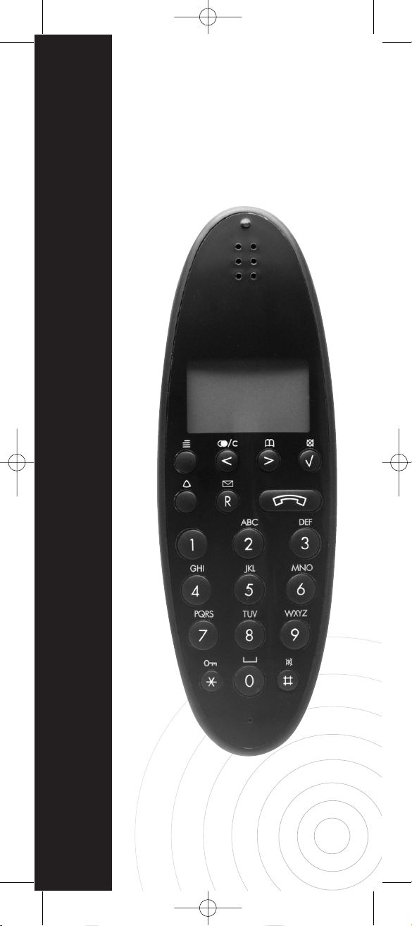
1 Diagostic handset
2 Charger
3 Deployment
4 Subscription of the Handset
5 Menu Structure
5.1 Best Base Stations
5.2 Cur. Base
5.3 Free Chan.
6 Possible Use of the Handset
1. The Diagnostic handset – The professional diagnostic tool for fault finding and deployment of DECT
systems
Finding and correcting faults in a business DECT system is a demanding task.
In order to make sure that you get to the
real problem, you have to be able to see
and control the interference that will exist
in a radio system transmitting in lowpower mode. The Diagnostic handset
contains various features which simplify
fault finding in existing DECT solutions
and the system is adjusted with an
accuracy, that makes it a highly recommendable tool for setting up new DECT
installations.
1415 0200-ed2:14473_KT_1415 0200 ed1 06-12-2007 15:2
Page 3

During normal operation, it takes approximately 3 1/2 hours to charge the handset from fully discharged to its full capacity. Place the handset in the charger.
When the handset is turned on, the display shows the charging status in line 3.
For correct charging be sure the room
temperature is between 0°C and 25°C.
Do not place the handset in di rect sunlight. The battery has a built-in heat sensor
which will stop charging if the battery
temperature is too high.
It is necessary to recharge the battery
when the display shows “BATTERY
LOW”, or if it can not be turned on. The
LED flashes at a low frequency while
charging and lights constantly when the
charging is finished. The display goes
back to normal mode when fully charged.
When the handset is placed in the charger it will not vibrate, and B-answer is
inactive. If the battery is fully dis char ged,
up to 10 min. may pass before charging
begins and the handset can be turned
on. When the charger begins the charging, status is shown in the 3rd line of
the display and the LED flashes slowly.
3
1415 0200-ed2:14473_KT_1415 0200 ed1 06-12-2007 15:2
Page 4

3. Deployment
The difficult part of installing a DECT
system is the question of where to place
the base stations. The placement of the
base stations is made during deployment
of the site. Deployment should only be
performed be trained technicians.
4. Subscription of the Handset
Follow the instruction of your DECT
system.
4
1415 0200-ed2:14473_KT_1415 0200 ed1 06-12-2007 15:2
Page 5

5
1415 0200-ed2:14473_KT_1415 0200 ed1 06-12-2007 15:2
Page 6

6
1415 0200-ed2:14473_KT_1415 0200 ed1 06-12-2007 15:2
Page 7

7
1415 0200-ed2:14473_KT_1415 0200 ed1 06-12-2007 15:2
Page 8

8
5.1. Best Base Stations
In the “BEST BASES” menu it is possible to see how many base stations there
are in the air where the handset is placed. The base stations are sorted after
signal strength (RSSI).
In the RFPI/MASK menu the RFPI number is selected. The RFPI number is a
combination of the ARI and the RPN
(base number) in hex.
The handset can save information for 25
base stations.
ARI
The ARI number is a unique number for
each DECT system. There are 5 different classes: A, B, C, D, and E.(ETS 300
175-6)
Class A is for Home DECT:
Class B is for Business DECT:
ARI A
ARC ARD
A EMC FPN
3 16 17 = 36 bits
RFPI A
E PARI RPN
Y/N A EMC FPN RPN
1 3 16 17 3 = 40 bits
ARI B
ARC ARD
B EIC FPN FPS
3 16 8 4 = 31 bits
1415 0200-ed2:14473_KT_1415 0200 ed1 06-12-2007 15:2
Page 9

Class C is for DECT local loop:
Class D is for DECT directly attached to
GSM:
Class E is for PP to PP direct communication:
9
ARI D
ARC ARD
D GOP FPN
3 20 8 = 31 bits
ARI E
ARC ARD
E FIL FPN
3 16 12 = 31 bits
RFPI D
E PARI NO
Y/N D GOP FPN RPN
1 3 20 8 8 = 40 bits
RFPI B
E PARI RPN
Y/N B EIC FPN FPS RPN
1 3 16 8 4 8 = 40 bits
RFPI C
E PARI RPN
Y/N C POC FPN FPS RPN
1 3 16 8 4 8 = 40 bits
ARI C
ARC ARD
C POC FPN FPS
3 16 8 4 = 31 bits
1415 0200-ed2:14473_KT_1415 0200 ed1 06-12-2007 15:2
Page 10

EMC: Equipment Manufacturer’s Code
FPN: Fixed Part Number
RPN: Radio Fixed Part Number (Base
number)
EIC: Equipment Installer’s Code
FPS: Fixed Part Sub Number
POC: Public Operator Code
GOP: GSM Operator Code
FIL: Fill bits fixed 16-bit 0101... pattern
The ARI Number of a DECT System
The ARI number of a residential system
characterised by the octal number starting with 0.
• Divide the octal number by 2.
The ARI number of a business system is
characterised by the octal number starting with 0.
• Divide the octal number by 4.
The reason to this is because of an
ARI- Bs 31 bits have to be converted
into a 10 digit hex number (ETSI 300
175-6).
• After the division a convert into a hex
number is maked.
i.e.
10002001630o ➾ 100200E6h
To be able to write the hex values A B C
D E F you have to press the keys 1 2 3 4
5 6 down respectively. The keys will toggle between the value every 1.5 seconds.
10
RFPI E
E PARI NO
Y/N E FIL FPN RPN
1 3 16 12 8 = 40 bits
1415 0200-ed2:14473_KT_1415 0200 ed1 06-12-2007 15:2
Page 11

Base Number (RPN)
The RPN value can be read in the handset and can be in decimal or hex value.
The hex value is read in the test mode
* 99989 *, and the decimal value is in the
test mode * 99981 *.
MASK
MASK is shown in decimal and tells how
many bits the handset has to consider in
the RFPI number.
i.e.
RFPI = 100200E606h ➾
0001 0000 0000 0010 0000 0000 1110 0110
ARI
0000 0110b
RFP
If the MASK value is 00 the handset will
look for all base stations in all the DECT
systems in the area.
If the MASK value is 32 it is only the ARI
number, which will be taken into consideration, and the handset will look for all
base stations in the system.
If the MASK value is 40 the handset will
look for only one base station in one
system.
When the RFPI/MASK value is entered
the handset will scan for base stations
each time the handset finds a new base
stations. When a base station changes
place in the index, a tone is generated.
The base stations are sorted after the
po wer in the index. It is possible to change between the base stations with the ar rows
(Please refer to the menu structure).
11
1415 0200-ed2:14473_KT_1415 0200 ed1 06-12-2007 15:2
Page 12

XXXXXXXXXX: RFPI number.
YY: Index (1 - 25).
ZZ: Number of bases found
(1 - 25).
QQ: RSSI value (-99 - 00).
To select a base station press ENTER
and the handset will stay on this base
stations until the handset is powered off
or a LOGIN is made. The display is now
the same as if CUR BASE (Ch. 5.2) was
selected.
5.2 Cur. Base
“Cur Base” makes it possible to see the
status of the base station the handset is
presently locked onto (Se MENU Structure)
XXXXXXXXXX: RFPI number.
F: The frequency the hand-
set is presently using
(0-9).
S: The timeslot the hand-
set is presently using
(0-11).
Q: Bit error measurement
(0-64).
R: RSSI value (-99-00).
The GAP standard has 10 frequencies
from 1880 MHz. to 1900 MHz. in 1.7
MHz steps. For each frequency there are
12 slots. This means that there are 120
channels available.
The US DECT standard has 5 frequencies from 1920 MHz to 1930 MHz. This
means that there are 60 channels
available.
When a handset is in idle mode (no
calls) the handset has a dummy bearer
connected to the base station. The dum-
12
1415 0200-ed2:14473_KT_1415 0200 ed1 06-12-2007 15:2
Page 13

my bearer only uses one channel on the
base station RF-module if the dummy
bearer is jumping between the channels.
When a call is on the base station all
slots on the frequency are blocked. The
frequency on which the call is can also
change, but this only happens if the quality is getting very bad.
5.3 Free Chan.
With “Free Chan” it is possible to see
how many free DECT channels there are
on the spot on which the handset is
located. The channels are sorted after
the power. (Please refer to the Menu
Structure).
YY: Free channel level in steps of
5 dBm from –90 dBm to –60 dBm
XXX: Number of free channels
6. Possible use of the Handset
Deploying a New Site.
When installation has to be made in a
new site the placement of the base stations has to be located. The Deployment
handset can be used for this purpose.
Subscribe the handset to a deployment
base and find the radio coverage from
the base station. When the deployment is
completed the base stations can be put
up. It is possible to download an application note about deployment from the
Internet.
Checking an Installed System
• It is possible to find the range of a base
station in a multi cell system by logging
the handset to a base station.
• There may be some spots on the site
that may cause problems, the so-called
“Hot Spots”. It is possible to locate the-
se spots because the handset registers
4 base stations.
13
1415 0200-ed2:14473_KT_1415 0200 ed1 06-12-2007 15:2
Page 14

Note:
14
1415 0200-ed2:14473_KT_1415 0200 ed1 06-12-2007 15:2
Page 15

15
1415 0200-ed2:14473_KT_1415 0200 ed1 06-12-2007 15:2
Page 16
1415 0200-ED 2
1415 0200-ed2:14473_KT_1415 0200 ed1 06-12-2007 15:2
 Loading...