

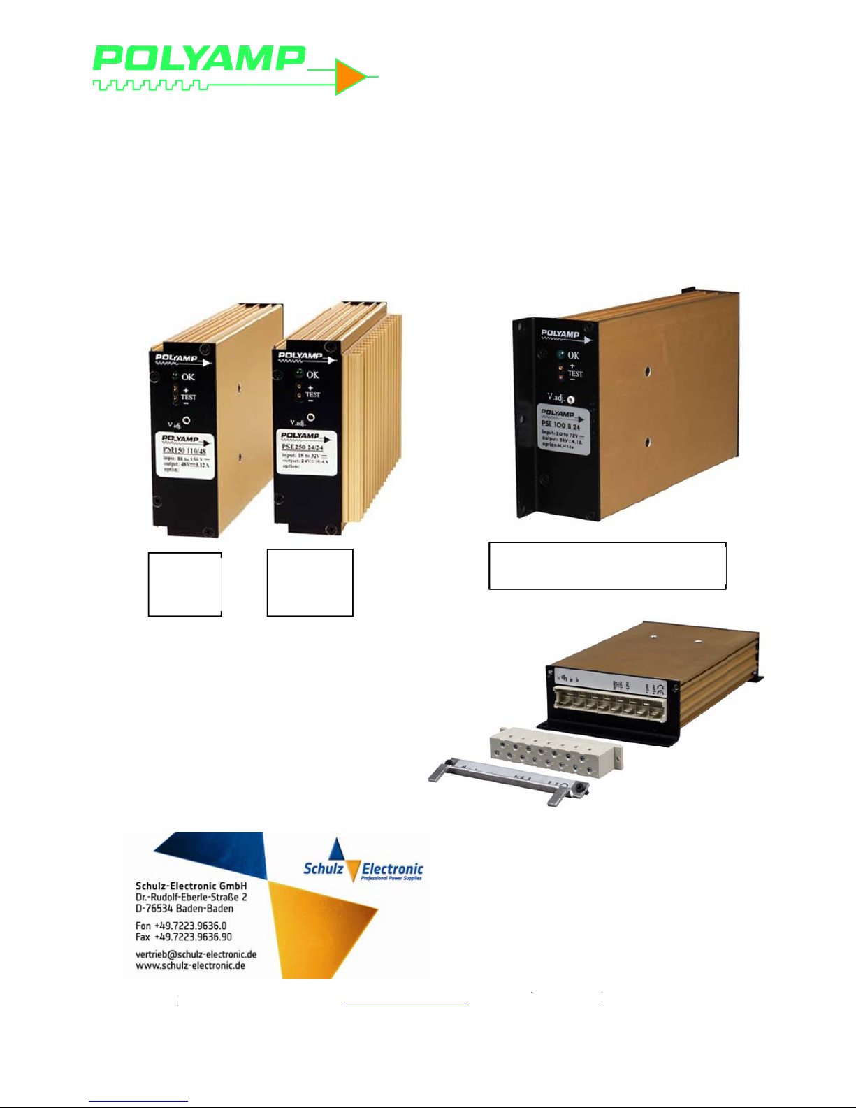
Polyamp PSE Series, PSE100, PSE100AC24, PSE60, PSE60ACW12 Installation Manual
Polyam
p
Box 92
5
191 29
Swede
n
P
SPS
p AB
SOLLENT
U
E60
E100
NA
I
nAC
Optio
n
www.p
info@
p
Tel: +4
Tel: +4
stall
a
/DC
p
PSE
6
T3
olyamp.co
m
olyamp.se
6 8594693
0
6 8594693
0
tion
M
owe
r
0, P
S
E
U
D
U
0 C
A
5 N
C
PSE
chas
anu
a
supp
E100
M
a
VAT no S
E
NS no 35-
4
GE S4231
AGE S423
with optio
n
is mounti
n
l
lies
nual PSE-
A
E5561032
7
30-3372
1
N wall D
I
g
H15
-
Con
n
opti
o
C.docx
6301
N and
S connect
o
ector hold
e
n N
r for
2011-04-
All Po
l
work
m
We wi
warra
n
specif
i
This
m
Howe
v
reserv
e
The e
x
to pre
s
accom
p
The li
g
alert t
h
enclos
u
shock
t
To pre
parts i
n
We s
u
26
lyamp D
C
anship.
T
ll repair
o
ty period
.
cation.
anual is
a
er, the in
s the rig
h
clamatio
n
ence of i
m
anying.
htning fl
a
e user to
p
re that
m
o person
s
vent the r
i
side. Re
f
pply a se
p
re
fe
/DC con
v
his warra
n
r replace
p
The war
r
s comple
t
formatio
n
t to mak
e
point wi
t
portant
o
sh with
a
resence
o
ay be of
s
.
sk of ele
c
er servici
n
arate dec
rs to the
L
Co
p
W
erters ar
e
ty is val
i
roducts
w
anty is v
a
M
e and act
u
may hav
e
changes
i
hin an e
q
perating
a
rrowhead
f uninsu
l
ufficient
m
tric shoc
k
g to qua
l
laration o
ow volt
a
yright 2000-
2
arra
n
warrant
e
d for 24
m
hich pro
lid only i
anu
a
al as pos
been up
d
n this m
a
uilateral
t
nd main
t
, within a
n
ated ”da
n
agnitud
e
Caution
!
, do not
o
ified serv
f confor
m
ge direct
i
INSTAL
PSE seri
e
011
ty
d against
onths fr
o
ve to be
d
f the con
v
l
sible at t
h
ated sin
c
nual with
o
riangle is
enance in
equilate
r
gerous v
o
to const
i
pen encl
o
ice perso
n
ity withi
n
ve and E
M
ATION
M
s AC inp
u
defective
m the da
t
efective
d
erter is u
s
e time of
p
e then. P
o
ut notic
e
intended
t
structions
al triangl
ltage” wi
t
tute a ris
k
sure. No
nel only.
our ship
m
C direct
ANUAL
ts
P
material
a
e of deliv
uring the
ed withi
n
printing.
lyamp A
B
.
to alert th
in the lit
e
e, is inte
n
hin the p
r
of elect
r
serviceab
ent that
m
ive.
age 2(13)
nd
ery.
e user
rature
ded to
oducts
ic
le
ainly

INSTALLATION MANUAL
PSE series AC inputs
2011-04-16 Copyright 2000-2011 Page 3(13)
CONTENT
1 Before installation .............................................................................................................. 4
1.1 Cable and pin dimensioning ..................................................................................... 4
1.2 Inrush current limit .................................................................................................. 4
1.3 Input Fuse ................................................................................................................. 4
2 Installation .......................................................................................................................... 5
3 Parallel connection ............................................................................................................. 6
3.1 Series diode on the output, option C ........................................................................ 6
3.2 Series diode with series resistor, option CR ............................................................ 6
3.3 Output under voltage alarm ..................................................................................... 6
3.4 Connecting systems in N+1 configuration ............................................................... 7
3.5 Connecting converters in parallel on the output ...................................................... 7
3.6 Adjusting output voltage when units are paralleled on the output ........................... 8
4 Multiple loads at the output ................................................................................................ 8
4.1 Short circuits ................................................................................................................ 8
5 Output voltage sense, option S. ......................................................................................... 9
6 Output over voltage protection OVP .................................................................................. 9
6.1 Standard feature ....................................................................................................... 9
6.2 OVP option A .......................................................................................................... 9
7 Output low voltage alarm ................................................................................................... 9
7.1 Logic signal alarm .................................................................................................. 10
7.2 Relay output alarm, option B ................................................................................. 10
8 Higher isolation voltage, Option E2 ................................................................................. 10
9 Isolation voltage test ......................................................................................................... 11
9.1 DC isolation test output to case ............................................................................. 11
9.2 AC isolation test output to case, option E2 ............................................................ 11
9.3 DC isolation test input to output and input to case ................................................ 12
9.4 AC isolation test input to output and input to case ................................................ 12
10 Trouble shooting .............................................................................................................. 13
10.1 There is no output voltage .................................................................................. 13
10.2 Fault report ......................................................................................................... 13

INSTALLATION MANUAL
PSE series AC inputs
2011-04-26 Copyright 2000-2011 Page 4(13)
1 Before installation
Before installation, please read this section
and minimum section 2. This installation
manual shall also be read together with the
datasheet of the product. Download the
datasheet from www.polyamp.com and check
the File archive where in section Datasheet
you will find PSE100AC.pdf .
If any problem occurs during installation
please check section 10 Trouble shooting.
The product is labelled as below example:
The power supply type name consists of
model name PSE60 and PSE100 followed by
input code and output voltage. Two examples:
• ”Type: PSE100AC24” has input
code ”AC” and nominal output
voltage 24 Vd.c.
• ”Type: PSE60ACW12 ” has input
code ”ACW” and nominal output
voltage 12 Vd.c.
The Options are block letters separated by
comma(,). You will find explanation within
this manual what the letter code means.
The input states the nominal input voltage
and maximum input current at any
conditions. It means the output is adjusted
+10% above nominal voltage and close to the
current limit, which is the stated output
current +5% and a lowest input voltage level.
Input range is the input range that the unit
can operate normally.
Output indicates the nominal output voltage
and the rated current.
The output is current limited with a so
called rectangular characteristic. When the
current limit is reached, which is adjusted to
+5% of above mentioned nominal output
current, this is the maximum current that will
continuously flow. The output voltage drops
very quickly down towards zero volt (depends
on the series resistance of the load circuit as
the unit can be regarded as a constant current
generator at over current condition). We have
no time limit on over current condition.
Temperature range is the rated operation
temperature at 100% load condition.
Input, output and case are galvanically
separated from each other.
This is a Class I insulation system, which is
dependent of correct earth connection on the
input. All outputs are insulated from case with
minimum 2000 Vd.c.
Series number is stamped on the panel under
the connector
1.1 Cable and pin dimensioning
The PSE series is using a DIN 41621 H15
connector intended for 3HE Euro format
mounting. Each pin has a continuous current
rating of 15 A @+55°C and 12 A @+70°C
ambient temperature.
The Uout pins are internally parallel
connected and can therefore supply more
current or two different loads. If the unit is
equipped with sense option S this must be
connected to one of the loads or a distribution
point.
1.2 Inrush current limit
The input capacitors are charged through
an NTC resistor to reduce the input
current during start up. All models has an
”output soft start” that do not increase the
input current above the unit rated current
during start up (approx. 0.1s).
1.3 Input Fuse
There is a fuse inside the the power
supply. If that fuse blows it’s an indication
of a fault in the unit. Replace with new
unit and send it back for repair, see
section 10.
PSE100AC24
Input range: 176-264Va.c. 0.71 A
AC frequency: 48-420Hz
Output: 24 Vd.c. 4.2 A
Option: L, C
 Loading...