


Polyam
p
Box 92
5
191 29
Swede
n
p AB
SOLLENT
U
PS
C
P
&
NA
I
nAC
80,
P
SC80, PS
C
PSC150
www.p
info@
p
Tel: +4
Tel: +4
stall
a
/DC
P
SC1
0
100
olyamp.co
m
olyamp.se
6 8594693
0
6 8594693
0
tion
M
owe
r
0, P
S
PSC2
4
PSC1
5
E
U
D
U
0 C
A
5 N
C
anu
a
supp
C150
0 &
0 with T3
M
a
VAT no S
E
NS no 35-
4
GE S4231
AGE S423
l
lies
, PSC
nual-PSC-
A
E5561032
7
30-3372
1
240
C.docx
6301

2011-04-
All
P
wor
kWewarThHow
The e
x
to pre
s
The li
g
al
e
pro
d
To
p
We s
u
26
olyamp
D
manship.
will rep
a
r
ranty pe
r
is manua
l
ever, th
e
reserves
clamatio
ence of i
m
htning fl
rt the us
e
ucts encl
o
revent t
h
parts i
n
pply a se
p
re
fe
C/DC c
o
This war
r
ir or repl
a
iod. The
w
is as co
m
informat
the right
n point w
i
portant
o
ash with
a
r to prese
n
sure that
e risk of
e
side. Ref
e
arate dec
rs to the
L
Co
p
W
nverters
a
anty is v
a
ce produ
c
arranty i
s
p
M
plete an
d
i
on may
h
to make
c
thin an e
q
perating
ac
rrowhea
d
ce of un
-
may be o
f
electri
c
lectric sh
o
r servici
n
laration o
ow volt
a
yright 2000-
2
arra
n
re warra
n
lid for 2
4
ts which
s valid o
n
ecificati
o
anu
a
actual as
ave been
hanges i
n
uilateral
and main
t
company
i
, within
a
insulated
sufficie
n
shock to
Caution
!
ck, do n
o
g to qual
i
f confor
m
ge direct
i
INSTAL
PSC seri
011
ty
ted again
months
f
prove to
b
ly if the
c
n.
l
possible
a
updated
s
this man
u
triangle i
s
enance i
n
ng
n equilat
e
”danger
o
t magnit
u
persons
t open e
n
fied servi
ity withi
n
ve and E
M
ATION
M
s AC inp
u
t defecti
v
om the d
e defecti
v
onverter i
t the tim
e
ince then.
al witho
u
intended
struction
s
ral triang
l
us voltag
e
de to con
s
closure.
N
e person
n
our ship
m
C direct
ANUAL
ts
P
e materi
a
ate of del
i
e during
s used wi
t
of printi
Polyam
p
t notice.
to alert t
h
in the lit
e, is inte
n
” within
t
titute a r
i
o servic
e
el only
ent that
m
ive.
age 2(14)
l and
very.
the
hin
g.
AB
e user
rature
ded to
he
sk of
able
ainly

INSTALLATION MANUAL
PSC series AC inputs
2011-04-26 Copyright 2000-2011 Page 3(14)
Content
1 Before installation ............................................................................................................ 4
1.1 Cable and pin dimensioning ..................................................................................... 4
1.2 Input fuse ................................................................................................................. 4
1.3 Inrush current limit .................................................................................................. 4
2 Installation ........................................................................................................................ 5
3 Several output voltages .................................................................................................... 6
4 Parallel connection ........................................................................................................... 6
4.1 Series diode on the output, option C ............................................................................ 6
4.2 Series diode with series resistor, option CR ................................................................. 7
4.3 Output under voltage alarm ..................................................................................... 7
4.4 Connecting systems in N+1 configuration ................................................................... 7
4.5 Connecting converters in parallel on the output ........................................................... 7
4.6 Adjusting output voltage when units are paralleled on the output ............................... 8
5 Multiple loads at the output ............................................................................................ 9
5.1 Short-circuits ............................................................................................................ 9
6 Output voltage sense, option S. ..................................................................................... 10
7 Output over voltage protection OVP ............................................................................ 10
7.1 Standard feature ..................................................................................................... 10
7.2 OVP option A ........................................................................................................ 10
8 Output low voltage alarm .............................................................................................. 10
8.1 Logic signal alarm .................................................................................................. 10
8.2 Relay output alarm, option B ................................................................................. 10
9 Higher isolation voltage, option E2 ............................................................................... 11
10 Insulation voltage test .................................................................................................... 12
10.1 DC isolation test output to case .......................................................................... 12
10.2 AC isolation test output to case, option E2 ........................................................ 12
10.3 DC isolation test input to output and input to case ............................................ 13
10.4 AC isolation test input to output and input to case ............................................ 13
11 Trouble shooting ............................................................................................................. 14
11.1 There is no or wrong output voltage .................................................................. 14
11.2 The input fuse blows when the input is connected ............................................. 14
11.3 Fault report ......................................................................................................... 14

INSTALLATION MANUAL
PSC series AC inputs
2011-04-26 Copyright 2000-2011 Page 4(14)
1 Before installation
Before installation, please read this section and
minimum section 2. This installation manual
shall also be read together with the datasheet of
the product. Download the datasheet from
www.polyamp.com and check the File archive
where in section Datasheet you will find
PSCAC.pdf.
If any problem occurs during installation
please check section 11 Trouble shooting.
The product is labelled as below example:
The power supply type name consists of model
name PSC80, PSC100, PSC150 and PSC240
followed by input code and output voltage.
Two examples:
• ”Type: PSC240AC24” has input
code ”AC” and nominal output
voltage 24Vd.c.
• ”Type: PSC100ACW5” has input
code ”ACW” and nominal master
output voltage 5 Vd.c.
The Options are block letters separated by
comma(,). You will find explanation within
this manual what the letter code means.
The input states the nominal input voltage and
maximum input current at any conditions. It
means the output is adjusted +10% above
nominal voltage and close to the current limit,
which is the stated output current +5% and a
lowest input voltage level.
Input range is the input range that the unit can
operate normally.
Output indicates the nominal output voltage
and the rated current.
The output is current limited with a so called
rectangular characteristic. When the current
limit is reached, which is adjusted to +5% of
above mentioned nominal output current, this
is the maximum current that will continuously
flow. The output voltage drops very quickly
down towards zero volt (depends on the series
resistance of the load circuit as the unit can be
regarded as a constant current generator at over
current condition). We have no time limit on
over current condition.
Temperature range is the rated operation
temperature at 100% load condition.
Input, output and case are galvanically
separated from each other. This is a Class I
Insulation system, which is dependent of
correct earth connection on the input. All
outputs are insulated from case with minimum
2000 Vd.c.
Series number is stamped on the panel under
the connector
1.1 Cable and pin dimensioning
The PSC series is using a DIN 41621 H15
connector intended for 3HE Euro format
mounting. Each pin has a continuous current
rating of 15 A @+55°C and 12 A @+70°C
ambient temperature.
The U1 pins are internally parallel connected
and can therefore supply more current or two
different loads. If the unit is equipped with
sense option S section 6, the sense must be
connected to one of the loads or a distribution
point.
1.2 Input fuse
The input fuse is rated as below
Input
code
PSC80 PSC100 PSC150 PSC240
AC 2 A 2 A 2 A 2 A
ACR --- 4 A 4 A 4 A
ACW 4 A 4 A 4 A 4 A
Table 1. Input fuses used.
PSC240AC24
Option: L, C
Input: 230Va.c.: 1.26A;
AC frequency: 48-420Hz
Input range: 176-264Va.c.
Output: 24V 10A
Temp range: -25 to +70°C
2011-04-
1.3 I
n
The inp
u
NTC in
r
the inpu
t
All mod
not incr
e
rated cu
r
2 In
s
The con
v
3HE 19
”
only acc
demand
voltage
h
strength
,
With op
t
mount t
h
or with
o
TS35. T
h
in order
a free ai
r
possible
,
fan. On
5
tempera
t
ambient
called T
3
lower te
m
tempera
t
not hav
e
Note th
a
dependa
10°C th
a
expecte
d
therefor
e
and if p
o
To meet
enclose
d
twisted-
p
alarm. S
h
If the co
recomm
e
motor p
o
26
rush cur
r
t capacitors
ush current
l
inrush curr
e
els has an ”
o
ase the inp
u
rent during
tallatio
n
erter is des
i
sub rack u
n
essible for s
e
of EN6095
0
azard prote
c
shall be us
e
ion N, wall
e converter
ptional mo
u
e converte
r
to get suffic
i
around the
, we recom
m
V single o
u
ure might i
n
temperatur
e
, can be pr
o
perature o
r
ure range.
P
this option.
t the expect
e
nt on conve
r
t the tempe
r
life is appr
o
crucial to
c
ssible to re
d
the EMC s
p
”declaratio
n
airs for co
n
hielded cabl
nverter sup
p
nd an exter
n
les to prote
c
ent limit
are charged
imit circuit
t
nt during s
t
utput soft s
t
t current ab
o
start up (ap
p
gned to be
m
it. Otherwis
rvice, whic
h
regarding
fi
tion and m
e
d.
mounting s
e
in any direc
t
nting clips
o
is convecti
o
ent cooling
converter. I
f
end the use
tput voltag
e
creases +20
. An option
a
vided on 5
V
increase th
e
SC150 and
P
d life of the
ter tempera
t
ature is low
e
ximately d
o
ater for goo
d
uce ambien
t
ecifications
of confor
m
necting inp
u
es are not n
e
lies a DC-
m
al parallel
d
t against re
v
Co
p
through an
hat reduces
art up.
art” that do
ve the unit
rox. 0.1s).
ounted in a
e a location
meets the
re enclosur
e
chanical
t you can
ion on a wa
l
n DIN rail
n cooled an
d
there shall
b
this is not
of an extern
the case
°C above
l extra cool
e
versions to
operating
SC240 can
converter is
ure. For eve
r
red the
ubled. It is
ventilation
temperatur
e
in the
ity” use
t, output an
d
cessary.
otor, we
iode at the
erse voltag
e
yright 2000-
2
,
l
e
al
,
y
.
s.
I
n
1
.2.3.
F
F
INSTAL
PSC seri
011
stallation
Check
t
Conne
c
provid
e
and is
r
perfor
m
declara
t
Be aw
a
provid
e
the sen
s
open,
se
Plug in
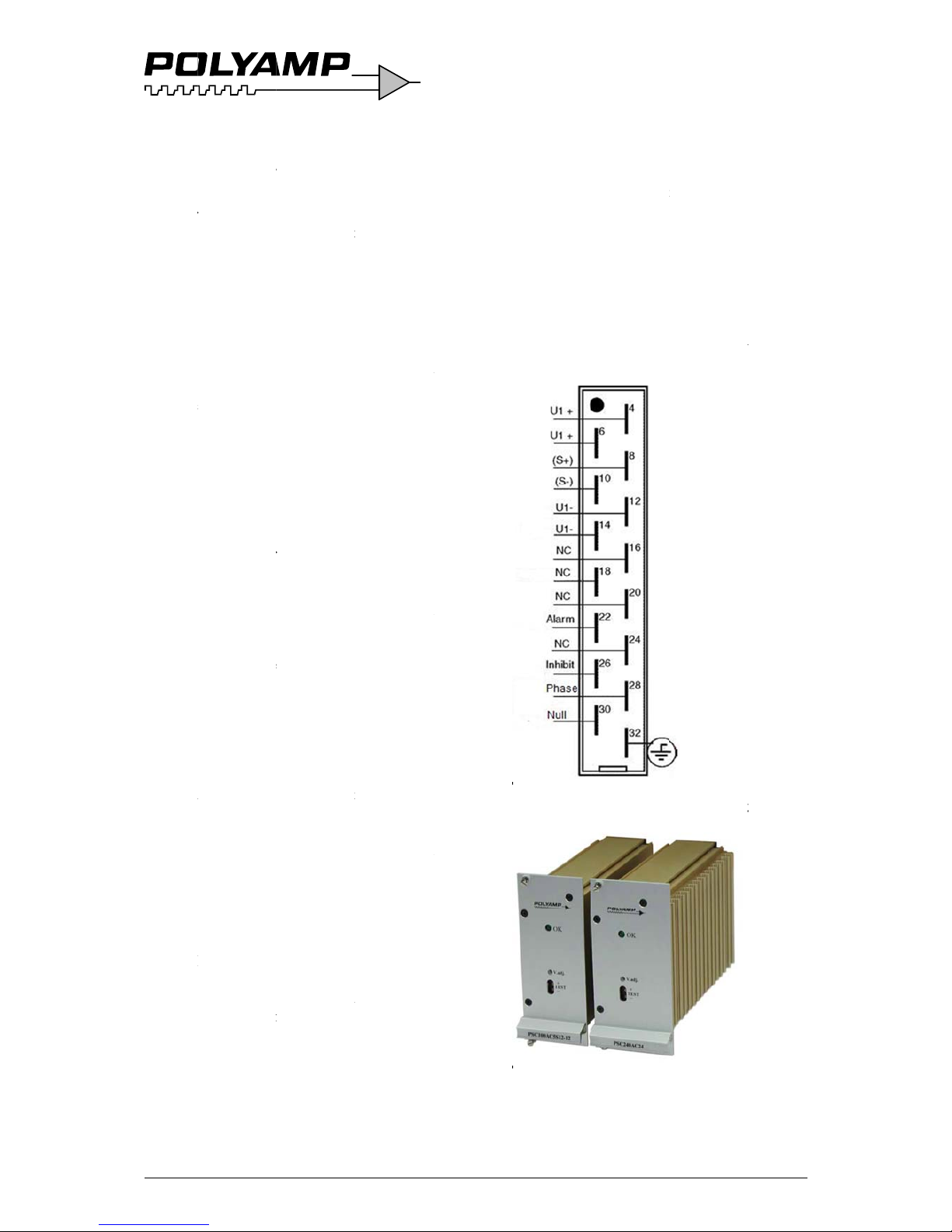
igure 1. Sta
n
on
igure 2. Fr
o
ATION
M
s AC inp
u
in a 3HE
1
he pin-out,
s
t the protect
i
s safety aga
i
quired to a
c
ance accor
d
ion of conf
o
e that if the
d the sense
m
ing point a
n
e sense opt
i
the unit. Go
dard Input
a
DIN41612
H
nt panel opt
i
ANUAL
ts
P
9” Euro s
u
ee Figure 1
ive earth pi
n
nst electric
a
hieve EMC
ing to the
rmity.
sense optio
n
ust be con
n
d cannot be
on S sectio
n
to point 3 n
nd Output
p
15 connec
t
ion L, 10TE
age 5(14)
b rack:
.
32. This
l shock
”S” is
ected to
left
6.
ext page.
in-out
ors.
& 12TE

INSTALLATION MANUAL
PSC series AC inputs
2011-04-26 Copyright 2000-2011 Page 6(14)
Installation with wall mounting panel
option N:
1. Check the pin-out, see Figure 1. Connect
protective earth pin 32. This provides
safety against electrical shock and is
required to achieve EMC performance
according to the declaration of conformity.
2. Connect the output. Be aware that if the
sense option ”S” is provided the sense
must be connected to the sensing point and
cannot be left open, see sense option S
section 6. Bundle the output cables
together, separate from input.
3. The converter output is short-circuit proof
by a constant current limit which works
unlimited in time. Therefore there is no
need to fuse the load (unless you use
multiple loads, see below). The current
limit is fixed to 105% of nominal output
current.
Figure 3. Wall mounting version N.
4. Features and options
• If the converter is to be connected in
parallel at the output, please consult
section 4 Parallel connection on this
page.
• If you use multiple loads, please
consult section 5 Multiple loads at the
output on page 9.
• Check section 7 for the output over
voltage protection page 10.
• If you intend to use alarm feature,
please consult section 8 Under voltage
Alarm on page 10.
5. Connect the input cables. Bundle input
cables together separated from the output
cables.
6. Start the converter by connecting the input
voltage
Beware of hazardous voltages!
The output voltage can be adjusted ±10% of
nominal output voltage with the potentiometer
marked V.ADJ on the front panel. Clockwise
turn increases the output voltage. The
potentiometer has 15 turns. If you have
connected units in parallel on the output, the
procedure of adjusting the output voltage is
described in section 4.6 Adjusting output
voltage when units are paralleled on the output
on page 8.
3 Several output voltages
The PSC series models PSC80, PSC100 and
PSC150 can be supplied with one or two
auxiliary outputs. This manual regards only
single output models. There is a supplementary
manual for two or three outputs.
4 Parallel connection
If a redundant power supply system is
requested, two or more converters can be
connected in parallel. To achieve redundancy
the number of converters must be dimensioned
to carry the whole load even if one converter is
faulty. The option C or CR series diode on the
output must be provided. Connect your load to
the + output after the series diode (cathode).
Another reason for connecting two or more
converters in parallel is to get more power. The
option C must be provided. When the series
diode C or CR option is used the Sense option
S, see chaper 6 page 9, cannot be used.
4.1 Series diode on the output,
option C
A series diode is necessary if the output is
connected in parallel with another power
supply or if you require redundant operation. If
a converter breaks down with an internal shortcircuit on the output and other converters are
connected in parallel on the output, the broken
unit will short-circuit the others if the series
diode is not used. This might cause excessive
heat or even fire in the faulty unit.
The series diode protects the converter output
from external voltage sources.

2011-04-
4.2 Se
r
option
This opt
When s
e
parallel
w
rack, a
b
is provi
d
current
b
The seri
e
describe
special
c
CR opti
o
4.3 Ou
t
If one D
power s
y
detected
The PS
C
provide
contact
o
4.4 Co
config
The
Figu
units fo
r
Each Po
w
(C), bal
a
option
B
With th
e
achieve
d
adjusted
below.
26
ies diod
e
CR
ion is an ext
e
veral PSC
u
ith so call
e
uilt in serie
s
ed that will
etween uni
t
s resistor
w
d in chapter
able arrang
m
n.
put unde
r
C/DC conv
e
stem an ala
r
.
has a logic
a logic sign
a
utput,
s
ee s
e
nnecting
s
uration
re 4 shows
the load an
d
er supply
h
ncing resist
o
. The alarm
CR option
a
if the outp
u
. Use instru
c
with seri
e
nsion of 4.
1
nits are con
n
d “hot plug
i
resistor an
d
automatical
l
s.
ill provide t
h
4.6 and fig
u
ents are ne
e
voltage
a
rter fails in
a
m signal sh
o
open collec
t
l. An optio
n
ction 7 pag
e
ystems i
a N+1 syste
m
one for the
as a built i
n
r (R) and a
l
is cascade c
o
hot plug-i
n
t voltage is
c
tion in
s
ecti
o
Co
p
s resist
o
Series dio
d
ected in
n” in 19” s
u
series diod
e
y balance t
h
e Ud functi
o
re 6. Thus
n
ded with th
i
larm
redundant
uld be
or alarm to
al relay dry
10.
n N+1
with two
redundancy
; series diod
e
arm Relay
nnected.
can be
orrectly
n 4.6 -3
yright 2000-
2
r,
e.
b-
e
n
o
s
.
e
F
4
p
T
honimasteth
l
o
h
a
a
n
F
•
•
INSTAL
PSC seri
011
igure 4. An
Nloa
.5 Conne
c
arallel on
e expected
converter
t
portant fo
r
equal as p
o
mperature.
T
e converter
s
ad. The cab
l
ve a voltag
e
d the load
a
igure 5 and
F
When the
s
recommen
approxim
a
voltage (t
o
temperatu
r
When the
s
not reco
m
b
e approxi
voltage.
ATION
M
s AC inp
u
+1 system
d and one f
o
ting con
v
the outp
u
life of the c
o
emperature.
aralleled u
n
ssible to red
u
o achieve g
must have
s
es should b
e
drop, Ud,
b
t maximum
c
igure 6.
eries diode
i
, the volta
g
ely 1.0% o
f
also compe
n
e coefficien
t
eries diode
i
mended, th
e
ately 0.5
%
ANUAL
ts
P
with two un
i
r the redun
d
erters in
t
nverter is d
e
It is therefo
r
it to share t
h
uce the con
v
ood current
eparate cab
l
dimension
e
etween the
c
current cap
a
is used, whi
c
e drop shou
l
nominal ou
t
sate for th
e
of the diod
e
is not used,
voltage dr
o
of nominal
age 7(14)
ts for the
ancy
pendant
e
e load
erter
sharing
es to the
d to
onverter
city, see
h we
d be
put
negative
).
this is
p should
output

2011-04-
Figure
5
Figure
6
Note th
a
regulati
o
Figure
6
4.6 Ad
j
units
a
1. Con
n
to I
n
usin
g
as
m
con
v
CR
o
2. Me
a
volt
m
hav
e
mus
t
adj
u
26
. Parallel c
o
capacito
r
. Load regu
Ud betw
e
t the voltag
e
n (the volta
g
.
usting o
u
re parall
e
ect and sta
r
stallation o
n
g the series
d
entioned ab
o
erters in pa
r
ption 4.2.
sure the vol
t
eters as sh
o
only acces
s
move it ar
o
stments.
nnection,
w
.
lation with
v
en output a
n
drop affect
s
e at the loa
d
tput volt
a
led on th
e
t all conver
t
page 4. W
e
iode and se
p
ve in 4.4 C
o
allel on the
age at the l
o
wed in
Figu
to one volt
m
und to mak
e
Co
p
ith optional
oltage drop
d load
the load
), see
ge when
output
ers accordin
recommen
d
arate cable
s
nnecting
output or th
e
ad. Connect
re 7. If you
eter you
the
yright 2000-
2
g
e
3
.
F
4
.
5
.
INSTAL
PSC seri
011
To incre
a
Increase t
h
potentio
m
on the un
i
until you
r
load or u
n
increase
a
limit). To
output vo
l
voltage d
i
as in
Figu
Repeat fr
o
output vo
l
igure 7. Adj
u+Tcon
To decre
a
i. Decr
e
the p
o
count
highe
the d
e
the o
u
anym
o
curre
n
highe
volta
g
diode
ii. Repe
a
desir
e
To achie
v
converter
s
b
efore th
e
all units t
h
so that th
e
desired.
ATION
M
s AC inp
u
se the outp
u
e output v
o
eter marked
t with the lo
w
each the de
s
til the outp
u
nymore (as
t
find the uni
t
tage you ca
n
fference be
fo
re 7.
m i. until y
o
tage at the l
o
sting outpu
est or pin 8
nector.
se the outp
u
ase the outp
u
tentiometer
r clockwis
e
t output vo
l
sired voltag
e
tput voltag
e
re (as the o
t
t). To find t
h
t output vo
l
e differenc
e
as in
F
igur
e
t from i. un
t
d output vo
l
e good curr
e
so that the
v
series diod
e
at are conn
e
voltage at t
h
ANUAL
ts
P
t voltage.
ltage by tur
n
”V.ADJ” c
l
west output
ired voltag
e
t voltage do
e
he unit is i
n
with the lo
w
measure t
h
ore the serie
u reach the
ad.
t voltage m
e
on the H15
t voltage.
ut voltage b
y
marked ”V.
A
on the unit
tage until y
o
e at the load
does not de
ther units s
u
he unit with
tage, measu
r
before the
s
e 7.
il you reach
tage at the l
o
nt sharing,
a
voltage diff
e
is 0.00 V b
cted in par
a
he load is st
i
age 8(14)
ing the
ockwise
voltage
at the
s not
current
est
e
s diode,
desired
asure at
turning
DJ”
with the
u reach
or until
crease
ply all
the
e the
eries
the
ad.
djust all
rence
etween
llel and
ll the

2011-04-
5 M
u
If you a
r
fusing t
h
Some c
o
should
b
Figure
8
5.1 S
h
1. If t
h
the
exc
the
the
Th
e
cal
c
if y
o
tro
u
2. If t
h
the
exc
the
unt
iimp
is a
b
res
i
a s
h
3. Lo
n
res
u
blow
Lig
h
in
a
4. To
randapp
tot
a
cap
cap
nee
cal
c
foll
26
ltiple lo
a
e using sev
e
em separat
e
nsideration
s
e taken.
. Connectin
g
ort-circu
ere is a sho
r
total curren
t
eed 105%
o
converter (s
e
output volta
time for th
e
ulated from
ou know th
e
gh the fuse.
ere is a sho
r
total curren
t
eed 105%
o
converter, t
h
l the fuse is
edance of t
h
rupt or me
r
stance of th
e
ort circuit
w
g cables re
d
lting in lon
g
n and hen
c
ht overload
d
blown fuse
.
educe the v
if any bran
c
roximately
3
l output cur
r
acitor is rec
o
acitor will s
u
ded to blow
ulate the ca
p
owing form
u
ds at th
ral loads, w
e
ly with fast
a
regarding s
h
multiple l
o
its
circuit in
o
in all branc
h
f the nomin
a
e label on
fr
ge will not
b
fuse to blo
w
the data sh
e
short circui
t
circuit in
o
in all branc
h
f the nomin
a
e output vo
l
blown. Dep
e
e short circ
u
ely an overl
o
load cable
s
ill vary.
uce short-ci
r
er delay un
t
e an increas
e
oes not nec
oltage drop
a
h has more
t
0% of the p
ent rating,
a
mmended.
S
pply the pe
a
the fuse, se
e
acitor need
e
la:
Co
p
e outpu
t
recommen
d
cting fuses.
ort-circuits
ads.
ne branch a
n
es does no
t
l current of
ont panel),
e affected.
can be
et of the fus
e
current
ne branch a
n
es does
l current of
tage will dr
o
nding on th
it (whether
i
ad) and the
, the effects
cuit current
s
il the fuse i
s
d voltage d
i
essarily res
u
t short-circ
u
han
ower supply
large exter
n
uch a
k current
Figure 8.
T
d, use the
yright 2000-
2
d
d
p
e
t
of
s,
p.
lt
it
al
o
C
1
.IS
∆
∆
E
x Ythgi
is
=
>
T
h
C
C
l
eco Rch
It
c
i
u
n
a
p
e
vdi
t
oco
INSTAL
PSC seri
011
= 1.2 x ( I
S
2 = Safety
m
= Short-cir
t = Time be
f
sheet on t
h
U = Accept
a
blows.
ample:
ou have a 1
A
e short-circ
u
ves you tha
t
24V, and y
o
∆U=24 x
0
e capacita
n
= 1.2 x ( IS
2.4 = 50,
0
hoose a cap
a
ast 115% of
nverter.
epeat this c
a
oose the hi
g
is sometim
e
rcuit curren
t
known. In
t
pear under
s
en with a l
a
p is critical
i
use a separ
a
nverter sup
p
ATION
M
s AC inp
u
x ∆t ) / ∆U
argin.
uit current
t
ore the fuse
e fuse).
ble voltage
d
fuse with
f
it current is
∆t = 10ms.
u can accep
.1= 2.4V.
ce you need
:
x ∆t ) / ∆U
=
00μF
citance wit
h
nominal ou
t
lculation fo
r
hest capaci
t
s difficult t
o
when the n
a
his case a v
o
ome short-
c
rge capacito
r
n one branc
h
te Power s
u
lying this b
r
ANUAL
ts
P
hrough the
f
blows (see
d
dip before t
h
ast characte
r
10A. The d
a
The output
v
t 10% volta
g
:
= 1.2 x 10 x
a rated vol
t
put voltage
all branche
s
ance value.
estimate th
e
ture of a fa
u
ltage dip m
i
ircuit condi
t
present. If
h it is reco
m
pply or DC
/
ranch.
age 9(14)
use.
ata
e fuse
istic and
ta sheet
oltage
e drop
0.01 /
age of at
of the
and
short-
lt is
ght
ions
a voltage
mended
DC

2011-04-
6 Ou
op
t
The re
m
the regu
l
regulati
o
convert
e
sense le
a
voltage
d
convert
e
voltage
r
Figure
9
The sen
s
respecti
v
The sen
s
system,
d
Figure
9
7 Ou
pr
o
7.1 S
t
In case t
h
output,
a
output v
the con
v
The trig
g
the nom
i
long as
t
26
tput vol
t
ion S.
ote voltage
s
ation at the
n is moved
t
r where the
ds than 3 m
ifference b
e
r should no
t
ange. Use t
w
.
e leads mus
t
e pole, eve
n
e cannot be
escribed in
. Remote se
n
tput ov
e
tection
andard f
e
he regulatio
n
secondary
r
oltage level.
erter output
er voltage i
nal voltage.
he over volt
a
age sen
ense is use
d
load. The v
o
o a point o
u
sense is con
n
is not reco
m
tween the l
o
be larger th
a
isted sense
always be
c
if not used
used in a pa
r
section 4.
se connect
i
r voltag
e
OVP
ature
circuit fail
s
egulation ci
r
The circuit
a
from extern
a
s set to 115
%
The circuit
i
ge conditio
n
Co
p
se,
to improve
ltage
tside the
ected. Lon
g
mended. T
h
ad and the
n the outpu
t
wires, see
onnected to
externally.
alleled
on.
on the
cuit limit t
h
lso protect
s
l voltages.
to 120% o
f
s active as
remains.
yright 2000-
2
er
e
t
e
7
Ausac
tr
v
oThex
o
f
1
1st
tr
8
T
han
be
8
T
hcovoThfrco
F
8
T
hse
is
2
.ThFoco
INSTAL
PSC seri
011
.2 OVP
o
n independ
e
ed as over
v
tivated it s
h
gged OVP
b
ltage.
e circuit pr
o
ternal volta
g
the unit. T
h
5% to 120
%
andard on a
l
gger at ma
x
Outpu
t
e alarm cir
c
d trigger w
h
low -10%
o
.1 Logic
is standard
llector alar
m
ltage, see
F
e voltage s
u
om the con
v
mbined wit
h
igure 10. Al
a
.2 Relay
e alarm ha
s
lectable N
O
insulated fr
o
5 kVa.c.,
see
e relay is r
a
r higher vo
l
ntact Polya
m
ATION
M
s AC inp
u
ption A
nt circuit us
i
oltage prote
ort circuits t
h
y switching
tects the co
n
es as well
a
e OVP trig
g
of the no
m
l 5 V maste
r
. 6.2 V.
low vol
uit monitor
s
en the outp
u
f nominal o
u
signal al
a
feature con
s
in referen
c
igure 10.
pply to the
a
erter output.
the alarm
r
rm pin-out
output al
a
dry contact
, NC functi
o
m both inp
u
Figure 11.
ted 30V 0.5
A
tage/curren
t
p.
ANUAL
ts
P
a
ng a SCR t
h
ction. Whe
n
e output.
R
off and on
t
nverter fro
m
s regulation
er voltage i
s
inal voltage
outputs an
d
tage ala
the output
v
t voltage b
e
tput voltag
e
rm
ist of an op
e
e to the out
p
alarm can b
e
It cannot b
e
elay option.
and voltage
s
rm, opti
o
output with
n. The rela
y
t and outpu
A (a.c. & d.
c
relay ratin
g
ge 10(14)
yristor is
eset a
he input
high
failures
set to
OVP is
will
m
oltage
come
.
n
ut
taken
.
n B
output
.).
please

2011-04-
The alar
m
1. Nor
m
Con
n
fro
m
con
n”NO
2. Nor
m
Con
n
fro
m
con
n”NC
Figure
1
The rela
y
case. Th
(a.c. an
d
9 Hi
gopt
E2 is 2
t
and cas
e
level A.
26
relay can
ally Open
(
ect twisted
-
centre pin
o
ector and c
o
”.
ally Close
d
ect twisted
-
centre pin
o
ector and c
o
”.
1. UL alar
m
s
ymbol
is isolated
e relay can
s
d.c. values)
her isol
ion E2
o 2.5 kVa.c.
. The emiss
i
be connecte
d
NO).
pair (0.25
m
f the remo
v
nnector pin
(NC).
pair (0.25
m
f the remo
v
nnector pin
with intern
shows Alar
m
2500Va.c.
fr
witch maxi
m
.
ation vo
1 minute b
e
on level is i
n
Co
p
in two wa
y
m2 -0.5 m
m
able alarm
marked
m2 - 0.5 m
m
able alarm
marked
al relay. Re
l
state.
om input a
n
um 30V/5
A
ltage,
tween outp
u
crease to
yright 2000-
2
s:
2
)
2
)
ay
d
t
INSTAL
PSC seri
011
ATION
M
s AC inp
u
ANUAL
ts
Page 11(14)

2011-04-
10 In
s
Each co
n
factory
b
consecu
t
capacito
r
the unit.
complet
e
The ins
u
input an
d
case iso
l
E2 can i
n
If your i
s
the AC
c
isolatio
n
1.1 ≈ 40
10.1 D
C
1. Dis
c
2. Con
n
con
v
3. Con
n
4. Con
n
out
p
volt
a
200
0
Vd.
c
not
e
app
l
Y-c
a
5. Tur
n
the
t
betw
An
pe
rdan
26
ulation
v
verter has
b
efore deliv
e
ive insulati
o
rs and affec
t
We ask yo
u
ly avoid su
c
lation volta
g
output, in
p
ation is 2 k
V
crease this
solation test
urrent, you
test with 4
0
00 Vd.c wh
e
W
isolatio
onnect all c
a
ect the inp
u
erter to cas
e
ect the out
p
ect your is
o
ut and case.
ge of the is
o
Vd.c. (Wit
h
.) Check th
a
xceed 5μA.
ied for mor
e
pacitors mi
g
off the isol
a
est voltage
w
een output
a
insulation
t
formed by
p
gers and h
a
oltage
t
een isolatio
n
ry. Please n
o
n test dama
g
the EMC p
e
therefore to
h test.
e is 2.5 kV
a
ut and case.
d.c. on all
m
isolation.
equipment
c
can perform
00 Vd.c (25
re 1.1 = saf
e
arning!
n test out
bles from t
h
t terminals
o
.
ut terminal
s
lation teste
r
See Figure
1
lation teste
r
option E2
0
t the leakag
e
The voltag
e
than a few
s
ht be dama
g
tion tester
a
ith a 10 M
Ω
nd case.
est shall on
l
ersonnel a
w
zards of t
h
Co
p
est
tested in
te that
e the Y-
rformance
o
minimize o
r
.c between
The output
t
odels. Opti
o
annot suppl
y
a DC
00 V x √2 x
ty factor).
put to ca
s
e converter.
f the
together.
between
2. Raise th
e
from 0 to
to 4000
current do
e
should not
b
econds or t
h
ed.
nd discharg
e
resistor
y be
are of the
e test.
yright 2000-
2
f
o
n
e
s
e
e
F
1
Beaoc
1
.2.3.4.5.6.
INSTAL
PSC seri
011
igure 12. O
utes
0.2 AC is
o
case,
eware of t
h
rth curre
n
cur durin
g
Disconne
c
Connect t
h
converter
Connect t
h
Connect
y
output an
d
Raise the
from 0 to
not be ap
p
minute or
damaged.
Turn off
t
the test v
o
between
o
ATION
M
s AC inp
u
tput to case
t.
lation te
s
ption E2
e rather
h
ts (about
1
this test.
t all cables
f
e input ter
m
to case.
e output te
r
our isolatio
n
case. See
F
voltage of t
h
2500 Va.c.
T
lied for mo
r
the Y-capa
c
e isolation
t
ltage with a
utput and c
a
ANUAL
ts
P
a
isolation v
o
t output
t
igh capaci
t
00 mA) t
h
from the co
n
inals of the
minals toge
t
tester bet
w
igure 12.
e isolation
t
he voltage
s
e than one (
itors might
b
tester and di
10 MΩ resi
se.
ge 12(14)
ltage
o
ive
at will
verter.
her.
een
ester
hould
1)
e
scharge
stor

2011-04-
10.3
D
o
u
1. Dis
c
2. Con
n
con
v
3. Con
n
4. Con
n
inp
u
5. Rai
s
fro
m
leak
a
volt
a
tha
n
mig
h
6. Tur
n
the
t
betw
10.4 A
C
o
u
Beware
current
s
during
t
1. Dis
c
2. Con
n
con
v
3. Con
n
4. Con
n
inp
u
volt
a
250
0
app
l
Y c
a
5. Tur
n
the
t
betw
An in
s
perfo
r
dang
e
26
Wa
r
C isolati
o
tput and
onnect all c
a
ect the out
p
erter to cas
e
ect the inp
u
ect your is
o
t and case.
S
e the voltag
e
0 to 4000
V
age current
d
ge should
n
a few seco
n
t be damag
e
off the isol
a
est voltage
w
een input a
n
isolatio
tput and
of the rath
e
(about 10
0
his test.
onnect all c
a
ect the out
p
erter to cas
e
ect the inp
u
ect your is
o
t and case.
S
ge of the is
o
Va.c. The
v
ied for mor
e
pacitors mi
g
off the isol
a
est voltage
w
een input a
n
ulation tes
t
med by pe
r
rs and haz
a
ning!
n test in
p
input to
c
bles from t
h
ut terminal
s
. See
F
igur
e
t terminals
t
lation teste
r
ee Figure 1
3
of the isol
a
d.c. Check
t
oes not exc
e
ot be applie
d
ds or the Y-
d.
tion tester
a
ith a 10 M
Ω
d case.
n test inp
u
input to
c
r high cap
a
mA) that
w
bles from t
h
ut terminal
s
. See
F
igur
e
t terminals
t
lation teste
r
ee Figure 1
3
lation teste
r
oltage sho
u
than one (1
)
ht be dama
g
tion tester
a
ith a 10 M
Ω
d case.
shall only
b
sonnel awa
rds of the t
e
Co
p
ut to
ase
e converter.
of the
13.
ogether.
between
.
tion tester
hat the
ed 5μA. T
h
for more
apacitors
nd discharg
e
resistor
t to
ase
citive eart
h
ill occur
e converter.
of the
13.
ogether.
between
Raise the
from 0 to
ld not be
minute or
t
ed.
nd discharg
e
resistor
e
re of the
st.
yright 2000-
2
e
he
F
i
s
INSTAL
PSC seri
011
igure 13. In
p
olation volt
a
ATION
M
s AC inp
u
ut to outpu
t
ge test.
ANUAL
ts
P
a
and input t
o
ge 13(14)
case

INSTALLATION MANUAL
PSC series AC inputs
2011-04-26 Copyright 2000-2011 Page 14(14)
11 Trouble shooting
11.1 There is no or wrong output
voltage
1. Check that the input fuse is not broken.
2. Check that the input voltage is within the
specified limits.
3. The power supply output may be in current
limit due to excessive output current or an
external short-circuit on the output.
• Measure the output voltage. If shows
> 0.5 V the thyristor OVP, see section
7.2, might have trigged.
• Disconnect the input by an external
voltage breaker.
• Disconnect the load.
• Connect input fuse again and measure
the output voltage. If the converter
now starts the load was too heavy or
there was a short circuit.
• If there is an external short circuit,
remove it.
• If the load is too large decrease the
load or consult your Polyamp dealer.
5. The unit is broken. Contact your Polyamp
dealer.
11.2 The input fuse blows when
the input is connected
1. Change the fuse and switch-on the input
again. If the fuse blows again then the unit
is broken.
2. Contact your Polyamp dealer.
11.3 Fault report
We do not recommend you to repair a faulty
unit. All unit opened by customer will not be
repaired under warranty.
Please use our RMA system from our
webpage www.polyamp.com
Warranty
All Polyamp DC/DC converters are warranted
against defective material and workmanship.
This warranty is valid for 24 months from the
date of delivery. We will repair or replace
products which prove to be defective during
the warranty period. The warranty is valid only
if the converter is used within specification.
Please describe the conditions when the fault
occurred and please return a faulty converter
to:
Your local distributor or:
SWITCH CRAFT S.A.
Bel Air 63
CH-2300 La Chaux-de-Fonds
Switzerland
Tel: +41 32 9678800
Fax: +41 32 9678809
e-mail: info@switchcraft.ch
Latest version of this manual
www.polyamp.com
 Loading...