

Polyamp PC1400, PC1000, PC2000 Installation Manual
PC1000-PC2000 INSTALLATION MANUAL
PC1000 / PC1400 /PC2000
Installation manual
Mailing address Visit/Shipping Telephone Telefax Postalgiro: 68 13 25-7
Box 229
SE-597 25 ÅTVIDABERG
Main residence: Sollentuna http:// www.polyamp.com e-mail: info@polyamp.se VAT.no: SE556103276301
Page 1 (14)
Bäckgatan 10
SE-597 53 ÅTVIDABERG
+46 120 85400 +46 120 85405 Merita NB:
SEB:
10275-8.doc
3259-18-01290
5403-10-05571

PC1000-PC2000 INSTALLATION MANUAL
Warranty
All Polyamp DC/DC converters are warranted against defective material and
workmanship. This warranty is valid for 24 months from the date of delivery.
We will repair or replace products which prove to be defective during the
warranty period. The warranty is valid only if the converter is used within
specification.
Manual
This manual is as complete and actual as possible at the time of printing.
However, the information may have been updated since then. Polyamp AB
reserves the right to make changes in this manual without notice.
The exclamation point within an equilateral triangle is intended to alert the user to presence of
important operating and maintenance instructions in the literature accompanying
The lightning flash with arrowhead, within an equilateral triangle, is intended to alert the user to
presence of un-insulated ”dangerous voltage” within the products enclosure that may be of sufficient
magnitude to constitute a risk of electric shock to persons
Caution!
To prevent the risk of electric shock, do not open enclosure. No serviceable parts inside. Refer
servicing to qualified service personnel only
10275-8.doc
Polyamp AB, Sweden Page 2 (14)

PC1000-PC2000 INSTALLATION MANUAL
CONTENTS
1 BEFORE INSTALLATION...............................................................................................................................4
2 INSTALLATION................................................................................................................................................5
3 PARALLEL CONNECTION ............................................................................................................................6
3.1 SERIES DIODE ON THE OUTPUT ........................................................................................................................6
3.2 CURRENT SHARING .........................................................................................................................................6
3.3 VOLTAGE ADJUSTMENT WITH CURRENT SHARING ...........................................................................................7
4 MULTIPLE LOADS AT THE OUTPUT.........................................................................................................7
4.1 SHORT-CIRCUITS.............................................................................................................................................7
5 ALARM ...............................................................................................................................................................8
5.1 OVER AND UNDER VOLTAGE ALARM ...............................................................................................................8
5.2 OVER TEMPERATURE.......................................................................................................................................8
6 SENSE..................................................................................................................................................................9
6.1 EXTERNAL SENSE............................................................................................................................................9
7 INHIBIT ..............................................................................................................................................................9
8 OUTPUT OVER VOLTAGE PROTECTION.................................................................................................9
9 INRUSH CURRENT LIMIT...........................................................................................................................10
10 ISOLATION VOLTAGE TEST....................................................................................................................10
10.1 DC ISOLATION TEST OUTPUT TO CASE.........................................................................................................10
10.2 DC ISOLATION TEST INPUT TO OUTPUT AND INPUT TO CASE ........................................................................10
10.3 AC ISOLATION TEST INPUT TO OUTPUT AND INPUT TO CASE ........................................................................10
11 MAINTENANCE............................................................................................................................................11
12 TROUBLE SHOOTING................................................................................................................................11
12.1 THERE IS NO OUTPUT VOLTAGE...................................................................................................................11
12.2 THE INPUT FUSE BLOWS WHEN THE INPUT IS CONNECTED............................................................................11
12.3 THE CONVERTER STARTS AND STOPS REPEATEDLY......................................................................................11
12.4 THE CONVERTER STOPS AFTER SEVERAL HOURS..........................................................................................11
12.5 FAULT REPORT............................................................................................................................................ 12
10275-8.doc
Polyamp AB, Sweden Page 3 (14)

PC1000-PC2000 INSTALLATION MANUAL
limit circuit. If reverse voltage occurs at
1 Before installation
Before installation we recommend that you
read this and next section of this manual. If any
problem occurs, consult
If the converter includes a fan, please notice
Maintenance
.
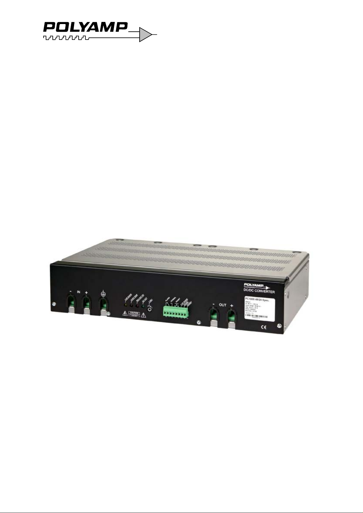
On the front panel label the following is
displayed: Converter type, input voltage range,
nominal output voltage, serial number, options
and article number. The converter type name
consists of model name PC1000, PC1400 or
PC2000 followed by input code and output
voltage. Two examples:
• Type: “PC2000 110/48” has input code “110”
and nominal output voltage 48Vd.c.
• ”Type: “PC1000 24/24” has input code “24”
and nominal output voltage 24Vd.c.
If you intend to parallel connect the output,
please check that option C is supplied. It
means series diode on output.
Input, output and case are galvanically
separated from each other. You can thus
choose how you want the system connected.
The output can be connected with any pole to
protective earth or as a floating output with
max ±150V to the protective earth. It means
that maximum 3 units can be put in series.
The electrical safety system is a class I, which
means that protective earth has to be
connected. The 110 and 220 input code models
can also be used as class II equipment without
protective earth. Although units installed in
dirty environments shall be connected to
protective earth.
On 110 and 220 input code the feeding system
can be defined as Primary circuit (Max
250Va.c.) and as Secondary circuit.
On 24 and 48 input code the feeding system
can be defined as Secondary circuit voltage,
and SELV voltage.
The cables used for input and output feeding
shall be dimensioned to fit the fuse rating and
continuous current as well as intended ambient
temperature range and insulations demand due
to the voltage used.
The input is protected against reverse polarity
by combination circuit with inrush current
12 Trouble shooting.
11
installation the converter will not start. The
reverse voltage will not cause damage to the
unit.
The input shall be fused with an approved fuse
with high breaking capacity. We recommend
following fuses ratings and fuses. Please note
that in installation class I with protective earth,
the fuse shall be on the pole not in connection
with the protective earth.
PC1000 input fuses
Input voltage code Time delay fuse
24 63 A, Siemens 3NA3 022
48 35 A, Siemens 3NA3 014
110 16 A, Siemens 3NA3 005
220 10 A, Siemens 3NA3 003
PC1400 input fuses
Input voltage code Time delay fuse
48 50 A, Siemens 3NA3 020
110 20 A, Siemens 3NA3 007
220 10 A, Siemens 3NA3 003
PC2000 input fuses
Input voltage code Time delay fuse
48 63 A, Siemens 3NA3 022
110 25 A Siemens 3NA3 010
220 16 A, Siemens 3NA3 005
Table 1. Recommended input fuses.
There are two reasons we do not include the
fuse.
1. DC-networks should be fused at the
distribution point to protect the cable.
2. Different applications require different
types of fuses.
To meet the EMC specifications in the
enclosed “declaration of conformity” use
twisted-pairs for connecting input, output,
alarm, inhibit and voltage sense. Shielded
cables are not necessary.
If the converter is mounted in an electric
vehicle, an external series diode on the input is
recommended. Please contact your Polyamp
dealer.
If the converter supplies a DC-motor, we
recommend an external parallel diode at the
motor poles to protect against reverse voltages.
10275-8.doc
Polyamp AB, Sweden Page 4 (14)

PC1000-PC2000 INSTALLATION MANUAL
For the disconnection ability, an external
disconnection device, which is able to
disconnect both polarities, shall be
incorporated with the input power supply cord.
The disconnection device must be properly
labelled and easy accessible.
2 Installation
The converter is supplied with mounting
brackets intended for 19”-rack mounting. The
PC1000 converter is convection cooled and in
order to get sufficient cooling there shall be a
minimum of >30 mm space around the unit
except for the sides. PC1000 is only intended
for horizontal mounting.
PC1400 and PC2000 use an internal fan and
need therefore minimum >30mm space around
the unit except for the sides. The cooling fins
at the rear shall never be covered. The fan
cooled versions can be mounted in any
direction. For mounting plate or chassis
mounting please use the L220-1 brackets.
Note that the expected life of the converter is
dependant on converter temperature. For every
10°C that the temperature is lowered the
expected life is approximately doubled. It is
therefore crucial to cater for good ventilation
and if possible to reduce ambient temperature.
To meet the EMC specifications in the
enclosed “declaration of conformity” use
twisted-pairs for connecting input, output,
alarm, inhibit and voltage sense. Shielded
cables are not necessary.
On 24 and 48 input code the input cables are
individual. On 110 and 220 input code use a
cable cord with external approved insulation
for the Primary circuit and Secondary
hazardous voltage rating.
1. Remove front cover with 4 screws.
On 24 and 48 inputs separate inlets. On 110
and 220 input code put the cable into the
cable inlet and fix it with the cable clamp
after connection. See
connection for 24V and 48V inputs.
2. Cable connection for 110V and 220V inputs.
Figure 1. Cable
2. First connect protective earth in connector
K3 marked with an earth symbol. Then
connect the input.
3. Connect the output. The converter output is
short-circuit proof by a constant current
limit which works unlimited in time.
Therefore there is no need to fuse the load
(unless you use multiple loads, see below).
The current limit is fixed to 105% of
nominal output current.
• If the converter is to be connected in
parallel at the output or if you use
current sharing for equal current sharing,
please consult 3 Parallel connection on
page 6.
• If you intend to use multiple loads,
please consult 4 Multiple loads at the
output on page 7.
• If you intend to use the alarm, please
consult 5 Alarm on page 8.
• If you intend to use output voltage
sense, please consult 6 Sense on page 9.
• If you intend to use inhibit, please
consult 7 Inhibit on page 9.
4. Mount the front cover
5. Start the converter with your external input
disconnection device.
• The output voltage can be adjusted
+10% to -5% of nominal output voltage
with the potentiometer marked V.ADJ
on the front panel. Clockwise turn
increases the output voltage. The
potentiometer has 15 turns. If you are
using current sharing, the procedure of
adjusting the output voltage is described
in 3.3 Voltage adjustment with current
sharing on page 7.
6. When the converter is to be disconnected,
switch-off the input voltage with the
disconnecting unit. Disconnect the input
cables first, then output and last the
protective case connection.
And Figure
10275-8.doc
Polyamp AB, Sweden Page 5 (14)
 Loading...