

Page 1
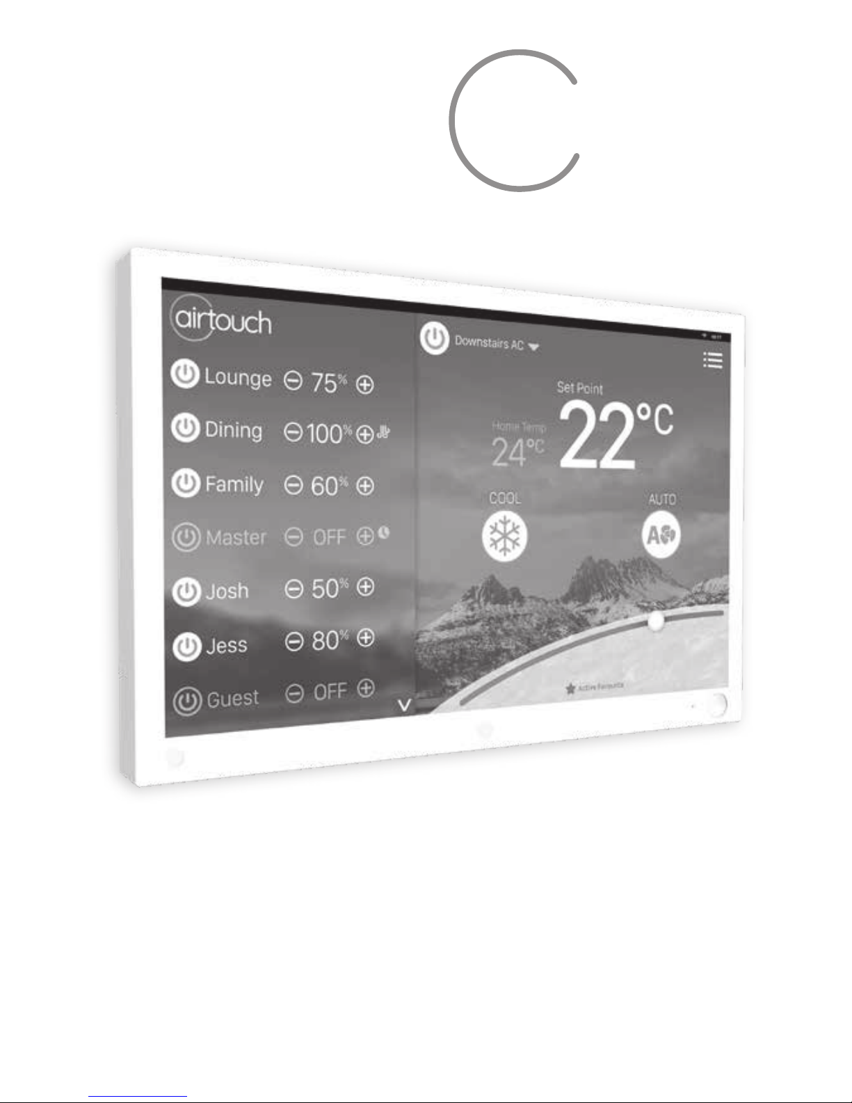
airtouch.net.au
Installer Manual
airtouch
Page 2

Contents
Compatible Brands
4
1. Components
5
2. Conguration
6
3. Pre-Installation
9
4. Components Installation
10
5. Recommended Commissioning Procedure
15
5.1 Parameters
16
5.1.1 Console in Group or for AC control
16
5.1.2 Total Groups in the System
16
5.1.3 Console Address
16
5.1.4 Damper RPM setting
17
5.1.5 Installer Settings Password
17
5.1.6 Reset and Save current system settings
17
5.2 Balancing
18
5.3 Sensors
20
5.3.1 Assign a sensor to a group
21
5.3.2 Pair main module and wireless sensors (ITCs)
21
Liability
Please read the instructions before installing this AirTouch Zoning Control System. Polyaire
Pty Ltd does not accept any responsibility for loss or damage that may occur as a result of
the incorrect installation of this AirTouch Control System.
Page 3

5.3.3 Calibrate a Sensor
21
5.4 Grouping Zones
22
5.5 Choosing Group Temperature Control
23
5.6 Setting Minimum Ventilation
24
5.7 Spill or Bypass
24
5.8 Enabling/Disabling Service Reminder
25
5.9 Setting up AC Control
27
5.9.1 Name AC Units
27
5.9.2 AC Detail Settings
27
5.9.3
Choose AC Control Thermistor
28
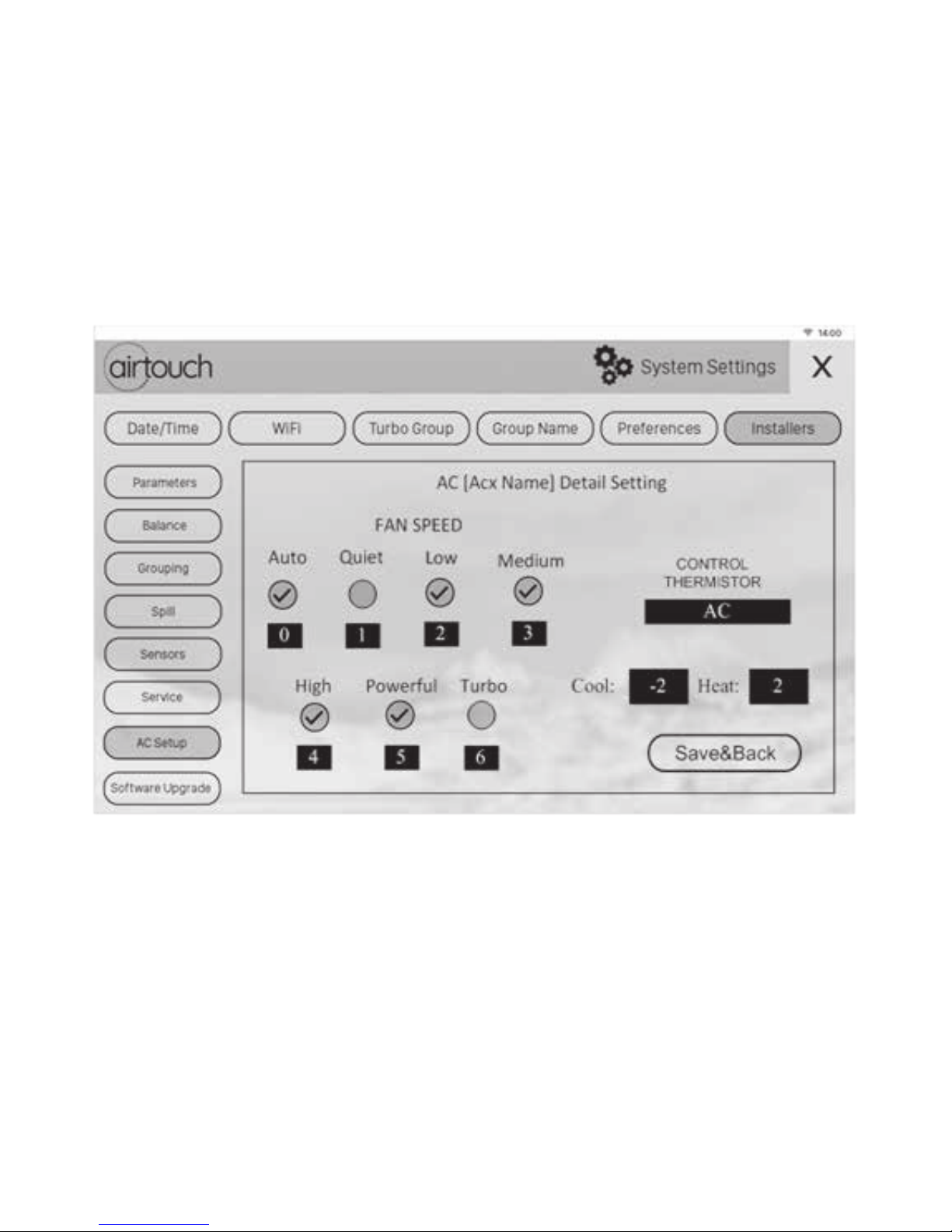
5.9.4 Congure AC Fan Speed Options
29
5.9.5 Control Temperature Oset
29
5.9.6 Multiple Ducted Systems
30
5.9.7 Groups connected in each ducted system
30
5.10 Setting up Wi-Fi connection
31
5.11 Testing Damper On/O
31
5.12 Software Update
32
6. Wiring Diagrams
33
7. Downloading and Installing AirTouch 4 App
63
8. Troubleshooting
64
Page 4

4
Compatible Brands
Compatible Brands
Page 5
5
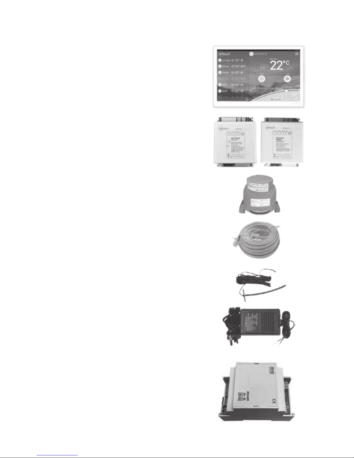
1.1 Console
Users can input control commands from the
console to turn on or o a group/zone or AC.
It is used to input all parameters. The color LCD
displays clock, zone, WiFi, AC, temperature and
other statuses.
1.2 Main Control Module and Extension Module
(optional)
Main control module (8 zones) and its optional
extension module (extra 8 zones) control the
position of motorized damper of each zone.
1.3 Motorized Damper (Bright Green)
Motorized dampers drive the blade of the
damper to adjust the air supply.
1.4 Cables
Cables with left latch or central latch plugs
connect the main control module, extension
module (if applicable), console, and
motorized dampers together.
1.5 Supply Air Sensor (optional)
Supply air sensor measures the temperature of
the supply air for auto mode recognition.
1.6 Power Supply
24VAC transformers provide power to the main
and extension modules.
1.7 AC Gateways (optional)
AC gateways are for full control of most major
brand ducted systems such as Daikin,
Panasonic, Fujitsu, Mitsubishi Electric, Mitsubishi
Heavy Industries, Toshiba, LG, Hitachi, Samsung,
Carrier, Rinnai, Midea, Braemar and Gree. Each
gateway comes with a RS485 cable for
connecting the gateway with AirTouch 4.
1. Components
Components
Page 6
6
1. Components contd.
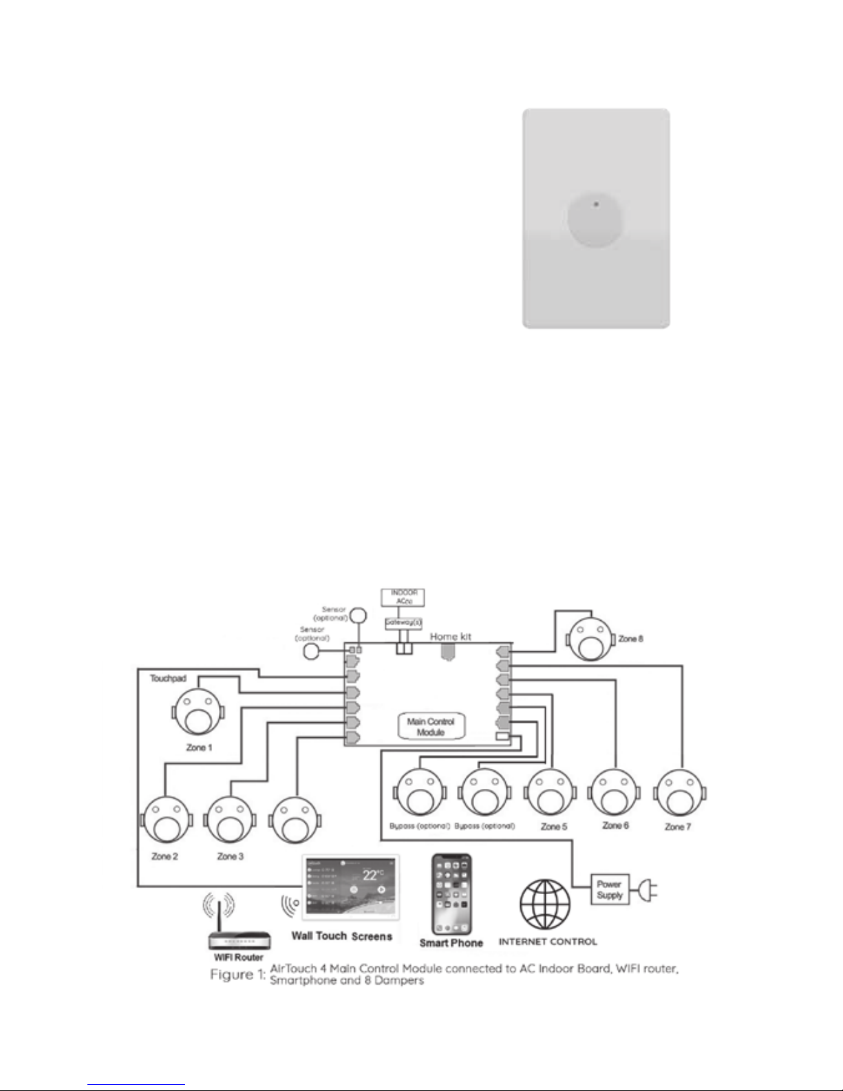
1.8 Wireless temperature sensor
Wireless sensors are used for group
temperature and On/O control. Each group
can have up to two wireless temperature
sensors. The wireless sensors send measured
room temperature or On/O command back
to main module regularly. They are driven by
button type battery and have dipswitches for
their own identication.
2. Conguration
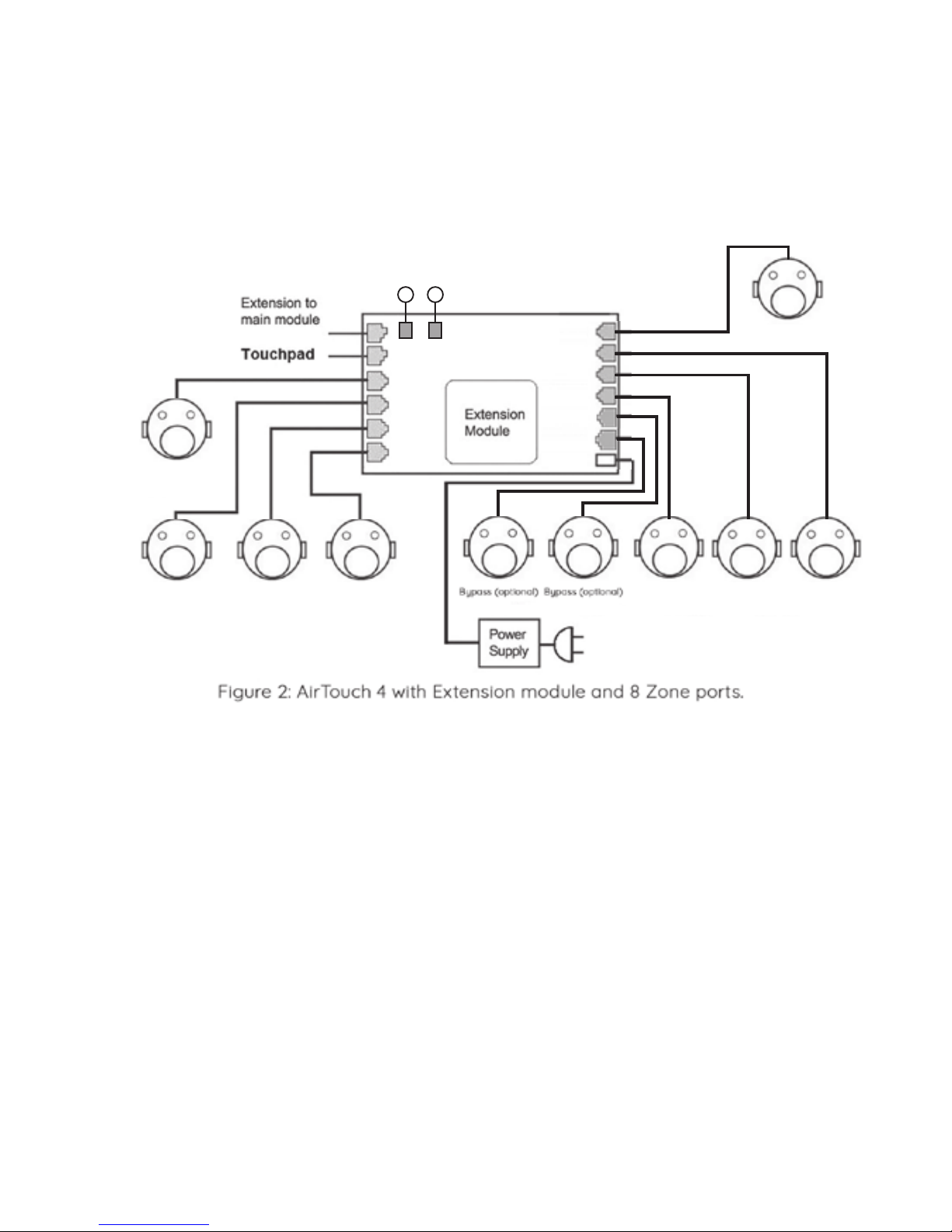
AirTouch 4 System is a star architecture system that allows communications
between AirTouch 4 main control module, extension module, AC unit, WiFi router
(to connect to smart phones and internet), up to 16 zone dampers, wireless
temperature sensors and up to two consoles. Figure below shows the
connection of devices such as the WiFi router, AC indoor PCB, extension module,
two consoles, and eight dampers to the main module.
Components contd. & Configuration
Continued on next page.
Zone 4
Page 7
7
Eight motorized dampers can be connected to the main control module.
Nine dampers and above (up to 16) will need the extension module.
The wiring of the AirTouch 4 system is straightforward. A cable with central latched
plugs connects a motorized damper to the relevant output port clearly marked on
the main or extension module. Figure below shows the connection of eight
dampers to the extension module.
Configuration contd.
If there is another gateway for another AC, it will be connected to Modbus line.
Maximum four gateways can be connected for one AirTouch 4 to control four AC’s.
Please see AC wirings for details in section 6.
Main and extension modules can be in dierent locations and connected via a
cable with left latched plugs on both ends. Console is connected to the ‘T’ port on
main module.
Up to two consoles can be joined in a system. One will be connected to the main
module and the other to the extension module. One screen is set to Master (1) and
the other is set to Slave (2) .
Figure below shows the linking of the main module to the extension module,
AC unit, consoles, wireless sensors and smart phone.
Sensor
(optional)
Sensor
(optional)
Zone 9 Zone A Zone B
Zone A Zone B Zone C
Zone 9
Zone G
B3 B4
Zone FZone EZone D
Page 8

8
Note:
Install the console at least 20mm away from any other wall control to avoid
potential interference.
Configuration contd.
1 Console per board
Unit
gateways
wired in
sequence
24V
24V
Touch Screen 1Home Router
Touch Screen 2
Smart Phones
Main Module
Extension Module
To Zone Dampers
Bypass 2
RS 485
Unit
Gateway
1
A B
Indoor Unit 1 Indoor Unit 2 Indoor Unit 3 Indoor Unit 4
Bypass 1
Supply Air
Sensor
(Optional)
Supply Air
Sensor
(Optional)
Supply Air
Sensor
(Optional)
Supply Air
Sensor
(Optional)
Apple
Homekit
Bypass 4
Bypass 3
To Zone Dampers
Z1
Z2
Z3
Z4
Z8
Z7
Z6
Z5
ZD
ZC
ZB
ZA
Z9
ZE
ZF
ZG
Unit
Gateway
2
Unit
Gateway
3
Unit
Gateway
4
24V
24V
Extension Module
Supply Air
Sensor
(Optional)
Supply Air
Sensor
(Optional)
Bypass 4
Bypass 3
To Zone Dampers
ZD
ZC
ZB
ZA
Z9
ZE
ZF
ZG
Unit
Gateway
2
Unit
Gateway
3
Unit
Gateway
4
24V
24V
Extension Module
Supply Air
Sensor
(Optional)
Supply Air
Sensor
(Optional)
Bypass 4
Bypass 3
To Zone Dampers
ZD
ZC
ZB
ZA
Z9
ZE
ZF
ZG
Unit
Gateway
2
Unit
Gateway
3
Unit
Gateway
4
Page 9
9
3. Pre-Installation
Good planning leads to a successful zone system installation. Before installing and
commissioning a zoning system, please complete the following listed tasks:
3.1 Decide how many zones (dampers) are to be controlled in the system.
3.2 Group zones according to customer’s requirements. Each group initially has
one zone but can have up to a maximum of four zones (Example: There
could be one or more zones going into a common area such as Kitchen/
Dining or Family/Dining room). Work out the total group number (Maximum
total group number in a system is 16).
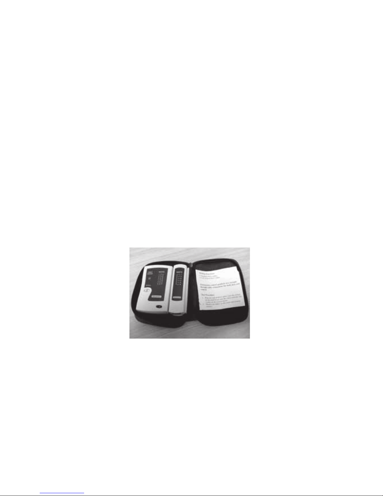
NOTE: It is important to test all cables before installation.
Testing all cables to be used before the start of the installation will save
considerable diagnostic time if the fully installed system is subsequently found
to have a problem. Cable testing is quick and easy with a Zonemaster Cable
tester available from Polyaire.
Cable Tester (Item: 657089)
Pre - Installation
Page 10
10
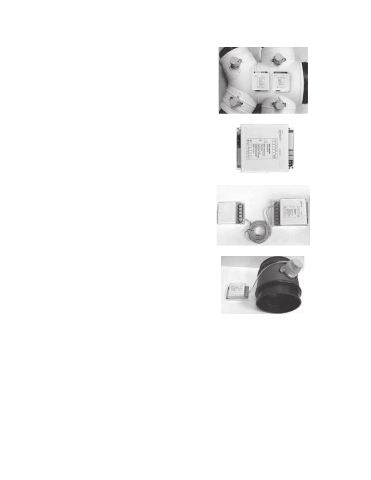
4.1 Mount the main and/or extension
modules (if using more than 8 zones) by
screwing the boxes to a roof frame or
Polyaire Diusion Fitting (PDF).
4.2 Remove the two side covers on the
main module. All LEDs and sockets for
zone dampers are exposed.
4.3 If the extension module is used,
connect main module to extension
module at ‘E/M’ port on both modules
with a left latched cable.
4.4 Use pre-tested cable to connect ‘Z1’
port on the main module to the
motorized damper of the 1st zone.
4.5 Repeat step 6.4 to connect other
zone dampers to their relevant zone
ports on the main and extension
modules.
Components Installation
4. Components Installation
Page 11
11
Components Installation
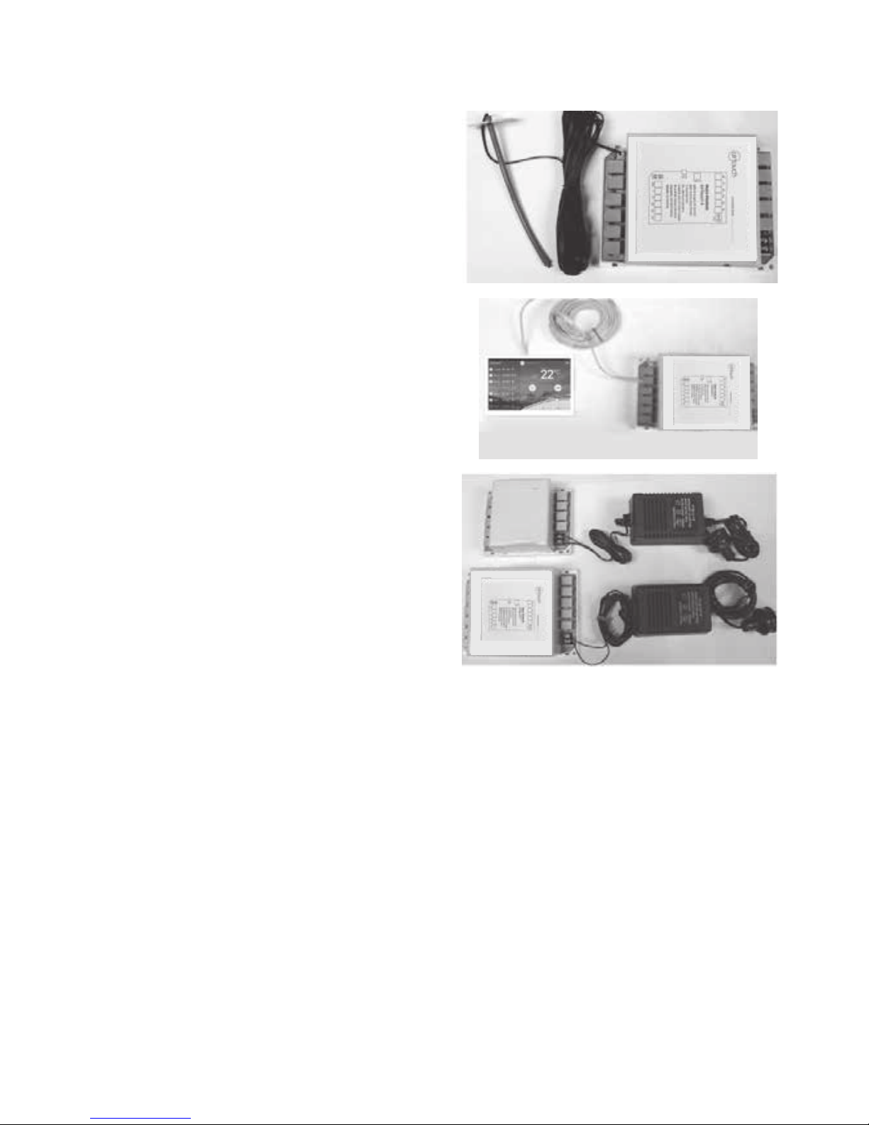
4.6 Mount the supply air sensor in the
supply air duct between the fan coil and
the rst damper and push the plug of
supply air temperature sensor into the
socket on the main module.
4.7 Connect the console to the ‘T’ port
on the main module. If two consoles
are used, connect one to T on the main
module and the other to the extension
module.
4.8 Connect the 24V AC transformer to
screw terminals on the main control
module. If extension module is used,
connect another 24 VAC transformer
to the screw terminals of the extension
module.
4.9 Connect the main module to the
AC unit using the required kit for the
respective AC unit (cables and interface
board). Follow the wiring diagram for
the respective unit provided on Page
33-62 of this manual.
Page 12
12
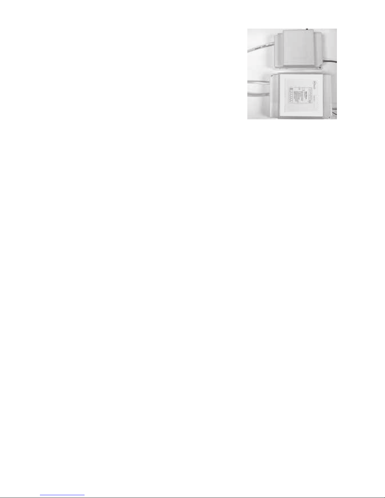
4.10 Replace the side covers back on the main
control and extension module once nished setting
and commissioning.
4.11 Remove the cover of the ITC from the base. Install the base with screws in
proper positions where there is no direct sun, no draft and about 1.5m above
ground. Set the correct group number and identication number (Sub ID) for
each sensor. And activate the battery to start the wireless sensor. Then align the
cover with the base and click the cover to position to complete the sensor
installation.
4.12 Fit the Console to wall
The plastic casing of the console consists of two halves. The front cover
contains the PCB board along with the LCD/console. The back cover
attaches to the wall as a mounting base. During the installation process the case
will have to be opened to mount the console on the wall. Follow the steps below
to carefully install the console to the wall:
a. Slide the back base to bottom side to clear the stops on the front cover
b. Remove the base from the front cover
c. Position the back base on the wall where the cable is (about 1.5m high from
the oor). Ensure it is away from any heat or cool source and mark the cable
hole and screw holes.
Note: The correct back cover direction is marked on its surface; follow that
mark when xing the back cover.
Component Installation
Continued on next page
Page 13

13
Component Installation
d. Cut the rectangular hole for the cable and x the back base to the wall by
using four screws on the marked positions.
e. Retrieve the console cable (from main control module) out of the cable hole and
plug it into the console.
f. Align the bottom edge of the back base with the bottom inside of the front cover
and the two side edges of the back base with the front cover.
Continued on next page
Page 14
14
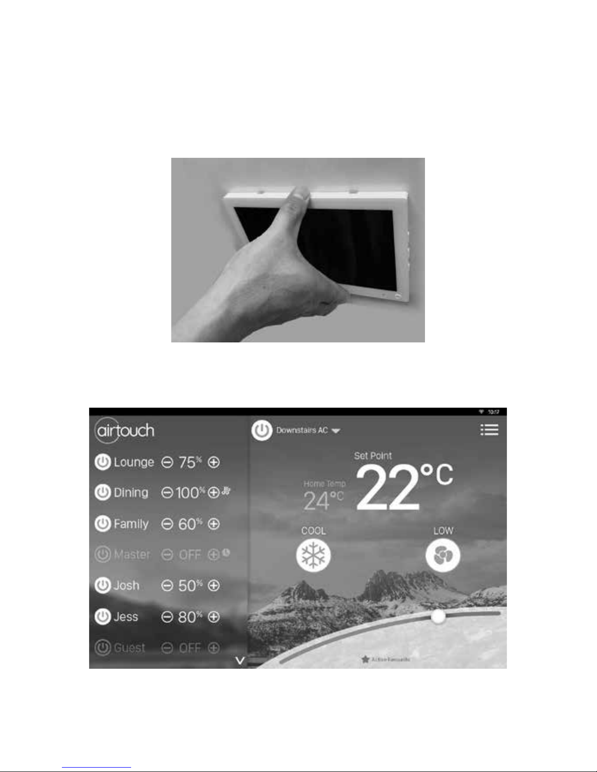
g. Gently push the front cover against the wall and make sure the back of front
cover is ash against the wall. And then push the front cover downwards with two
gures holding the top side of the front cover where there are two slots till the two
snap-ons click in.
Component Installation
Page 15
15
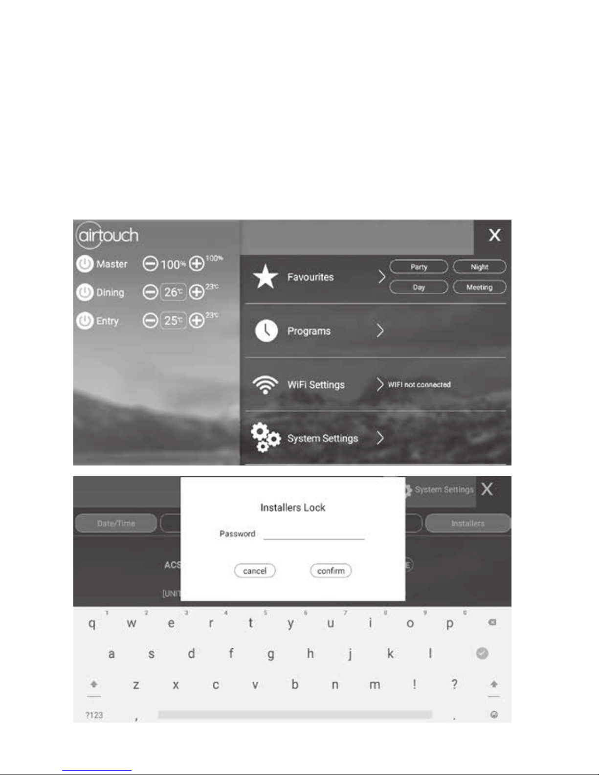
There are two sets of settings, the installer’s and user’s. In the installer’s settings,
the followings can be set: parameters, balancing, sensors, spill, grouping, service
and AC. These settings are protected by a password which has default value
Polyaire but can be changed. Touching Installer’s button in the Settings list will
bring up password input page. After inputting the correct password, installer’s
setting page will come up. In the user’s settings which are discussed in User’s
Manual, the followings can be set: owner name, date/time, group name, WiFi,
turbo group, temperature display, touch tone, child lock and temperature alert.
5. Recommended Commissioning Procedure
Recommended Commissioning Procedure
Page 16
16
5.1 Parameters
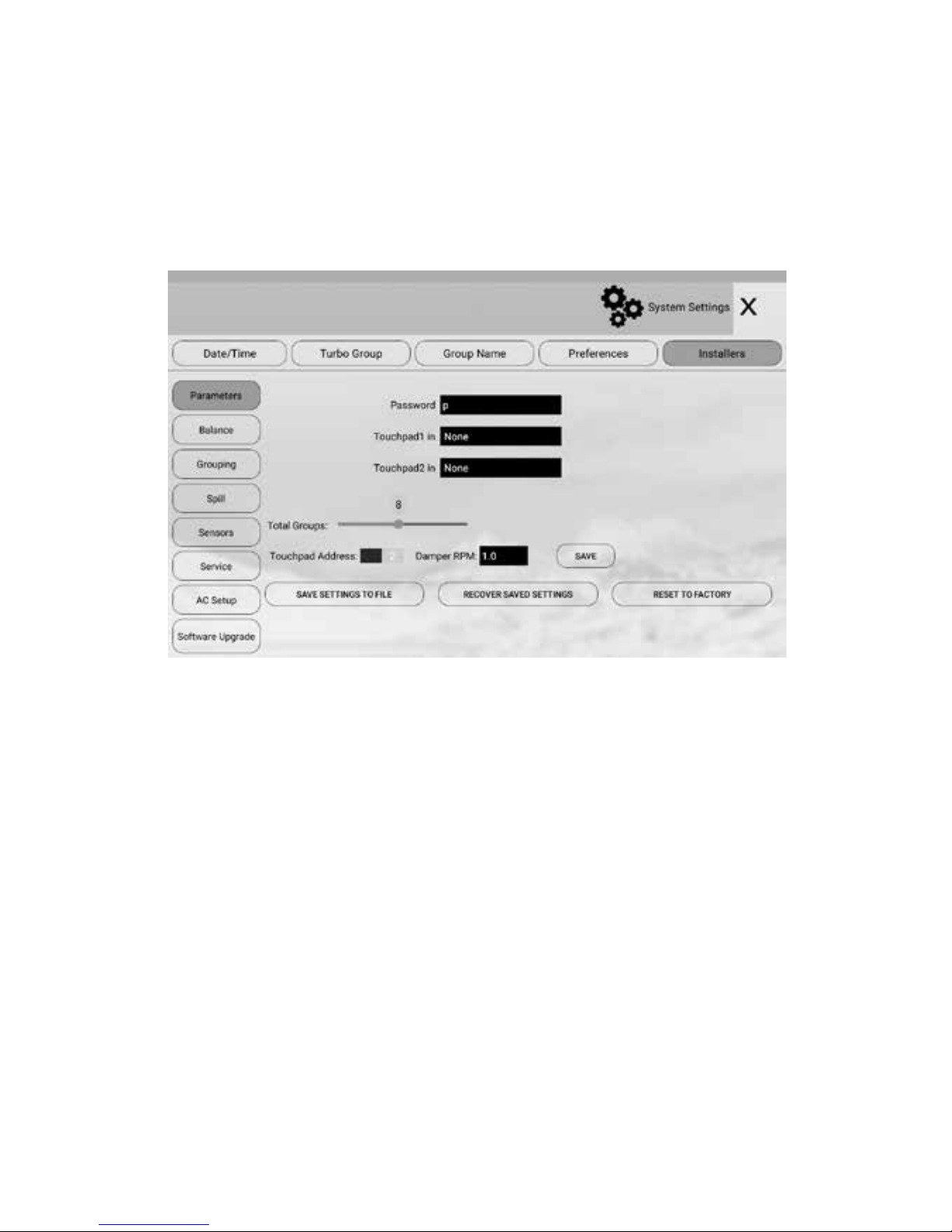
5.1.2 Total Groups in the System
For the purpose of group status display and spill zone calculation, the system
needs to know the total number of groups to be installed. The factory default
number is 8.
IMPORTANT: This number must be equal to the total group number used in the
system as planned in Pre-Installation process. If this is wrong, the system may
not work properly.
5.1.1 Console in Group or for AC control
The console sensor can be used for controlling temperature in a group or an
AC unit. In this case, it should be assigned to the AC unit or the group where the
console is installed.
5.1.3 Console Address
Up to two consoles can be installed in one AirTouch 4 system. Each console is set
as Master (1) in default. If two consoles are installed in the same system, one shall
be set to Master (1) and the other is set to Slave (2). The master console will
manage WiFi communications. It’s recommended to set the console in a position
closer to the home router as the master to have a better WiFi communication
between the home router and the AirTouch 4.
NOTE: Each console must have a unique address.
Two consoles with the same address will cause communication problems
between the main control module and the consoles.
NOTE: Touch Save button to save all changes.
Parameters
Page 17

17
5.1.4 Damper RPM Setting
AirTouch 4 can work with other dampers which are not made by Polyaire. But the
damper motors have to meet certain requirements:
Power supply: 24 VAC
Drive Open and Drive Close
Revolution per Minute (RPM): 0.1 to 2.5
5.1.5 Installer Settings Password
The password is used to prevent unauthorized changing of the installer settings.
To reset this password, touch the password edit eld in the ‘Parameter’ screen,
and then type in the new password and touch ‘Enter’ key to conrm the password
change.
5.1.6 Reset and Save current system settings
To record all system settings, press Save Settings to File button. After the settings
have been saved successfully, it will be stored on the console in the name of
AtchV4_Setting_Id.txt. Please transfer the settings le to a micro SD card or send
it to an email address for permanent storage in case the console is unaccessible.
Use File Manager on the console to access the le under
/storage/emulated/0/airtouch.
If the main module has been replaced, the system can be recovered from this le.
After the settings le is stored under the folder /storage/emulated/0/airtouch,
press the Recover Saved Settings button to recover.
After successful recovery, the system has to be powered o for at least 30
seconds and then powered back on to use the recovered settings.
If the system needs to be reset to factory default settings in some cases, press
Reset to Factory. All group names and settings will be back to original factory
settings.
Parameters contd. & Balancing
Page 18

18
5.2 Balancing
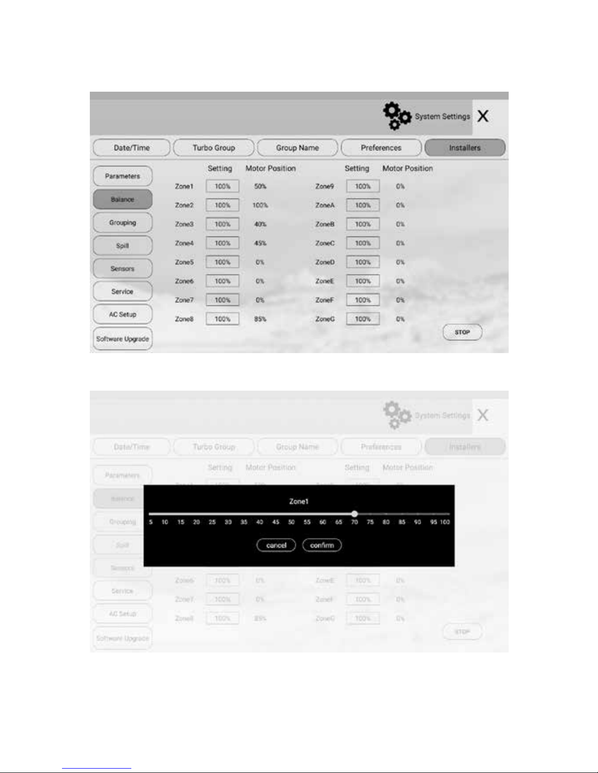
Electronic balancing feature of AirTouch 4 oers the exibility of balancing the
amount of airow to each zone electronically. Once the opening position of the
damper is set, the damper will only open to this position. The default setting for
each damper is 100% opening position and the adjustable range is between 0 and
100% with 5% increment. The balancing settings can be conducted on the touch
screen as below.
a) On ‘Installers’ screen, touch Balance menu
b) Touching the percentage value for the zone to start the balancing process.
All zones will open to its balanced position. You can input proper value and
check the airow on the y till right value reaches.
c) Repeat the process for all zones which need balancing. Then touch the Stop
button to stop the balancing process.
NOTE:
• The %OPEN value on the Zoning screen can be operated by the user for
additional air ow adjustment to the groups. The overall opening % of the
zone is calculated as %OPEN x Balance %.
Page 19
19
Page 20
20
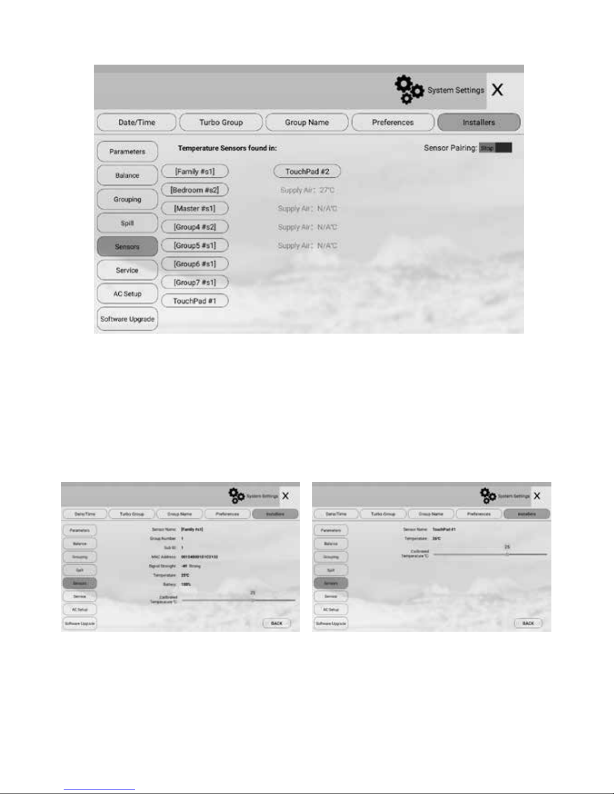
5.3 Sensors
Temperature sensors are used for measuring group temperature and control
group temperature and On/O if required. There are wireless temperatures
sensors and wired temperature sensors (on console). Each wireless sensor has
dipswitches to assign it to a particular group where it is installed and to be used
for temperature control of the group.
Balancing contd. & Sensors
Wireless Sensor Console Sensor
Page 21

21
5.3.1 Assign a sensor to a group
The console sensor can be assigned to a group where it’s installed in Parameter
settings. For a wireless sensor, open the wireless sensor cover and set the dial of
the group dipswitch (with 16 digits) pointing to the group number required.
Position 0 is for group 16. If there are more than one wireless sensor for the same
group, set the group dipswitch to the same position but dierent sensor ID by
switching the Sub ID dipswitch. If the group dial switch or sub ID switch has been
changed after pairing it’s necessary to re-pair the sensor. Otherwise the change
will not be eective.
5.3.2 Pair main module and wireless sensors (ITCs)
After assigning wireless sensors to relevant groups, it’s time to pair the sensors.
The AirTouch 4 main module and wireless sensors have to be paired to enable
communications. When AirTouch 4 is rst powered up, start the pairing process
on the Sensors page in the Installer’s Settings by switching the Pair button to Start,
then push and hold the button on each of the ITCs to be used in the system to
pair. All ITCs will come up and the groups with ITCs will show set points after being
paired. Then switch the Pair button to Stop to nish the pairing process.
5.3.3 Calibrate a Sensor
If the temperature reading from the sensor is not accurate, it can be calibrated by
changing the value in the calibration box on the sensor details page. Press Save
button to save the correct value.
Sensors contd.
Page 22
22
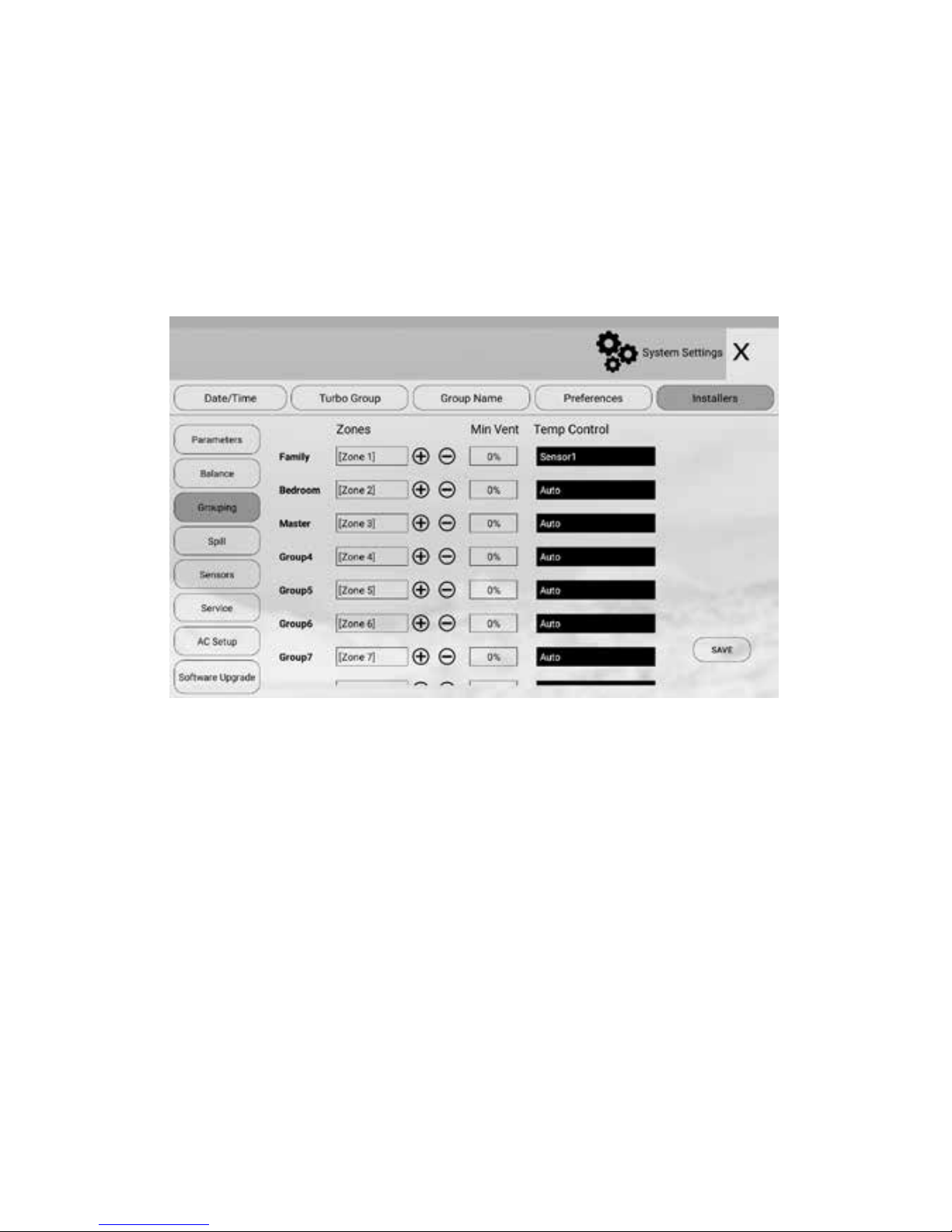
For ease of control operation, multiple zones can be grouped together.
The grouped zones are treated as one group with its own name and turned on
or o together. Individual balanced damper position is not aected by grouping,
which means zone balancing can be conducted before or after grouping.
Grouping can be carried out as follows:
a) In ‘Installers’ screen, touch Grouping to enter ‘Grouping’ screen.
5.4 Grouping Zones
b) Touch the edit eld of the group
c) and then touch + or - button to add or minus zones to the group
d) Repeat steps b) and c) to dene all groups
e) Press Save button to save the setting.
Grouping Zones
Page 23
23
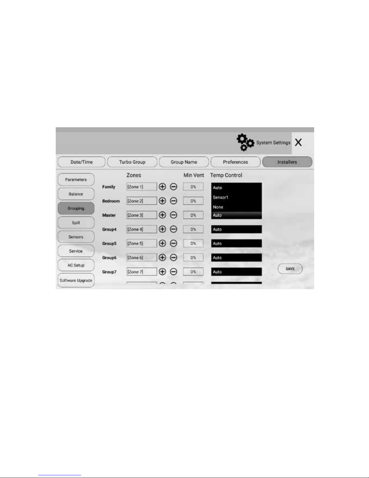
5.5 Choosing Group Temperature Control
If more than one sensor is assigned to the same group, options of using dierent
sensor combinations are available in Grouping section. Touch the eld after TC to
choose a wireless or console sensors as control temperature for the group. If there
is no sensor in the group, there will be no list for the group. If there is more than
one sensor, there will be a list for selection. The chosen sensor or average of all
sensors in the group will be used for controlling the temperature in the group.
Press Save button to save the setting.
If the group has only one temperature sensor, its temperature will be the control
temperature for the group. In default, the Auto is selected. The system will
automatically choose none, one sensor or average of two sensors when there is
no sensor, one sensor or two sensors,
When the group control temperature is activated, all zone dampers in the same
group will act against this temperature.
NOTE: The maximum number of zones in a group is four. The zones to be
grouped will be consecutive zones. The factory default for grouping is that
each group has one zone.
Choosing Group Temperature
Page 24
24
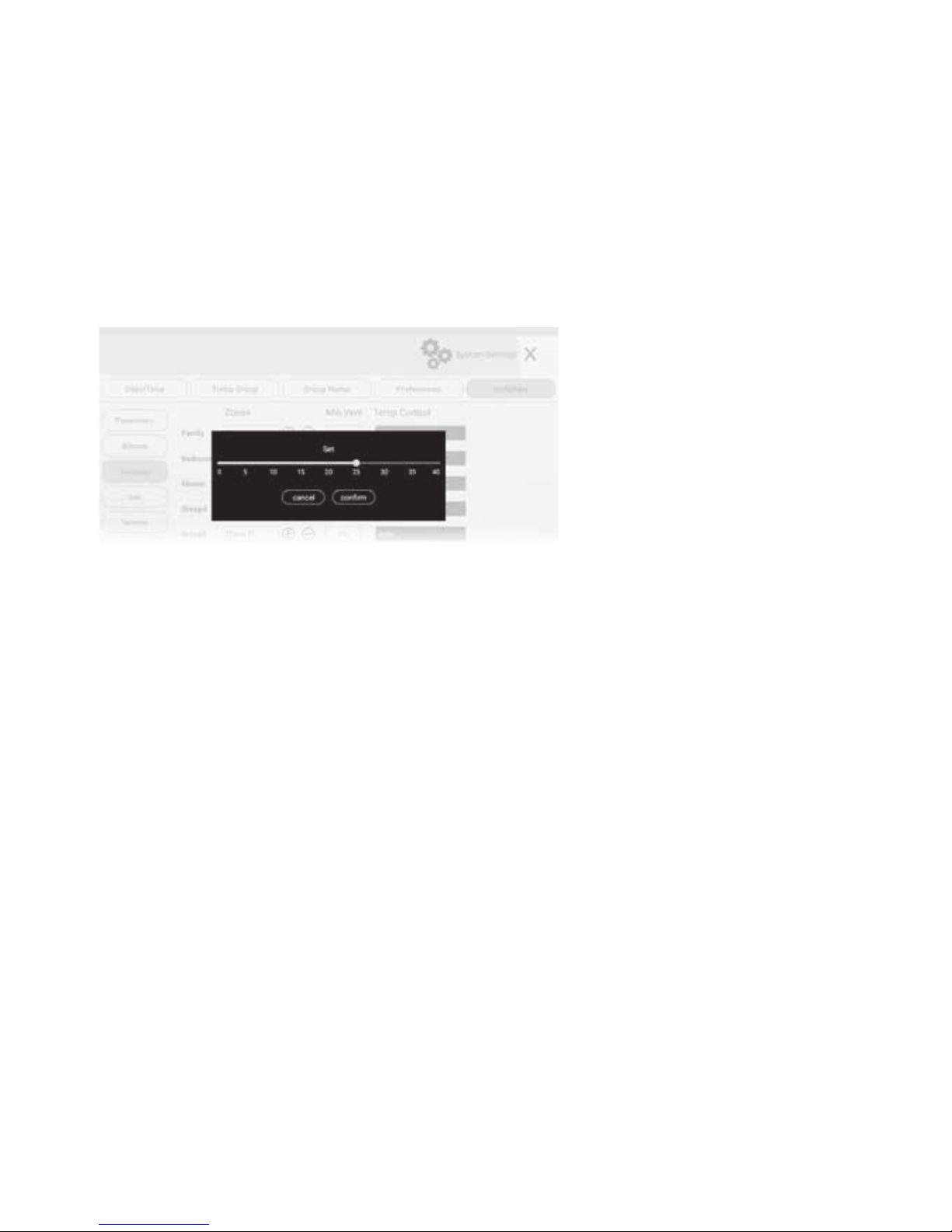
5.6 Setting Minimum Ventilation
Groups with ITCs can have minimum ventilation settings to meet relevant
requirements in light commercial applications. This is done in grouping settings.
Go to Grouping page, set the Min Vent for each group which has temperature
control. When the set point has reached, the damper of the group will not be fully
closed but have the set Min Vent opening to circulate the air. But if the group is
turned o, the damper will be fully closed. The maximum ventilation is 40%.
Press Save button to save the setting.
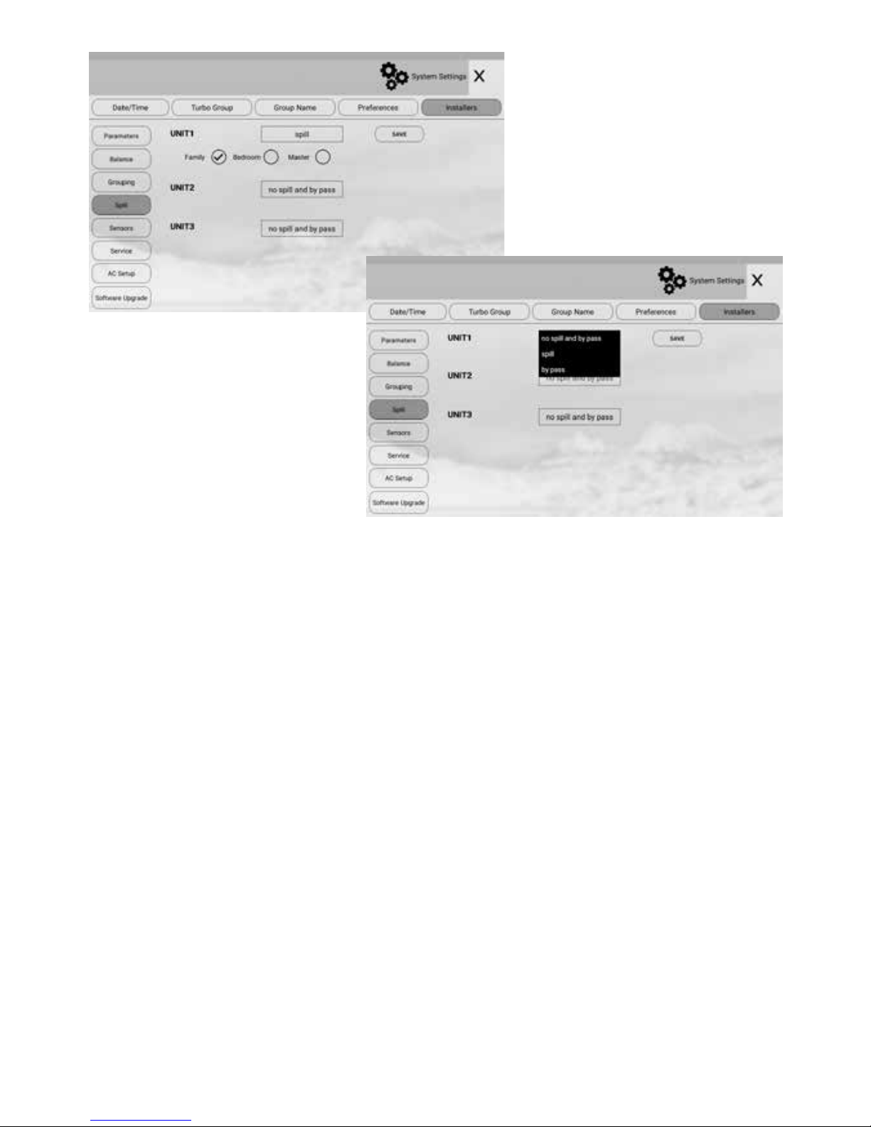
5.7 Spill or Bypass
Spill or bypass mode is a safety feature of the AirTouch 4 system to prevent
pressure from building up and causing duct damage. This usually occurs if
someone has turned o all groups while the A/C unit is pumping air into the
system leading to a pressure build-up (and potential of duct puncture, blow-os
or joints splitting).
It is designed to automatically open dampers if someone attempts to shut down
all dampers thus preventing pressure build up. Spill function opens the groups
chosen as spill groups in the system when all groups are being closed. Bypass
function opens the bypass damper which connects the supply duct to the return
duct directly when all groups being closed. When choosing groups for spill, it is
strongly recommended NOT to use bedrooms as spill groups. During sleep time if
the air conditioner is on and spill groups are forced to open, the spill groups will be
very cold or hot.
The system will maintain the number of groups chosen as spill groups open at any
time when AC is running. For instance, there will be at least two groups open if two
groups are chosen for spill. The rst group in the chosen spill group list will open
rst to spill. The maximum number of spill groups is half of the total groups.
Press Save button to save the setting.
Continued on next page.
Setting Minimum Ventilation & Spill or Bypass
Page 25
25
IMPORTANT: Choose at least one group as spill group unless there is a
permanent open zone used as spill zone. Otherwise, there will be no spill group
when all zones are closed and damage may be caused by high pressure
building up inside ducts if air conditioner is running. The Bypass and Spill cannot
be set at the same time.
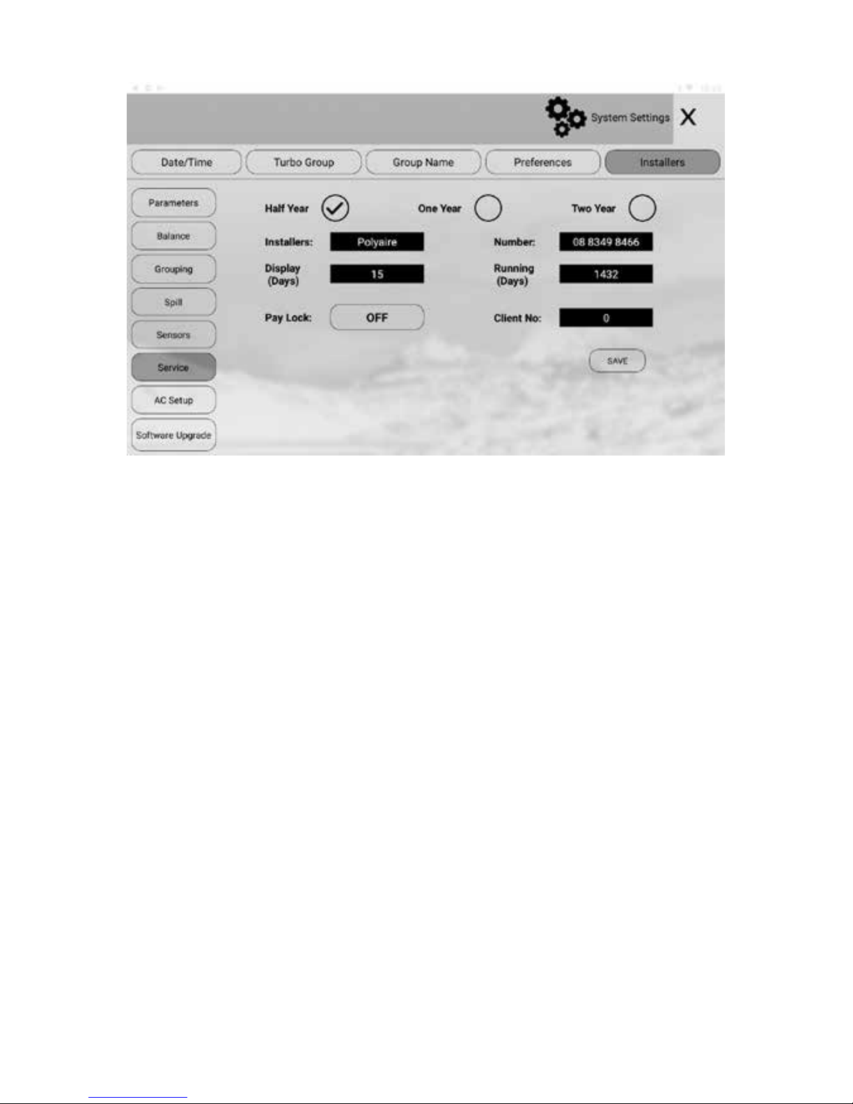
5.8 Enabling/Disabling Service Reminder
There is a built-in service reminder in the system for half year, one year and two
years to automatically display an alert notifying customers that the air
conditioning system is due for service. Installers can also use this feature to leave
their details such as their names and contact number.
The service reminder will display ‘HALF YEAR SERVICE DUE’, ‘ONE YEAR SERVICE
DUE’ or ‘TWO YEAR SERVICE DUE’ and installer’s name and contact number on
console for the set number of days if it has been enabled for half year (182 days),
one year (364) and two years (728 days) respectively since the air conditioning
system has been commissioned or serviced. The Running days in the ‘Service’
screen will automatically reset to 1 after 728 days or can be manually changed.
The Service Reminder is disabled by default but can be enabled as follows:
Continued on next page
Enabling/Disabling Service Reminder
Page 26
26
a) In the ‘Installer’ settings screen, touch Service to enter the ‘Service’ screen.
b) Touch the service reminder option buttons to enable or disable the relevant
reminders.
c) Touch the edit eld to change to the desired setting. The installer name
and number can be entered by using a keyboard. Make sure to touch Enter
to conrm the input. Touch the number and change Display and Running
days via keyboard input.
d) Touch Save button to save.
Maximum length of the name is 10 characters and the phone number is 12 digits.
Reminder information will be displayed on the screen when the service is due for
the length of display days (5 days in the example). Touch the “x” button on the top
right corner of the message box will clear the alert but the message box will come
back when the screen wakes up from sleep next time.
To not show the message box before the set display days, tick the Don’t Show
Again box before closing the message box.
Enabling/Disabling Service Reminder contd.
Page 27
27
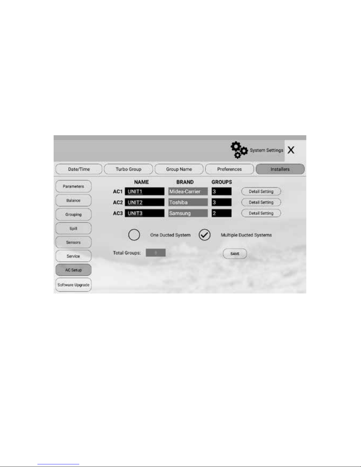
5.9 Setting up AC Control
If relevant gateways are connected to the AirTouch 4 main module, AirTouch 4
will automatically recognize the connected AC brands. The brands will be listed in
inactive color and cannot be changed. But the AC names are still editable.
In this case, AirTouch 4 will have full control of the ACs such as operation modes,
fan speeds and set point. The available gateways for the relevant ACs are Daikin,
Panasonic, Fujitsu, Mitsubishi Electric, Mitsubishi Heavy Industries, Toshiba, LG,
Hitachi, Samsung, Carrier, Rinnai, Actron (Slim), Midea, Braemar and Gree.
The wiring diagrams for full AC control are on section 6.
5.9.1 Name AC Units
The names of the AC can be edited as required. The default names are Unit and
Unit 2 for AC1 and AC2 respectively. Touch the name box will bring up keyboard
for editing. Touch Enter to conrm the new name. The maximum length of the AC
names is 8 characters. Touch Save button to save.
5.9.2 AC Detail Settings
The detail settings will have the exibility to use dierent sensors for AC control
and to congure fan speed options for various AC models and brands.
Setting up AC control
Page 28
28
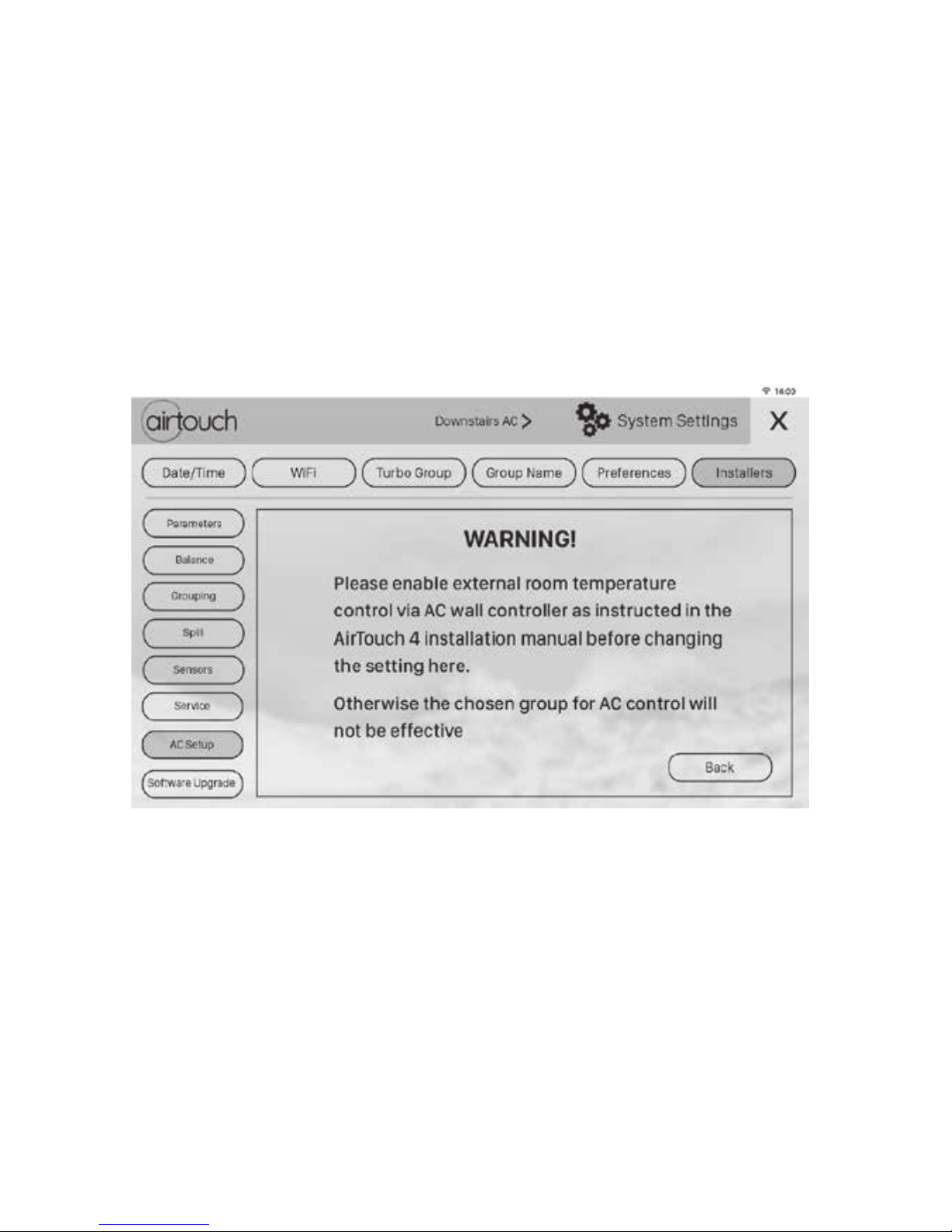
5.9.3
Choose AC Control Thermistor
In full AC control situation, the AC control temperature can be measured from
AC (its wall controller or return air sensor) or groups with temperature sensors.
The installer can select one which is better to represent the home temperature for
the AC unit. AC unit will use this value to take control.
Please check the commissioning notes for each model and ensure the AC unit is
enabled for remote temperature sensor control. Otherwise, the selected group
temperature sensor will not be used for AC control as expected even though the
console of AirTouch 4 will show the measured temperature from the group sensor.
Touch Save & Back to save the setting.
Setting up AC Control contd.
Page 29
29
5.9.4 Congure AC Fan Speed Options
AirTouch 4 can automatically recognise the total fan speed options from the
indoor unit in most cases. In rare cases, the installer may need to manually set the
fan speed options to match the actual fan speed options of the AC unit. First tick
the fan speed names and then change the fan speed matching number. As in the
image below, the Low fan speed number may be changed to 1, Medium to 2, High
to 3 and Powerful to 4.
Touch Save & Back to save.
5.9.5 Control Temperature Oset
The measured temperature from the selected control thermistor can be oset to
suit the situation. It’s up to the installer to choose the value.
Setting up AC Control contd.
Page 30
30
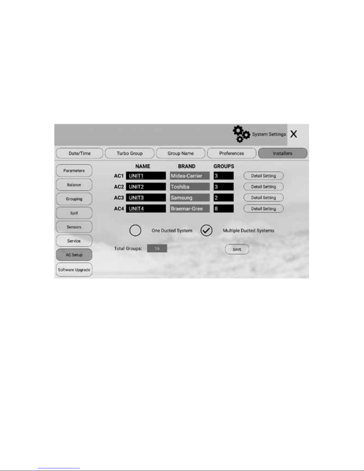
5.9.6 Multiple Ducted Systems
In multiple AC scenarios, the installation may be one ducted system or multiple
separate ducted systems. If multiple ACs supply conditioned air to the same
ducted system, this is classied as one ducted system and all ACs will have the
same spill and Turbo settings. If each AC has its independent supply and return air
ducts, it’s classied as Multiple Ducted System. In this case each AC will have its
own spill and Turbo settings. It’s up to the installer to choose one ducted system or
multiple ducted system.
5.9.7 Groups connected in each ducted system
In Multiple ducted systems, installers have to dene the group numbers for each
ducted system. The group number for each ducted system will help protect each
system from potential blown-out (by spilling) and set up separate Turbo group.
All zones from all ACs will be connected to the main module. If there are more
than 8 zones, the zones after 8 will be connected to the extension module in
sequential order. Touch Save button to save.
Setting up AC Control contd.
Page 31

31
The WiFi device is with the console which is an Android tablet. Connecting AirTouch
4 to the home router is the same as setting up WiFi for a normal Android tablet.
It’s in the Setting app on the tablet. If AirTouch 4 is running, minimize it and go to
Setting, nd WLAN and the available WiFi network will appear. Choose the correct
one and key in the password to connect. After successful connection, the Wi-Fi
logo will appear on the status bar. AirTouch 4 apps from Apple Store or Play Store
can be run from mobile devices now. The connection will stay permanent till the
setting changes on the home router such as SSID, password, security levels, lters
and others. The connection will automatically resume after power o and on cycle.
5.10 Setting up Wi-Fi Connection
5.11 Testing Damper On/O
a) Switch on the air conditioner.
b) Enter the home screen of AirTouch 4.
c) Touch the group buttons to turn groups on or o to check if the dampers are
correctly connected by feeling the air at the outlet.
d) The Turbo group can be tested by selecting the relevant chosen group as
Turbo mode in the 'Settings' and then press the group button until active
turbo mode is displayed on the screen for that particular group.
Setting up WiFi Connection & Testing Damper ON/OFF & Wiring Diagrams
Page 32
32
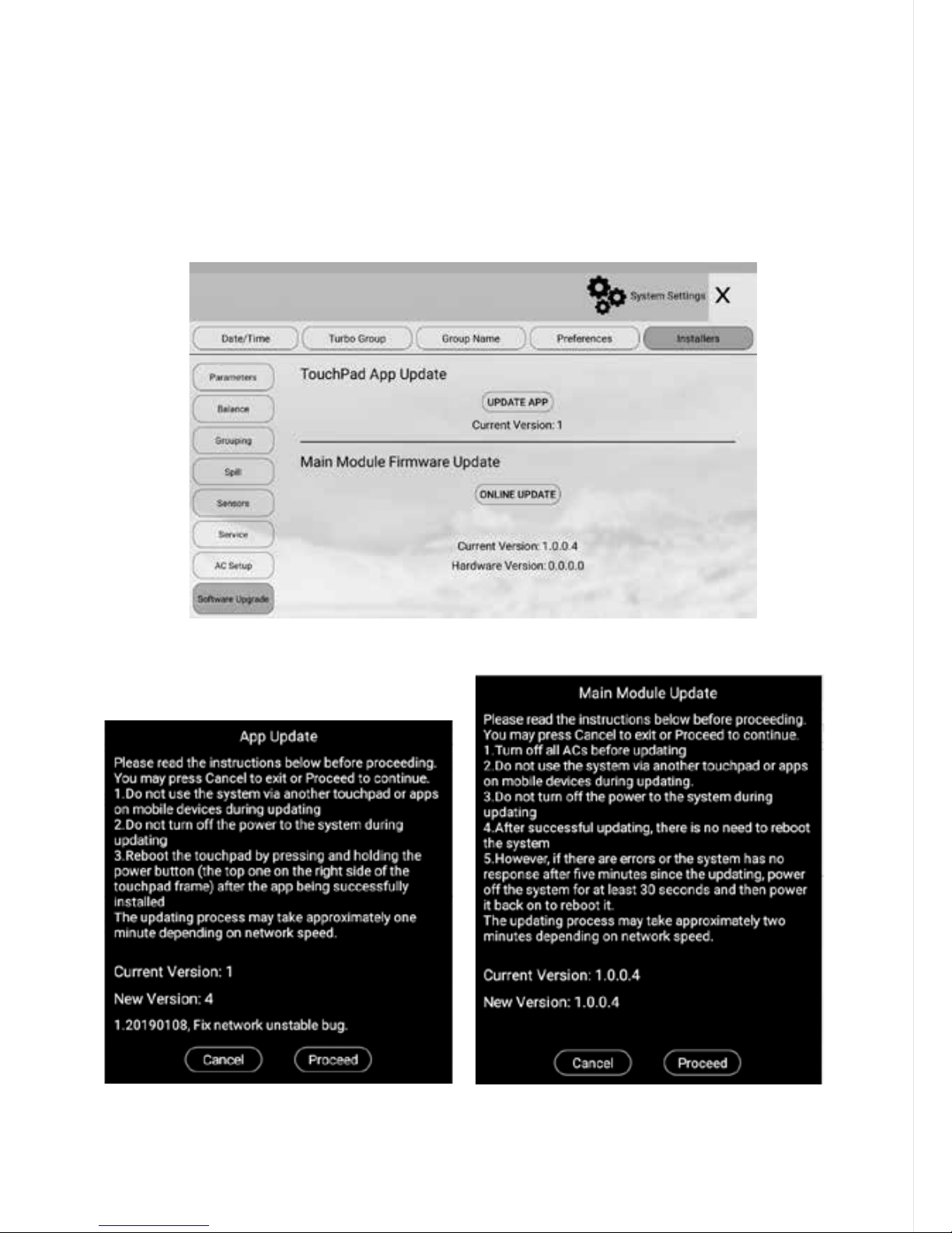
5.12 Software Update
AirTouch 4 console app and main module rmware can be updated online or
oine. For on line update, follow the instructions on the screen.
For oine update, please contact Polyaire.
In Installers’ Settings, select “Software Update” and follow the prompts.
The Touch Pad Console and Main Module are updated separately. Please run the
software update for both.
After completing the update, please check if the current version is the same as
the latest version by going into the update pages.
Page 33

6. Wiring Diagrams
• All AC Units must be initialised with Standard AC Wall Controller connected
to AC Indoor Unit to complete necessary eld settings and conrm the AC
runs normally
• Turn OFF power and disconnect Standard AC Wall Controller from AC Indoor
Unit if it’s not going to be used.
• Refer to relevant AC Gateway Drawings below to connect Gateway.
• Refer to Dip Switch settings (if applicable) on the Gateway Drawings below.
• After completing wiring and setting the dip switches, turn power ON. AC
Indoor, Gateway and AirTouch 4 can be powered up at the same time, but
power up AC Indoor and Gateway no later than the AirTouch 4.
33
Page 34

34
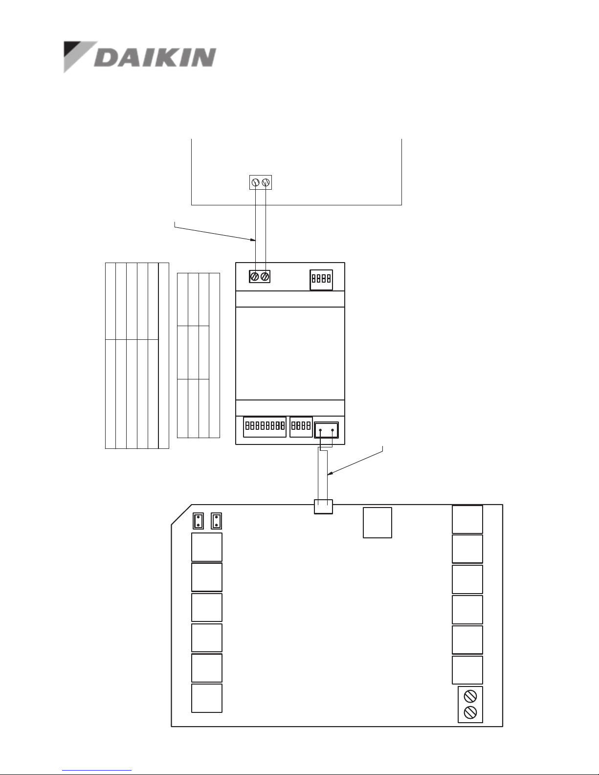
(
657212) Commissioning notes
1. Wire AirTouch 4, gateway and AC indoor as per diagram below and leave the
dipswitches on the gateway at their default position if the Daikin wall controller
is connected as Master. Make sure all wires are connected properly.
2. Initialise the AC Unit with Daikin AC Wall Controller connected. The Daikin wall
controller can be wired to P1 and P2 in parallel with the gateway.
3. If the Daikin wall controller is not going to be used after commissioning and
the return air sensor is used for AC temperature control. Turn o power and
disconnect the AC Wall Controller from AC Indoor Unit, and set position 1 of
S1 on the gateway to ON (1). Then restart the AC and gateway rst and then
power up AirTouch 4. Or power them up at the same time.
4. If AirTouch 4 sensors are used for AC temperature control:
• Settings on the Daikin AC wall controller: Set thermostat sensor to the remote
controller (Go to Field Setting, nd Mode 10 (20), code 2 and change its value to
01 or 03 depending on the wall controller model numbers, if there is any doubt,
please call Daikin to conrm ). Remove it after the setting if the Daikin wall
controller is not going to be used after commissioning. Otherwise, set Daikin AC
wall controller as sub controller.
• Settings on the gateway: set position 1 and 4 on the gateway to ON (1)
• Settings on the AirTouch 4 screen: Select the proper sensor or combination from
the Control Thermistor list for AC control in the Installer’s AC setting
• Restart the AC and gateway rst and then power up AirTouch 4. Or power them
up at the same time.
Wiring Diagrams contd.
Page 35
35
R
S
4
8
5
A
+
B
-
H
o
m
e
K
it
S/A2
E/M T Z1 Z2 Z3 Z4
Z8 Z7 Z6 Z5 B2 B1
L N
RS485
A+ B-
S3
S4
S1
S/A1-2: Supply Air Sensors
E/M: Extension Module
T: Touchscreen
Z1...Z8: Zone Dampers
L and N: 24V AC Power Supply
B1 and B2: Bypass Dampers
HomeKit: HomeKit Module
RS485: AC Gateway
AC Gateway
P1 P2
P1 P2
AirTouch 4
S/A1
657211 (RS485 Cable) from Polyaire
(Provided with the gateway)
Master/Slave Setting
S1 S4
Gateway As
0111 0000
Slave
1111 0000 Master
Two Core cable, stripped wires
field prepared
AC Indoor PCB
Gateway Address Setting
S3
Gateway Address
10000001 1
01000001211000001 3
00100001 4
657212
Note:
0-Off, 1-On
(
657212) Wiring Diagram
Wiring Diagrams contd.
Page 36

36
Firmware Version After 2.3
Important: It’s strongly recommended NOT to use the Panasonic wall controller
and the gateway at the same time. It may damage the indoor PCB in long term
and in extreme weather conditions.
1. Wire AirTouch 4, gateway and AC indoor as per diagram below and leave
the dipswitches on the gateway at their default position (gateway as Slave).
Make sure all wires are connected properly.
2. Initialise the AC Unit with Panasonic AC Wall Controller connected. The
Panasonic wall controller can be wired to R1 and R2 in parallel with the
gateway
3. Remove the Panasonic wall after commissioning and set the gateway as the
Master by switching position one of S1 to On (1)
4. If AirTouch 4 sensors are to be used for AC temperature control, go to AirTouch
4 AC setting and select proper sensor/combination.
(
657213) Commissioning notes
Wiring Diagrams contd.
Page 37
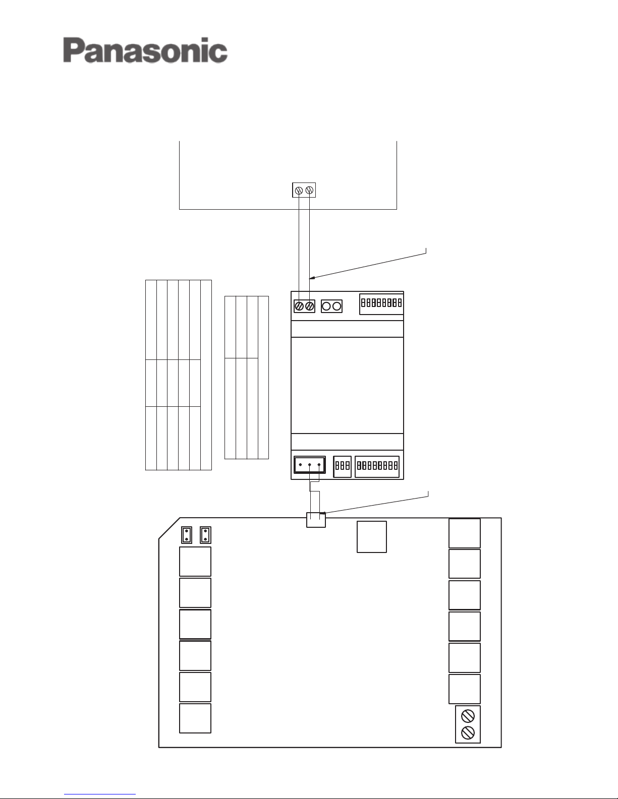
37
R
S
4
8
5
A
+
B
-
H
o
m
e
K
i
t
S/A2
E/M T Z1 Z2 Z3 Z4
Z8 Z7 Z6 Z5 B2 B1
L N
RS485
A+ B-
S3
S2
S1
S/A1-2: Supply Air Sensors
E/M: Extension Module
T: Touchscreen
Z1...Z8: Zone Dampers
L and N: 24V AC Power Supply
B1 and B2: Bypass Dampers
HomeKit: HomeKit Module
RS485: AC Gateway
AC Gateway
R1 R2
R1 R2
AirTouch 4
S/A1
657211 (RS485 Cable) from Polyaire
(Provided with the gateway)
Two Core cable, stripped wires
field prepared
AC Indoor PCB
Gateway Address Setting
S2 S3
Gateway As
10000000 000 1
01000000 000 2
11000000 000 3
00100000 000 4
657213
Note:
1. 0-Off, 1-On
2. This applies to firmware version after V2.3
Master Slave Selection
S1
Gateway As
01000010 Slave
11000010
Master
(
657213) Wiring Diagram
Firmware Version After 2.3
Wiring Diagrams contd.
Page 38

38
Firmware Version Before 2.3
Important: It’s strongly recommended NOT to use the Panasonic wall controller
and the gateway at the same time. It may damage the indoor PCB in long term
and in extreme weather conditions.
1. Wire AirTouch 4, gateway and AC indoor as per diagram below and leave the
dipswitches on the gateway at their default position. Make sure all wires are
connected properly.
2. Initialise the AC Unit with Panasonic AC Wall Controller connected. The
Panasonic wall controller can be wired to R1 and R2 in parallel with the
gateway
3. Remove the Panasonic wall controller after commissioning
4. If AirTouch 4 sensors are to be used for AC temperature control, go to AirTouch
4 AC setting and select proper sensor/combination.
(
657213) Commissioning notes
Wiring Diagrams contd.
Page 39
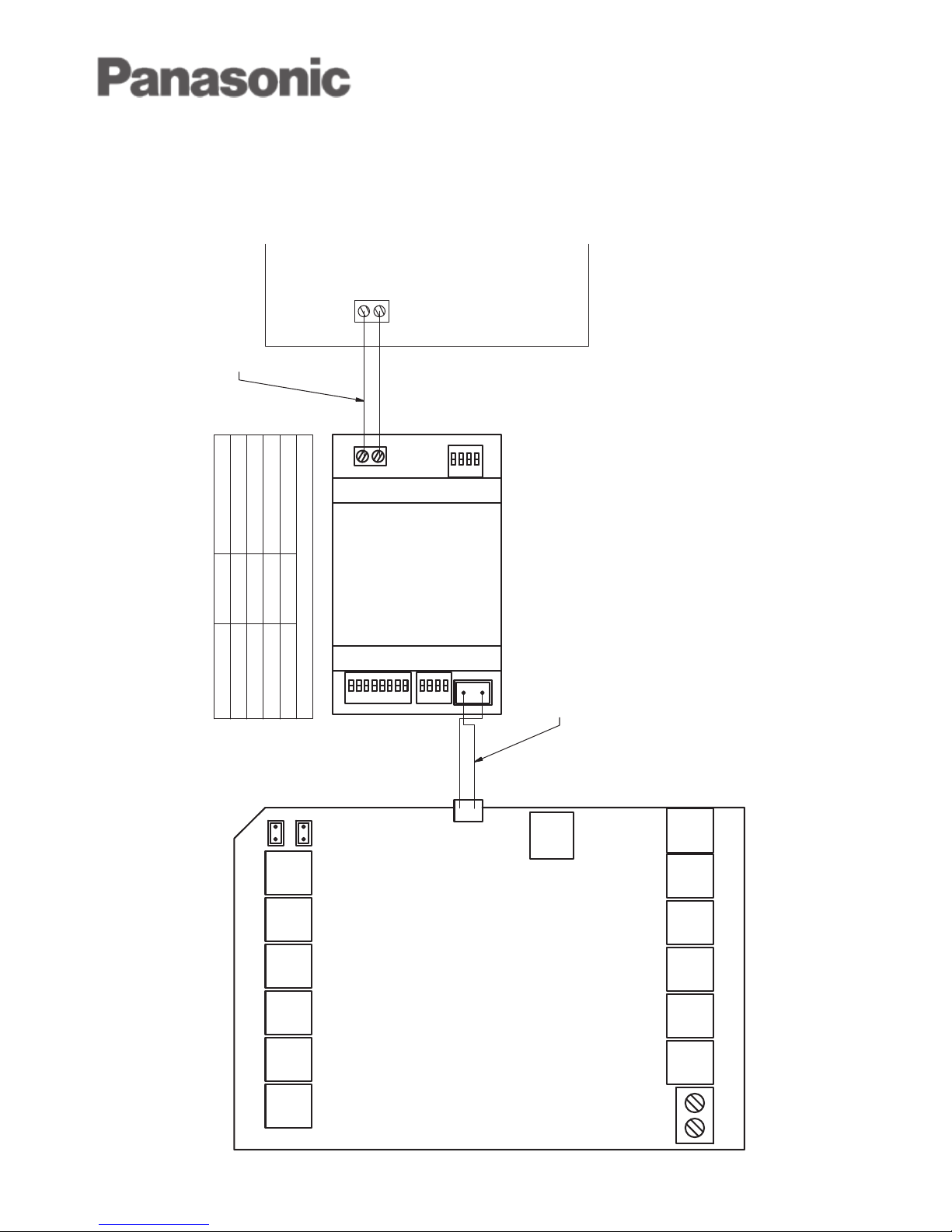
39
R
S
4
8
5
A
+
B
-
H
o
m
e
K
it
S/A2
E/M T Z1 Z2 Z3 Z4
Z8 Z7 Z6 Z5 B2 B1
L N
RS485
A+ B-
S3
S4
S1
S/A1-2: Supply Air Sensors
E/M: Extension Module
T: Touchscreen
Z1...Z8: Zone Dampers
L and N: 24V AC Power Supply
B1 and B2: Bypass Dampers
HomeKit: HomeKit Module
RS485: AC Gateway
AC Gateway
R1 R2
R1 R2
AirTouch 4
S/A1
657211 (RS485 Cable) from Polyaire
(Provided with the gateway)
Two Core cable, stripped wires
field prepared
AC Indoor PCB
Gateway Address Setting
S3 S4
Gateway As
10000001 0000 1
01000001 0000 2
11000001 0000 3
00100001 0000 4
657213
Note:
0-Off, 1-On
(
657213) Wiring Diagram
Firmware Version Before 2.3
Wiring Diagrams contd.
Page 40

40
1. Wire AirTouch 4, gateway and AC indoor as per diagram below and leave the
dipswitches on the gateway at their default position. If the indoor unit is a VRF,
please set the correct indoor type as per the Indoor Type Setting table in the
wiring diagram. Make sure all wires are connected properly.
2. Initialise the AC Unit with Toshiba AC Wall Controller connected. The Toshiba
wall controller can be wired to A and B in parallel with the gateway
3. Remove the Toshiba wall controller if it is not to be used after commissioning.
Otherwise, Toshiba’s wall Controller should be always set as Follower
4. If AirTouch 4 sensors are used for AC temperature control, go to AirTouch 4
AC Setup in Installer’s Settings and chose the proper temperature sensor
for AC control.
(
657218) Commissioning notes
Wiring Diagrams contd.
Page 41
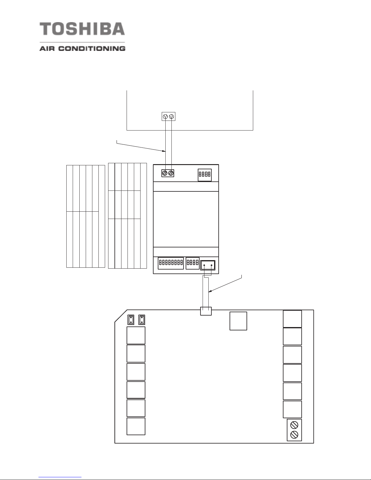
41
R
S
4
8
5
A
+
B
-
H
o
m
e
K
it
S/A2
E/M T Z1 Z2 Z3 Z4
Z8 Z7 Z6 Z5 B2 B1
L N
RS485
A+ B-
S3
S4
S1
S/A1-2: Supply Air Sensors
E/M: Extension Module
T: Touchscreen
Z1...Z8: Zone Dampers
L and N: 24V AC Power Supply
B1 and B2: Bypass Dampers
HomeKit: HomeKit Module
RS485: AC Gateway
AC Gateway
A B
A B
AirTouch 4
S/A1
657211 (RS485 Cable) from Polyaire
(Provided with the gateway)
Indoor Type Settings
S1 S4
Indoor Type
00xx 0000
Not Defined
10xx 0000 VRF-SMMSi
01xx 0000 RAV
11xx 0000
VRF-SMMS/SHRM
Two Core cable, stripped wires
field prepared
AC Indoor PCB
Gateway Address Setting
S3
Gateway Address
10000001 1
01000001211000001 3
00100001 4
657218
Note:
0-Off, 1-On, x-On or Off
(
657218) Wiring Diagram
Wiring Diagrams contd.
Page 42

42
1. Wire AirTouch 4, gateway and AC indoor as per diagram below and leave the
dipswitches on the gateway at their default position. Make sure all wires are
connected properly.
2. Initialise the AC Unit with Fujitsu AC Wall Controller connected. The Fujitsu wall
controller can be wired to B, W and R in parallel with the gateway
3. If Fujitsu wall controller is not to be used after commissioning and the return air
sensor is used for AC temperature control, set position 1 of S1 on the gateway
to ON (1) and restart the AC and AirTouch 4.
4. If AirTouch 4 sensors are used for AC temperature control:
Settings on the AC wall controller: Set thermostat sensor to the remote
controller (Go to Service->Function Setting, nd Function No 42, and set its
value to 01. Then go to Submenu and change “R. C. sensor control” from
O to On).
Remove the Fujitsu wall controller if it’s not to be used after commissioning.
Settings on the Gateway: Set position1 of S1 to ON (1)
Settings on the AirTouch 4 screen: Go to AC Setup and select the proper
temperature sensor for AC control Restart the AC and gateway rst and then
power up AirTouch 4 or power them up at the same time
(
657214) Commissioning notes
Wiring Diagrams contd.
Page 43
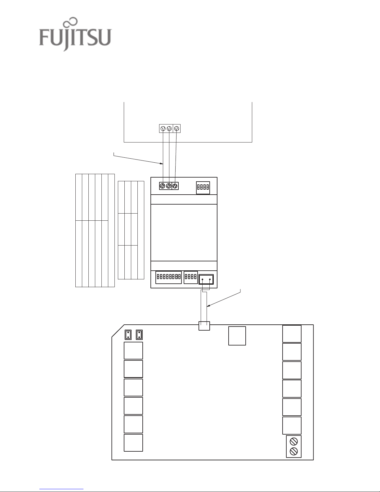
43
R
S
4
8
5
A
+
B
-
H
o
m
e
K
it
S/A2
E/M T Z1 Z2 Z3 Z4
Z8 Z7 Z6 Z5 B2 B1
L N
RS485
A+ B-
S3
S4
S1
S/A1-2: Supply Air Sensors
E/M: Extension Module
T: Touchscreen
Z1...Z8: Zone Dampers
L and N: 24V AC Power Supply
B1 and B2: Bypass Dampers
HomeKit: HomeKit Module
RS485: AC Gateway
AC Gateway
B W
R
(3 2 1)
AirTouch 4
S/A1
B W
R
(3 2 1)
657211 (RS485 Cable) from Polyaire
(Provided with the gateway)
Master/Slave Settings
S1 S4
Gateway As
0000 0000 Slave
1000 0000
Master
Three Core cable, stripped wires
field prepared
AC Indoor PCB
Gateway Address Setting
S3
Gateway Address
10000001 1
01000001 2
11000001 3
00100001 4
657214
Note:
0-Off, 1-On
(
657214) Wiring Diagram
Wiring Diagrams contd.
Page 44

44
1. Beware of the dierent dip switch settings for rmware before 2.0 and after
2.0 (including 2.0)
2. Wire AirTouch 4, gateway and AC indoor as per diagram below and leave the
dipswitches on the gateway at their default position. Make sure all wires are
connected properly.
3. Initialise the AC Unit with ME AC Wall Controller connected.
4. Remove the ME wall controller if it is not to be used after commissioning. Make
sure the AC control temperature is measured from the indoor unit return air.
5. Go to AC Setup and select the proper temperature sensor for AC control.
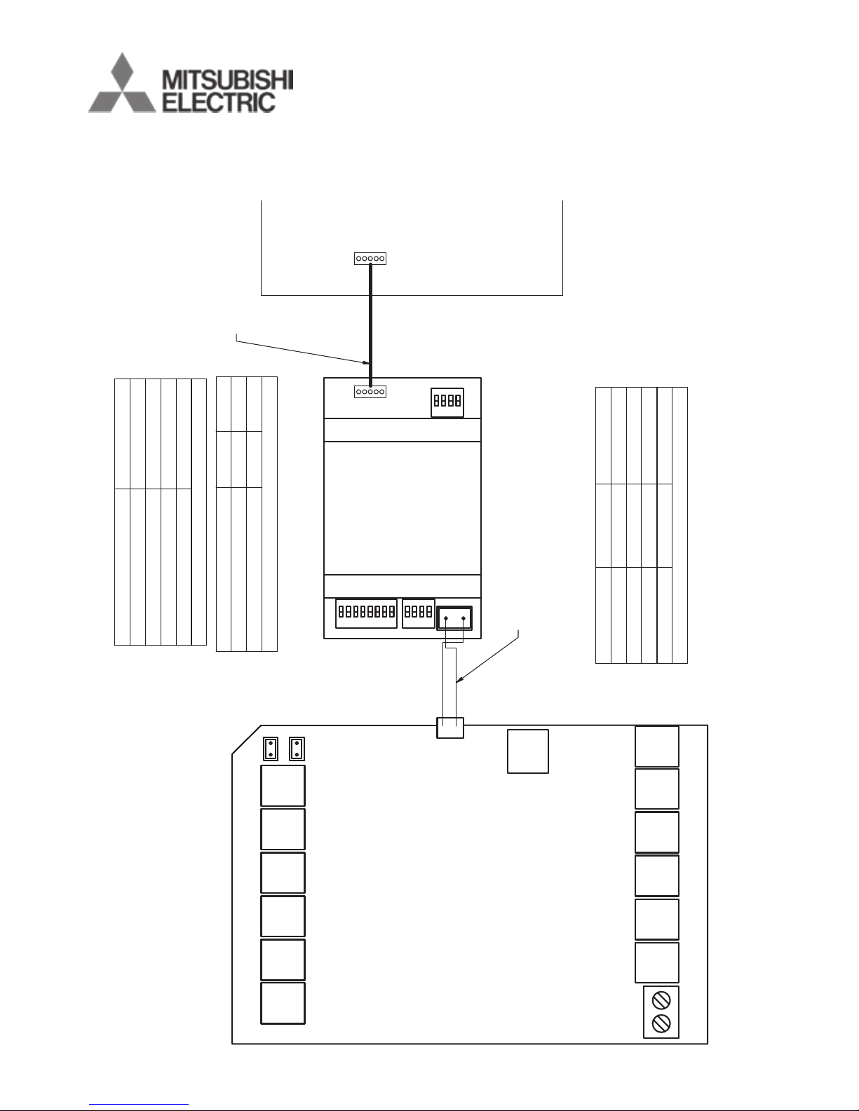
(
657215) Commissioning notes
Wiring Diagrams contd.
Page 45
45
R
S
4
8
5
A
+
B
-
H
o
m
e
K
it
S/A2
E/M T Z1 Z2 Z3 Z4
Z8 Z7 Z6 Z5 B2 B1
L N
RS485
A+ B-
S3
S4
S1
S/A1-2: Supply Air Sensors
E/M: Extension Module
T: Touchscreen
Z1...Z8: Zone Dampers
L and N: 24V AC Power Supply
B1 and B2: Bypass Dampers
HomeKit: HomeKit Module
RS485: AC Gateway
AC Gateway
CN92
CN105
AirTouch 4
S/A1
To AC
657211 (RS485 Cable) from Polyaire
(Provided with the gateway)
Fan Speed Settings
S1 S4
Total Fan Speed numbers
0000 0000 3 or 4
0001 0000 2
AC Indoor PCB
Gateway Address Setting
S3
Gateway Address
10000001 1
01000001211000001300100001 4
657215
Note:
0-Off, 1-On
Firmware before V2.0:
Gateway Address Setting
S3 S4
Gateway Addr
10000000 1000101000000 1000 2
11000000 1000 3
01000000 1000 4
Cable with plugs
(provided with the gateway)
Note:
1. 0-Off, 1-On
2. S1 is not used here
Firmware V2.0 and after:
(
657215) Wiring Diagram
Wiring Diagrams contd.
Page 46

46
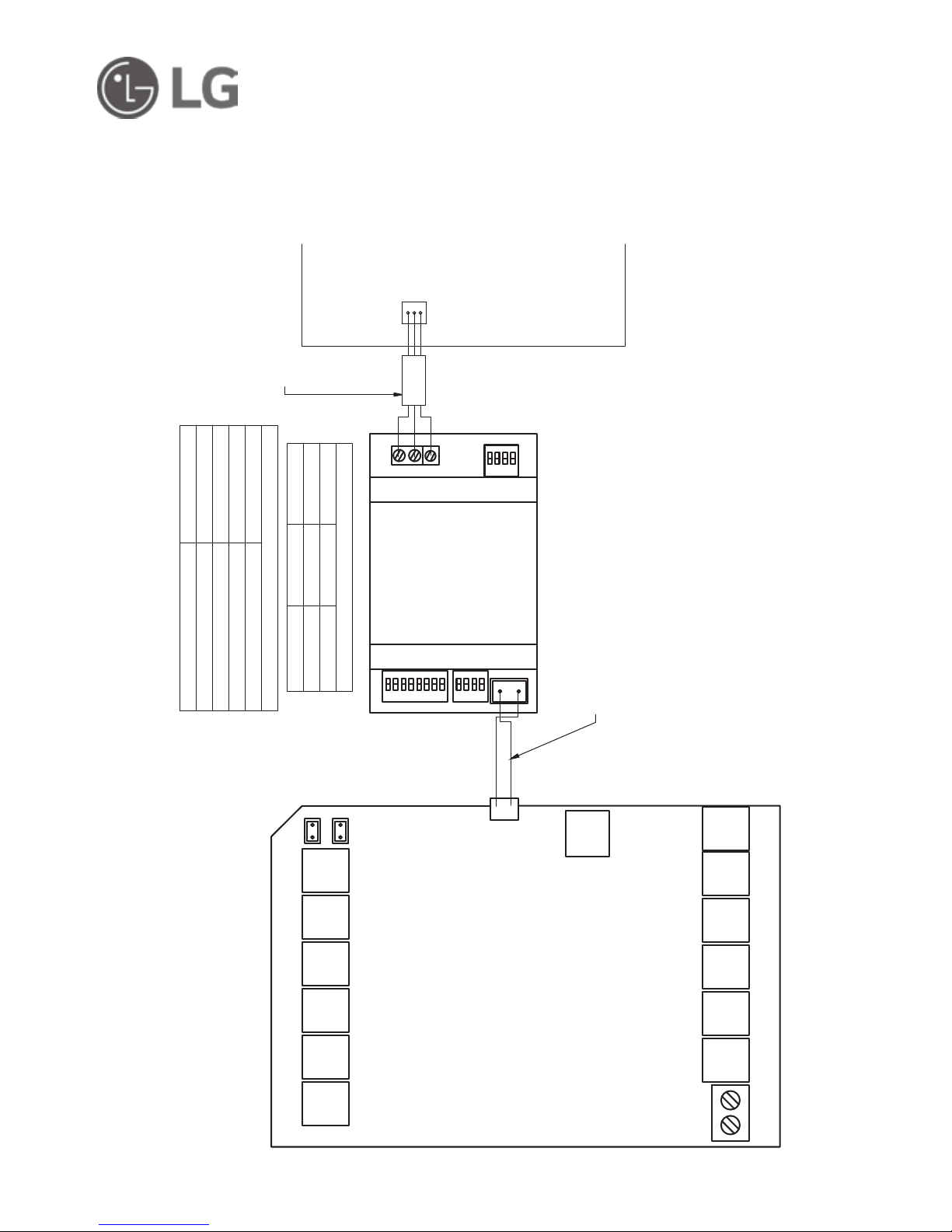
1. Wire AirTouch 4, gateway and AC indoor as per diagram below and leave the
dipswitches on the gateway at their default position. Make sure all wires are
connected properly.
2. Initialise the AC Unit with LG AC Wall Controller connected. The LG wall
controller can be wired to CN-REMO in parallel with the gateway.
3. If the LG wall controller is not going to be used after commissioning and the
return air sensor is used for AC temperature control: Turn o power and
disconnect the AC Wall Controller and set position 1 of S1 on the gateway to
ON (1). Then restart the AC and gateway rst and then power up AirTouch 4.
Or power them up at the same time.
4. If AirTouch 4 sensors are used for AC temperature control:
Settings on the LG AC wall controller: Set thermostat sensor in the remote
controller (Go to Function Setting (Zone->Setting->Sensor), change it to REMO.
Remove it after the setting if the LG wall controller is not going to be used after
commissioning.
Settings on the gateway: set position 1 of S1 on the gateway to ON (1)
Settings on the AirTouch 4 screen: Go to AC Setup and select the proper
temperature sensor for AC control.
Restart the AC and gateway rst and then power up AirTouch 4. Or power
them up at the same time.
(
657219) Commissioning notes
Wiring Diagrams contd.
Page 47
47
R
S
4
8
5
A
+
B
-
H
o
m
e
K
it
S/A2
E/M T Z1 Z2 Z3 Z4
Z8 Z7 Z6 Z5 B2 B1
L N
RS485
A+ B-
S3
S4
S1
S/A1-2: Supply Air Sensors
E/M: Extension Module
T: Touchscreen
Z1...Z8: Zone Dampers
L and N: 24V AC Power Supply
B1 and B2: Bypass Dampers
HomeKit: HomeKit Module
RS485: AC Gateway
AC Gateway
CN-REMO
AirTouch 4
S/A1
B Y R
657211 (RS485 Cable) from Polyaire
(Provided with the gateway)
Master/Slave Settings
S1 S4
Gateway As
0000 0000 Slave
1000 0000
Master
AC Indoor PCB
Gateway Address Setting
S3
Gateway Address
10000001 1
01000001 2
11000001 3
00100001 4
657219
Note:
0-Off, 1-On
Three stripped wires
to LG wall controller (not shown)
or Three stripped wires
with a plug to CN-REMO
(
657219) Wiring Diagram
Wiring Diagrams contd.
Page 48
48
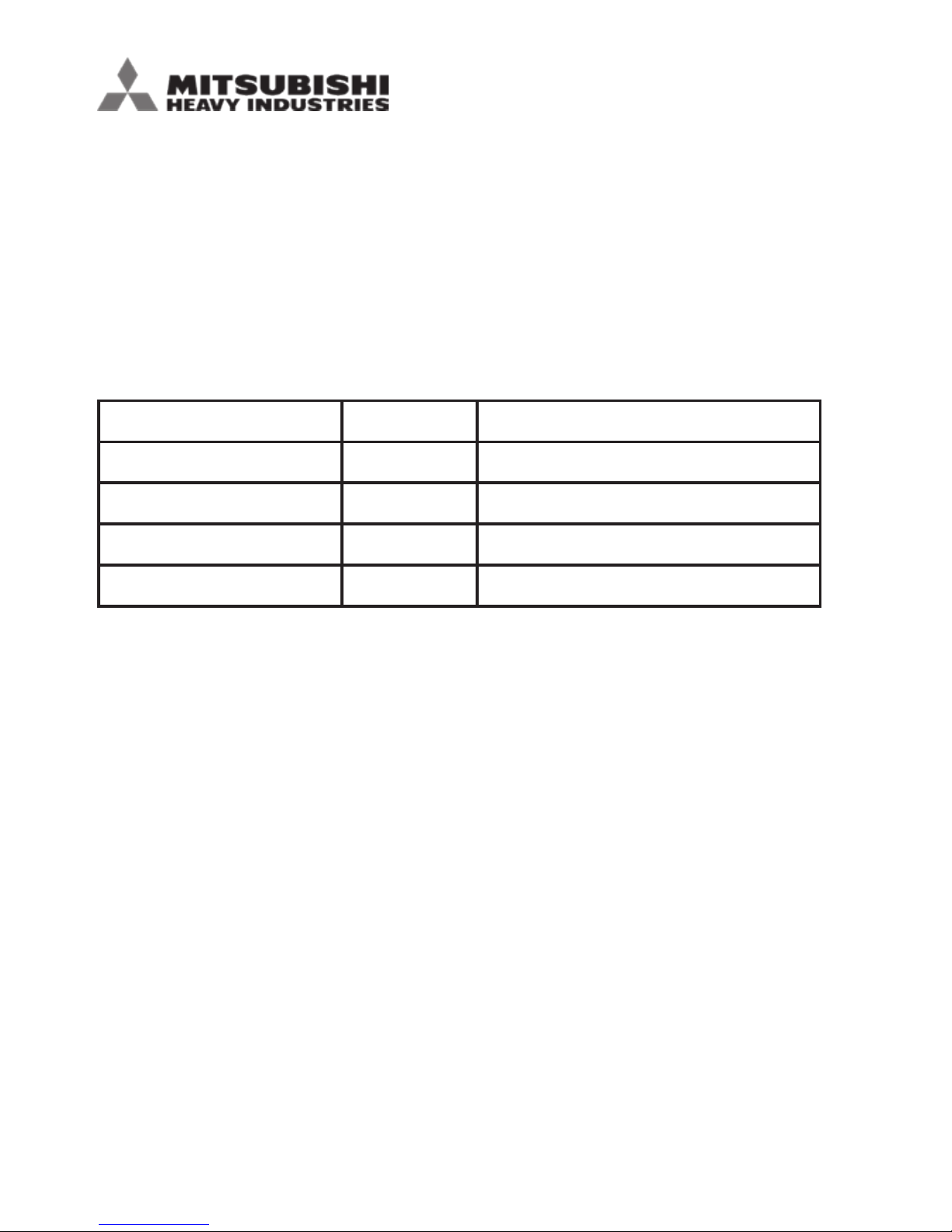
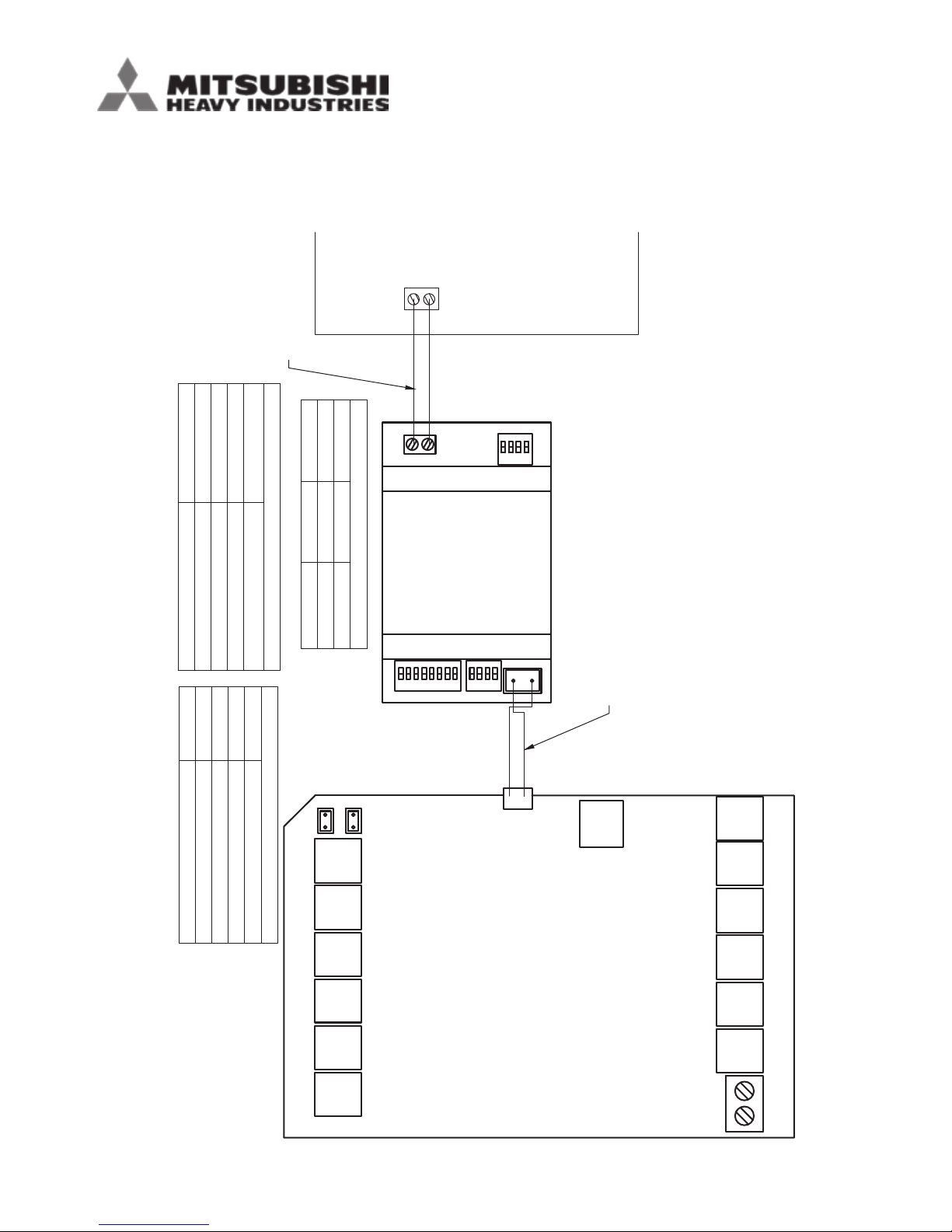
Commissioning Notes
1. Wire AirTouch 4, gateway and AC indoor as per diagram in the drawing and
leave the dipswitches on the gateway at their default position. Make sure all
wires are connected properly.
2. Set positions 2 and 3 of S1 on the gateway as per the table below according to
the indoor fan speeds:
Switches of S1 [1 2 3 4] Binary Value Description
x o o x x00x Indoor unit has 1 Fan Speeds
x o on x x01x Indoor unit has 2 Fan Speeds
x on o x x10x Indoor unit has 3 Fan Speeds
x on on x x11x Indoor unit has 4 Fan Speeds
3. Initialise the AC Unit with MHI AC Wall Controller connected. The MHI wall
controller can be wired to X and Y terminals in parallel with the gateway.
If the MHI wall controller is not going to be used after commissioning and the
return air sensor is used for AC temperature control:
Turn o power and disconnect the AC Wall Controller from AC Indoor Unit, and
set position 1 of S1 on the gateway to ON (1). Then restart the AC and gateway
rst and then power up AirTouch 4. Or power them up at the same time.
4. If AirTouch 4 sensors are used for AC temperature control:
Go to AirTouch 4 AC setting and choose the proper sensor from the Control
Thermistor list on AC setup.
MHI gateway rmware versions:
V0.13 and below will not work RC-EX3
V0.14 and higher works with RC-EX3
(
657216) Commissioning notes
Wiring Diagrams contd.
Page 49
49
R
S
4
8
5
A
+
B
-
H
o
m
e
K
it
S/A2
E/M T Z1 Z2 Z3 Z4
Z8 Z7 Z6 Z5 B2 B1
L N
RS485
A+ B-
S3
S4
S1
S/A1-2: Supply Air Sensors
E/M: Extension Module
T: Touchscreen
Z1...Z8: Zone Dampers
L and N: 24V AC Power Supply
B1 and B2: Bypass Dampers
HomeKit: HomeKit Module
RS485: AC Gateway
AC Gateway
X Y
X Y
AirTouch 4
S/A1
657211 (RS485 Cable) from Polyaire
(Provided with the gateway)
Master/Slave Settings
S1 S4
Gateway As
0xxx 0000 Slave
1xxx 0000
Master
Two Core cable, stripped wires
field prepared
AC Indoor PCB
Gateway Address Setting
S3
Gateway Address
10000001 1
01000001211000001 3
00100001 4
657216
Indoor Fan Speed Number
S1
Total Fan Speed Number
x00x 1
x01x2x10x 3
x11x
4
Note: 0-Off, 1-On, x-On or Off
(
657216) Wiring Diagram
Wiring Diagrams contd.
Page 50

50
(
657220) Commissioning Notes
1. Wire AirTouch 4, gateway and AC indoor as per diagram below and leave the
dipswitches on the gateway at their default position. Make sure all wires are
connected properly.
2. Initialise the AC Unit with Hitachi AC Wall Controller connected. The Hitachi wall
controller can be wired to A and B terminals in parallel with the gateway.
3. If the Hitachi wall controller is not going to be used after commissioning and
the return air sensor is used for AC temperature control: Turn OFF power and
disconnect the AC Wall Controller from AC Indoor Unit, and set position 1 of
S1 on the gateway to ON (1). Then restart the AC and gateway rst and then
power up AirTouch 4. Or power them up at the same time.
4. If AirTouch 4 sensors are used for AC temperature control:
• Settings on the Hitachi AC wall controller: Set thermostat sensor to the
remote controller (Go to Function Setting, nd Item C8, and change its value
to 01). Remove it after the setting if the Hitachi wall controller is not going to
be used after commissioning. Otherwise, set Hitachi AC wall controller as sub
controller (go to Function Setting, nd Item code F2, and set its value to 01)
• Settings on the gateway: set position 1 of S1 on the gateway to ON (1)
• Settings on the AirTouch 4 screen: Select the required temperature sensor
from the Control Thermistor list in AC setup in the Installer’s settings on
AirTouch 4
• Restart the AC and gateway rst and then power up AirTouch 4. Or power
them up at the same time.
• Note: Availability of AUTO mode in indoor unit depends on indoor unit
conguration (conguration is made from Hitachi wall controller). If it’s not
congured, changing to Auto will be accepted, but indoor unit will continue in
previous mode.
Wiring Diagrams contd.
Page 51
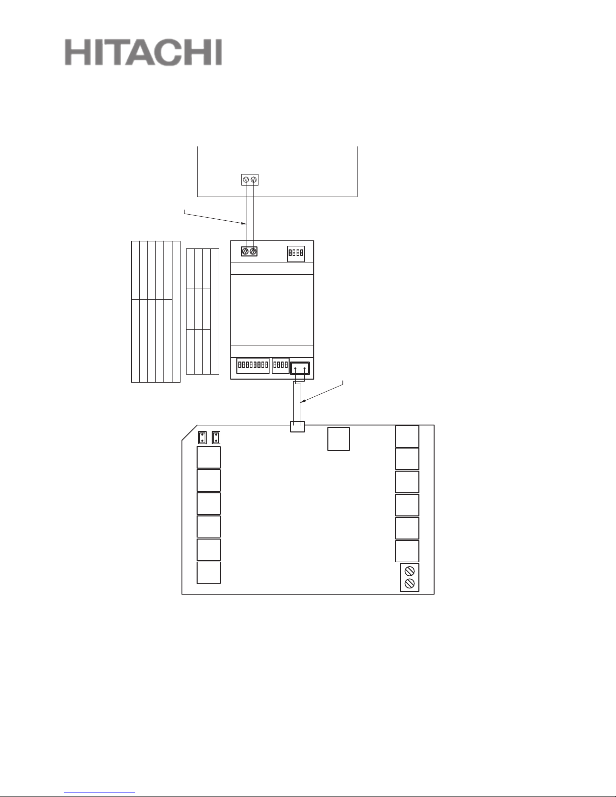
51
R
S
4
8
5
A
+
B
-
H
o
m
e
K
it
S/A2
E/M T Z1 Z2 Z3 Z4
Z8 Z7 Z6 Z5 B2 B1
L N
RS485
A+ B-
S3
S4
S1
S/A1-2: Supply Air Sensors
E/M: Extension Module
T: Touchscreen
Z1...Z8: Zone Dampers
L and N: 24V AC Power Supply
B1 and B2: Bypass Dampers
HomeKit: HomeKit Module
RS485: AC Gateway
AC Gateway
A B
AirTouch 4
S/A1
A B
657211 (RS485 Cable) from Polyaire
(Provided with the gateway)
Master/Slave Setting
S1 S4
Gateway As
0000 0000
Slave
1000 0000 Master
Two Core cable, stripped wires
field prepared
AC Indoor PCB
Gateway Address Setting
S3
Gateway Address
10000001 1
01000001211000001 3
00100001 4
657220
Note:
0-Off and 1-On
(
657220) Wiring Diagram
Wiring Diagrams contd.
Page 52

52
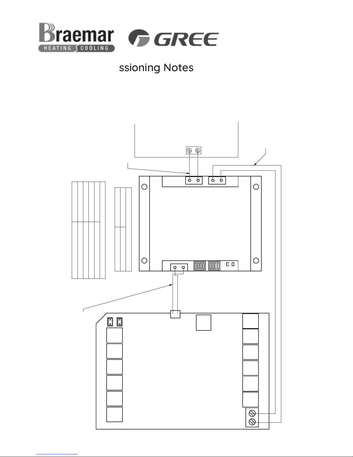
1. Wire AirTouch 4, gateway and AC indoor as per diagram below and leave the
dipswitches on the gateway at their default position. Make sure all wires are
connected properly.
2. Change mode 10 value to 01 via AC Wall Controller.
3. If AC Wall Controller is not going to be used after commissioning, change
mode 00 value to 01 via AC Wall Controller. Then remove the AC wall controller
(
657222) Commissioning Notes
Wiring Diagrams contd.
Page 53
53
R
S
4
8
5
A
+
B
-
H
o
m
e
K
it
S/A2
E/M T Z1 Z2 Z3 Z4
Z8 Z7 Z6 Z5 B2 B1
N L
RS485
A+ B-
S1
S2
S/A1-2: Supply Air Sensors
E/M: Extension Module
T: Touchscreen
Z1...Z8: Zone Dampers
L and N: 24V AC Power Supply
B1 and B2: Bypass Dampers
HomeKit: HomeKit Module
RS485: AC Gateway
AC Gateway
A B
AirTouch 4
S/A1
V1 V2
A B
CN1
COM-BMS2
657211 (RS485 Cable) from Polyaire
(Provided with the gateway)
Gateway ID Setting
S2 ID
0010
Braemar/Gree
Two stripped wires with two pin plug
(From Polyaire)
AC Indoor PCB
Gateway Address Setting
S1
Gateway Address
1000 1
010021100 3
0010 4
657222
Note:
0-Off, 1-On, x-On
Two stripped wires
(field prepared)
(
657222) Commissioning Notes
Wiring Diagrams contd.
Page 54

54
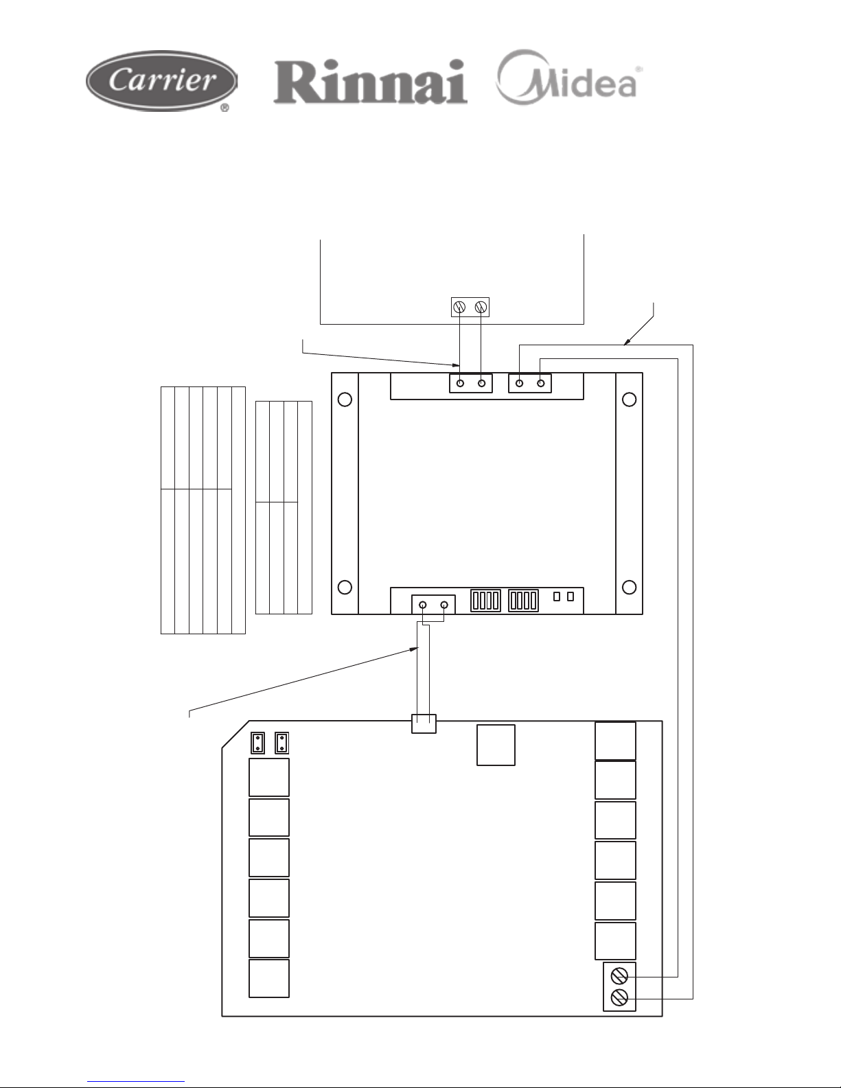
1. Wire AirTouch 4, gateway and AC indoor as per diagram below and leave the
dipswitches on the gateway at their default position. Make sure all wires are
connected properly.
2. Check the temperature compensation value setting (SW6 switch) on the indoor
PCB and make sure its value is set to EEPROM DEFAULT as per the instructions
on the wiring label at the back of the electrical box cover.
3. In default, AC will use its own return air sensor as control sensor. Installers can
set the AC control thermistor to an AirTouch 4 sensor by going to AC setup in
Installer’s Settings of AirTouch 4.
4. If the sensor on the AC wall controller is used for AC control (Follow Me feature
on the AC wall controller), please: Press the Follow Me button on the wall
controller to activate Follow Me. The displayed value for home temperature will
be the measured temperature where the AC wall controller installed.
(
657222) Commissioning Notes
Wiring Diagrams contd.
Page 55
55
R
S
4
8
5
A
+
B
-
H
o
m
e
K
it
S/A2
E/M T Z1 Z2 Z3 Z4
Z8 Z7 Z6 Z5 B2 B1
N L
RS485
A+ B-
S1
S2
S/A1-2: Supply Air Sensors
E/M: Extension Module
T: Touchscreen
Z1...Z8: Zone Dampers
L and N: 24V AC Power Supply
B1 and B2: Bypass Dampers
HomeKit: HomeKit Module
RS485: AC Gateway
AC Gateway
X Y
AirTouch 4
S/A1
V1 V2
X Y
657211 (RS485 Cable) from Polyaire
(Provided with the gateway)
Heat Mode Compensation Setting
S2 Value
0100 0.00
0111 4.00
Two stripped wires
(field prepared)
AC Indoor PCB
Gateway Address Setting
S1
Gateway Address
1000 1
010021100 3
0010 4
657222
Note:
0-Off, 1-On, x-On
Two stripped wires
(field prepared)
(
657222) Wiring Diagram
Wiring Diagrams contd.
Page 56

56
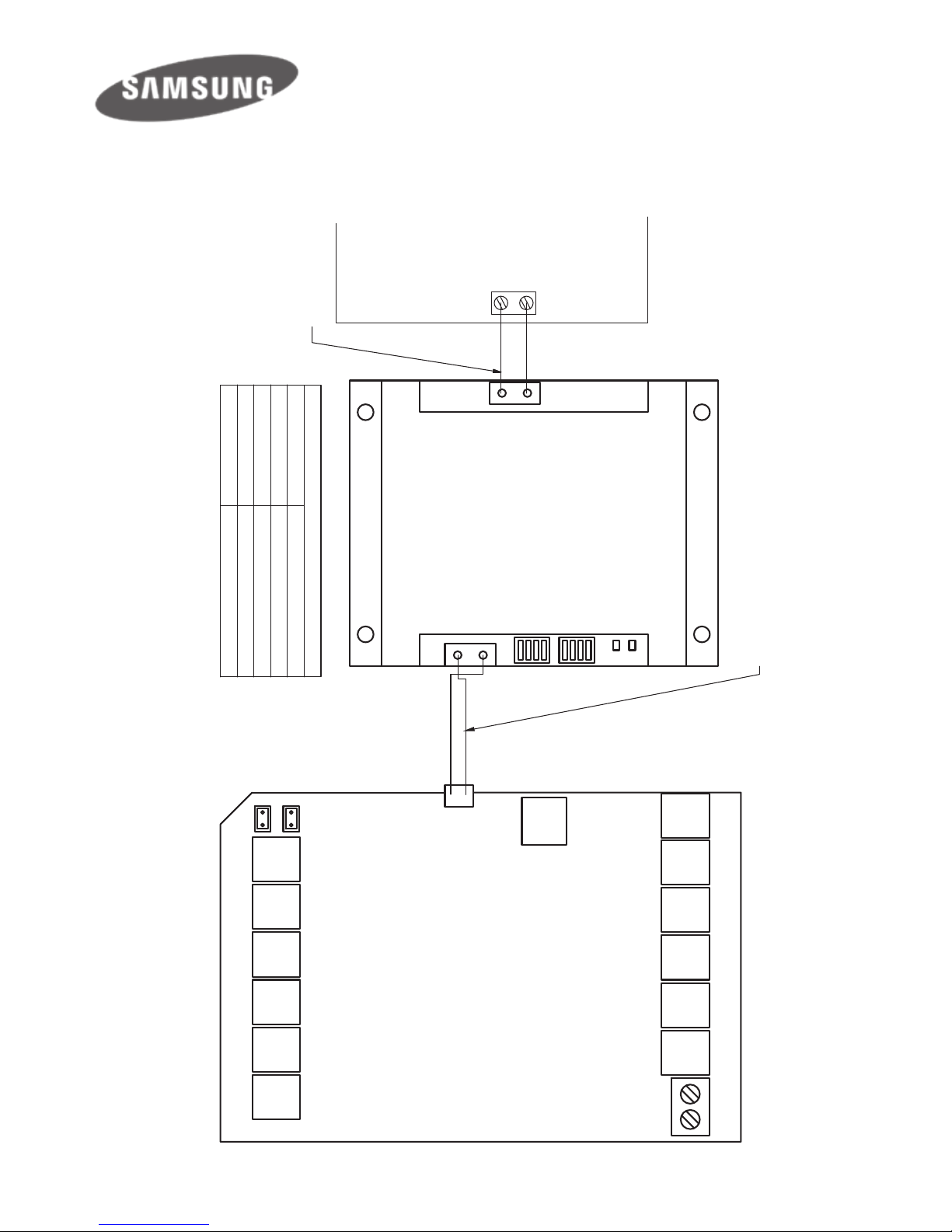
NOTE: This gateway will only work with units which have 16kW and above
capacity with MWR-WE10N wall controller (NASA protocol). Samsung wall
controller cannot be used at the same time.
1. Wire AirTouch, gateway and AC indoor as per diagram and leave the
dipswitches on the gateway at their default position. Make sure all wires are
connected properly.
2. Initialise the AC Unit. If AirTouch 4 sensors are used for AC temperature control:
• Settings on the AirTouch 4: choose from Control Thermistor list in the
Installer’s AC Setup.
• Settings from the Samsung wall controller: Go to Installation/Service Modes
by pressing and holding ESC and Set buttons together, nd Main Menu 1,
Submenu 2, and then set Data bit 1 to 1. After the setting, remove the
Samsung wall controller and use the gateway only.
• Restart the AC and gateway rst and then power up AirTouch. Or power
them up at the same time.
NASA (
657229) Commissioning Notes
Wiring Diagrams contd.
Page 57
57
R
S
4
8
5
A
+
B
-
H
o
m
e
K
it
S/A2
E/M T Z1 Z2 Z3 Z4
Z8 Z7 Z6 Z5 B2 B1
L N
RS485
A+ B-
S1
S2
S/A1-2: Supply Air Sensors
E/M: Extension Module
T: Touchscreen
Z1...Z8: Zone Dampers
L and N: 24V AC Power Supply
B1 and B2: Bypass Dampers
HomeKit: HomeKit Module
RS485: AC Gateway
AC Gateway
F3 F4
F3 F4
AirTouch 4
S/A1
657211 (RS485 Cable) from Polyaire
(Provided with the gateway)
Two stripped wires
(field prepared)
AC Indoor PCB
Gateway Address Setting
S1
Gateway Address
100010100 2
1100 3
0010 4
657229
Note:
1. 0-Off, 1-On, x-On
2. Samsung wall controller cannot be with the gateway at the same time
NASA (
657229) Wiring Diagram
Wiring Diagrams contd.
Page 58

58
NOTE: This gateway will only work with units which have 14kW and below
capacity with wall controller MWR-WE10 (Non-NASA protocol which is used in
the latest models with capacity of 14kW and below and some of the old indoor
models starting with “NS”).
Commissioning Notes
1. Wire AirTouch 4, gateway and AC indoor as per diagram and leave the
dipswitches on the gateway at their default position. Make sure all wires are
connected properly.
2. Initialise the AC Unit with Samsung AC Wall Controller connected.
3. If AirTouch 4 sensors are used for AC temperature control:
• Settings on the AirTouch screen: choose from Control Thermistor list in the
Installer’s AC Setup.
• Settings on the Samsung wall controller: Go to Installation/Service Modes
by pressing and holding ESC and Set buttons together, nd Main Menu 1,
Submenu 2, and then set Data bit 1 to 1.
• Restart the AC and gateway rst and then power up AirTouch. Or power
them up at the same time.
There are two versions of the gateway. They are interchangeable but please
follow the wiring as per below:
No-NASA (
657217
)
Commissioning Notes
Wiring Diagrams contd.
Page 59
59
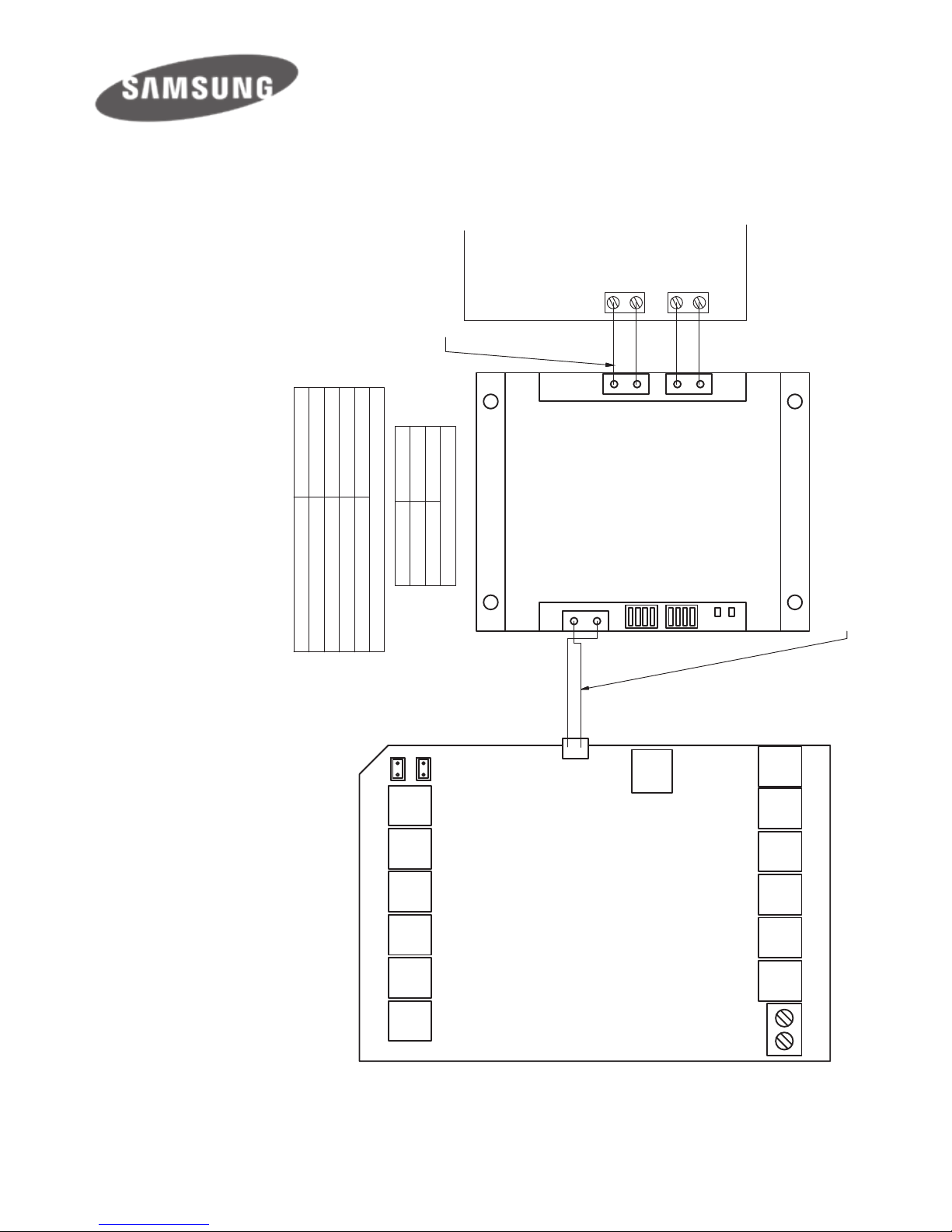
NOTE: If Samsung wall
controller is used with the
gateway, the Samsung wall
controller has to be set to
Master and the gateway has
to be set to Slave by switching
position 4 of S2 to 0 (O).
In this situation AirTouch 4
sensors cannot be used for
AC Temperature Control.
R
S
4
8
5
A
+
B
-
H
o
m
e
K
it
S/A2
E/M T Z1 Z2 Z3 Z4
Z8 Z7 Z6 Z5 B2 B1
L N
RS485
A+ B-
S1
S2
S/A1-2: Supply Air Sensors
E/M: Extension Module
T: Touchscreen
Z1...Z8: Zone Dampers
L and N: 24V AC Power Supply
B1 and B2: Bypass Dampers
HomeKit: HomeKit Module
RS485: AC Gateway
AC Gateway
F3 F4
F3 F4
AirTouch 4
S/A1
V1 V2
V1 V2
657211 (RS485 Cable) from Polyaire
(Provided with the gateway)
Master/Slave Setting
S2
Gateway As
0000
Slave
0001
Master
Four stripped wires
(field prepared)
AC Indoor PCB
Gateway Address Setting
S1
Gateway Address
1000 1
010021100 3
0010 4
657217
Note:
1. 0-Off, 1-On, x-On
2. This applies to gateways made in China
No-NASA (
657217
)
Wiring Diagram - New Version
Wiring Diagrams contd.
Page 60
60
R
S
4
8
5
A
+
B
-
H
o
m
e
K
it
S/A2
E/M T Z1 Z2 Z3 Z4
Z8 Z7 Z6 Z5 B2 B1
L N
RS485
A+ B-
S3
S4
S1
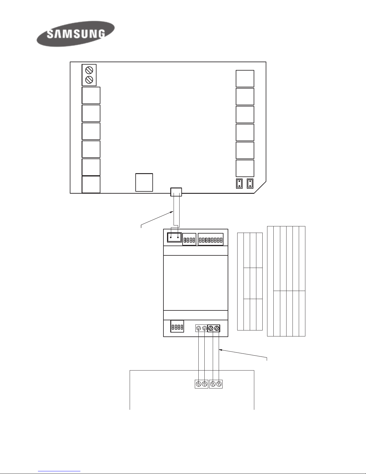
S/A1-2: Supply Air Sensors
E/M: Extension Module
T: Touchscreen
Z1...Z8: Zone Dampers
L and N: 24V AC Power Supply
B1 and B2: Bypass Dampers
HomeKit: HomeKit Module
RS485: AC Gateway
AC Gateway
F3 F4
F3 F4
AirTouch 4
S/A1
V1 V2
V1 V2
657211 (RS485 Cable) from Polyaire
(Provided with the gateway)
Master/Slave Setting
S1 S4
Gateway As
0000 0000
Slave
1000 0000 Master
Four Core cable, stripped wires
field prerpared
AC Indoor PCB
Gateway Address Setting
S3
Gateway Address
10000001 1
01000001211000001 3
00100001 4
657217
Note:
1. 0-Off, 1-On, x-On
2. This applies to gateways made in Spain
No-NASA (
657217
)
Wiring Diagram - Old Version
Wiring Diagrams contd.
Page 61

61
R
S
4
8
5
A
+
B
-
H
o
m
e
K
i
t
S/A2
E/M T Z1 Z2 Z3 Z4
Z8 Z7 Z6 Z5 B2 B1
N L
RS485
A+ B-
S1
S2
S/A1-2: Supply Air Sensors
E/M: Extension Module
T: Touchscreen
Z1...Z8: Zone Dampers
L and N: 24V AC Power Supply
B1 and B2: Bypass Dampers
HomeKit: HomeKit Module
RS485: AC Gateway
AC Gateway
CN24
AirTouch 4
S/A1
V1 V2
A B
YCJ-A002 Adaptor
12
COM1 G
CN1
B
A
SW1
BM1
ON
ON
1 2
657211 (RS485 Cable) from Polyaire
(Provided with the gateway)
Gateway ID Setting
S2
ID
0001 Haier
Three wire cable with plugs
(Provided with YCJ-A002)
(From Haier)
AC Indoor PCB
Gateway Address Setting
S1
Gateway Address
1000 1
0100 2
1100 3
0010 4
657222
Note: 0-Off, 1-On
Two stripped wires
(field prepared)
BM1
120 1
SW1
1 2 3 4 5 6 7 8
0 0 0 0 0 0 0 0
Note: 0-Off, 1-On
Wiring Diagrams contd.
1. Wire AirTouch, gateway, YCJ-A002 (supplied by Haier) and AC indoor as per
diagram. Make sure all wires are connected properly
2. Set the dipswitch settings on the YCJ-A002 and the gateway as shown on the
drawing as required
3. In default, AC will use its own return air sensor as control sensor. Installers can
set the AC control thermistor to an AirTouch 4 sensor by going to AC detail
setting in Installer’s Settings of AirTouch 4.
Page 62
62
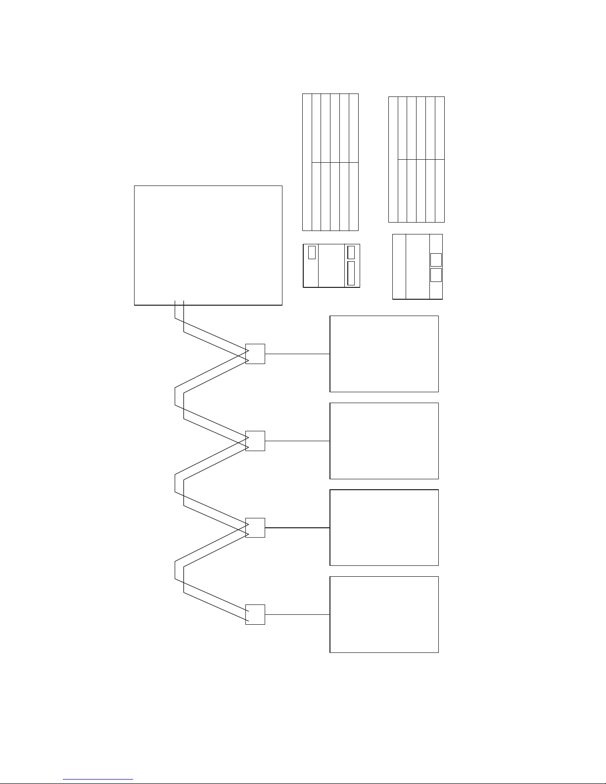
Multiple Gateways
If AirTouch 4 is to control more than one AC unit, gateways for multiple ACs can
be joined in serial as shown in the wiring above. Each gateway will be set with a
unique gateway address and as required for the AC connected.
AirTouch 4
AC4
AC1
AC2AC3
Gateway 1
Set by
Dipswitch
Gateway 2
Set by
Dipswitch
Gateway 3
Set by
Dipswitch
Gateway 4
Set by
Dipswitch
R
S
4
8
5
A
B
ABABB AAB
S3
S4
S1
Gateway
S1 S2
Gateway
Gateway with three sets of switches
S3 (12345678) Gateway Address
100xxxxx
Gateway 1
010xxxxx
Gateway 2
110xxxxx
Gateway 3
001xxxxx
Gateway 4
Gateway with two sets of switches
S1 (1234) Gateway Address
100x
Gateway 1
010x
Gateway 2
110x
Gateway 3
001x
Gateway 4
Wire the gateways to ACs as per gateway wiring diagrams
Wiring Diagrams contd.
Page 63

63
AirTouch 4 application can be downloaded from the following location.
The application is available for free of charge.
For Android Phones: Go to Google Play store from your Android phone and
search for AirTouch 4 application developed by Polyaire. After downloading the
application, open the le and follow the prompts to install the application on your
phone. The lowest Android version AirTouch 4 app supports is Android 4.0.3.
For iPhones: Go to the App store and search for AirTouch 4 application developed
by Polyaire. Tap on the AirTouch 4 app and press Install. Enter your iTunes
password and the AirTouch 4 app will be automatically downloaded and installed
on your iPhone. The lowest iOS system AirTouch 4 app supports is iOS 8.0.
When mobiles and AirTouch 4 are all connected to the same WiFi and with the
same band, the AirTouch 4 app will run straight away and the control interface
will come up. If the mobiles and AirTouch 4 are not in the same WiFi network,
you’ll need internet connection (by other WiFi or 3G/4G network) and password
to run the app. If it’s the rst time to run the app via internet and the app has not
successfully run on the same WiFi network as the AirTouch 4 before, you will
need the device ID which is an eight digit number and password to run the app
successfully. The device ID can be found:
1. On the console when you get to the Preference setting page
2. On the PCB of main module of AirTouch 4.
NOTE: Read the User Manual for accessing various functions of the Mobile Apps.
7. Downloading and Installing AirTouch 4
Application on Mobile
Downloading and Installing AirTouch 4 Mobile App
Page 64
64
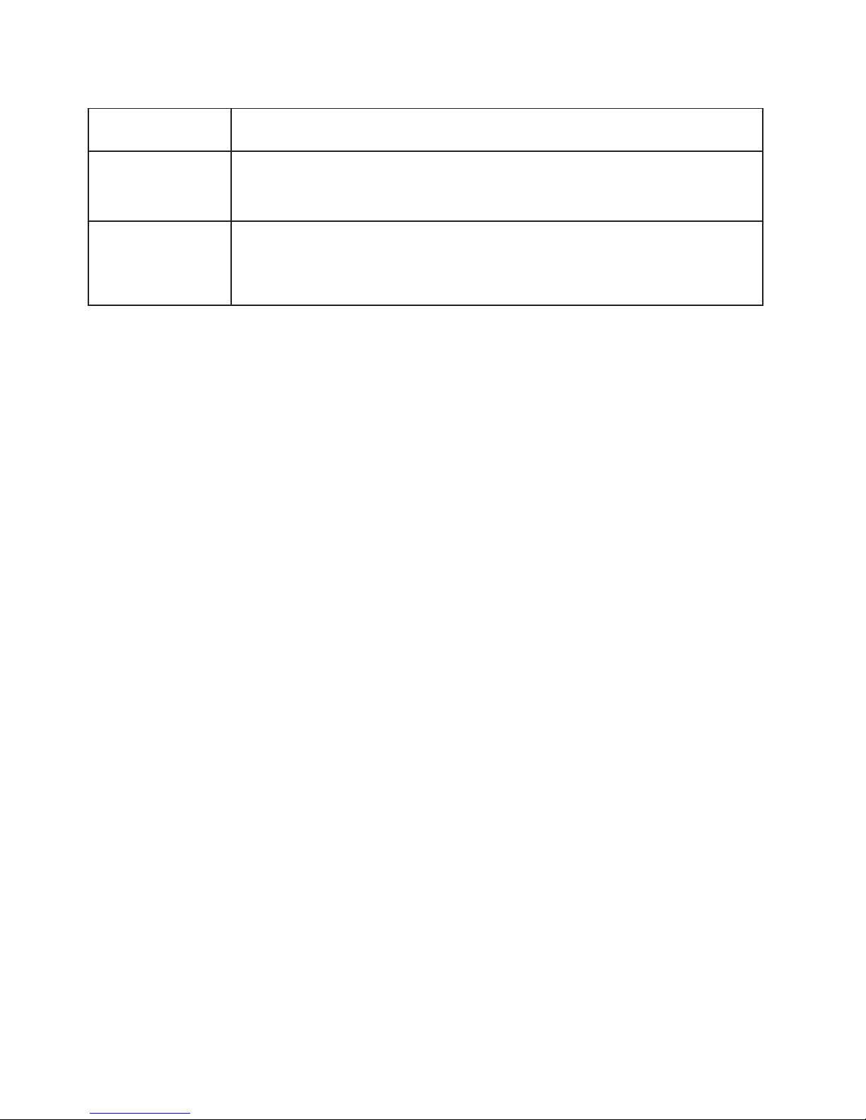
Problem Solution
Error Code
FFFF or FFFC
Gateway is connected but AC is not powered or the
communication to AC is lost.
Error Code
FFFE
Communication to gateway is lost. Gateway switch setting
issue or faulty gateway.
8. Troubleshooting
Troubleshooting
Page 65

65
Page 66

66
Page 67

67
Page 68

Polyaire Pty Ltd
11-13 White Road
Gepps Cross South Australia, 5094
Tel: (08) 8349 8466 Fax: (08) 8349 8446
© Polyaire Pty Ltd 2018
Liability and Disclaimer
All specications and procedures are correct at time
of publication, but are subject to change without
notice. Please read the instructions before installing
this Zone Control System. Polyaire Pty Ltd does not
accept any responsibility for loss or damage that
may occur as a result of the incorrect installation or
operation of this AirTouch Control System.
1300 980 656
airtouch
 Loading...