


DESIGN GUIDE
1.9.0 | September 2016 | 3725-33186-002A
Polycom® SoundStructure® C16, C12, C8,
and SR12

Copyright© 2016, Polycom, Inc. All rights reserved. No part of this document may be reproduced, translated into another
language or format, or transmitted in any form or by any means, electronic or mechanical, for any purpose, without the
express written permission of Polycom, Inc.
6001 America Center Drive
San Jose, CA 95002
USA
Trademarks Polycom
trademarks and/or service marks of Polycom, Inc., and are registered and/or common law marks in the United States
and various other countries.
All other trademarks are property of their respective owners. No portion hereof may be reproduced or transmitted in any
form or by any means, for any purpose other than the recipient's personal use, without the express written permission
of Polycom.
®
, the Polycom logo and the names and marks associated with Polycom products are
Disclaimer While Polycom uses reasonable efforts to include accurate and up-to-date information in this document,
Polycom makes no warranties or representations as to its accuracy. Polycom assumes no liability or responsibility for
any typographical or other errors or omissions in the content of this document.
Limitation of Liability Polycom and/or its respective suppliers make no representations about the suitability of the
information contained in this document for any purpose. Information is provided "as is" without warranty of any kind and
is subject to change without notice. The entire risk arising out of its use remains with the recipient. In no event shall
Polycom and/or its respective suppliers be liable for any direct, consequential, incidental, special, punitive or other
damages whatsoever (including without limitation, damages for loss of business profits, business interruption, or loss of
business information), even if Polycom has been advised of the possibility of such damages.
End User License Agreement By installing, copying, or otherwise using this product, you acknowledge that you
have read, understand and agree to be bound by the terms and conditions of the End User License Agreement for this
product. The EULA for this product is available on the Polycom Support page for the product.
Patent Information The accompanying product may be protected by one or more U.S. and foreign patents and/or
pending patent applications held by Polycom, Inc.
Open Source Software Used in this Product This product may contain open source software. You may receive
the open source software from Polycom up to three (3) years after the distribution date of the applicable product or
software at a charge not greater than the cost to Polycom of shipping or distributing the software to you. To receive
software information, as well as the open source software code used in this product, contact Polycom by email at
OpenSourceVideo@polycom.com.
Customer Feedback We are striving to improve our documentation quality and we appreciate your feedback. Email
your opinions and comments to DocumentationFeedback@polycom.com.
Polycom Support Visit the Polycom Support Center for End User License Agreements, software downloads,
product documents, product licenses, troubleshooting tips, service requests, and more.
2

Contents
Introduction . . . . . . . . . . . . . . . . . . . . . . . . . . . . . . . . . . . . . . . . . . . . . . . . . . . . . . . 14
Introducing the Polycom SoundStructure Product Family . . . . . . . . . . . . . . . . . 17
Defining SoundStructure Architectural Features . . . . . . . . . . . . . . . . . . . . . . . . . . . . . . . . . . . 17
Understanding Polycom OBAM™ - One Big Audio Matrix . . . . . . . . . . . . . . . . . . . . . . . . . . . 19
Understanding SoundStructure C-Series Products . . . . . . . . . . . . . . . . . . . . . . . . . . . . . . . . . 21
Understanding C-Series Input Processing . . . . . . . . . . . . . . . . . . . . . . . . . . . . . . . . . . . . 22
Creating C-Series Matrix Crosspoints . . . . . . . . . . . . . . . . . . . . . . . . . . . . . . . . . . . . . . . . 28
Understanding C-Series Output processing . . . . . . . . . . . . . . . . . . . . . . . . . . . . . . . . . . . 29
Processing C-Series Submixes . . . . . . . . . . . . . . . . . . . . . . . . . . . . . . . . . . . . . . . . . . . . . 30
Understanding C-Series Acoustic Echo Canceller References . . . . . . . . . . . . . . . . . . . . 31
Understanding SoundStructure SR-Series Products . . . . . . . . . . . . . . . . . . . . . . . . . . . . . . . . 32
Understanding SR-Series Input Processing . . . . . . . . . . . . . . . . . . . . . . . . . . . . . . . . . . . 34
Creating SR-Series Matrix Crosspoints . . . . . . . . . . . . . . . . . . . . . . . . . . . . . . . . . . . . . . 41
Understanding SR-Series Output Processing . . . . . . . . . . . . . . . . . . . . . . . . . . . . . . . . . . 42
Processing SR-Series Submix . . . . . . . . . . . . . . . . . . . . . . . . . . . . . . . . . . . . . . . . . . . . . 43
Understanding Telephony Processing . . . . . . . . . . . . . . . . . . . . . . . . . . . . . . . . . . . . . . . . . . . 44
Introducing SoundStructure Design Concepts . . . . . . . . . . . . . . . . . . . . . . . . . . 47
Understanding Device Inputs and Outputs . . . . . . . . . . . . . . . . . . . . . . . . . . . . . . . . . . . . . . . 47
Understanding Physical Channels . . . . . . . . . . . . . . . . . . . . . . . . . . . . . . . . . . . . . . . . . . . . . . 48
Numbering Physical Channel On A Single SoundStructure Device . . . . . . . . . . . . . . . . . 48
Numbering Physical Channel With Multiple SoundStructure Devices . . . . . . . . . . . . . . . 49
Physical Channel Summary . . . . . . . . . . . . . . . . . . . . . . . . . . . . . . . . . . . . . . . . . . . . . . . 55
Understanding Virtual Channels . . . . . . . . . . . . . . . . . . . . . . . . . . . . . . . . . . . . . . . . . . . . . . . 56
Virtual Channel Summary . . . . . . . . . . . . . . . . . . . . . . . . . . . . . . . . . . . . . . . . . . . . . . . . . 57
Understanding Virtual Channel Groups . . . . . . . . . . . . . . . . . . . . . . . . . . . . . . . . . . . . . . . . . . 58
Virtual Channel Group Summary . . . . . . . . . . . . . . . . . . . . . . . . . . . . . . . . . . . . . . . . . . . 62
Understanding Telephone Virtual Channels . . . . . . . . . . . . . . . . . . . . . . . . . . . . . . . . . . . . . . 62
Defining Logic Pins . . . . . . . . . . . . . . . . . . . . . . . . . . . . . . . . . . . . . . . . . . . . . . . . . . . . . . . . . 62
Labeling Physical Logic Pins . . . . . . . . . . . . . . . . . . . . . . . . . . . . . . . . . . . . . . . . . . . . . . . 63
Controlling Virtual Channels . . . . . . . . . . . . . . . . . . . . . . . . . . . . . . . . . . . . . . . . . . . . . . . 67
Polycom, Inc. 3

Design Guide for Polycom C16, C12, C8, and SR12 SoundStructure Studio 1.9.0
Controlling Array Virtual Channels . . . . . . . . . . . . . . . . . . . . . . . . . . . . . . . . . . . . . . . . . . 68
Understanding IR Receiver Virtual Channel . . . . . . . . . . . . . . . . . . . . . . . . . . . . . . . . . . . . . . 69
Creating Designs with SoundStructure Studio . . . . . . . . . . . . . . . . . . . . . . . . . . 70
Understanding SoundStructure Studio . . . . . . . . . . . . . . . . . . . . . . . . . . . . . . . . . . . . . . . . . . 70
Understanding System Requirements . . . . . . . . . . . . . . . . . . . . . . . . . . . . . . . . . . . . . . . 71
Viewing Recommended Operating System . . . . . . . . . . . . . . . . . . . . . . . . . . . . . . . . . . . 71
Installing SoundStructure Studio . . . . . . . . . . . . . . . . . . . . . . . . . . . . . . . . . . . . . . . . . . . . 71
Operating in Online and Offline Mode . . . . . . . . . . . . . . . . . . . . . . . . . . . . . . . . . . . . . . . . 77
Customizing SoundStructure Designs . . . . . . . . . . . . . . . . . . . . . . . . . . . . . . . . 80
Using the Wiring Page . . . . . . . . . . . . . . . . . . . . . . . . . . . . . . . . . . . . . . . . . . . . . . . . . . . . . . . 80
Editing Devices . . . . . . . . . . . . . . . . . . . . . . . . . . . . . . . . . . . . . . . . . . . . . . . . . . . . . . . . . 83
Using the Channels Page . . . . . . . . . . . . . . . . . . . . . . . . . . . . . . . . . . . . . . . . . . . . . . . . . . . . 84
Editing Virtual Channels . . . . . . . . . . . . . . . . . . . . . . . . . . . . . . . . . . . . . . . . . . . . . . . . . . 87
Creating Virtual Channel Groups . . . . . . . . . . . . . . . . . . . . . . . . . . . . . . . . . . . . . . . . . . . 88
Setting Input Signals . . . . . . . . . . . . . . . . . . . . . . . . . . . . . . . . . . . . . . . . . . . . . . . . . . . . . . . . 91
Enabling Input Signal Meters . . . . . . . . . . . . . . . . . . . . . . . . . . . . . . . . . . . . . . . . . . . . . . 92
Using Input Channel Controls . . . . . . . . . . . . . . . . . . . . . . . . . . . . . . . . . . . . . . . . . . . . . . 97
Operating Analog Signal Gain . . . . . . . . . . . . . . . . . . . . . . . . . . . . . . . . . . . . . . . . . . . . . . 98
Changing the Mute Status . . . . . . . . . . . . . . . . . . . . . . . . . . . . . . . . . . . . . . . . . . . . . . . . . 99
Enabling Phantom Power . . . . . . . . . . . . . . . . . . . . . . . . . . . . . . . . . . . . . . . . . . . . . . . . . 99
Using the Ungated Type . . . . . . . . . . . . . . . . . . . . . . . . . . . . . . . . . . . . . . . . . . . . . . . . . 100
Using Delay Type . . . . . . . . . . . . . . . . . . . . . . . . . . . . . . . . . . . . . . . . . . . . . . . . . . . . . . 104
Using Delay Compensation . . . . . . . . . . . . . . . . . . . . . . . . . . . . . . . . . . . . . . . . . . . . . . . 106
Using Trim . . . . . . . . . . . . . . . . . . . . . . . . . . . . . . . . . . . . . . . . . . . . . . . . . . . . . . . . . . . . 107
Processing Equalization . . . . . . . . . . . . . . . . . . . . . . . . . . . . . . . . . . . . . . . . . . . . . . . . . 108
Eliminating Feedback . . . . . . . . . . . . . . . . . . . . . . . . . . . . . . . . . . . . . . . . . . . . . . . . . . . 110
Enabling Acoustic Echo Cancellation (AEC) . . . . . . . . . . . . . . . . . . . . . . . . . . . . . . . . . . 112
Processing Noise Cancellation . . . . . . . . . . . . . . . . . . . . . . . . . . . . . . . . . . . . . . . . . . . . 113
Using Automatic Gain Control (AGC) . . . . . . . . . . . . . . . . . . . . . . . . . . . . . . . . . . . . . . . 115
Using Dynamics Processors . . . . . . . . . . . . . . . . . . . . . . . . . . . . . . . . . . . . . . . . . . . . . . 116
Using Automatic Microphone Mixing . . . . . . . . . . . . . . . . . . . . . . . . . . . . . . . . . . . . . . . . 121
Processing Delay . . . . . . . . . . . . . . . . . . . . . . . . . . . . . . . . . . . . . . . . . . . . . . . . . . . . . . 125
Controlling Fader . . . . . . . . . . . . . . . . . . . . . . . . . . . . . . . . . . . . . . . . . . . . . . . . . . . . . . . 125
Defining a Signal Generator . . . . . . . . . . . . . . . . . . . . . . . . . . . . . . . . . . . . . . . . . . . . . . . . . 126
Setting Output Signals . . . . . . . . . . . . . . . . . . . . . . . . . . . . . . . . . . . . . . . . . . . . . . . . . . . . . . 128
Processing Output Dynamics . . . . . . . . . . . . . . . . . . . . . . . . . . . . . . . . . . . . . . . . . . . . . 129
Processing Output Equalization . . . . . . . . . . . . . . . . . . . . . . . . . . . . . . . . . . . . . . . . . . . 129
Processing Delay . . . . . . . . . . . . . . . . . . . . . . . . . . . . . . . . . . . . . . . . . . . . . . . . . . . . . . 131
Polycom, Inc. 4

Design Guide for Polycom C16, C12, C8, and SR12 SoundStructure Studio 1.9.0
Processing Submix Signals . . . . . . . . . . . . . . . . . . . . . . . . . . . . . . . . . . . . . . . . . . . . . . . . . . 131
Processing Output Dynamics . . . . . . . . . . . . . . . . . . . . . . . . . . . . . . . . . . . . . . . . . . . . . 132
Processing Output Equalization . . . . . . . . . . . . . . . . . . . . . . . . . . . . . . . . . . . . . . . . . . . 132
Processing Delay . . . . . . . . . . . . . . . . . . . . . . . . . . . . . . . . . . . . . . . . . . . . . . . . . . . . . . 134
Controlling Fader . . . . . . . . . . . . . . . . . . . . . . . . . . . . . . . . . . . . . . . . . . . . . . . . . . . . . . . 134
Using the Matrix Page . . . . . . . . . . . . . . . . . . . . . . . . . . . . . . . . . . . . . . . . . . . . . . . . . . . . . . 134
Adjusting Crosspoints . . . . . . . . . . . . . . . . . . . . . . . . . . . . . . . . . . . . . . . . . . . . . . . . . . . 136
Matrix summary . . . . . . . . . . . . . . . . . . . . . . . . . . . . . . . . . . . . . . . . . . . . . . . . . . . . . . . . 141
Using the Telephony Channels . . . . . . . . . . . . . . . . . . . . . . . . . . . . . . . . . . . . . . . . . . . . . . . 142
Adjusting Input Gain . . . . . . . . . . . . . . . . . . . . . . . . . . . . . . . . . . . . . . . . . . . . . . . . . . . . 143
Processing Noise Cancellation . . . . . . . . . . . . . . . . . . . . . . . . . . . . . . . . . . . . . . . . . . . . 144
Using Automatic Gain Control (AGC) . . . . . . . . . . . . . . . . . . . . . . . . . . . . . . . . . . . . . . . 144
Processing Output Dynamics . . . . . . . . . . . . . . . . . . . . . . . . . . . . . . . . . . . . . . . . . . . . . 145
Processing Equalization . . . . . . . . . . . . . . . . . . . . . . . . . . . . . . . . . . . . . . . . . . . . . . . . . 145
Controlling Fader . . . . . . . . . . . . . . . . . . . . . . . . . . . . . . . . . . . . . . . . . . . . . . . . . . . . . . . 146
Processing Delay . . . . . . . . . . . . . . . . . . . . . . . . . . . . . . . . . . . . . . . . . . . . . . . . . . . . . . 146
Using Telephone Controls . . . . . . . . . . . . . . . . . . . . . . . . . . . . . . . . . . . . . . . . . . . . . . . . 147
Connecting Over Conference Link2 . . . . . . . . . . . . . . . . . . . . . . . . . . . . . . . . . . 150
Connecting SoundStructure Conference Link2 . . . . . . . . . . . . . . . . . . . . . . . . . . . . . . . . . . . 150
Integrating Polycom Video Codec . . . . . . . . . . . . . . . . . . . . . . . . . . . . . . . . . . . . . . . . . . . . . 151
Designing with The Polycom Video Codec . . . . . . . . . . . . . . . . . . . . . . . . . . . . . . . . . . . . . . 153
Editing The Polycom Video Codec Input Channels . . . . . . . . . . . . . . . . . . . . . . . . . . . . 153
Processing The Polycom Video Codec SoundStructure Signals . . . . . . . . . . . . . . . . . . 156
Understanding The Polycom Video Codec Output Channels . . . . . . . . . . . . . . . . . . . . . 157
Routing The Polycom Video Codec Signals . . . . . . . . . . . . . . . . . . . . . . . . . . . . . . . . . . 158
Using the Mute Controls . . . . . . . . . . . . . . . . . . . . . . . . . . . . . . . . . . . . . . . . . . . . . . . . . 159
Using the Volume Controls . . . . . . . . . . . . . . . . . . . . . . . . . . . . . . . . . . . . . . . . . . . . . . . 161
Designing With Polycom Digital Microphone Arrays . . . . . . . . . . . . . . . . . . . . . . . . . . . . . . . 163
Understanding Digital Microphone Cabling Requirements . . . . . . . . . . . . . . . . . . . . . . . 164
Updating Digital Microphone Firmware . . . . . . . . . . . . . . . . . . . . . . . . . . . . . . . . . . . . . . 164
Detecting CLink2 Devices . . . . . . . . . . . . . . . . . . . . . . . . . . . . . . . . . . . . . . . . . . . . . . . . 166
Viewing Digital Microphone Array Example . . . . . . . . . . . . . . . . . . . . . . . . . . . . . . . . . . 166
Assigning Digital Microphone Array Channels To Physical Inputs . . . . . . . . . . . . . . . . . 169
Numbering Digital Microphone Array . . . . . . . . . . . . . . . . . . . . . . . . . . . . . . . . . . . . . . . 172
Understanding Installation Options . . . . . . . . . . . . . . . . . . . . . . . . . . . . . . . . . . . . . . . . . . . . 174
Summary . . . . . . . . . . . . . . . . . . . . . . . . . . . . . . . . . . . . . . . . . . . . . . . . . . . . . . . . . . . . . . . . 177
Linking Multiple SoundStructure Devices with One Big Audio Matrix . . . . . . 179
Introduction . . . . . . . . . . . . . . . . . . . . . . . . . . . . . . . . . . . . . . . . . . . . . . . . . . . . . . . . . . . . . . 179
Polycom, Inc. 5

Design Guide for Polycom C16, C12, C8, and SR12 SoundStructure Studio 1.9.0
Preparing Units for Linking with OBAM . . . . . . . . . . . . . . . . . . . . . . . . . . . . . . . . . . . . . . . . . 179
Updating SoundStructure Device Firmwa re . . . . . . . . . . . . . . . . . . . . . . . . . . . . . . . . . . 179
Linking SoundStructure Devices . . . . . . . . . . . . . . . . . . . . . . . . . . . . . . . . . . . . . . . . . . . 180
Creating a Multi-Device Configuration File . . . . . . . . . . . . . . . . . . . . . . . . . . . . . . . . . . . . . . 184
Expanding or Contracting an Existing Project . . . . . . . . . . . . . . . . . . . . . . . . . . . . . . . . . 185
Creating a New Project . . . . . . . . . . . . . . . . . . . . . . . . . . . . . . . . . . . . . . . . . . . . . . . . . . 187
Uploading Configuration Files . . . . . . . . . . . . . . . . . . . . . . . . . . . . . . . . . . . . . . . . . . . . . . . . 190
Controlling the SoundStructure System . . . . . . . . . . . . . . . . . . . . . . . . . . . . . . . . . . . . . 193
Accessing SoundStructure Logs . . . . . . . . . . . . . . . . . . . . . . . . . . . . . . . . . . . . . . . . . . . 194
Connecting Polycom Microphones . . . . . . . . . . . . . . . . . . . . . . . . . . . . . . . . . . . . . . . . . 195
Connecting Multiple Polycom Video Codec Conferencing Systems . . . . . . . . . . . . . . . . 198
Installing SoundStructure Devices . . . . . . . . . . . . . . . . . . . . . . . . . . . . . . . . . . . 201
Configuration Files . . . . . . . . . . . . . . . . . . . . . . . . . . . . . . . . . . . . . . . . . . . . . . . . . . . . . . . . . 201
Wiring The Devices . . . . . . . . . . . . . . . . . . . . . . . . . . . . . . . . . . . . . . . . . . . . . . . . . . . . . . . . 201
Uploading A Configuration File . . . . . . . . . . . . . . . . . . . . . . . . . . . . . . . . . . . . . . . . . . . . . . . 205
Downloading A Configuration File . . . . . . . . . . . . . . . . . . . . . . . . . . . . . . . . . . . . . . . . . . . . . 209
Updating Firmware . . . . . . . . . . . . . . . . . . . . . . . . . . . . . . . . . . . . . . . . . . . . . . . . . . . . . . . . 209
Configuring The Signal Gains . . . . . . . . . . . . . . . . . . . . . . . . . . . . . . . . . . . . . . . . . . . . . . . . 211
Input Signal Level Adjustment . . . . . . . . . . . . . . . . . . . . . . . . . . . . . . . . . . . . . . . . . . . . . 212
Signal Meters . . . . . . . . . . . . . . . . . . . . . . . . . . . . . . . . . . . . . . . . . . . . . . . . . . . . . . . . . 212
Room Gain . . . . . . . . . . . . . . . . . . . . . . . . . . . . . . . . . . . . . . . . . . . . . . . . . . . . . . . . . . . 214
Telephony Signal Levels . . . . . . . . . . . . . . . . . . . . . . . . . . . . . . . . . . . . . . . . . . . . . . . . . 216
Output Signal Levels . . . . . . . . . . . . . . . . . . . . . . . . . . . . . . . . . . . . . . . . . . . . . . . . . . . . 218
Presets . . . . . . . . . . . . . . . . . . . . . . . . . . . . . . . . . . . . . . . . . . . . . . . . . . . . . . . . . . . . . . . . . 223
Preset Operation . . . . . . . . . . . . . . . . . . . . . . . . . . . . . . . . . . . . . . . . . . . . . . . . . . . . . . . 224
Saving Presets . . . . . . . . . . . . . . . . . . . . . . . . . . . . . . . . . . . . . . . . . . . . . . . . . . . . . . . . 225
Creating Partial Presets . . . . . . . . . . . . . . . . . . . . . . . . . . . . . . . . . . . . . . . . . . . . . . . . . 227
Running Presets . . . . . . . . . . . . . . . . . . . . . . . . . . . . . . . . . . . . . . . . . . . . . . . . . . . . . . . 231
Removing Presets . . . . . . . . . . . . . . . . . . . . . . . . . . . . . . . . . . . . . . . . . . . . . . . . . . . . . . 232
Using Events, Logic, and IR . . . . . . . . . . . . . . . . . . . . . . . . . . . . . . . . . . . . . . . . . 233
Understanding Events . . . . . . . . . . . . . . . . . . . . . . . . . . . . . . . . . . . . . . . . . . . . . . . . . . . . . . 233
Sources . . . . . . . . . . . . . . . . . . . . . . . . . . . . . . . . . . . . . . . . . . . . . . . . . . . . . . . . . . . . . . 233
Triggers . . . . . . . . . . . . . . . . . . . . . . . . . . . . . . . . . . . . . . . . . . . . . . . . . . . . . . . . . . . . . . 234
Actions . . . . . . . . . . . . . . . . . . . . . . . . . . . . . . . . . . . . . . . . . . . . . . . . . . . . . . . . . . . . . . 234
Creating Events With SoundStructure Studio . . . . . . . . . . . . . . . . . . . . . . . . . . . . . . . . . . . . 236
Adding New Events . . . . . . . . . . . . . . . . . . . . . . . . . . . . . . . . . . . . . . . . . . . . . . . . . . . . . 236
Enable And Disable Events . . . . . . . . . . . . . . . . . . . . . . . . . . . . . . . . . . . . . . . . . . . . . . . 236
Event Entries In The Logs . . . . . . . . . . . . . . . . . . . . . . . . . . . . . . . . . . . . . . . . . . . . . . . . 237
Polycom, Inc. 6

Design Guide for Polycom C16, C12, C8, and SR12 SoundStructure Studio 1.9.0
Removing Events With Studio . . . . . . . . . . . . . . . . . . . . . . . . . . . . . . . . . . . . . . . . . . . . . 238
SoundStructure Studio Automatically Creates Events . . . . . . . . . . . . . . . . . . . . . . . . . . 238
Polycom IR Remote . . . . . . . . . . . . . . . . . . . . . . . . . . . . . . . . . . . . . . . . . . . . . . . . . . . . . . . . 242
Polycom IR Remote Channel ID . . . . . . . . . . . . . . . . . . . . . . . . . . . . . . . . . . . . . . . . . . . 246
IR Receiver Connector . . . . . . . . . . . . . . . . . . . . . . . . . . . . . . . . . . . . . . . . . . . . . . . . . . 246
Logic Ports . . . . . . . . . . . . . . . . . . . . . . . . . . . . . . . . . . . . . . . . . . . . . . . . . . . . . . . . . . . . . . . 247
Digital Logic Inputs . . . . . . . . . . . . . . . . . . . . . . . . . . . . . . . . . . . . . . . . . . . . . . . . . . . . . 248
Analog Logic Inputs . . . . . . . . . . . . . . . . . . . . . . . . . . . . . . . . . . . . . . . . . . . . . . . . . . . . . 250
Logic Outputs . . . . . . . . . . . . . . . . . . . . . . . . . . . . . . . . . . . . . . . . . . . . . . . . . . . . . . . . . 250
Logic Arrays . . . . . . . . . . . . . . . . . . . . . . . . . . . . . . . . . . . . . . . . . . . . . . . . . . . . . . . . . . 251
Viewing Event Examples . . . . . . . . . . . . . . . . . . . . . . . . . . . . . . . . . . . . . . . . . . . . . . . . . . . . 253
Splitting and Combining Presets Triggered from a Logic Input . . . . . . . . . . . . . . . . . . . . 253
Viewing Push To Talk Microphones with LEDs Example . . . . . . . . . . . . . . . . . . . . . . . . 256
Viewing Push and Hold to Temporarily Mute A Microphone . . . . . . . . . . . . . . . . . . . . . . 260
Viewing the Phone Off Hook Drives A Relay Example . . . . . . . . . . . . . . . . . . . . . . . . . . 261
Viewing the Volume Knob Adjusts “Amplifier” Fader Example . . . . . . . . . . . . . . . . . . . . 263
Viewing the Gating Information Sent To A Control System Example . . . . . . . . . . . . . . . 265
Positioning A Polycom Video Codec Camera Example . . . . . . . . . . . . . . . . . . . . . . . . . 267
Creating SoundStructure Events Best Practices . . . . . . . . . . . . . . . . . . . . . . . . . . . . . . . . . . 268
Managing SoundStructure Systems . . . . . . . . . . . . . . . . . . . . . . . . . . . . . . . . . 270
Connecting To The Device . . . . . . . . . . . . . . . . . . . . . . . . . . . . . . . . . . . . . . . . . . . . . . . . . . 270
LAN Interface . . . . . . . . . . . . . . . . . . . . . . . . . . . . . . . . . . . . . . . . . . . . . . . . . . . . . . . . . . . . . 270
Dynamic IP Addresses . . . . . . . . . . . . . . . . . . . . . . . . . . . . . . . . . . . . . . . . . . . . . . . . . . 271
Link-Local IP Addresses . . . . . . . . . . . . . . . . . . . . . . . . . . . . . . . . . . . . . . . . . . . . . . . . . 273
Static IP Addresses . . . . . . . . . . . . . . . . . . . . . . . . . . . . . . . . . . . . . . . . . . . . . . . . . . . . . 274
Setting The Time Server . . . . . . . . . . . . . . . . . . . . . . . . . . . . . . . . . . . . . . . . . . . . . . . . . 276
Control And Command Sessions . . . . . . . . . . . . . . . . . . . . . . . . . . . . . . . . . . . . . . . . . . 276
SoundStructure Device Discovery . . . . . . . . . . . . . . . . . . . . . . . . . . . . . . . . . . . . . . . . . 278
AMX Beacon . . . . . . . . . . . . . . . . . . . . . . . . . . . . . . . . . . . . . . . . . . . . . . . . . . . . . . . . . . 278
RS-232 . . . . . . . . . . . . . . . . . . . . . . . . . . . . . . . . . . . . . . . . . . . . . . . . . . . . . . . . . . . . . . . . . 279
Configuring And Accessing The Logs . . . . . . . . . . . . . . . . . . . . . . . . . . . . . . . . . . . . . . . . . . 279
Using the Polycom® RealPresence Touch™ with a SoundStructure System . 281
Setting Up and Enabling the RealPresence Touch . . . . . . . . . . . . . . . . . . . . . . . . . . . . . . . . 281
Pairing the RealPresence Touch Device with a SoundStructure System . . . . . . . . . . . . . . . 281
Placing Calls on the RealPresence Touch . . . . . . . . . . . . . . . . . . . . . . . . . . . . . . . . . . . . . . 282
Use the RealPresence Touch to Generate Touch Tones in a SoundStructure Call . . . . . . . 282
Use the RealPresence Touch to Generate a Flash Hook Command . . . . . . . . . . . . . . . . . . 283
Polycom, Inc. 7

Design Guide for Polycom C16, C12, C8, and SR12 SoundStructure Studio 1.9.0
Integrating The Polycom® Touch Control with SoundStructure Systems . . . 284
Polycom Touch Control and SoundStructure Systems . . . . . . . . . . . . . . . . . . . . . . . . . . . . . 284
SoundStructure System Requirements . . . . . . . . . . . . . . . . . . . . . . . . . . . . . . . . . . . . . . 284
Using a Polycom Touch Control with Video Codec Systems Versus SoundStructure Systems
285
Pairing the Polycom Touch Control with SoundStructure . . . . . . . . . . . . . . . . . . . . . . . . . . . 286
Polycom Touch Control Administrative Settings . . . . . . . . . . . . . . . . . . . . . . . . . . . . . . . 290
Configuring the Polycom Touch Control LAN Properties . . . . . . . . . . . . . . . . . . . . . . . . 291
Configuring Polycom Touch Control Regional Settings . . . . . . . . . . . . . . . . . . . . . . . . . 292
Configuring Security Options . . . . . . . . . . . . . . . . . . . . . . . . . . . . . . . . . . . . . . . . . . . . . 293
Setting up Polycom Touch Control log management . . . . . . . . . . . . . . . . . . . . . . . . . . . 293
Updating Polycom Touch Control Software . . . . . . . . . . . . . . . . . . . . . . . . . . . . . . . . . . 293
Using the Polycom Touch Control with SoundStructure . . . . . . . . . . . . . . . . . . . . . . . . . . . . 295
Designing a SoundStructure Project with the Polycom Touch Control . . . . . . . . . . . . . . 295
Using Multiple SoundStructure Telephony Interfaces . . . . . . . . . . . . . . . . . . . . . . . . . . . 299
Using Multiple Polycom Touch Controls with SoundStructure . . . . . . . . . . . . . . . . . . . . 300
Validating Polycom Touch Control and SoundStructure integration . . . . . . . . . . . . . . . . 301
Integrating SoundStructure with SoundStructure VoIP Interface . . . . . . . . . . 305
Introduction . . . . . . . . . . . . . . . . . . . . . . . . . . . . . . . . . . . . . . . . . . . . . . . . . . . . . . . . . . . . . . 305
How to Read This Chapter . . . . . . . . . . . . . . . . . . . . . . . . . . . . . . . . . . . . . . . . . . . . . . . 306
SoundStructure VoIP Interface Overview . . . . . . . . . . . . . . . . . . . . . . . . . . . . . . . . . . . . 306
SoundStructure System Requirements . . . . . . . . . . . . . . . . . . . . . . . . . . . . . . . . . . . . . . 308
Upgrading a Project to the SoundStructure VoIP Interface . . . . . . . . . . . . . . . . . . . . . . . . . . 308
Upgrading an Existing TEL1/TEL2 Project to the SoundStructure VoIP Interface . . . . . 309
Creating a New Project with the SoundStructure VoIP interface . . . . . . . . . . . . . . . . . . 316
Upgrading the Firmware in the SoundStructu re Syste m . . . . . . . . . . . . . . . . . . . . . . . . . 322
Installing the New Plugin Cards . . . . . . . . . . . . . . . . . . . . . . . . . . . . . . . . . . . . . . . . . . . 324
Uploading the Configuration File . . . . . . . . . . . . . . . . . . . . . . . . . . . . . . . . . . . . . . . . . . . 326
Configuring the SoundStructure VoIP Interface . . . . . . . . . . . . . . . . . . . . . . . . . . . . . . . . . . 327
Setting the IP address of the SoundStructure VoIP Interface . . . . . . . . . . . . . . . . . . . . . 327
Setting the Provisioning Server settings . . . . . . . . . . . . . . . . . . . . . . . . . . . . . . . . . . . . . 333
Registering Lines with the SoundStructure VoIP Interface . . . . . . . . . . . . . . . . . . . . . . . 339
Using the SoundStructure VoIP Interface with SoundStructure Studio . . . . . . . . . . . . . . . . . 344
Using the Phone Settings Control . . . . . . . . . . . . . . . . . . . . . . . . . . . . . . . . . . . . . . . . . . 344
Customizing SoundStructure Telephony Settings . . . . . . . . . . . . . . . . . . . . . . . . . . . . . . 347
SoundStructure VoIP Interface Settings on the Wiring Page . . . . . . . . . . . . . . . . . . . . . 348
Setting an IP address with SoundStructure Studio . . . . . . . . . . . . . . . . . . . . . . . . . . . . . 349
Using the SoundStructure Studio Console . . . . . . . . . . . . . . . . . . . . . . . . . . . . . . . . . . . 352
Updating Software on the SoundStructure VoIP Interface . . . . . . . . . . . . . . . . . . . . . . . . . . 354
Polycom, Inc. 8

Design Guide for Polycom C16, C12, C8, and SR12 SoundStructure Studio 1.9.0
Upgrading Software with a Local FTP Server . . . . . . . . . . . . . . . . . . . . . . . . . . . . . . . . . 354
Upgrading Software with an Existing Provisioning Server . . . . . . . . . . . . . . . . . . . . . . . 355
Upgrading Software with the Web Configuration Utility . . . . . . . . . . . . . . . . . . . . . . . . . 357
Validating a SoundStructure VoIP Interface Installation . . . . . . . . . . . . . . . . . . . . . . . . . . . . 364
VoIP Interface Logs . . . . . . . . . . . . . . . . . . . . . . . . . . . . . . . . . . . . . . . . . . . . . . . . . . . . . 372
Back up and Restore the VoIP Specific Settings . . . . . . . . . . . . . . . . . . . . . . . . . . . . . . 374
Importing and Exporting VoIP Parameter Settings . . . . . . . . . . . . . . . . . . . . . . . . . . . . . 376
SoundStructure Log Information . . . . . . . . . . . . . . . . . . . . . . . . . . . . . . . . . . . . . . . . . . . 377
Information Required for Support . . . . . . . . . . . . . . . . . . . . . . . . . . . . . . . . . . . . . . . . . . . . . 379
Understanding SoundStructure VoIP Interface API Commands . . . . . . . . . . . . . . . . . . . . . . 379
Using the SoundStructure API . . . . . . . . . . . . . . . . . . . . . . . . . . . . . . . . . . . . . . . . . . . . . . . . 382
Dialing a Call . . . . . . . . . . . . . . . . . . . . . . . . . . . . . . . . . . . . . . . . . . . . . . . . . . . . . . . . . . 382
Hanging up a Call . . . . . . . . . . . . . . . . . . . . . . . . . . . . . . . . . . . . . . . . . . . . . . . . . . . . . . 383
Putting a Call on Hold and Resuming the Call . . . . . . . . . . . . . . . . . . . . . . . . . . . . . . . . 383
Forwarding an Incoming Call . . . . . . . . . . . . . . . . . . . . . . . . . . . . . . . . . . . . . . . . . . . . . 384
Transferring a Call . . . . . . . . . . . . . . . . . . . . . . . . . . . . . . . . . . . . . . . . . . . . . . . . . . . . . . 384
Blind Transfer of a Call . . . . . . . . . . . . . . . . . . . . . . . . . . . . . . . . . . . . . . . . . . . . . . . . . . 385
Dialing Two Calls on the Same Line . . . . . . . . . . . . . . . . . . . . . . . . . . . . . . . . . . . . . . . . 386
Dialing Two Calls on Different Lines . . . . . . . . . . . . . . . . . . . . . . . . . . . . . . . . . . . . . . . . 387
SoundStructure API Behavior Changes . . . . . . . . . . . . . . . . . . . . . . . . . . . . . . . . . . . . . 388
Adding Authentication to SoundStructure Systems . . . . . . . . . . . . . . . . . . . . . 390
SoundStructure Authentication Overview . . . . . . . . . . . . . . . . . . . . . . . . . . . . . . . . . . . . . . . 390
SoundStructure System Requirements . . . . . . . . . . . . . . . . . . . . . . . . . . . . . . . . . . . . . . . . . 390
Enabling Authentication on a SoundStructure System . . . . . . . . . . . . . . . . . . . . . . . . . . . . . 391
Discovering a System with Authentication . . . . . . . . . . . . . . . . . . . . . . . . . . . . . . . . . . . . . . . 392
Removing Authentication from a SoundStructure System . . . . . . . . . . . . . . . . . . . . . . . . . . 394
Viewing SoundStructure Command Logs . . . . . . . . . . . . . . . . . . . . . . . . . . . . . . . . . . . . . . . 395
Understanding SoundStructure System Compatibility Considerations . . . . . . . . . . . . . . . . . 395
SoundStructure Authentication API Command Summary . . . . . . . . . . . . . . . . . . . . . . . . 398
Creating Advanced Applications . . . . . . . . . . . . . . . . . . . . . . . . . . . . . . . . . . . . . 400
Creating a One Microphone And Mono Video Conferencing System . . . . . . . . . . . . . . . . . . 400
SoundStructure Studio Steps . . . . . . . . . . . . . . . . . . . . . . . . . . . . . . . . . . . . . . . . . . . . . 401
Using the Channels Page . . . . . . . . . . . . . . . . . . . . . . . . . . . . . . . . . . . . . . . . . . . . . . . . 404
Using the Matrix Page . . . . . . . . . . . . . . . . . . . . . . . . . . . . . . . . . . . . . . . . . . . . . . . . . . . 405
Understanding Wiring Information . . . . . . . . . . . . . . . . . . . . . . . . . . . . . . . . . . . . . . . . . . 406
Controlling The System . . . . . . . . . . . . . . . . . . . . . . . . . . . . . . . . . . . . . . . . . . . . . . . . . . 407
Creating Four Digital Array Microphones and A SoundStation VTX1000 Conferencing System .
408
SoundStructure Studio Steps . . . . . . . . . . . . . . . . . . . . . . . . . . . . . . . . . . . . . . . . . . . . . 410
Polycom, Inc. 9

Design Guide for Polycom C16, C12, C8, and SR12 SoundStructure Studio 1.9.0
Editing Matrix Settings . . . . . . . . . . . . . . . . . . . . . . . . . . . . . . . . . . . . . . . . . . . . . . . . . . 413
Editing Channels Settings . . . . . . . . . . . . . . . . . . . . . . . . . . . . . . . . . . . . . . . . . . . . . . . . 415
Understanding Wiring Information . . . . . . . . . . . . . . . . . . . . . . . . . . . . . . . . . . . . . . . . . . 418
Controlling The System . . . . . . . . . . . . . . . . . . . . . . . . . . . . . . . . . . . . . . . . . . . . . . . . . . 419
Creating an Eight Microphones, Video, and Telephony Application Conferencing System . 420
Creating a Project in SoundStructure Studio . . . . . . . . . . . . . . . . . . . . . . . . . . . . . . . . . 421
Matrix Settings . . . . . . . . . . . . . . . . . . . . . . . . . . . . . . . . . . . . . . . . . . . . . . . . . . . . . . . . 425
Channels Settings . . . . . . . . . . . . . . . . . . . . . . . . . . . . . . . . . . . . . . . . . . . . . . . . . . . . . . 427
Wiring Information . . . . . . . . . . . . . . . . . . . . . . . . . . . . . . . . . . . . . . . . . . . . . . . . . . . . . . 428
Controlling The System . . . . . . . . . . . . . . . . . . . . . . . . . . . . . . . . . . . . . . . . . . . . . . . . . . 429
Creating a Two PSTN Line Positional “Receive” Audio Conferencing System . . . . . . . . . . . 430
SoundStructure Studio Steps . . . . . . . . . . . . . . . . . . . . . . . . . . . . . . . . . . . . . . . . . . . . . 432
Matrix Settings . . . . . . . . . . . . . . . . . . . . . . . . . . . . . . . . . . . . . . . . . . . . . . . . . . . . . . . . 436
Channels Settings . . . . . . . . . . . . . . . . . . . . . . . . . . . . . . . . . . . . . . . . . . . . . . . . . . . . . . 439
Wiring Information . . . . . . . . . . . . . . . . . . . . . . . . . . . . . . . . . . . . . . . . . . . . . . . . . . . . . . 440
Controlling The System . . . . . . . . . . . . . . . . . . . . . . . . . . . . . . . . . . . . . . . . . . . . . . . . . . 441
Creating an Eight Microphones and Stereo Video Conferencing System . . . . . . . . . . . . . . . 443
Channels Settings . . . . . . . . . . . . . . . . . . . . . . . . . . . . . . . . . . . . . . . . . . . . . . . . . . . . . . 448
Wiring Information . . . . . . . . . . . . . . . . . . . . . . . . . . . . . . . . . . . . . . . . . . . . . . . . . . . . . . 449
Controlling The System . . . . . . . . . . . . . . . . . . . . . . . . . . . . . . . . . . . . . . . . . . . . . . . . . . 450
Creating an Eight Microphones with The Polycom Video Codec Conferencing System . . . . 451
SoundStructure Studio Steps . . . . . . . . . . . . . . . . . . . . . . . . . . . . . . . . . . . . . . . . . . . . . 451
Matrix Settings . . . . . . . . . . . . . . . . . . . . . . . . . . . . . . . . . . . . . . . . . . . . . . . . . . . . . . . . 455
Channels Settings . . . . . . . . . . . . . . . . . . . . . . . . . . . . . . . . . . . . . . . . . . . . . . . . . . . . . . 456
Wiring Information . . . . . . . . . . . . . . . . . . . . . . . . . . . . . . . . . . . . . . . . . . . . . . . . . . . . . . 457
Controlling The System . . . . . . . . . . . . . . . . . . . . . . . . . . . . . . . . . . . . . . . . . . . . . . . . . . 458
Creating an Eight Microphones with Wireless and Lectern Microphones Reinforcement Confer-
encing System . . . . . . . . . . . . . . . . . . . . . . . . . . . . . . . . . . . . . . . . . . . . . . . . . . . . . . . . . . 459
SoundStructure Studio Steps . . . . . . . . . . . . . . . . . . . . . . . . . . . . . . . . . . . . . . . . . . . . . 461
Matrix Settings . . . . . . . . . . . . . . . . . . . . . . . . . . . . . . . . . . . . . . . . . . . . . . . . . . . . . . . . 462
Channels Settings . . . . . . . . . . . . . . . . . . . . . . . . . . . . . . . . . . . . . . . . . . . . . . . . . . . . . . 465
Wiring Information . . . . . . . . . . . . . . . . . . . . . . . . . . . . . . . . . . . . . . . . . . . . . . . . . . . . . . 473
Controlling The System . . . . . . . . . . . . . . . . . . . . . . . . . . . . . . . . . . . . . . . . . . . . . . . . . . 474
Creating a Sixteen Microphones with Six-Zone Sound Reinforcement Conferencing System . . .
475
SoundStructure Studio Steps . . . . . . . . . . . . . . . . . . . . . . . . . . . . . . . . . . . . . . . . . . . . . 476
Matrix Settings . . . . . . . . . . . . . . . . . . . . . . . . . . . . . . . . . . . . . . . . . . . . . . . . . . . . . . . . 481
Channels Settings . . . . . . . . . . . . . . . . . . . . . . . . . . . . . . . . . . . . . . . . . . . . . . . . . . . . . . 484
Wiring Information . . . . . . . . . . . . . . . . . . . . . . . . . . . . . . . . . . . . . . . . . . . . . . . . . . . . . . 486
Controlling The System . . . . . . . . . . . . . . . . . . . . . . . . . . . . . . . . . . . . . . . . . . . . . . . . . . 488
Polycom, Inc. 10

Design Guide for Polycom C16, C12, C8, and SR12 SoundStructure Studio 1.9.0
Creating a Room Combining Application Conferencing System . . . . . . . . . . . . . . . . . . . . . . 488
SoundStructure Studio Steps . . . . . . . . . . . . . . . . . . . . . . . . . . . . . . . . . . . . . . . . . . . . . 491
Combined Room Settings . . . . . . . . . . . . . . . . . . . . . . . . . . . . . . . . . . . . . . . . . . . . . . . . 495
Split Room Settings . . . . . . . . . . . . . . . . . . . . . . . . . . . . . . . . . . . . . . . . . . . . . . . . . . . . . 499
Wiring Information . . . . . . . . . . . . . . . . . . . . . . . . . . . . . . . . . . . . . . . . . . . . . . . . . . . . . . 503
Controlling The System . . . . . . . . . . . . . . . . . . . . . . . . . . . . . . . . . . . . . . . . . . . . . . . . . . 504
Troubleshooting . . . . . . . . . . . . . . . . . . . . . . . . . . . . . . . . . . . . . . . . . . . . . . . . . . 506
Audio Troubleshooting . . . . . . . . . . . . . . . . . . . . . . . . . . . . . . . . . . . . . . . . . . . . . . . . . . . . . . 506
Echo Troubleshooting . . . . . . . . . . . . . . . . . . . . . . . . . . . . . . . . . . . . . . . . . . . . . . . . . . . . . . 508
API Troubleshooting . . . . . . . . . . . . . . . . . . . . . . . . . . . . . . . . . . . . . . . . . . . . . . . . . . . . . . . 512
RS-232 Troubleshooting . . . . . . . . . . . . . . . . . . . . . . . . . . . . . . . . . . . . . . . . . . . . . . . . . . . . 515
Polycom Video Codec Integration . . . . . . . . . . . . . . . . . . . . . . . . . . . . . . . . . . . . . . . . . . . . . 517
Telco Troubleshooting . . . . . . . . . . . . . . . . . . . . . . . . . . . . . . . . . . . . . . . . . . . . . . . . . . . . . . 518
Ethernet . . . . . . . . . . . . . . . . . . . . . . . . . . . . . . . . . . . . . . . . . . . . . . . . . . . . . . . . . . . . . . . . . 518
Hardware Troubleshooting . . . . . . . . . . . . . . . . . . . . . . . . . . . . . . . . . . . . . . . . . . . . . . . . . . 519
OBAM Troubleshooting . . . . . . . . . . . . . . . . . . . . . . . . . . . . . . . . . . . . . . . . . . . . . . . . . . . . . 520
Troubleshooting The IR Interface . . . . . . . . . . . . . . . . . . . . . . . . . . . . . . . . . . . . . . . . . . . . . 521
Contacting Technical Support . . . . . . . . . . . . . . . . . . . . . . . . . . . . . . . . . . . . . . . . . . . . . . . . 521
Specifications . . . . . . . . . . . . . . . . . . . . . . . . . . . . . . . . . . . . . . . . . . . . . . . . . . . . 522
Technical Specifications . . . . . . . . . . . . . . . . . . . . . . . . . . . . . . . . . . . . . . . . . . . . . . . . . . . . 522
Pin Out Summary . . . . . . . . . . . . . . . . . . . . . . . . . . . . . . . . . . . . . . . . . . . . . . . . . . . . . . . . . 524
PSTN Cable . . . . . . . . . . . . . . . . . . . . . . . . . . . . . . . . . . . . . . . . . . . . . . . . . . . . . . . . . . 525
Conference Link2 . . . . . . . . . . . . . . . . . . . . . . . . . . . . . . . . . . . . . . . . . . . . . . . . . . . . . . 525
OBAM Link . . . . . . . . . . . . . . . . . . . . . . . . . . . . . . . . . . . . . . . . . . . . . . . . . . . . . . . . . . . 526
IR Receiver . . . . . . . . . . . . . . . . . . . . . . . . . . . . . . . . . . . . . . . . . . . . . . . . . . . . . . . . . . . 527
RS-232 . . . . . . . . . . . . . . . . . . . . . . . . . . . . . . . . . . . . . . . . . . . . . . . . . . . . . . . . . . . . . . 527
Logic Interface . . . . . . . . . . . . . . . . . . . . . . . . . . . . . . . . . . . . . . . . . . . . . . . . . . . . . . . . . 528
Audio Connections . . . . . . . . . . . . . . . . . . . . . . . . . . . . . . . . . . . . . . . . . . . . . . . . . . . . . 529
Using SoundStructure Studio Controls . . . . . . . . . . . . . . . . . . . . . . . . . . . . . . . 531
Adjusting Knobs . . . . . . . . . . . . . . . . . . . . . . . . . . . . . . . . . . . . . . . . . . . . . . . . . . . . . . . . . . . 531
Adjusting Matrix Crosspoints . . . . . . . . . . . . . . . . . . . . . . . . . . . . . . . . . . . . . . . . . . . . . . . . . 531
Appendix A: Command Protocol Reference Guide . . . . . . . . . . . . . . . . . . . . . . 533
Using SoundStructure Command Protocols . . . . . . . . . . . . . . . . . . . . . . . . . . . . . . . . . . . . . 533
Understanding SoundStructure Control Interfaces . . . . . . . . . . . . . . . . . . . . . . . . . . . . . . . . 533
Understanding RS-232 . . . . . . . . . . . . . . . . . . . . . . . . . . . . . . . . . . . . . . . . . . . . . . . . . . 533
Connecting with the Ethernet Interface . . . . . . . . . . . . . . . . . . . . . . . . . . . . . . . . . . . . . . 534
Using Virtual Channels . . . . . . . . . . . . . . . . . . . . . . . . . . . . . . . . . . . . . . . . . . . . . . . . . . 535
Polycom, Inc. 11

Design Guide for Polycom C16, C12, C8, and SR12 SoundStructure Studio 1.9.0
Understanding Virtual Channel Types . . . . . . . . . . . . . . . . . . . . . . . . . . . . . . . . . . . . . . 536
Understanding Virtual Channel Groups . . . . . . . . . . . . . . . . . . . . . . . . . . . . . . . . . . . . . 537
Understanding SoundStructure Command Syntax . . . . . . . . . . . . . . . . . . . . . . . . . . . . . . . . 538
Controlling SoundStructure Parameters . . . . . . . . . . . . . . . . . . . . . . . . . . . . . . . . . . . . . 538
Understanding the Command Format . . . . . . . . . . . . . . . . . . . . . . . . . . . . . . . . . . . . . . . 540
Understanding the Control Commands . . . . . . . . . . . . . . . . . . . . . . . . . . . . . . . . . . . . . . 541
Understanding Virtual Channel Definition Commands . . . . . . . . . . . . . . . . . . . . . . . . . . 542
Virtual Channel Group Definition Commands . . . . . . . . . . . . . . . . . . . . . . . . . . . . . . . . . 546
Adjusting Parameters . . . . . . . . . . . . . . . . . . . . . . . . . . . . . . . . . . . . . . . . . . . . . . . . . . . 550
Command List . . . . . . . . . . . . . . . . . . . . . . . . . . . . . . . . . . . . . . . . . . . . . . . . . . . . . . . . . . . . 554
Command Example . . . . . . . . . . . . . . . . . . . . . . . . . . . . . . . . . . . . . . . . . . . . . . . . . . . . . 555
SoundStructure Parameters . . . . . . . . . . . . . . . . . . . . . . . . . . . . . . . . . . . . . . . . . . . . . . . . . 557
Gain and Mute Parameters . . . . . . . . . . . . . . . . . . . . . . . . . . . . . . . . . . . . . . . . . . . . . . . 557
Matrix Parameters . . . . . . . . . . . . . . . . . . . . . . . . . . . . . . . . . . . . . . . . . . . . . . . . . . . . . . 564
Telephony Parameters . . . . . . . . . . . . . . . . . . . . . . . . . . . . . . . . . . . . . . . . . . . . . . . . . . 571
Equalizer Parameters . . . . . . . . . . . . . . . . . . . . . . . . . . . . . . . . . . . . . . . . . . . . . . . . . . . 615
Dynamics Processing Parameters . . . . . . . . . . . . . . . . . . . . . . . . . . . . . . . . . . . . . . . . . 634
Algorithm Parameters . . . . . . . . . . . . . . . . . . . . . . . . . . . . . . . . . . . . . . . . . . . . . . . . . . . 652
Input Path Parameters . . . . . . . . . . . . . . . . . . . . . . . . . . . . . . . . . . . . . . . . . . . . . . . . . . 670
Automixer Parameters . . . . . . . . . . . . . . . . . . . . . . . . . . . . . . . . . . . . . . . . . . . . . . . . . . 672
GPIO Control Parameters . . . . . . . . . . . . . . . . . . . . . . . . . . . . . . . . . . . . . . . . . . . . . . . . 682
Control Port Parameters . . . . . . . . . . . . . . . . . . . . . . . . . . . . . . . . . . . . . . . . . . . . . . . . . 685
System Parameters . . . . . . . . . . . . . . . . . . . . . . . . . . . . . . . . . . . . . . . . . . . . . . . . . . . . . 695
Appendix B: Address Book . . . . . . . . . . . . . . . . . . . . . . . . . . . . . . . . . . . . . . . . . 709
Using the Address Book . . . . . . . . . . . . . . . . . . . . . . . . . . . . . . . . . . . . . . . . . . . . . . . . . 709
Address Book SoundStructure System Entries . . . . . . . . . . . . . . . . . . . . . . . . . . . . . . . . 710
Address Book Folders . . . . . . . . . . . . . . . . . . . . . . . . . . . . . . . . . . . . . . . . . . . . . . . . . . . 713
Removing Entries from the Address Book . . . . . . . . . . . . . . . . . . . . . . . . . . . . . . . . . . . 715
Changing the Location of the Address Book . . . . . . . . . . . . . . . . . . . . . . . . . . . . . . . . . . 715
Appendix C: Designing Audio Conferencing Systems . . . . . . . . . . . . . . . . . . . 716
Large Room Environments . . . . . . . . . . . . . . . . . . . . . . . . . . . . . . . . . . . . . . . . . . . . . . . . . . 717
Microphone Selection And Placement . . . . . . . . . . . . . . . . . . . . . . . . . . . . . . . . . . . . . . . . . . 717
Microphone Fundamentals . . . . . . . . . . . . . . . . . . . . . . . . . . . . . . . . . . . . . . . . . . . . . . . 717
Microphones For Conferencing . . . . . . . . . . . . . . . . . . . . . . . . . . . . . . . . . . . . . . . . . . . . 720
Automatic Microphone Mixers . . . . . . . . . . . . . . . . . . . . . . . . . . . . . . . . . . . . . . . . . . . . . . . . 722
Noise Cancellation . . . . . . . . . . . . . . . . . . . . . . . . . . . . . . . . . . . . . . . . . . . . . . . . . . . . . . . . . 722
Acoustic Echo Cancellation . . . . . . . . . . . . . . . . . . . . . . . . . . . . . . . . . . . . . . . . . . . . . . . . . . 723
AEC Reference . . . . . . . . . . . . . . . . . . . . . . . . . . . . . . . . . . . . . . . . . . . . . . . . . . . . . . . . 725
Polycom, Inc. 12

Design Guide for Polycom C16, C12, C8, and SR12 SoundStructure Studio 1.9.0
Tail Time . . . . . . . . . . . . . . . . . . . . . . . . . . . . . . . . . . . . . . . . . . . . . . . . . . . . . . . . . . . . . 725
Transmission Delay . . . . . . . . . . . . . . . . . . . . . . . . . . . . . . . . . . . . . . . . . . . . . . . . . . . . . 726
Echo Return Loss . . . . . . . . . . . . . . . . . . . . . . . . . . . . . . . . . . . . . . . . . . . . . . . . . . . . . . 727
Multi Channel vs. Single Channel AEC . . . . . . . . . . . . . . . . . . . . . . . . . . . . . . . . . . . . . . 728
Muting Microphones . . . . . . . . . . . . . . . . . . . . . . . . . . . . . . . . . . . . . . . . . . . . . . . . . . . . 728
Volume Control . . . . . . . . . . . . . . . . . . . . . . . . . . . . . . . . . . . . . . . . . . . . . . . . . . . . . . . . 729
AEC Troubleshooting Guidelines . . . . . . . . . . . . . . . . . . . . . . . . . . . . . . . . . . . . . . . . . . 729
Telephone Hybrid . . . . . . . . . . . . . . . . . . . . . . . . . . . . . . . . . . . . . . . . . . . . . . . . . . . . . . . . . 730
Amplifiers . . . . . . . . . . . . . . . . . . . . . . . . . . . . . . . . . . . . . . . . . . . . . . . . . . . . . . . . . . . . . . . . 731
Loudspeakers . . . . . . . . . . . . . . . . . . . . . . . . . . . . . . . . . . . . . . . . . . . . . . . . . . . . . . . . . . . . 731
Speaker Zoning And Placement . . . . . . . . . . . . . . . . . . . . . . . . . . . . . . . . . . . . . . . . . . . 733
Loudspeakers - How Much Power Is Required . . . . . . . . . . . . . . . . . . . . . . . . . . . . . . . . 735
Spatial Directionality . . . . . . . . . . . . . . . . . . . . . . . . . . . . . . . . . . . . . . . . . . . . . . . . . . . . 735
Microphone And Loudspeaker Placement Considerations . . . . . . . . . . . . . . . . . . . . . . . 735
In-Room Reinforcement . . . . . . . . . . . . . . . . . . . . . . . . . . . . . . . . . . . . . . . . . . . . . . . . . . . . 736
Polycom, Inc. 13

Introduction
The Polycom® SoundStructure® products are professional, rack-mountable, and audio processing devices
that set a new standard for audio performance and conferencing in any style of r oom. With both monaural
and stereo acoustic echo cancellation capabilities, the SoundStructure conferencing products provide an
immersive conferencing experience that is unparalleled. The SoundStructure products are designed to
integrate seamlessly with supported Polycom Video Codec conferencing systems and Polycom touch
devices for the ultimate experience with HD voice, video, content, and ease of use.
Note: Recent Product Name Changes Not Shown in Graphics
With the release of SoundStructure Firmware 1.7.0 and SoundStructure Studio
1.9.0, the product names for the Polycom video and microphone conferencing
products have changed to reflect added support for Polycom
Group Series. However, the product name changes are not reflected in the graphics
and screenshots shown in this guide. For example, although Polycom HDX is now
Polycom Video Codec, some of the graphics in this guide still display the Polycom
Video Codec as HDX.
Additionally, RealPresence Group Series is compatible with older versions of
SoundStructure Studio and Firmware, and any concepts that refer to HDX apply for
Group Series as well.
®
RealPresence®
The Polycom SoundStructure C16, C12, and C8 audio conferencing devices are single rack unit devices
that have 16 inputs and 16 outputs, 12 inputs and 12 outputs, or 8 inputs and 8 outputs respectively. The
SoundStructure SR12 is an audio device for commercial sound applications that do not require acoustic
echo cancellation capabilities and has 12 inputs and 12 outputs. Any combination of SoundStructure
devices can be used together to build systems up to a total of eig ht SoundStr ucture de vice s and up to 1 28
inputs and 128 outputs. SoundStructure products can be used with any style of analog microphone or
line-level input and output sources and are also compatible with th e Polycom table and ceiling microphones.
The SoundStructure products are used in similar applications as Polycom’s V ortex
®
installed voice products
but have additional capabilities including:
● Stereo acoustic echo cancellation on all inputs
● Direct digital integration with Polycom Video Codec or RealPresence
®
Group Series systems
● Feedback elimination on all inputs
● More equalization options available on all inputs, outputs, and submixes
● Dynamics processing on all inputs, outputs, and submixes
● Modular telephony options that can be used with any SoundStructure device
● Submix processing and as many submixes as inputs
● Ethernet port for configuration and device management
Polycom, Inc. 14

● Event engine for using internal state information such as muting, logic input and logic output ports,
and an IR remote for controlling SoundStructure
SoundStructure devices are configured with Polycom's SoundStructure Studio software, a Windows
®
-based
comprehensive design tool used to create audio configurations either online—connected to a
SoundStructure system—or offline—not connected to a SoundStructure system. SoundStructure Studio is
used to upload and retrieve configuration files to and from SoundStructure systems.
For detailed information on how to install a device, terminate cables, and connect other devices to the
SoundStructure devices, refer to the SoundStructure Hardware Installation Guide. For information on the
SoundStructure API command syntax used to configure SoundStructure devices and control the devices
with third party controllers, refer to Appendix A: Command Pr otocol Reference Guide . The SoundStructure
Command Protocol Reference Guide can also be found by pointing a browser to the SoundStructure
device’s IP address.
This guide is designed for the technical user and A/V designer who needs to us e SoundStructure pro ducts,
create audio designs, customize audio designs, and verify the performance of Soun dStructure designs. This
guide is organized as follows:
● Introducing the Polycom SoundStructure Product Family is an introduction to the SoundStructure
products including the OBAM
™
architecture and details of the signal processing available for inputs,
outputs, telephony, and submix processing.
● Introducing SoundStructure Design Concepts presents the SoundStructure design concepts of
physical channels, virtual channels, and virtual channel groups. These concepts are integral to
making SoundStructure products easy to use and enable control system application code to be
reused and portable across multiple installations.
● Creating Designs with SoundStructure Studio describes how to use the SoundStructure Studio
windows software to create a design. Start with this section if you want to get up and running quickly
using SoundStructure Studio.
● Customizing SoundStructure Designs provides detailed information on customizing the design
created with SoundStructure Studio including all the controls presented as part of the user interface.
Start with this chapter if you have a design and would like to customize it for your application.
● Connecting Over Conference Link2 provides information on the Conference Link2 interf ace and how
SoundStructure devices integrate with the Polycom Video Codec conferencing system.
● Linking Multiple SoundStructure Devices with One Big Audio Matrix provides information on how to
link multiple SoundStructure devices with the OBAM™ interface.
● Installing SoundStructure Devices provides information on how to install, set signal levels, and
validate the performance of the SoundStructure devices. Start here if you have a system already up
and running and would like to adjust the system in real-time.
● Using Events, Logic, and IR provides information on how to use SoundStructure ‘events’ with logic
input and output pins, an IR remote, and for options for how to send commands from
SoundStructure’s RS-232 interface to other devices including a Polycom Video Codec.
● Managing SoundStructure Systems provides information for the network administrator including how
to set IP addresses and how to view the internal SoundStructure logs, and more.
● Using the Polycom
®
RealPresence Touch™ with a SoundStructure System provides the steps for
pairing and using the Polycom RealPresence Touch device with a SoundStructure syst em.
● Integrating the Polycom
®
Touch Control with SoundStructure Systems provides the steps for using
the Polycom Touch Control with a SoundStructure system. See the SoundStructure and the Po lycom
Touch Control Users Guide for instructions on how to use the Polycom Touch Control with
SoundStructure.
Polycom, Inc. 15

● Integrating SoundStructure with SoundStructure V oIP Interface provides the steps for designing with,
and configuring, the SoundStructure VoIP interface.
● Adding Authentication to SoundStructure Systems introduces authentication and how to enable
password protection on SoundStructure systems.
● Creating Advanced Applications provides example applications with SoundStructure products
including stereo audio conferencing applications, room co mbining, and more.
● Troubleshooting provides troublesho oting information and steps incl uding details on the status LEDs
on SoundStructure.
● Specifications lists the Specifications for the SoundStructure devices including audio performance,
power requirements, and more.
● Using SoundStructure Studio Controls provides information on how to use the different UI elements
in the SoundStructure Studio software including knobs and matrix crosspoints.
● Appendix A: Command Protocol Reference Guide provides detailed information on the
SoundStructure command protocol and the full command set.
● Appendix B: Address Book provides detailed information on how to use SoundStructure Studio’s
address book functionality to manage and connect to SoundStructure systems across an enterprise’s
network.
● Appendix C: Designing Audio Conferencing Systemsis an audio conferencing design guide. Refer to
this section if new to audio conferencing or would like to better understand audio conferencing
concepts.
If you are new to the SoundStructure products, re ad this guid e sta rt ing with Introducing the Polycom
SoundStructure Product Family for an overview, Customizing SoundStructure Designs to begin using
SoundStructure Studio, and the remaining chapters as necessary to learn more about using SoundStructure
products.
Polycom, Inc. 16

Introducing the Polycom SoundStructure Product Family
There are two product lines in the SoundStructure product family: the Sound Structure Conferencing ser ies
devices (C-series) designed for audio conferencing applications and the SoundStructure Sound
Reinforcement series devices (SR-series) designed for commercial sound applications.
While the C-series and SR-series product families share a common design philosophy, both have audio
processing capabilities that are designed for their respective applications. As described in detail below, the
C-series products include acoustic echo cancellation on all inputs and are designed for audio and video
conferencing applications. The SR-series products do not include acoustic echo cancellation and are
designed for dedicated sound reinforcement, live sound, broadcast, and other commercial sound
applications that do not require acoustic echo cancellation processing.
Defining SoundStructure Architectural Features
This section defines the common architectural features of the SoundStructure products an d deta ils th e
specific processing for both the C-series and SR-series products. Details on how to configure the devices
are provided in Introducing SoundStructure Design Concepts, Creating Designs with SoundStructure
Studio, and Customizing SoundStructure Designs.
All SoundStructure products are designed with the flexibility of an open architecture and the ease of design
and installation of a fixed architecture system. The resulting solution is tremendous flexibility in how signals
are processed while simultaneously making it easy to achieve exceptional system performance.
The SoundStructure processing includes input processing available on all inputs, output processing
available on all outputs, submix processing available on all submix signals, telephony processing available
on all optional telephony interfaces, and an audio matrix that connects this processing together. The
high-level architecture is shown in the following figure for a SoundStructure device that has N inputs and N
Polycom, Inc. 17

1
2
N
1
2
N
Telco
Processing
Telco
Processing
Telco
Processing
Telco
Processing
Matrix
Processing
SubMix
Submix
Processsing
Output
Processing
Output
Processing
Output
Processing
Input
Processing
Input
Processing
Input
Processing
outputs. The specific input and output processing depends on the product family (C-series or SR-series)
and is described later in this chapter.
SoundStructure High-Level Architecture
The following table summarizes the number of inputs, outputs, and submixes supp orted within each type of
device. As shown in this table, each SoundStructure device has as many submixes as there are inputs to
the device.
Supported SoundStructure Inputs, Outputs, and Submixes
SoundStructure
C16 C12 C8 SR12
Inputs 16 12 8 12
Outputs 16 12 8 12
Submixes 16 12 8 12
A summary of the different types of processing in the C-series and SR-series products is shown in the
following table. As can be seen in this table, the difference between the products is that the C-series
products include acoustic echo cancellation while the SR-series products do not include acoustic echo
cancellation. The processing capabilities are described in the following sections.
Types of C-series and SR-series Product Processing
Product Processing C-Series SR-Series
Input Processing
Up to 8th order highpass and lowpass 4 4
1st or 2nd order high shelf and low shelf 4 4
10-band parametric equalization 4 4
Acoustic echo cancellation, 20-22kHz 200 msec tail-time, monaural or stereo 4
Automatic gain control: +15 to -15dB 4 4
Polycom, Inc. 18

Types of C-series and SR-series Product Processing
Dynamics processing: gate, expander, compressor, limiter, peak limiter 4 4
Feedback Eliminator: 10 adaptive filters 4 4
Noise cancellation: 0-20dB noise reduction 4 4
Automixer: gain sharing or gated mixer 4 4
Signal fader gain: +20 to -100 dB 4 4
Signal delay to 1000 msec 4 4
Output Processing
1st or 2nd order high shelf and low shelf filters 4 4
10-bands of parametric or 31-band graphic equalizer 4 4
Dynamics processing: gate, expander, compressor, limiter, peak limiter 4 4
Signal fader gain: +20 to -100 dB 4 4
Cross over equalization up to 8th order highpass and lowpass filters, 1st order 4 4
Crossover delay: up to 100 msec 4 4
Signal delay: up to 1000 msec 4 4
Submix Processing
Up to 8th order highpass and lowpass filters 4 4
1st or 2nd order high shelf and low shelf filters 4 4
10-bands of parametric equalization 4 4
Dynamics processing: gate, expander, compressor, limiter, peak limiter 4 4
Signal fader gain: +20 to -100 dB 4 4
Signal delay: up to 1000 msec 4 4
Telco Processing
Line echo cancellation, 80-3300Hz, 32msec tail-time 4 4
Dynamics processing: gate, expander, compressor, limiter, peak limiter on telco
transmit and receive
Up to 8th order highpass and lowpass filters 4 4
1st or 2nd order high shelf and low shelf filters 4 4
10-bands of parametric equalization on telco transmit and receive 4 4
Call progress detection 4 4
Signal fader gain: +20 to -100 dB 4 4
Automatic gain control: +15 to -15dB on telco receive 4 4
Signal delay on telco transmit and receive: up to 1000 msec 4 4
Noise cancellation: 0-20dB noise reduction on telco receive 4 4
44
Understanding Polycom OBAM™ - One Big Audio Matrix
One of the significant advancements in the SoundStructure products is the ability to link together multiple
devices and configure and operate those devices as one large system rather than as multiple individual
devices
required such as complicated sound reinforcement applications.
OBAM's 'one large system' approach provides many benefits including:
Polycom, Inc. 19
1
. This feature dramatically simplifies any installation where audio from more than one device is
● Input signals that feed into the single matrix and outputs that are fed from the single matrix.
1. Requires SoundStructure firmware release 1.2 or higher.

OBAM
OUTIN
OUTIN
OUTIN
OBAM
16x16
16x16 12x12
8x8
8x8
12x12
36x36
● No limitations on how signals from multiple devices are used together, which is beneficial for A/V
designers.
● A transparent device linking scheme for all input signals that you share with all devices, which
simplifies the setup, configuration, and maintenance of large systems.
● Inputs and outputs you can view on one screen, which eliminates the need to configure multiple
devices by viewing multiple pages.
This one big system design approach is the result of the SoundStructure architectural design and the OBAM
high-speed bi-directional link interface between devices. With OBAM, you can link up to eight devices
together. If there are plug-in cards installed in multiple linked SoundStructure devices, the plug-in card
resources are available for routing to any output across the system. See the Hardware Installation Guide or
Introducing SoundStructure Design Concepts for more information on how to link multiple devices together.
The one large system design philosophy means that the audio matrix of a system of SoundStru cture devices
is the size of the total number of inputs and outputs of all the component devices that are linked together.
Since one SoundStructure C16 device has a 16x16 matr ix, two C16 devices linked together create a 32x32
matrix and so forth.
The OBAM architecture is shown in the following figure where a C16 device is linked to a C12 device which
is linked to a C8 device. The resulting system has 36 x36 inputs a nd 36 outputs ( 16+12+8 = 36) . In addition
to all the inputs and outputs, the submixes of each device also feed the matrix a llowing the designer to have
36 submix signals (not shown in the following figure), one for each input that can be used in the system.
OBAM Architecture with Linked SoundStructure Devices
The OBAM design architecture helps A/V designers to no longe r be concerned with d evice linking because
multiple SoundStructure devices behave as, and are configured as, one large system.
Polycom, Inc. 20

Understanding SoundStructure C-Series Products
The SoundStructure C16, C12, and C8 devices are designed for audio conferencing applications where
groups of people want to communicate to other individuals or groups such as in a typical room shown in the
following figure.
A Conference Room Used with SoundStructure C-series Products
The SoundStructure C-series products feature both monaural a nd stereo acoustic echo cancellation, noise
cancellation, equalization, dynamics processing, feedback elimination, and automatic microphone mixing.
Note: Processing Capability for Audio Inputs and Outputs
All audio inputs have the same processing capability and you can use audio inputs
with either microphone-level or line-level inputs. Phantom power is available on all
inputs.
All outputs have the same processing capability.
A single SoundStru cture C16, C12, or C8 device supports 16, 12, or 8 microphone or line inputs and 16, 12,
or 8 line outputs, respectively. You can link up to eight SoundStructure device s to geth er inclu din g any
combination of SoundStructure C-series or SR-series products may be used together to build audio
processing systems that support up to 128 analog inputs and outputs.
You can use each SoundStructure C-series device with traditional analog microphones or with Polycom's
table and ceiling microphones
1
. For detailed information on using the Polycom table and ceiling
microphones, see Connecting Over Conference Link2.
1. Requires SoundStructure firmware release 1.1 or later.
Polycom, Inc. 21

Telco
Video Codec
Amplifier
SoundStructure
C16
Microphones
Telephony
Playback/Record
Network
PSTN
Network
Favorite Content
SoundStructure Installation
Audio and video conferencing are typical applications of the SoundStructur e C-series conferencing products
where two or more remote locations are conferen ce d together. The typical connections in a conference
room are shown in the following figure.
Typical SoundStructure Video and Audio Connections in a Conference Room
Before designing with SoundStructure products, the details of the SoundStructure signal processing
capabilities are presented.
Understanding C-Series Input Processing
The input processing on the SoundStructure C-series devices is de signed to help you cr eate confere ncing
solutions with or without sound reinforcement. The audio input processing on a SoundStructure C-series
device is shown in the following table.
SoundStructure Input Processing
Input Processing
Up to 8th order highpass and lowpass
1st or 2nd order high shelf and low shelf
10-band parametric equalization
Acoustic echo cancellation, 20-22kHz 200 msec tail-time, monaural or stereo
Automatic gain control: +15 to -15dB
Dynamics processing: gate, expander, compressor, limiter, peak limiter
Feedback Eliminator: 10 adaptive filters
Noise cancellation: 0-20dB noise reduction
Automixer: gain sharing or gated mixer
Signal fader gain: +20 to -100 dB
Signal delay to 1000 msec
Polycom, Inc. 22

Mic or Line
Input
Input to
Matrix
Input to
Matrix
Parametric
Equalization
A/D
Converter
Analog
Gain
Acoustic Echo
Cancellation
Noise
Cancellation
Automatic
Gain Control
Automixer
AGC Dynamics Fader Delay
Fader
Automixer
Automixer
Delay
Automatic
Gain Control
Non Linear
Processing
Feedback
Cancellation
Dynamics
Processor
Dynamics
Processor
Fader
Input to
Matrix
Automatic
Gain Control
Fader Delay
Dynamics
Processor
Delay
Mute
Recording/
Ungated
Conferencing
Sound
Reinforcement
The signal processing follows the signal flow, as shown in the following figure.
SoundStructure C-Series Signal Processing and Signal Flow
Telco
Telco
Telco
Processing
Telco
Processing
Processing
Processing
Input
1
Processing
Input
2
Processing
Input
N
Processing
Matrix
SubMix
Submix
Processing
Processsing
Output
Processing
Output
Processing
Output
Processing
1
2
N
Each analog input signal has an analog gain stage that is used to adjust the gain of the input signal to the
SoundStructure's nominal signal level of 0 dBu. The an alog gain stage can provide from -20 to 64 dB o f gain
in 0.5 dB steps. There is also an option to enable 48 V phantom power on each input. Finally the analog
input signal is digitized and available for processing. The digital signal is processed by five different DSP
algorithms: parametric equalization, acoustic echo cancellation, noise cancellation, feedback reduction, and
echo suppression (non linear processing).
Polycom, Inc. 23

Mic or Line
Input
Parametric
Equalization
A/D
Converter
Analog
Gain
Acoustic Echo
Cancellation
Noise
Cancellation
Non Linear
Processing
Feedback
Cancellation
Route
C-Series Input Processing
Input to
Matrix
Input to
Matrix
Automatic
Gain Control
Automixer
AGC Dynamics Fader Delay
Fader
Automixer
Automixer
Delay
Automatic
Gain Control
Dynamics
Processor
Dynamics
Processor
Fader
Input to
Matrix
Automatic
Gain Control
Fader Delay
Dynamics
Processor
Delay
Mute
Recording/
Ungated
Conferencing
Sound
Reinforcement
SoundStructure C-Series Signal Input Processing
Mic or Line
C-Series Input Processing
A/D
Parametric
Analog
Input
Converter
Gain
Equalization
Acoustic Echo
Cancellation
Cancellation
Non Linear
Noise
Processing
Feedback
Cancellation
AGC Dynamics Fader Delay
Automatic
Dynamics
Gain Control
Automatic
Gain Control
Automatic
Gain Control
Processor
Dynamics
Processor
Dynamics
Processor
Router
Automixer
Automixer
Automixer
Fader Delay
Fader
Fader
Mute
Delay
Delay
Recording/
Input to
Matrix
Ungated
Input to
Conferencing
Matrix
Sound
Input to
Matrix
Reinforcement
Continuing through the signal path, as shown in the next figure, the input signal continues through the
automatic gain control (AGC), dynamics processing, an automixer, an audio fader, and finally through the
input delay.
SoundStructure C-Series Input Signal Path
AGC Dynamics Fader Delay
Automatic
Dynamics
Gain Control
Processor
Acoustic Echo
Cancellation
Cancellation
Non Linear
Noise
Processing
Feedback
Cancellation
A/D
Mic or Line
Input
Parametric
Analog
Converter
Equalization
Gain
Automatic
Gain Control
Automatic
Gain Control
Automixer
Dynamics
Automixer
Processor
Dynamics
Automixer
Processor
Fader Delay
Fader
Fader
Mute
Input to
Recording/
Matrix
Ungated
Input to
Delay
Delay
Conferencing
Matrix
Sound
Input to
Matrix
Reinforcement
Each analog input signal is processed to generate th ree different versions of the processed input signal that
can be used simultaneously in the matrix:
● Conferencing version
● Sound reinforcement version
● Recording/ungated version
Polycom, Inc. 24

Mic or Line
Input
Input to
Matrix
Input to
Matrix
Parametric
Equalization
A/D
Converter
Analog
Gain
Acoustic Echo
Cancellation
Noise
Cancellation
Automatic
Gain Control
Automixer
AGC Dynamics Fader Delay
Fader
Automixer
Automixer
Delay
Automatic
Gain Control
Non Linear
Processing
Feedback
Reduction
Dynamics
Processor
Dynamics
Processor
Fader
Input to
Matrix
Automatic
Gain Control
Fader Delay
Dynamics
Processor
Delay
Mute
Recording/
Ungated
Conferencing
Sound
Reinforcement
C-Series Conferencing Input Processing
Parametric
Equalization
Acoustic Echo
Cancellation
Noise
Cancellation
Automatic
Gain Control
Fader
Automixer
Delay
Non Linear
Processing
Dynamics
Processor
Mute
The AGC, dynamics processo r , and input fader are linked together on all three aud io paths, and each apply
the same gain to the signal paths based on an analysis of the signal earlier in the signal path.
The automixer processing is applied to the con fe re n cin g an d so un d re inf or ce m en t si gn a l path s to en su re
that there is an un-automixed version of the input signal available for recording/ungated applications.
Note: Analog Input Signal Processing
Each analog input signal is processed to create three processed versions that can
be used in different ways in the matrix.
These three different versions of the input signal mean that, at the same time, an output signal to the
loudspeakers can use the sound reinforcement processed version of an input signal, an output signal to the
video conferencing system can use the conferencing processed version of the input signal, and an output
signal to the recording system can use the recording processed version of the input signal. The decisio n of
which of these three processed versions is used is made at each matrix crosspoint on the matrix as
described in the Creating C-Series Matrix Crosspoints section below .
Processing Conferencing Version
The conferencing version is processed with the acoustic echo and noise cancellation settin gs, non-linear
signal processing, automatic gain control, dynamics processing, automixer, fader, delay, and input mute.
The conferencing signal path and summary block diagram is highlighted in the following figure. This is the
path that is typically used to send echo and noise canceled microphone audio to remote locations. This is
the default processing for microphone inputs when the automixed version of the signal is selected.
SoundStructure C-Series Conferencing Processing Signal Path
Processing Sound Reinforcement Version
The sound reinforcement version is processed with the echo and noise cancellation, optional feedback
elimination processing, automatic gain control, dynamics processing, automixer, fader, delay, and input
mute. This is the path that is typically used for sending local audio to loudspeakers in the room for sound
reinforcement. There is no non-linear processing on this path so that the local talker audio to the
loudspeakers is not affected by the presence of remote talker audio in the local room.
Polycom, Inc. 25
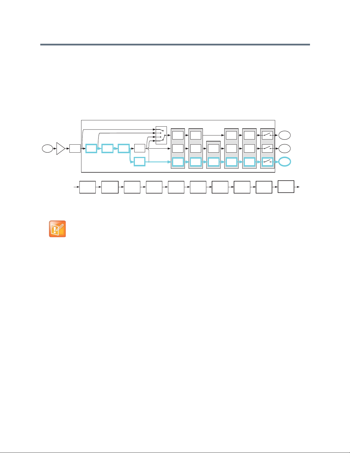
Mic or Line
Input
Input to
Matrix
Input to
Matrix
Parametric
Equalization
A/D
Converter
Analog
Gain
Acoustic Echo
Cancellation
Noise
Cancellation
Automatic
Gain Control
Automixer
AGC Dynamics Fader Delay
Fader
Automixer
Automixer
Delay
Automatic
Gain Control
Non Linear
Processing
Feedback
Cancellation
Dynamics
Processor
Dynamics
Processor
Fader
Input to
Matrix
Automatic
Gain Control
Fader Delay
Dynamics
Processor
Delay
Mute
Recording/
Ungated
Conferencing
Sound
Reinforcement
C-Series Sound Reinforcement Input Processing
Parametric
Equalization
Acoustic Echo
Cancellation
Noise
Cancellation
Automatic
Gain Control
Fader
Automixer
Delay
Feedback
Cancellation
Dynamics
Processor
Mute
The automatic gain control on the sound reinfor cemen t path is d ifferent from the automatic gain control on
the conferencing version of the signal because the sound reinforcement automatic gain control does not
add gain to the signal. In other words, the sound reinforcement AGC only reduces the gain of the input
signal. This restriction on the sound reinforcement AGC is to prevent the automatic gain control on the
sound reinforcement path from increasing the microphone gain and consequently reducing the potential
acoustic gain before the onset of feedback.
SoundStructure C-Series Sound Reinforcement Processing Signal Path
Note: No Gain Control Added to Signal
The automatic gain control on the sound reinforcement processing path does not
add gain to the signal, it only reduces the gain of the signal.
Processing Recording/Ungated Version
The recording version of the processed input signal is specifically designed to not include the gai n sharing
or gated style of automatic microphone mixing processing. The recording/ungated version of the input
channel is typically used for recording applications or in any application where an un-automixed version of
the input signal is required.
For additional flexibility in audio applications, there are four versions of the recording/ungated signal that
you can select through the four-input router, as shown in the above processing figures. The selection of
which type of recording/ungated signal to choose is performed on an input by input basis within the
SoundStructure Studio software, as described in Customizing SoundStructure Designs.
The four recording/ ungated versions are listed below:
● Bypass
● Line Input
● Conferencing
● Sound reinforcement
Processing Recording/Ungated–Bypass
The recording/ungated-bypass has no input processing other than a fader gain control, input delay, and
input mute. This version bypasses the automatic gain control and dynamics processing, as shown in the
Polycom, Inc. 26
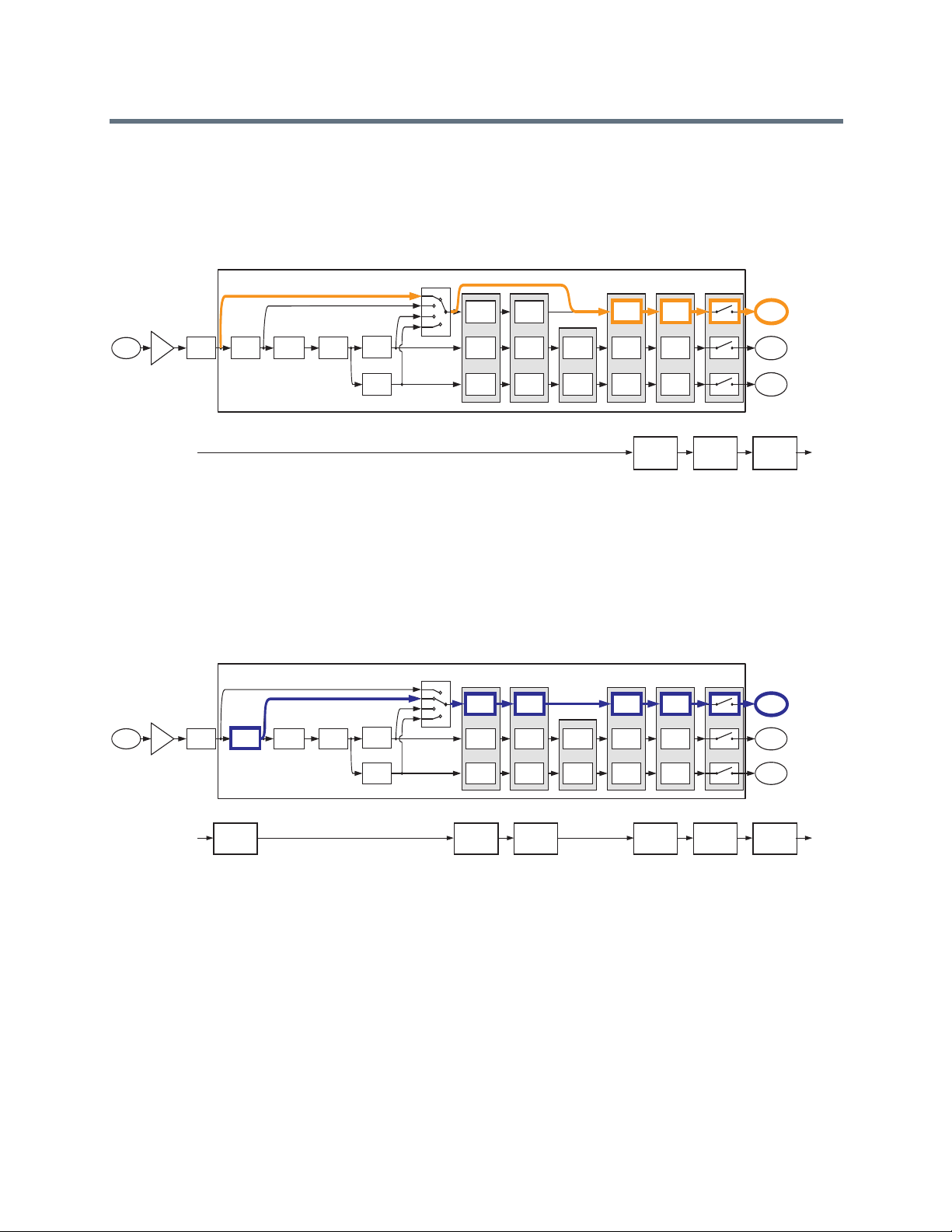
Mic or Line
Input
Input to
Matrix
Input to
Matrix
Parametric
Equalization
A/D
Converter
Analog
Gain
Acoustic Echo
Cancellation
Noise
Cancellation
Automatic
Gain Control
Automixer
AGC Dynamics Fader Delay
Fader
Automixer
Automixer
Delay
Automatic
Gain Control
Non Linear
Processing
Feedback
Cancellation
Dynamics
Processor
Dynamics
Processor
Fader
Input to
Matrix
Automatic
Gain Control
Fader Delay
Dynamics
Processor
Delay
Mute
Recording/
Ungated
Conferencing
Sound
Reinforcement
UNGATED - Bypass
Fader Delay
Mute
Mic or Line
Input
Input to
Matrix
Input to
Matrix
Parametric
Equalization
A/D
Converter
Analog
Gain
Acoustic Echo
Cancellation
Noise
Cancellation
Automatic
Gain Control
Automixer
AGC Dynamics Fader Delay
Fader
Automixer
Automixer
Delay
Automatic
Gain Control
Non Linear
Processing
Feedback
Cancellation
Dynamics
Processor
Dynamics
Processor
Fader
Input to
Matrix
Automatic
Gain Control
Fader Delay
Dynamics
Processor
Delay
Mute
Recording/
Ungated
Conferencing
Sound
Reinforcement
UNGATED - Line Input Processing
Parametric
Equalization
Automatic
Gain Control
Fader Delay
Dynamics
Processor
Mute
following figure. You can use the bypass version for minimal audio processing on an input signal. This
version of the signal has no acoustic echo cancellation processing and con sequently includes any acoustic
echo signal that may be present at the microphones.
SoundStructure C-Series Recording/Ungated–Bypass Path
Processing Recording/Ungated–Line Input
The recording/ungated line input includes equalization, automatic gain control, and the dynamics
processing as well as fader gain control, input delay, and input mute, as shown in the following figure. This
processing path is typically used by line input signals such as program audio.
SoundStructure C-Series Recording Ungated–Line Input Path
Processing Recording/Ungated–Conferencing
The recording/ungated conferencing processed input includes acoustic echo and noise cancellation, as
shown in the following figure. This path is used for the recording of conference microphones as it includes
all the acoustic echo cancellation but not the automatic microphone mixer processing.
Polycom, Inc. 27

Mic or Line
Input
Input to
Matrix
Input to
Matrix
Parametric
Equalization
A/D
Converter
Analog
Gain
Acoustic Echo
Cancellation
Noise
Cancellation
Automatic
Gain Control
Automixer
AGC Dynamics Fader Delay
Fader
Automixer
Automixer
Delay
Automatic
Gain Control
Non Linear
Processing
Feedback
Cancellation
Dynamics
Processor
Dynamics
Processor
Fader
Input to
Matrix
Automatic
Gain Control
Fader Delay
Dynamics
Processor
Delay
Mute
Recording/
Ungated
Conferencing
Sound
Reinforcement
UNGATED - Conferencing Processing
Parametric
Equalization
Acoustic Echo
Cancellation
Noise
Cancellation
Automatic
Gain Control
Fader Delay
Non Linear
Processing
Dynamics
Processor
Mute
Mic or Line
Input
Input to
Matrix
Input to
Matrix
Parametric
Equalization
A/D
Converter
Analog
Gain
Acoustic Echo
Cancellation
Noise
Cancellation
Automatic
Gain Control
Automixer
AGC Dynamics Fader Delay
Fader
Automixer
Automixer
Delay
Automatic
Gain Control
Non Linear
Processing
Feedback
Cancellation
Dynamics
Processor
Dynamics
Processor
Fader
Input to
Matrix
Automatic
Gain Control
Fader Delay
Dynamics
Processor
Delay
Mute
Recording/
Ungated
Conferencing
Sound
Reinforcement
UNGATED - Sound Reinforcement Processing
Parametric
Equalization
Acoustic Echo
Cancellation
Noise
Cancellation
Automatic
Gain Control
Fader Delay
Feedback
Cancellation
Dynamics
Processor
Mute
SoundStructure C-Series Recording Ungated–Conferencing Path
Processing Recording/Ungated–Sound Reinforcement
Finally, the sound reinforcement recording/ungated input includes the echo and noise cancellation and
optional feedback elimination processing, as shown in the following figure.
SoundStructure C-Series Recording Ungated–Sound Reinforcement Path
All versions of the recording/ungated input signal pr ocessing can be used simultaneously in th e matrix. The
conferencing version is typically used to send to remote participants, the sound reinforcement version is
typically used to send to the local loudspeaker system, and the recording version is typically used for
archiving the conference audio content.
Creating C-Series Matrix Crosspoints
The audio matrix is used to create different mixes of input signals and submix signals are sent to output
signals and submix signals. Matrix crosspoints gain values are shown in dB where 0 dB means a signal
value is unchanged. For example, a crosspoint value of -6 dB lowers the signal gain by 6 dB before it is
summed with other signals. You can adjust the matrix crosspoint gain in 0.1 dB steps between -100 and +20
dB, and you can also completely mute the matrix crosspoint. In addition, you can also negate and invert the
matrix crosspoint so that the crosspoint arithmetic creates a subtraction rather than an addition. The
inversion technique is effective in difficult room reinforcement environments by creating phase differences
in alternating zones to add more gain before feedback.
Polycom, Inc. 28

Outputs
Ungated/Recording
Conferencing
Sound Reinforcement
Ungated/Recording
Conferencing
Sound Reinforcement
Ungated/Recording
Conferencing
Sound Reinforcement
Ungated/Recording
Conferencing
Sound Reinforcement
Inputs
Crosspoint background indicates
version of input processing
White - Ungated/Recording
Blue - Conferencing (C-series),
Noise cancelled (SR-series)
Light Blue - Sound Reinforcement
Value of crosspoint is the gain in dB
Arc indicates L/R balance or pan
No arc indicates centered balance/pan
Underscore indicates Inverted polarity
Bold text Indicates signal is unmuted
Matrix crosspoints associated with stereo channels have a balance or pan to control mapping mono to
stereo channels, stereo to mono channels, and stereo to stereo channels.
The three different versions of the input processing - the ungated, conferencing, and sound reinforcement
- are selected at the matrix crosspoint. The SoundStructu re Studio software allows the user to select which
version of the input signal processing at the matrix crosspoint. As shown in Creating Designs with
SoundStructure Studio, the different versions of the input processing are represented with different
background colors in the matrix crosspoint.
The following figure highlights how to interpret the matrix crosspoints in the matrix.
SoundStructure C-Series Matrix Crosspoints
Understanding C-Series Output processing
As shown in the following table and figure, each output signal from the matrix can be processed with
dynamics processing, either 10-band parametric or 10-, 15-, or 31-band graphic equalization, a fader, and
output delay up to 1000 milliseconds.
SoundStructure C-Series Output Signal Processing
Output Processing
1st or 2nd order high shelf and low shelf filters
1st or 2nd order high shelf and low shelf filters
10-bands of parametric or 31-band graphic equalizer
Dynamics processing: gate, expander, compressor, limiter, peak limiter
Signal fader gain: +20 to -100 dB
Signal delay: up to 1000 msec
Polycom, Inc. 29
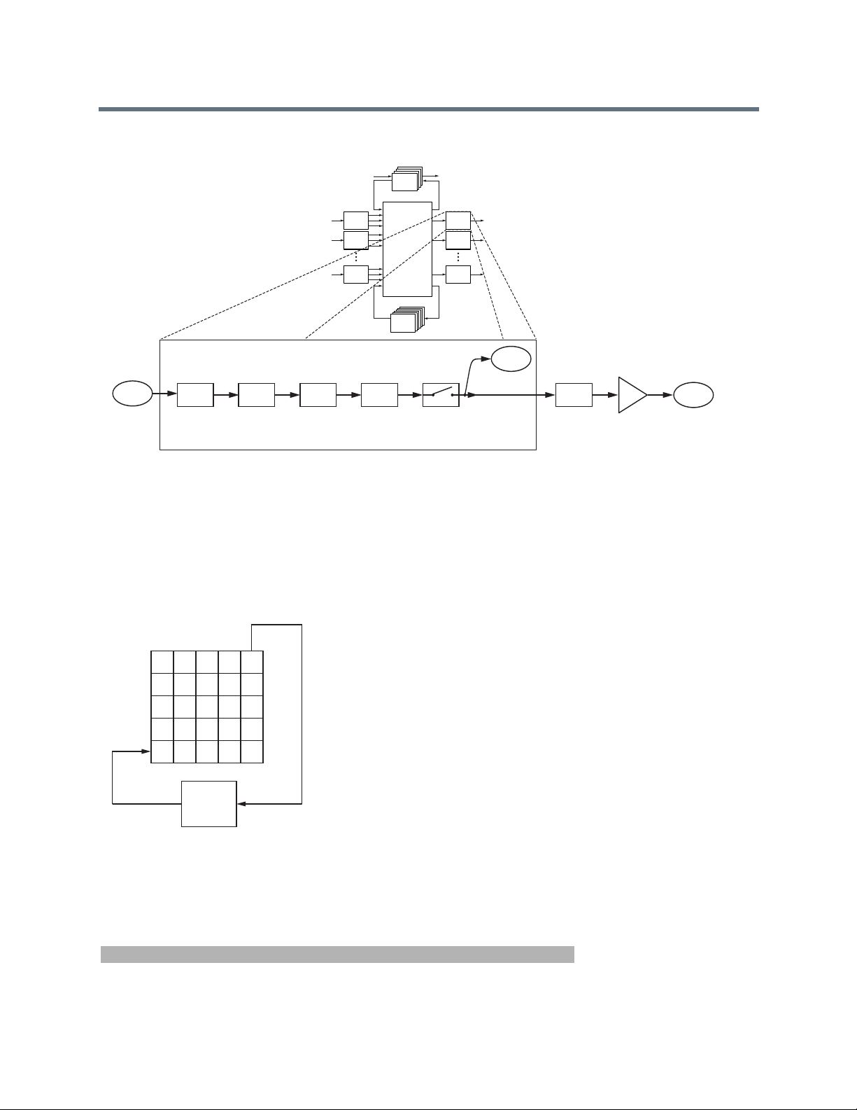
Submix
Processing
Matrix
Output
SubMix
Signal
Matrix
Input
SoundStructure C-Series Output Signal Processing
Processing
Processing
Processing
Telco
Telco
Telco
Processing
Telco
Output from
Matrix
Output Processing
Dynamics
Processing
Parametric
or Graphic
Equalization
Input
1
Processing
Input
2
Processing
Input
N
Processing
Fader Delay
Matrix
SubMix
Submix
Processing
Processsing
Mute
Output
Processing
Output
Processing
Output
Processing
1
2
N
AEC
Reference
D/A
Converter
Analog
Gain
Output
Signal
Processing C-Series Submixes
Submixes are outputs from the matrix that can be routed directly back to th e input of the matrix as shown in
the following figure.
SoundStructure C-Series Submix Signal Matrix
As an output of the matrix, any combination of input signals can be mixed together to create the output
submix signal. This output signal can be processed with the submix proce ssing and the processed signal is
available as an input to the matrix. Microphones, remote audio sources, or other signals are typically sent
to a submix channel and the resulting submix signal is used as a single input in the matrix.
SoundStructure C-Series Submix Processing
Submix Processing
Up to 8th order highpass and lowpass filters
Polycom, Inc. 30

SoundStructure C-Series Submix Processing
1st or 2nd order high shelf and low shelf filters
10-bands of parametric equalization
Dynamics processing: gate, expander, compressor, limiter, peak limiter
Signal fader gain: +20 to -100 dB
Signal delay: up to 1000 msec
As shown in the following figure, each submix signal from the matrix is processed with dynamics processing,
parametric equalization, a fader, and up to 1000 milliseconds of delay. Each SoundStructure device has as
many submixes as there are inputs.
SoundStructure C-Series Submix Processing
Telco
Telco
Telco
Processing
Telco
Processing
Processing
Processing
1
2
N
Input
Processing
Input
Processing
Input
Processing
Matrix
SubMix
Submix
Proce ssing
Processsing
Output
Processing
Output
Processing
Output
Processing
1
2
N
Submix Processing
Submix Input
from Matrix
Dynamics
Processing
Parametric
Equalization
Fader Delay
Mute
Submix output
to Matrix
Understanding C-Series Acoustic Echo Canceller References
In conferencing applications, an acoustic echo canceller (AEC) removes the remote site's audio that is
played in the local room and prevents the audio from being picked up by the local microphones and sent
Polycom, Inc. 31

AmpA
AEC reference for remote roomAEC reference for local room
back to the remote participants. The AEC
Local Room
in the following figure removes the acoustic echo of the
remote talker so the audio is not sent back to the remote talker.
SoundStructure C-Series Acoustic Echo Cancellation Process
Local Room
mp
Local Room
AEC
LocalTalker Remote Talker
Remote Room
AEC
Remote Room
Acoustic echo cancellation processing is only required on the inputs that have micr ophone audio connected
which can potentially hear both the local talkers’ speech and the acoustic echo of the remote talkers’
speech.
In order for the local acoustic echo canceller to cancel the acoustic echo of the remote participants, it must
have an echo canceller reference defined. The echo canceller reference includes all the signals from the
remote site that needs echo canceling. In the abo ve figure, the AEC reference for both the local and remote
rooms includes the audio that is played out the loudspeaker. See Appendix C: Design in g Audio
Conferencing Systems for additional information on audio conferencing systems and acoustic echo
cancellation.
Within SoundStructure devices, the acoustic echo canceller on each input can have either one or two AEC
references specified per input signal. For traditional monaural audio or video conferencing applications, only
one acoustic echo canceller reference is used which is typically sent to the single loudspeaker zone. See
the Creating an Eight Microphones, Video, and Telephony Application Conferencing System in Creating
Advanced Applications for an example.
Applications that have two independent audio sources played into the room such as stereo audio from a
stereo video codec require two mono AEC references, or one stereo AEC refer ence. See Creating an Eight
Microphones and Stereo Video Conferencing System in Creating Advanced Applications.
You can create an acoustic echo canceller reference from any output signal or any submix signal. For a
SoundStructure C16 device, this means that there are 32 possible echo canceller references (16 outputs +
16 submixes) that you can define and select.
Understanding SoundStructure SR-Series Products
The SoundStructure SR12 has a similar architecture to the SoundStructure C-series. While the
SoundStructure SR12 does not include acoustic echo cancellation processing, the SR12 do es include noise
cancellation, automatic microphone mixing, matrix mixing, equalization , fee dback elimination, dynamics
processing, delay, and submix processing.
Polycom, Inc. 32

Telco
Video Codec
Amplifier
SoundStructure
C8
SoundStructure
SR12
Microphones
Telephony
Loudspeakers
Video
Local
Audio
Playback
Network
PSTN
Network
Playback/Record
Favorite Content
Playback/Record
Favorite Content
Amplifier
Loudspeakers
Local
Audio
Playback
SR-Series
12:00 am
VHS
The SoundStructure SR12 is designed for both the non-conferencing applications where local audio is
played into the local room or distributed throughout a facility and for conferencing applications to provide
additional line input and output signals when linked to a C-series product. Applications for the
SoundStructure SR12 include live sound, presentation audio, sound rein forcement, and broadcasting. The
following figure shows an example of using the SoundStructure SR12 to provide additional line level inputs
and outputs to a SoundStructure C8 conferencing product.
SoundStructure SR12 Providing Line Level Inputs and Outputs for a SoundStructure C8
The SoundStructure SR12 can not be used to add additional conferencing microphones to a C series
product because there is no acoustic echo cancellation processing on the SoundStructure SR12 inputs. The
following figure shows an installation that does not work because the microphones that are connected to
the SoundStructure SR12 are not echo ca nceled. If you need more conferencing m icrophones than can be
Polycom, Inc. 33

Telco
Video Codec
Amplifier
SoundStructure
C8
SoundStructure
SR12
Microphones
Telephony
Loudspeakers
Video
Local
Audio
Playback
Network
PSTN
Network
Amplifier
Loudspeakers
Local
Audio
Playback
SR-Series
used with a particular SoundStructure C-series device, you can use either the next lar gest C-series device
or additional C-series devices to support the number of microphones required.
Installation Not Supported with SoundStructure SR12
Y o u can use the C-series and SR-series produ cts together and link the devices to fo rm larger systems that
can support up to eight SoundStructure devices, 128 inputs, 128 outputs, and eight plug-in daug hter cards.
For information on how to rack mount and terminate cables to the SoundStructure devices, refer to the
SoundStructure Hardware Installation Guide.
Understanding SR-Series Input Processing
The input processing on the SoundStructure SR-series devices is designed to make it easy to create
commercial sound and sound reinforcement solutions. Each audio input on a SoundStructure SR-series
device includes the signal processing path shown in the following table.
SoundStructure SR-Series Signal Input Processing Path
SR-Series Input Processing
Up to 8th order highpass and lowpass
1st or 2nd order high shelf and low shelf
10-bands of parametric equalization
Automatic gain control: +15 to -15dB
Dynamics processing: gate, expander, compressor, limiter, peak limiter
Polycom, Inc. 34

Mic or Line
Input
Input to
Matrix
Input to
Matrix
Parametric
Equalization
A/D
Converter
Analog
Gain
Noise
Cancellation
Automatic
Gain Control
Automixer
AGC Dynamics Fader Delay
Fader
Automixer
Automixer
Delay
Automatic
Gain Control
Feedback
Cancellation
Dynamics
Processor
Dynamics
Processor
Fader
Input to
Matrix
Automatic
Gain Control
Fader Delay
Dynamics
Processor
Delay
Mute
Recording/
Ungated
Noise Cancelled
Sound
Reinforcement
SoundStructure SR-Series Signal Input Processing Path
Feedback Eliminator: 10 adaptive filters
Noise cancellation: 0-20dB noise reduction
Automixer: gain sharing or gated mixer
Signal fader gain: +20 to -100 dB
Signal delay: up to 1000 msec
The processing for each input is shown in the following figure from analog input signal to the three ver sions
of input processing that lead to the matrix.
SoundStructure SR-Series Input Processing
Telco
Telco
Telco
Processing
Telco
Processing
Processing
Processing
Input
1
Processing
Input
2
Processing
Input
N
Processing
Matrix
SubMix
Submix
Processing
Processsing
Output
Processing
Output
Processing
Output
Processing
1
2
N
Each analog input signal has an analog gain stage that is used to adjust the gain of the input signal to the
SoundStructure's nominal signal level of 0 dBu. The analog gain stage can provide from -20 to 64 dB of
Polycom, Inc. 35

Mic or Line
Input
Parametric
Equalization
A/D
Converter
Analog
Gain
Noise
Cancellation
Feedback
Cancellation
SR-Series Input Processing
Rou
analog gain in 0.5 dB increments. There is also an option to enable 48 V phantom power on each input.
Finally, the analog input signal is digitized and ready for processing.
SoundStructure SR-Series Input Processing
Mic or Line
Input
SR-Series Input Processing
A/D
Parametric
Analog
Converter
Gain
Equalization
Noise
Cancellation
Feedback
Cancellation
AGC Dynamics Fader Delay
Automatic
Dynamics
Gain Control
Automatic
Gain Control
Automatic
Gain Control
Processor
Dynamics
Processor
Dynamics
Processor
Router
Automixer
Automixer
Automixer
Fader Delay
Fader
Fader
Input to
Matrix
Input to
Delay
Matrix
Input to
Delay
Matrix
Continuing through the signal path as shown in the next figure, the input signal processing continues
through the automatic gain control (AGC), dynamics processing, an automixer, an audio fader, and finally
through the input delay.
Each analog input signal is processed to generate th ree different versions of the processed input signal that
can be used simultaneously in the matrix. The following are the three versions of processed input signal:
● Noise canceled
● Sound reinforcement
● Recording/ungated
The AGC, dynamics processor, and input fader are linked together on all three audio paths and apply the
same gain to the signal paths based on an analysis of the signal earlier in the signal path.
Polycom, Inc. 36

Input to
Matrix
Input to
Matrix
Automatic
Gain Control
Automixer
AGC Dynamics Fader Delay
Fader
Automixer
Automixer
Delay
Automatic
Gain Control
Dynamics
Processor
Dynamics
Processor
Fader
Input to
Matrix
Automatic
Gain Control
Fader Delay
Dynamics
Processor
Delay
Mute
Router
Recording/
Ungated
Noise Cancelled
Sound
Reinforcement
The automixer processing is only applied to the noise canceled and sound reinforcement signal paths to
ensure that there is an un-automixed version of the input signal available for recording/ungated applications.
SoundStructure SR-Series Processed Input Signals
SR-Series Input Processing
A/D
Parametric
Mic or Line
Analog
Converter
Input
Gain
Noise
Equalization
Cancellation
Feedback
Cancellation
AGC Dynamics Fader Delay
Automatic
Dynamics
Gain Control
Router
Processor
Dynamics
Automatic
Processor
Gain Control
Automatic
Dynamics
Gain Control
Processor
Fader Delay
Automixer
Fader
Automixer
Fader
Automixer
Mute
Input to
Recording/
Matrix
Ungated
Delay
Delay
Input to
Noise Cancelled
Matrix
Sound
Input to
Matrix
Reinforcement
Note: Analog Input Signal Processing
Each analog input signal is processed to create three processed versions that are
used in different ways in the matrix.
These three different versions of the input signal mean that, at the same time, an output signal to the
loudspeakers can use the sound reinforcement processed version of an inp ut signal, another output signal
can use the noise canceled version without feedback processing, and a different output signal can use the
recording version of the input signal. The decision of which of these three processed ver sions to use is made
at each matrix crosspoint as described in Creating SR-Series Matrix Crosspoints.
Processing Noise Canceled
The conferencing version is processed with input equalization, noise cancellation, automatic gain control,
dynamics processing, automixer, fader, delay , and input mute. The noise canceled signal path is highlighted
in the following figure and the block diagram of this processing is also shown. Th is is the path that is typically
used to send a noise reduced version of the microphone audio to paging zones that are not acoustically
Polycom, Inc. 37

Mic or Line
Input
Input to
Matrix
Input to
Matrix
Parametric
Equalization
A/D
Converter
Analog
Gain
Noise
Cancellation
Automatic
Gain Control
Automixer
AGC Dynamics Fader Delay
Fader
Automixer
Automixer
Delay
Automatic
Gain Control
Feedback
Cancellation
Dynamics
Processor
Dynamics
Processor
Fader
Input to
Matrix
Automatic
Gain Control
Fader Delay
Dynamics
Processor
Delay
Mute
Recording/
Ungated
Noise Cancelled
Sound
Reinforcement
SR-Series Noise Cancellation Input Processing
Parametric
Equalization
Noise
Cancellation
Automatic
Gain Control
Fader
Automixer
Delay
Dynamics
Processor
Mute
Mic or Line
Input
Input to
Matrix
Input to
Matrix
Parametric
Equalization
A/D
Converter
Analog
Gain
Noise
Cancellation
Automatic
Gain Control
Automixer
AGC Dynamics Fader Delay
Fader
Automixer
Automixer
Delay
Automatic
Gain Control
Feedback
Cancellation
Dynamics
Processor
Dynamics
Processor
Fader
Input to
Matrix
Automatic
Gain Control
Fader Delay
Dynamics
Processor
Delay
Mute
Recording/
Ungated
Noise Cancelled
Sound
Reinforcement
Parametric
Equalization
Noise
Cancellation
Automatic
Gain Control
Feedback
Cancellation
Fader
Automixer
Delay
Dynamics
Processor
Mute
coupled to the microphone. This is the default processing for microphone inputs when the automixed
version of the signal is selected.
SoundStructure SR-Series Noise Cancellation Processing
Processing Sound Reinforcement
The sound reinforcement version is processed with the parametric equalization , noise cancellation, optional
feedback elimination processing, automatic gain control, dynamics processing, automixer , fader , delay, and
input mute. This is the path that is typically used for sending local audio to loudspeakers in the room for
sound reinforcement.
The automatic gain control on the sound reinfor cemen t path is d ifferent from the automatic gain control on
the noise canceled version of the signal in that the sound reinfor cement automatic gain control does not add
gain to the signal. In other words, the sound reinforcement AGC only reduces the gain of the signal and
does not add gain to the signal. This restriction on the sound reinforcement AGC prevents the automatic
gain control from reducing the available poten ti al acoustic gain before the onset of feedback.
SoundStructure SR-Series Sound Reinforcement Input Processing
Processing Recording/Ungated Version
The recording version of the processed input signal is specifically designed to not include any gain sharing
or gated-style of automatic microphone mixing processing. The recording/ungated version of the input is
used for recording applications or in any application where an un-automixed version of the input signal is
required.
For additional flexibility in audio applications, there are four different versions of the recording/ungated
signal that can be selected through the four-input router shown in the previous processing figures. This
Polycom, Inc. 38

selection of which type of recording/ungated signal to choose is performed on an input by input basis within
the SoundStructure Studio software as described in Customizing SoundStructure Designs.
The following are four ungated versions of the processed input signal:
● Bypass
● Line input
● Noise cancellation
● Sound reinforcement
Processing Recording/Ungated–Bypass
The recording/ungated bypass version has no input processing other than a fa der gain control, input delay,
and input mute. This version bypasses the automatic gain control and dynamics processing, as shown in
the following figure. This version can be used when it is important to have minimal audio processin g on an
input signal.
Polycom, Inc. 39

Mic or Line
Input
Input to
Matrix
Input to
Matrix
Parametric
Equalization
A/D
Converter
Analog
Gain
Noise
Cancellation
Automatic
Gain Control
Automixer
AGC Dynamics Fader Delay
Fader
Automixer
Automixer
Delay
Automatic
Gain Control
Feedback
Cancellation
Dynamics
Processor
Dynamics
Processor
Fader
Input to
Matrix
Automatic
Gain Control
Fader Delay
Dynamics
Processor
Delay
Mute
Recording/
Ungated
Noise Cancelled
Sound
Reinforcement
UNGATED - Bypass
Fader Delay
Mute
Mic or Line
Input
Input to
Matrix
Input to
Matrix
Parametric
Equalization
A/D
Converter
Analog
Gain
Noise
Cancellation
Automatic
Gain Control
Automixer
AGC Dynamics Fader Delay
Fader
Automixer
Automixer
Delay
Automatic
Gain Control
Feedback
Cancellation
Dynamics
Processor
Dynamics
Processor
Fader
Input to
Matrix
Automatic
Gain Control
Fader Delay
Dynamics
Processor
Delay
Mute
Recording/
Ungated
Noise Cancelled
Sound
Reinforcement
UNGATED - Line Input Processing
Parametric
Equalization
Automatic
Gain Control
Fader Delay
Dynamics
Processor
Mute
Mic or Line
Input
Input to
Matrix
Input to
Matrix
Parametric
Equalization
A/D
Converter
Analog
Gain
Noise
Cancellation
Automatic
Gain Control
Automixer
AGC Dynamics Fader Delay
Fader
Automixer
Automixer
Delay
Automatic
Gain Control
Feedback
Cancellation
Dynamics
Processor
Dynamics
Processor
Fader
Input to
Matrix
Automatic
Gain Control
Fader Delay
Dynamics
Processor
Delay
Mute
Recording/
Ungated
Noise Cancelled
Sound
Reinforcement
UNGATED - Noise Cancellation Processing
Parametric
Equalization
Noise
Cancellation
Automatic
Gain Control
Fader Delay
Dynamics
Processor
Mute
SoundStructure SR-Series Bypass Signal Processing
Processing Recording/Ungated–Line Input
The recording line input version includes equalization, automatic gain control, and the dynamics processing
as well as fader gain control, input delay, and input mute, as shown in the next figure. This processing path
is typically used by line input signals such as program audio, and hence the name line input path.
SoundStructure SR-Series Line Input Signal Processing
Processing Recording/Ungated - Noise Cancellation
The noise canceled recording input includes the noise cancellation as shown in the next figu re. This path is
typically used for recording of microphone audio as it includes all the noise cancellation but not the
automatic microphone mixer processing.
SoundStructure SR-Series Noise Cancellation Signal Processing
Processing Recording/Ungated - Sound Reinforcement
Polycom, Inc. 40

Mic or Line
Input
Input to
Matrix
Input to
Matrix
Parametric
Equalization
A/D
Converter
Analog
Gain
Noise
Cancellation
Automatic
Gain Control
Automixer
AGC Dynamics Fader Delay
Fader
Automixer
Automixer
Delay
Automatic
Gain Control
Feedback
Cancellation
Dynamics
Processor
Dynamics
Processor
Fader
Input to
Matrix
Automatic
Gain Control
Fader Delay
Dynamics
Processor
Delay
Mute
Recording/
Ungated
Noise Cancelled
Sound
Reinforcement
UNGATED - Sound Reinforcement Processing
Parametric
Equalization
Noise
Cancellation
Automatic
Gain Control
Feedback
Cancellation
Fader Delay
Dynamics
Processor
Mute
Finally, the sound reinforcement recording input includes the noise canc ellation and optional feedback
elimination processing as shown in the following figure.
Creating SR-Series Matrix Crosspoints
The audio matrix is used to create different mixes of input signals and submix signals to be sent to output
signals and submix signals. Matrix crosspoints gain valu es are show n in dB wh er e 0 dB me a ns th at the
signal level is unchanged. Matrix crosspoint gains can be adjusted in 0.1 dB steps between -100 and +20
dB and may also be completely muted. In addition, the matrix crosspoint can also be negated/inverted so
that the crosspoint arithmetic creates a subtraction instead of an addition.
Matrix crosspoints associated with stereo virtual channels have a balance or pan to control mapping mono
to stereo virtual channels, stereo to mono virtual channels, and stereo to stereo virtual channels.
The different versions of the input processing are selected at the matrix crosspoint. The user interface
provides an option for selecting the different versions of the input pr ocessing including the noise cancel ed,
sound reinforcement, and ungated/recording version. As shown in Creating Designs with SoundStructure
Studio, different versions of the input processing are represented with different background colors at the
matrix crosspoint. The SoundStructure Studio software a llows the user to select wh ich version of th e input
signal processing at the matrix crosspoint.
Polycom, Inc. 41

The next figure shows how to interpret the matrix crosspoint view.
SoundStructure SR-Series Matrix Crosspoint
Understanding SR-Series Output Processing
The output processing for the SR-series of products is iden tical to the processing for the output processing
in the C-series and is shown in the table and following figure.
SoundStructure SR-Series Output Processing
Output Processing
1st or 2nd order high shelf and low shelf filters
10-bands of parametric or 31-band graphic equalizer
Dynamics processing: gate, expander, compressor, limiter, peak limiter
Signal fader gain: +20 to -100 dB
Signal delay: up to 1000 msec
Polycom, Inc. 42

SoundStructure SR-Series Output Processing
Processing
Telco
Telco
Telco
Processing
Telco
Processing
Processing
Input
1
Processing
Input
2
Processing
Input
N
Processing
Matrix
SubMix
Submix
Processing
Processsing
Output
Processing
Output
Processing
Output
Processing
1
2
N
SR-Series Output Processing
Output from
Matrix
Dynamics
Processing
Parametric
or Graphic
Equalization
Fader Delay Mute
D/A
Converter
Analog
Gain
Output
Signal
Processing SR-Series Submix
The submix processing for the SR-series of products is identical to the processing for the submix processing
in the C-series and shown in the following table and figure.
SoundStructure SR-Series Submix Processing
Submix Processing
Up to 8th order highpass and lowpass filters
1st or 2nd order high shelf and low shelf filters
10-bands of parametric equalization
Dynamics processing: gate, expander, compressor, limiter, peak limiter
Signal fader gain: +20 to -100 dB
Signal delay: up to 1000 msec
Polycom, Inc. 43

SoundStructure SR-Series Submix Processing
Telco
Telco
Telco
Processing
Telco
Processing
Processing
Processing
Input
1
Processing
Input
2
Processing
Input
N
Processing
Matrix
SubMix
Submix
Proce ssing
Processsing
Output
Processing
Output
Processing
Output
Processing
1
2
N
Submix Processing
Submix Input
from Matrix
Dynamics
Processing
Parametric
Equalization
Fader Delay
Mute
Submix output
to Matrix
Understanding Telephony Processing
Both the C-series and SR-series SoundStructure device s support optional plug-in cards. Cur rently there are
two telephony cards: TEL1, a single-PSTN line, and TEL2, a dual-PSTN line interface card in the form
factor, shown in the following figure.
SoundStructure Telephony Card
These cards are field-installable and are ordered separately from the SoundStructure C- or SR-series
devices. See the SoundStructure Hardware Installation Guide or the Hardware Installation Guide for the
TEL1 and TEL2 for additional information.
Polycom, Inc. 44

The SoundStructure telephony cards have been designed to meet various regional telephony requirements
through the selection of a country code from the u ser interface. For each telephony interface card, the signal
processing is listed in the following table and shown in the following figure.
The telephony transmit path includes dynamics processing, 10 bands of parametric equalization, up to 1000
milliseconds of delay , a fader with gain control from +20 to -100 dB, and a line echo canceller . There is also
a tone generator that is used to create DTMF digits and other call progress tones that may be sent to the
telephone line and also played into the local room.
SoundStructure SR-Series Telco Processing
Telco Processing
Line echo cancellation, 80-3300Hz, 32msec tail-time
Dynamics processing: gate, expander, compressor, limiter, peak limiter on telco
transmit and receive
Up to 8th order highpass and lowpass filters
1st or 2nd order high shelf and low shelf filters
10-bands of parametric equalization on telco transmit and receive
Call progress detection
Signal fader gain: +20 to -100 dB
Automatic gain control: +15 to -15dB on telco receive
Signal delay on telco transmit and receive: up to 1000 msec
Noise cancellation: 0-20dB noise reduction on telco receive
On the telephony receive path, the processing includes up to 20 dB of noise cancellation, automatic gain
control, dynamics processing, 10-band parametric equalization, fader, and audio delay. In addition there is
Polycom, Inc. 45
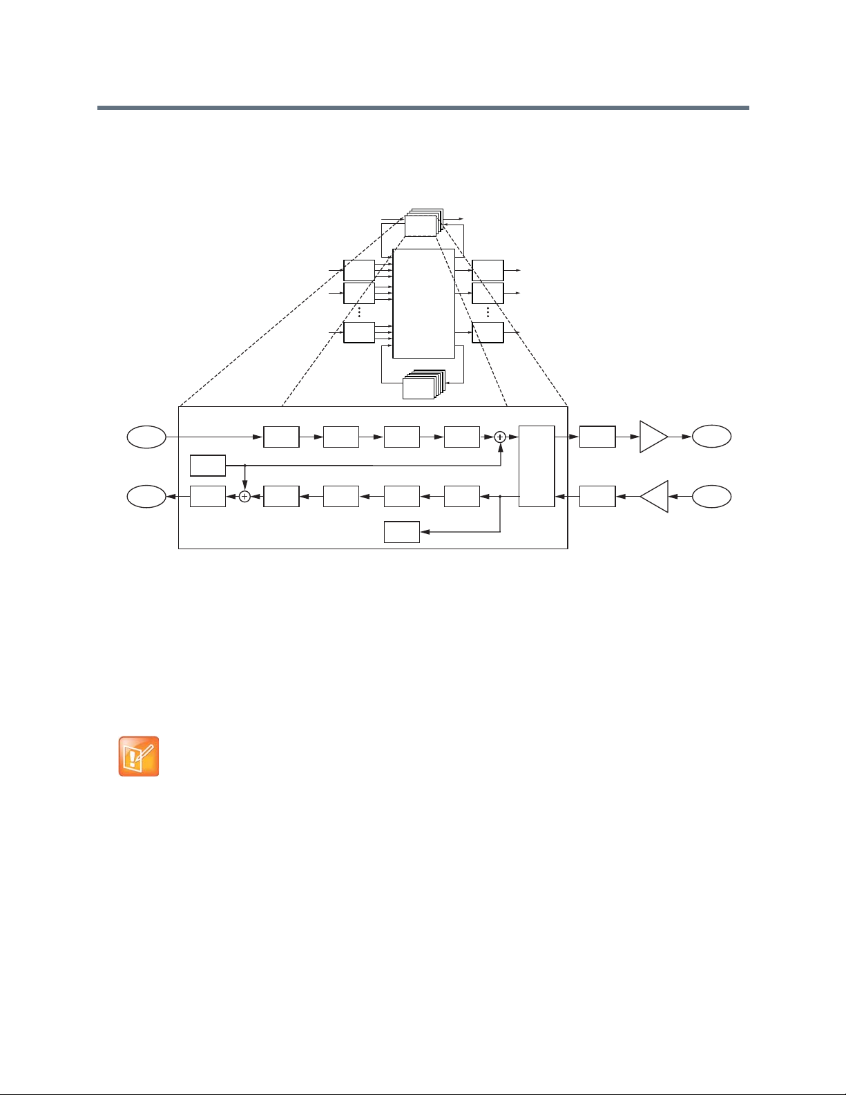
a call progress detector that analyzes the telephony input signal and reports if any call progress tones are
present. For example, if the telephony line is busy, the phone rings.
.SoundStructure SR-Series Telco Processing
Telco
Telco
Telco
Processing
Telco
Processing
Processing
Processing
Input
1
Processing
Input
2
Processing
Input
N
Processing
Matrix
SubMix
Submix
Processing
Processsing
Output
Processing
Output
Processing
Output
Processing
1
2
N
Telephony Processing
To Telco
from Matrix
From Telco
to Matrix
Tone
Generator
Fader
Dynamnics
Processing
Parametric
Equalization
Parametric
Equalization
Dynamics
Processing
Automatic
Gain Control
Call Progress
Detection
FaderDelay
Noise
Cancellation
Line Echo
Cancellation
D/A
Converter
A/D
Converter
Analog
Gain
Analog
Gain
Output to
PSTN Line
Input from
PSTN Line
Typically, the telephony cards are used in the C-series devices for audio conferencing applications. The
telephony cards are also supported on the SR-series allowing additional plug-in cards for multiple audio
conferencing telephone lines when C-series products are used with SR-series products. In some
commercial sound applications it is also useful to have telep hony access to either br oadcast or monitor the
audio in the system. Audio confer encing applications do not work with only SR-series devices because there
is no acoustic echo cancellation processing in the SR-series devices.
Note: Using Telephony Cards with the SR-Ser ies
The telephony cards should not be used with the SR-series of products for audio
conferencing applications (i.e., simultaneous two-way audio communication) unless
all the microphones in the system are connected to SoundStructure C-series
devices. The SR-series products do not have acoustic echo cancellation.
Polycom, Inc. 46

Introducing SoundStructure Design Concepts
Before creating designs for the SoundStructure devices, the concepts of physical channels, virtual
channels, and virtual channel groups are introduced. Th ese concepts form the foundation of SoundStructure
audio designs. In addition, the concepts of defining control virtual channels and control array virtual
channels from the logic input and output pins are introduced.
Understanding Device Inputs and Outputs
All audio devices have inputs and outputs that are used to connect to other devices such as microphones
and audio amplifiers. These inputs and outputs are labeled on the front or rear-panel (depending on the
product) with specific channel numbers, such as inputs 1, 2, 3, etc., and these label s refer to particular inputs
or outputs on the device. For instance, it is common to connect to input “1” or output “3 ” of an audio device.
This naming convention works well -- meaning that it provides a unique identifier, or name, for each input
and output -- as long as only a single device is used. As soon as a second device is added, input “1” no
longer uniquely identifies an input since there are now two input 1’s if a system is made from two devices.
Traditionally, to uniquely identify which input “1” is meant, there’s additional information required such as a
device identification name or number , requiring the user to specify input “1” on device 1 or input “1” on device
2 in order to uniquely identify that particular input or output. This device iden tification is also required wh en
sending commands to a collection of devices to ensure the command affects the proper input or outp ut
signal on the desired device.
As an example, consider what must happen when a control system is asked to mute input 1 on device 1.
The control system code needs to know how to access that particular input on that particular device. To
accommodate this approach, most audio systems have an API command structure that req uires specifying
the particular device, perhaps even a device type if th er e are mu ltiple type s of devices b eing u sed, a nd, of
course, the particular channel numbers to be affected by the command. This approach requires that the
designer manually configure the device identification for each device that is used and take extra care to
ensure that commands are referencing that exact input or output signal. If device identifica tion numbers are
changed or different inputs or outputs are used from one design to the next, this requires changing the
control system code programming and spending additional time debugging and testing the new code to
ensure the new device identifications and channel numbers are used properly. Every change is costly and
is error prone, and can often delay the completion of the installation.
SoundStructure products have taken a different, and simpler, approach to labeling the inp uts and outputs
when multiple devices are used together. SoundStructure products achieve this simplification through the
use of physical channels, virtual channels, and OBAM’s intelligent linking scheme. As shown in the
Understanding Physical Channels section, physical channels are the actual input and outputs numbers for
a single device and this numbering is extended sequentially when multiple devices are u sed. Understanding
Virtual Channels extends this concept by creating a layer over physical channels that allows the physical
channels to be referenced by a user defined label, such as “Podi um mic”, rather than a s a channel numbe r.
Polycom, Inc. 47

Input Physical Channel 3 Input Physical Channel 10
Output Physical Channel 6
1 2 3 4 5 6 7 8 9 10 11 12 13 14 15 16
1 2 3 4 5 6 7 8 9 10 11 12 13 14 15 16
OUTPUTS INPUTS
SoundStructure C16
TM
Understanding Physical Channels
SoundStructure defines physical channels as a channel that cor responds to the a ctu al inputs o r outputs o f
the SoundStructure system. Physical channels include the SoundStructure analog inputs, analog outputs,
submixes, the telephony interfaces, the conference link channels, and the logic input and output pins.
An example of physical channels is input 3, which corresponds to the physical analog input 3 on the
rear-panel of a SoundStructure device, input 10 (corresponds to analog input 10), and output 6, which
corresponds to the physical analog output 6 on a Soun dS tru ct ur e de vice , as show n in th e follo win g fig ure.
Example of Physical Input Channels
When designing with SoundStructure products, the analog inputs (such as microphones, or other audio
sources) and outputs from the system (such as audio sent to amplifiers) connect to SoundStructure’s
physical channels.
The physical input channels and the physical output ch annels are numbered from 1 to the maximum numbe r
of physical channels in a system. As described below, this approach is an enhancement of how traditional
audio signals are labeled and how their signals are uniquely referenced.
Numbering Physical Channel On A Single SoundStructure Device
As described previously, in single-device SoundStructure installations (for example using a single
SoundStructure C16), the physical channel numbering for the inputs and outputs corresponds to the
Polycom, Inc. 48

Input Physical Channels 1 - 16
Output Physical Channels 1 - 16
1 2 3 4 5 6 7 8 9 10 11 12 13 14 15 16
1 2 3 4 5 6 7 8 9 10 11 12 13 14 15 16
OUTPUTS INPUTS
SoundStructure C16
TM
numbering on the rear-panel of the device. For example, as shown in the following figure, physical input
channel 3 corresponds to input 3 on the SoundStructure C16 device.
Example of Corresponding Physical Channels on a Single SoundStructure Device
Numbering Physical Channel With Multiple SoundStructure Devices
When multiple SoundStructure devices are linked using One Big Audio Matrix (OBAM) to form a
multi-device SoundStructure system, instead of using a device identification number, the physical channel
numbering for both the inputs and the outputs ranges from 1 to the maximum number of inputs and outputs,
respectively, in the system. This is an extension of the single device setup where the physical channel
numbers for channels on the second device are the next numbers in the sequence of inputs from the first
device. For if there are two devices and the first device is a SoundStructure C16, the firs t input on the second
device becomes physical input 17. This continuation of the sequence of numbers is possible due to the
design of the OBAM Link interface.
OBAM Link is the method for connecting multiple devices together by connecting the OBAM Link cable from
one device to the next. The following figure shows the location of the OBAM connections and the OBAM
OUT and OBAM IN connections on the rear-panel of a SoundStructure device. To help verify when the
OBAM Link is connected properly, there are status LEDs near the outer edge of each connector that
illuminate when the devices are linked successfully.
Polycom, Inc. 49
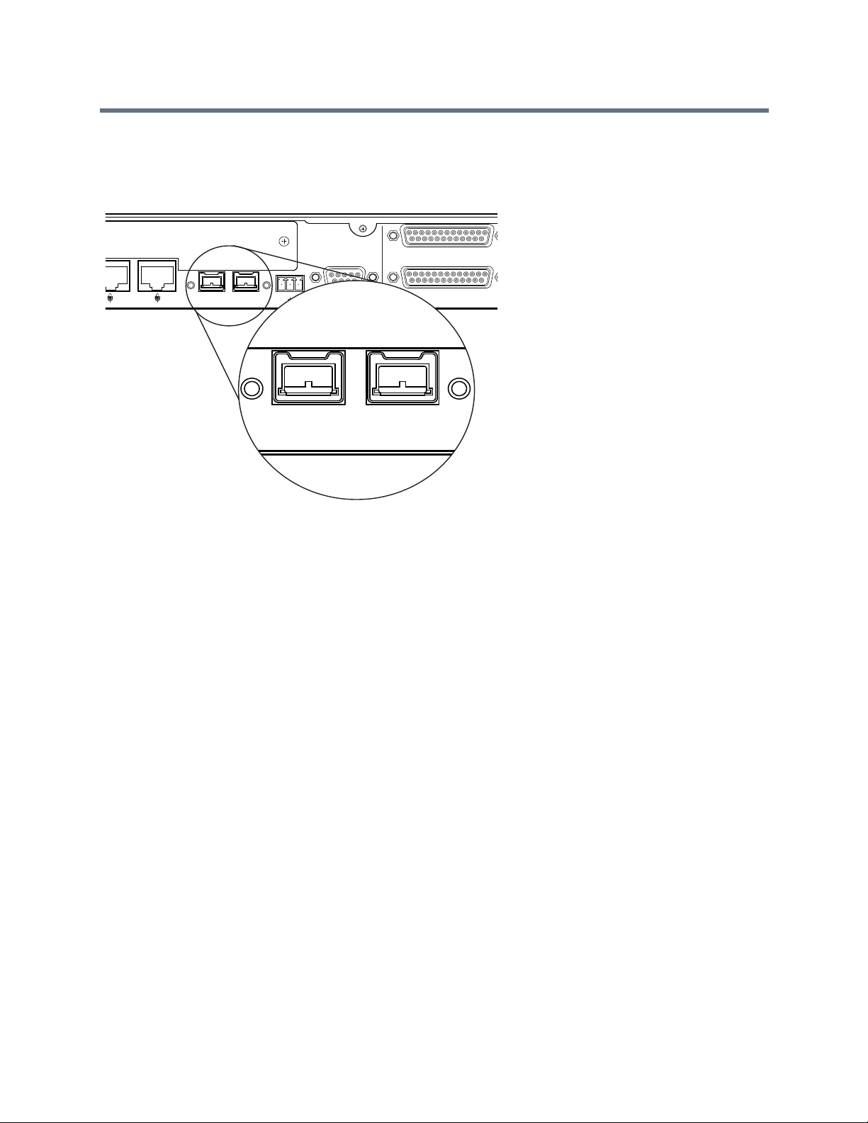
PIN 2: TXD
PIN 3: RXD
PIN 5: GROUND
PIN 7: CTS
PIN 8: RTS
C-LINK2
OBAM IR
RS-232
REMOTE CONTROL 2
IN OUT
12V
REMOTE CONTROL 1
OBAM I
IN OUT
The OBAM link is bidirectional - data flows in both an upstream and downstream direction meaning that the
bus does not need to be looped back to the first device.
OBAM Connections on a SoundStructure Device
When multiple devices are linked together via OBAM, the SoundStructure devices communicate to each
other, de termine which devices are linked and automatica lly generate internal d evice identifications. These
device identifications are sequential from the first device at device ID 1 through the latest device linked over
OBAM. Externally, there are no SoundStructure device identifications that must to be set or remembered.
The internal device identifications are not required by the user/designer and are not user settable.
As described previously, rather than referring to physical channels on different devices by using a device
identification number and a local physical input and output number, SoundStructure devices are designed
so that the physical channel numbering is sequential across multiple devices. This allows one to refer to
different channels on multiple devices solely by using a physical channel n umber that range s from 1 to the
maximum number of channels in the linked system. As shown next, how the devices are OBAM linked
determines the resulting numbering of the physical channels for the overall system.
To properly link multiple SoundStructure devices, connect the OBAM OUT port on the first device (typically
the top SoundStructure device in the equipment rack) to the OBAM IN port on the next SoundStructure
Polycom, Inc. 50
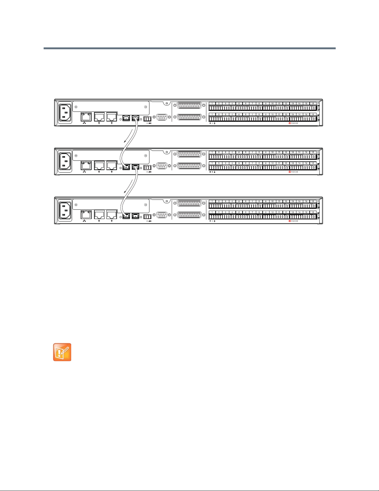
Connect
OBAM Out
to OBAM In
Connect
OBAM Out
to OBAM In
device and continue for additional devices. This connection strategy, shown in the following figures,
simplifies the sequential physical channel numbering as described next.
OBAM Connection Strategy for SoundStructure Devices
SoundStructure C16
SoundStructure C16
SoundStructure C16
OUTPUTS INPUTS
TM
OUTPUTS INPUTS
TM
OUTPUTS INPUTS
TM
PIN 2: TXD
PIN 3: RXD
PIN 5: GROUND
PIN 7: CTS
PIN 8: RTS
RS-232
12V
OBAM IR
LAN
C-LINK2
LAN
C-LINK2
LAN
C-LINK2
IN OUT
IN OUT
OBAM IR
IN OUT
OBAM IR
PIN 2: TXD
PIN 3: RXD
PIN 5: GROUND
PIN 7: CTS
PIN 8: RTS
RS-232
12V
PIN 2: TXD
PIN 3: RXD
PIN 5: GROUND
PIN 7: CTS
PIN 8: RTS
RS-232
12V
REMOTE CONTROL 1
REMOTE CONTROL 2
REMOTE CONTROL 1
REMOTE CONTROL 2
REMOTE CONTROL 1
REMOTE CONTROL 2
1 2 3 4 5 6 7 8 9 10 11 12 13 14 15 16
1 2 3 4 5 6 7 8 9 10 11 12 13 14 15 16
1 2 3 4 5 6 7 8 9 10 11 12 13 14 15 16
1 2 3 4 5 6 7 8 9 10 11 12 13 14 15 16
1 2 3 4 5 6 7 8 9 10 11 12 13 14 15 16
1 2 3 4 5 6 7 8 9 10 11 12 13 14 15 16
Once multiple devices are OBAM linked, it is easy to determine the system's input and output physical
channel numbering based on the individual device’s physical channel numbering. The way the physical
channels in a multiple device installation are numbered is as follows:
1 The SoundStructure device that only has a connection on the OBAM OUT connection
(recommended to be the highest unit in the rack elevation) is the first device and its inputs and
outputs are numbered 1 through N where N is the number of inputs and outputs on the device (for
instance, 16 inputs for a SoundStructure C16 device).
2 The SoundStructure device whose OBAM IN port is connected to the OBAM OUT connection of the
previous device becomes the next M inputs and outputs for the system where M is the number of
inputs and outputs on the second device (for instance, 12 inputs for a SoundStructure C12 device).
3 This continues until the last device in the link which has an OBAM IN connection to the unit above it
and has no connection on the OBAM OUT port.
Note: OBAM Linking Devices
It is recommended that the units be linked together in the top-down order
connecting the higher OBAM OUT connection to the next OBAM IN connection.
One way to remember this ordering is to imagine the data flowing downhill out of
the top unit and into the next unit and so on.
Following the connections in the previous figure, consider the system of three SoundStructu re C16 devices
shown in the following figure as an example of this linking order and how the physical channels are
numbered. In this example the OBAM output of device A is connected to the OBAM input of device B and
the OBAM output of device B is connected to the OBAM input of device C. While the individual devices have
physical channel inputs ranging from 1 to 16 and physical outputs ranging from 1 to 16, when linked
together, the physical inputs and outputs of the overall system are numbered 1 to 48. These physical
Polycom, Inc. 51

Device A
Device B
Device C
Input Physical Channels 1 - 16
Output Physical Channels 1 - 16
Input Physical Channels 17 - 32
Output Physical Channels 17 - 32
Input Physical Channels 33 - 48
Output Physical Channels 33 - 48
channel numbers of all the inputs and outputs are important because the physical channel numbers are
used to create virtual channels, as discussed in th e ne xt se ctio n.
Physical Channels Numbering when OBAM Linked
OUTPUTS INPUTS
TM
OUTPUTS INPUTS
TM
OUTPUTS INPUTS
TM
OBAM IR
IN OUT
OBAM IR
IN OUT
OBAM IR
IN OUT
PIN 2: TXD
PIN 3: RXD
PIN 5: GROUND
PIN 7: CTS
PIN 8: RTS
RS-232
12V
PIN 2: TXD
PIN 3: RXD
PIN 5: GROUND
PIN 7: CTS
PIN 8: RTS
RS-232
12V
PIN 2: TXD
PIN 3: RXD
PIN 5: GROUND
PIN 7: CTS
PIN 8: RTS
RS-232
12V
REMOTE CONTROL 1
REMOTE CONTROL 2
REMOTE CONTROL 1
REMOTE CONTROL 2
REMOTE CONTROL 1
REMOTE CONTROL 2
1 2 3 4 5 6 7 8 9 10 11 12 13 14 15 16
1 2 3 4 5 6 7 8 9 10 11 12 13 14 15 16
SoundStructure C16
1 2 3 4 5 6 7 8 9 10 11 12 13 14 15 16
1 2 3 4 5 6 7 8 9 10 11 12 13 14 15 16
SoundStructure C16
1 2 3 4 5 6 7 8 9 10 11 12 13 14 15 16
1 2 3 4 5 6 7 8 9 10 11 12 13 14 15 16
SoundStructure C16
With the linking of devices as shown in the previous figure, the physical ch annels are ordered as expected
and shown in that figure and summarized in the following table.
Device A's inputs and outputs become the first sixteen physical inputs and sixteen outputs on the system,
device B's inputs and outputs become the next sixteen physical inputs and next sixteen physica l outputs on
the system, and device C's inputs and output become the last sixteen physical inputs and sixteen physical
outputs on the system.
Local and System Input and Output Numbering for OBAM Linked SoundStructure Devices
Device Local Numbering (input
and output)
System Numbering
(input and output)
A 1 - 16 1 - 16
B 1 - 16 17 - 32
C 1 - 16 33 - 48
The system built from the top-to-bottom, OBAM out-to-OBAM-in linking results in a simple way of numbering
the physical input and output connections in a simple linear sequential fashion. Conceptually, the linking of
these devices should be viewed as creating one large system from the individual systems, as shown in the
next figure.
Polycom, Inc. 52

16 16
A
IN
OUT
OBAM
16 16
B
16 16
C
A
B
C
A
B
C
IN
OUT
OBAM
IN
OUT
OBAM
1
16
17
32
33
48
1
16
1
16
1
16
1
16
1
16
1
16
1
16
17
32
33
48
Viewing OBAM Linked Devices as One Large System
Note: Numbering Physical Channels in a Multi-Device System
The numbering of the physical channels in a multi-device system is determined by
how the devices are linked over OBAM. Changing the OBAM link cabling after a
system has been designed and uploaded to the devices causing the system to not
operate properly.
If multiple devices are OBAM linked in a different or der , the numbering of the physica l channels is dif ferent.
As an example of what not to do, consider the following figure where device C is connected to both device
A and to device B. Based on the physical ordering algorithm described previously, device A only has an
OBAM OUT connection which makes this device the first device in the link. Next, device C becomes the
second device in the link and finally device B becomes the third device in the link. The result is that the inputs
Polycom, Inc. 53

PIN 2: TXD
PIN 3: RXD
PIN 5: GROUND
PIN 7: CTS
PIN 8: RTS
OBAM IR
RS-232
REMOTE CONTROL 2
REMOTE CONTROL 1
IN OUT
1 2 3 4 5 6 7 8 9 10 11 12 13 14 15 16
1 2 3 4 5 6 7 8 9 10 11 12 13 14 15 16
OUTPUTS INPUTS
SoundStructure C16
TM
12V
PIN 2: TXD
PIN 3: RXD
PIN 5: GROUND
PIN 7: CTS
PIN 8: RTS
OBAM IR
RS-232
REMOTE CONTROL 2
REMOTE CONTROL 1
IN OUT
1 2 3 4 5 6 7 8 9 10 11 12 13 14 15 16
1 2 3 4 5 6 7 8 9 10 11 12 13 14 15 16
OUTPUTS INPUTS
SoundStructure C16
TM
12V
PIN 2: TXD
PIN 3: RXD
PIN 5: GROUND
PIN 7: CTS
PIN 8: RTS
OBAM IR
RS-232
REMOTE CONTROL 2
REMOTE CONTROL 1
IN OUT
1 2 3 4 5 6 7 8 9 10 11 12 13 14 15 16
1 2 3 4 5 6 7 8 9 10 11 12 13 14 15 16
OUTPUTS INPUTS
SoundStructure C16
TM
12V
Input Physical Channels 1 - 16
Output Physical Channels 1 - 16
Input Physical Channels 33 - 48
Output Physical Channels 33 - 48
Input Physical Channels 17 - 32
Output Physical Channels 17 - 32
Device A
Device B
Device C
and outputs on device C become inputs 17-32 and outputs 17-32 on the fu ll system even thou gh device B
is physically installed on top of device C.
Example of SoundStructure Devices OBAM Linked Out of Order
Conceptually , this creates a system similar to the system as shown in the next figure and summarized in the
following table.
Polycom, Inc. 54

16 16
A
IN
OUT
OBAM
16 16
B
16
16
16
16
16
16
16
16
C
A
B
C
A
B
C
IN
OUT
OBAM
IN
OUT
OBAM
1
16
17
32
33
48
1
16
17
32
33
48
Example of SoundStructure Devices OBAM Linked Out of Order
The organization of the devices in this example would make it confusing to properly terminate inputs and
outputs to the desired physical inputs and outputs. Any OBAM linking scheme other than the out-to-in,
top-to-bottom system, is not recommended as it can increase system debug and installation time.
Local and System Numbering for SoundStructure Devices OBAM Linked Out of Order
Device Local Numbering System Numbering
A 1 - 16 1 - 16
B 1 - 16 33 - 48
C 1 - 16 17 - 32
Due to this possible confusion of the numbering of physical inputs and outputs, always connect the devices
as recommended in the top-down order connecting the higher OBAM OUT connection to the next OBAM
IN connection.
Physical Channel Summary
Physical channels and the OBAM Link were introduced in the pr evious section as a simplification of how to
refer to the actual physical inputs and outputs when multiple SoundStructure devices are used. By OBAM
Linking multiple SoundStructure devices in an OBAM out-to-OBAM-in fashion from top to bottom, the
physical channel numbers in a multi-unit installation are sequential from 1 to the maximum number of inputs
and outputs in the system. No longer is a specific device identification required to uniquely identify which
input “1” is meant when there are multiple devices. When multiple SoundStructur e devices are u sed, there
is only one input “1” and it corresponds to the first input on the top device. The first input on the second
device is input 17 (if the first device is a SoundStructure C16).
In the next section, the concept of physical channels is extended as the new concept of virtual channels is
introduced as a way to easily and more flexibly reference the physical inp ut and output channels, simplifying
both SoundStructure device setup and how SoundStructure devices are controlled with external control
systems.
Polycom, Inc. 55

SoundStructure
Studio
Control
System
V
i
r
t
u
a
l
C
h
a
n
n
e
l
Physical
Channel
SoundStructure
Studio
Control
System
V
i
r
t
u
a
l
C
h
a
n
n
e
l
Physical
Channel
Left
Physical
Channel
Right
“
P
o
d
i
u
m
m
i
c
”
Input 9
Understanding Virtual Channels
A virtual channel can be thought of as a layer that is wrapped around one or more physical channels. A
virtual channel can represent either an individual physical cha nnel or it can represent a collection of strong ly
associated physical channels, such as a stereo pair of signals as shown in the following figure.
SoundStructure Studio Virtual Channels
Virtual channels are created by specifying a virtual channel name, one or more physical channels, and a
type of virtual channel. Once defined, the virtual channel name becomes the primary way of referring to that
particular input or output instead of using the physical channel number. For example, an A/V designer
defines the virtual channel that is connected to input physical channel 9 as “Podium mic,” as shown in the
following figure. From then on, any settings that need adjusting on that input are adjusted by controlling the
virtual channel “Podium mic”. The association between the virtual channel and the underlying physical
channel or channels means that you can think of virtual channels as describing how the system is wired.
Virtual Channel Naming
Note: Naming Virtual Channels
The virtual channel name is case-sensitive and needs to have the quotes around
the text. “Podium mic”, “Podium Mic”, and “PODIUM mic” would represent different
virtual channels.
The main benefit of virtual channels is that once a Soun dStructure design is created and the virtual channels
have been defined, it is possible to change the particular physical input or output used by moving the
physical connection on the rear-panel of the SoundStructure device and redefinin g the virtual channel to use
the new physical input or output that is used. Because any control system code must use the virtual channel
name, the control source code does not have to change even if the actual wiring of the physical inputs or
outputs change. By using virtual channel names the controller code controls (for example, mutes or changes
volume) the SoundStructure devices through the virtual channel names, not the underlying physical input
and output that a particular audio signal is connected to.
For instance, if a virtual channel were named “Podium mic” then the control system code would control this
channel by sending commands to “Podium mic”. It would not matter to the control system if on one
Polycom, Inc. 56

installation “Podium mic” were wired to input 1 and on another installation “Po dium mic” was wir ed to input
17. The same control system code can be used on both installations beca use the SoundStru cture devi ces
translate the virtual channel reference to the underlying physical channel(s) that were specified when th e
virtual channel was defined. By using the same API commands on different systems that refers to “Podium
mic”, the control system code is insulated from the actual physical connections which are likely to change
from one installation to the next. The virtual channel definition makes th e de sig n po rt ab le an d easily
reusable.
The use of virtual channels also improves the quality of the control system code because it is easier to write
the correct code the first time as it is more difficult to confuse “Podium mic” vs. “VCR audio” in the code than
it would be to confuse input 7 on device 2 vs. input 9 on device 1. The clarity and transparency of the virtua l
channel names reduces the amount of debugging and subsequently the amount of time to provide a fully
functional solution.
Another benefit of working with virtual channels is that stereo signals can be more easily used and
configured in the system without having to manually configure both the left and right channels
independently. As shown later in the gu ide , th e Sou nd St ru ctu re Stud io softw ar e au to m at ic ally crea te s the
appropriate monaural mixes when interfacing a stereo signal to mono destination and vice versa.
Using virtual channels that represent stereo physical signals reduces the chance of improper signal ro utings
and processing selections. The net result is that both designs and installations can happen faster and with
higher quality.The motivation for using virtual channels is to make the system reusable across different
installations regardless of how the system is wired because the SoundStructure device knows how to
translate commands that are sent to virtual channels, such as “Podium mic”, to the appropr iate un derlying
physical channel.
Note: Defining Virtual Channels
Virtual channels are a high-level representation that encompasses information
about the physical channel. Virtual channels are used to configure and control the
underlying physical channel(s) without having to know the underlying physical
channel numbers.
Virtual Channel Summary
Virtual channels are a new concept introduced for SoundStructure products that makes it possible to refer
to one or more physical channels at a higher level by creating a virtual channel and a memorable virtual
channel name.
Using SoundStructure virtual channels is the only way to configure and control the underlying physical
channels with third-party control systems. The physical input and output channel numbering described in
the section Understanding Physical Channels is used only in the definition of virtual channels so that the
virtual channel knows which physical channel(s) it refers to.
By using virtual channel names rather than hard wiring physical input and output channels in the control
system code, the control system source code is more portable across other installations that use the same
virtual channel names regardless of which physical channels were used to define the virtual channels (i n
other words, how the system is wired).
Virtual channels also simplify the setup and configuration of a system because it is easier to understand and
view changes to Podium mic than it is to have to refer to a signal by a particular physical input or output
number such as input 17.
Polycom, Inc. 57

V
i
r
t
u
a
l
C
h
a
n
n
e
l
Physical
Channel
V
i
r
t
u
a
l
C
h
a
n
n
e
l
Physical
Channel
V
i
r
t
u
a
l
C
h
a
n
n
e
l
Physical
Channel
V
i
r
t
u
a
l
C
h
a
n
n
e
l
Physical
Channel
Virtual Channel Group
V
i
r
t
u
a
l
C
h
a
n
n
e
l
Physical
Channel
Left
Physical
Channel
Right
Virtual channels are defined by SoundStructure Studio during the project design steps using the vcdef
command described in Appendix A. As an example, a mono virtual channel that is connected to physical
input 8 would be defined as:
vcdef “Podium mic” mono cr_mic_in 8
Understanding Virtual Channel Groups
It is often convenient to be able to refer to a group of virtual channels and control a grou p of virtual channels
with a single command. Virtual channel groups are used with SoundStructu re products to create a single
object made up of loosely associated virtual channels. Once a virtual channel group has been created, all
commands to a virtual channel group affect the virtual channels that are part of the virtual channel group
and command acknowledgments from all the me mbers of the virtual channel group returned. In a ddition the
virtual channel group returns an acknowledgment that is the value of the acknowledgment of the first
member of the group.
Virtual channel groups are a wrapper around a number of virtual channels, as shown in the followin g figure.
A Virtual Channel Group
As an example of a virtual channel group, consider in the next figure the creation of the virtual channel group
“Mics” made up of the entire collection of individual microphone virtual channels in a roo m. Once the vir tual
channel group “Mics” has been created, it is possible to configure and control all the microphones at the
same time by operating on the “Mics” virtual channel group.
If the group “Mics” is muted with the command:
set mute “Mics” 1
then the acknowledgments returned from the SoundStructure device are:
val mute “Wireless mic” 1
val mute “Table mic 1” 1
val mute “Table mic 2” 1
val mute “Table mic 3” 1
val mute “Table mic 4” 1
val mute “Table mic 5” 1
val mute “Table mic 6” 1
val mute “Table mic 7” 1
val mute “Table mic 8” 1
val mute “Podium mic” 1
val mute “Mics” 1
Polycom, Inc. 58

“
T
a
b
l
e
m
i
c
4
”
Input 6
“
W
i
r
e
l
e
s
s
m
i
c
”
Input 1
“
T
a
b
l
e
m
i
c
5
”
Input 7
“
T
a
b
l
e
m
i
c
6
”
Input 8
“
T
a
b
l
e
m
i
c
7
”
Input 9
“
T
a
b
l
e
m
i
c
8
”
Input 10
“
T
a
b
l
e
m
i
c
3
”
Input 5
“
T
a
b
l
e
m
i
c
2
”
Input 4
“
P
o
d
i
u
m
m
i
c
”
Input 3
“
T
a
b
l
e
m
i
c
1
”
Input 2
“Mics”
The final command acknowledgment value for the g roup “Mics” is the value return ed from th e first member
of the virtual channel group “Mics”.
It is possible to have multiple virtual channel groups that include the same virtual channels. Commands sent
to the particular virtual channel group af fect the members of the group and all members of the group re spond
with the appropriate command acknowledgments.
Note: Virtual Channels Include in Multiple Groups
Multiple virtual channel groups may include the same virtual channels, in other
words, a virtual channel can belong to more than one virtual channel group.
A Virtual Channel Group
Polycom, Inc. 59
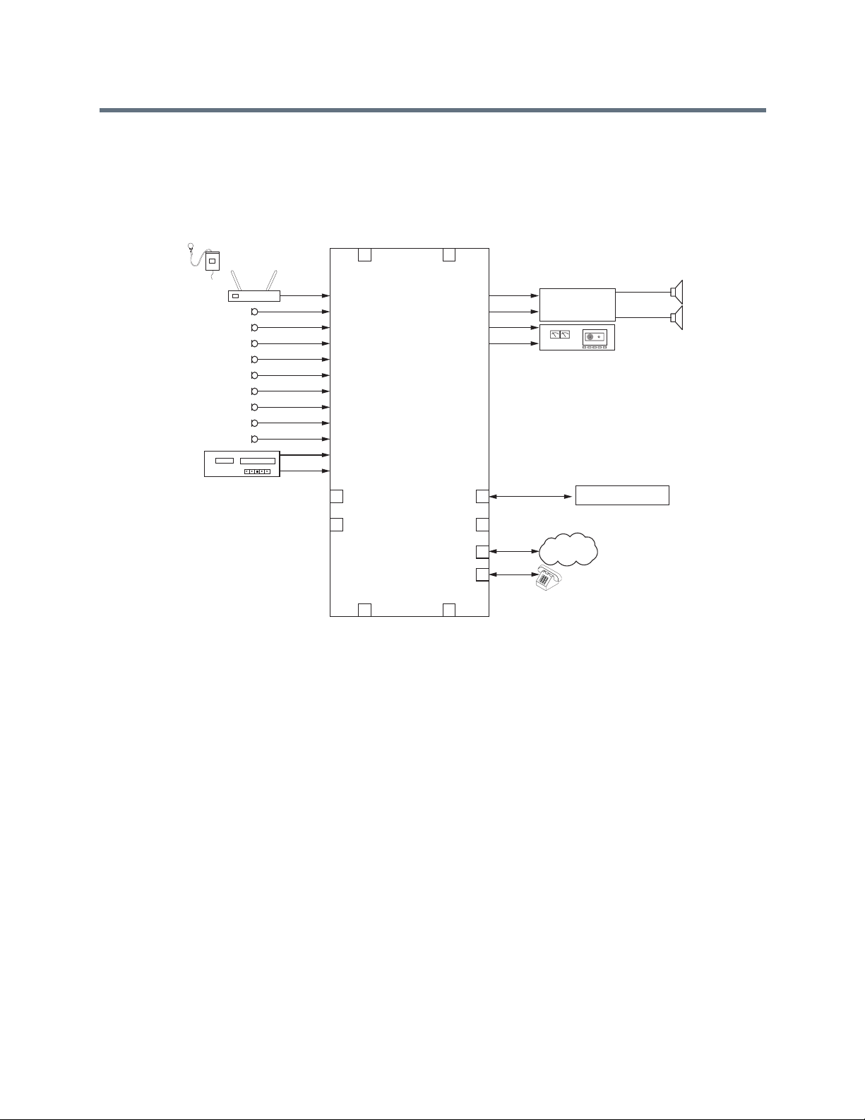
1
2
3
4
5
6
7
8
9
10
11
12
1
2
3
4
5
6
7
8
9
10
11
12
C-LINK2
LOGIC IN LOGIC OUT
C-LINK2
OBAM IN
OBAM OUT
LINE
PHONE
Ethernet
RS-232
SoundStructure
C12
Receiver
12:00 am
VHS
Amplifier
Polycom Video Codec System
Loudspeakers
PSTN
Network
Favorite Content
A
A
Wireless Mic
Amplifier
Record
770-350-4400
To Video Codec
From Video Codec
Podium Mic
Table Mic 1
Table Mic 2
Table Mic 3
Table Mic 4
Table Mic 5
Table Mic 6
Table Mic 7
Table Mic 8
VCR
As an example of using physical channels, virtual channels, and virtual channel groups, consider a
SoundStructure C12 device where there are ten microphone inputs, a telephony interface, and a Polycom
Video Codec system as shown in the following figure.
SoundStructure C12 with Physical Channels, Virtual Channels, and Virtual Channel Groups
In the above example, there is a wireless microphone and a podium microphone, both reinforced into the
room, eight table top microphones, and a stereo VCR for audio playback. As shown in this figure the system
is wired with the wireless microphone in input 1, the podium mic on input 2, the table mics 1-8 on inputs
3-10, a stereo VCR is connected to inputs 11 and 12 and a Polycom Video Codec is connected over the
digital ConferenceLink interface.
Polycom, Inc. 60
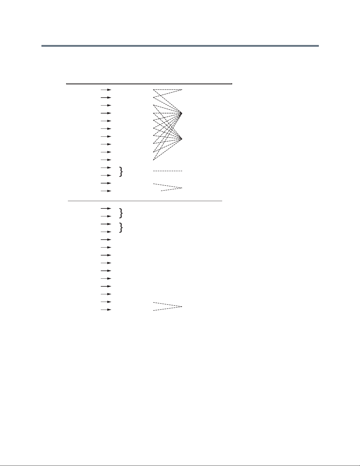
1
2
3
4
5
6
7
8
9
10
11
12
“Wireless mic”
“Podium mic”
“Table mic 1”
“All Mics”
“Reinforced Mics”
“All Table Mics”
“Program Audio”
“Remote Receive Audio”
“Table mic 2”
“Table mic 3”
“Table mic 4”
“Table mic 5”
“Table mic 6”
“Table mic 7”
“Table mic 8”
“VCR”
Physical Channel
Inputs
Outputs
Virtual Channel Virtual Channel Groups
Line “770-350-4400”
CLink2 “From Video Codec”
1
2
3
4
5
6
7
8
9
10
11
12
“Conferencing Amp”
“Remote Send Audio”
“Record”
Line “770-350-4400”
CLink2 “To Video Codec”
Virtual channel definitions are defined, as shown in the following figure.
Virtual Channel Definitions
The virtual channel definitions make it easy to work with the dif ferent signals since each virtual channel has
a specific name and refers to a particular input or ou tput. For instance to take the phone off hook, commands
are sent to the “770-350-4400” virtual channel in this example. If there were multiple telephony interfaces,
each telephony interface would have its own unique virtual channel de finition. It is possible to create a virtual
channel group of multiple telephony virtual channels so all systems could be put onhook together at the end
of a call, etc.
In this example there are several virtual channel groups defined including "Reinforced Mics", "All Mics", "All
Table Mics", "Program Audio", "Remote Receive Audio", and "Remote Send Audio".
Polycom, Inc. 61

Virtual Channel Group Summary
Virtual channel groups are an easy way to create groups of signals that may be controlled together by
sending an API command to the virtual channel group name. It is possible to have more than one virtual
channel group and to have the same virtual channel in multiple virtual channel gr oups. It is also easy to add
or remove signals from the virtual channel group making virtual channel groups the preferred way of
controlling or configuring multiple virtual channels simultaneously.
Virtual channel groups re defined by SoundStructure Studio during the project design steps using the
vcgdef command described in Appendix A. As an example, a virtual channel group with two members,
Table Mic 1 and Table Mic 2, would be defined as:
vcgdef “Zone 1” “Table Mic 1” “Table Mic 2”
Understanding Telephone Virtual Channels
Telephony virtual channels are created with the telephony inputs and telephony outputs - each direction on
a telephony channel is used to create a virtual channel. There are two types of physical channels used:
pstn_in, and pstn_out, in the definition of telephony virtual channels.
By default, SoundStructure Studio creates virtual channel definitions for both the input and output
commands. The command set in Appendix A shows which commands operate on the telephone output
virtual channels and which operate on the telephony input channels.
For example, the phone_connect and phone_dial commands operate on the telephony output channel
while the phone_dial_tone_gain command operates on the telephone input channel.
Defining Logic Pins
SoundStructure logic input and output pins are also considered physical inputs and outputs that can be
abstracted with control virtual channels and control array virtual channels.
Polycom, Inc. 62

Pin 25 Pin 14
Pin 1Pin 13
Pin 1Pin 13
Pin 14Pin 25
Pin Signal
SoundStructure Logic
REMOTE CONTROL 1
REMOTE CONTROL 2
1 +5V
2 Logic output 1
3 Logic output 2
4 Logic output 3
5 Logic output 4
6 Logic output 5
7 Logic output 6
8 Logic output 7
9 Logic output 8
10 Logic output 9
11 Logic output 10
12 Logic output 11
13 Analog gain input 1
Pin Signal
14 Logic input 1
15 Logic input 2
16 Logic input 3
17 Logic input 4
18 Logic input 5
19 Logic input 6
20 Logic input 7
21 Logic input 8
22 Logic input 9
23 Logic input 10
24 Logic input 11
25 Ground
1 +5V
2 Logic output 12
3 Logic output 13
4 Logic output 14
5 Logic output 15
6 Logic output 16
7 Logic output 17
8 Logic output 18
9 Logic output 19
10 Logic output 20
11 Logic output 21
12 Logic output 22
13 Analog gain input 2
14 Logic input 12
15 Logic input 13
16 Logic input 14
17 Logic input 15
18 Logic input 16
19 Logic input 17
20 Logic input 18
21 Logic input 19
22 Logic input 20
23 Logic input 21
24 Logic input 22
25 Ground
Labeling Physical Logic Pins
The physical logic pins and labeling are shown in the following figure.
Physical Logic Pins and Labeling
REMOTE CONTROL 1
REMOTE CONTROL 2
The logic inputs and logic outputs have physical inputs and outputs 1 - 11 on Remot e Con tr ol 1 con n ec tor
and 12 - 22 on Remote Control 2 connector on each SoundStructure device.
When multiple devices are OBAM linked, as shown in the next figure, the logic inputs and outputs on the
first device are numbered 1 - 22 and the logic inputs and outputs on the second device (device B) are
Polycom, Inc. 63

PIN 2: TXD
PIN 3: RXD
PIN 5: GROUND
PIN 7: CTS
PIN 8: RTS
OBAM IR
RS-232
REMOTE CONTROL 2
IN OUT
12V
REMOTE CONTROL 1
PIN 2: TXD
PIN 3: RXD
PIN 5: GROUND
PIN 7: CTS
PIN 8: RTS
OBAM IR
RS-232
REMOTE CONTROL 2
IN OUT
12V
REMOTE CONTROL 1
PIN 2: TXD
PIN 3: RXD
PIN 5: GROUND
PIN 7: CTS
PIN 8: RTS
OBAM IR
RS-232
REMOTE CONTROL 2
IN OUT
12V
REMOTE CONTROL 1
Logic Outputs 23 - 33
Logic Outputs 23 - 33
Logic Outputs 34 - 44
Logic Outputs 1 - 11Analog Gain Input 1
Logic Outputs 12 - 22
Logic Outputs 34 - 44
Analog Gain Input 2
Analog Gain Input 3
Analog Gain Input 4
Analog Gain Input 5
Analog Gain Input 6
numbered 23 - 44, and so on. The analog gain inputs are n umbered 1 and 2 on the first device, 3 and 4 o n
the second device, and so on.
Numbering of Logic Inputs and Outputs on an OBAM Linked SoundStructure Device
Due to the one large system design philosophy, logic input pins on any device can be used to control
features on any SoundStructure device - not just provide control on the device the logic inputs are on.
Similarly logic outputs can be used to provide status on signals on any SoundStructure device - not just
status on a physical channel on that particular device.
Polycom, Inc. 64

Logic
Status
SoundStructure Logic Input
Logic Input Pin
Logic Pin 25 (Ground)
3.3V
Logic Inputs
All digital logic inputs (logic inputs 1 - 22) operate as contact closures and can be connected to ground
(closed) or not connected to ground (open). The logic input circ uitry is shown in the following figure. The
default value for logic inputs is 1 due to the pull up resistor. The value for the pin changes to 0 when the pin
is shorted to ground. The value of the logic pin is read or written with the digital_gpio_value
parameter. See Using Events, Logic, and IR and Appendix A: Command Protocol Reference Gu ide for more
details.
Logic Input Circuitry for SoundStructure Devices
Analog Gain Input
The analog gain inputs (analog gain 1 and 2) operate by meas uring an a nalog voltage between the a nalog
input pin and the ground pin. The maximum input voltage level sh ould not exceed +6 V. It is recommended
that the +5 V supply on Pin 1 be used as the upper voltage limit.
The next figure shows the analog gain input pin and the associated +5 V and ground pins that are used with
the analog gain input pin. The analog voltage on th e analog gain input pin is converted to a digital value via
an analog-to-digital converter for use within th e Soun dStructure devices. The maximum voltage valu e, that
Polycom, Inc. 65

Analog
Voltage
Value
SoundStructure Logic Input
Analog Gain Input Pin
Logic Pin 25 (Ground)
Logic Pin 1 (+5V)
5V
Logic
Controller
SoundStructure Logic Output
Logic Output Pin
Chassis
Ground
is, 0 dBFS on the analog gain input, is 4.096 V. 0V is converted to 0 and 4.096 V and above is converted to
255.
Analog Gain Input Pin for SoundStructure Devices
Logic Outputs
All logic outputs are configured as open-collector circuits and can be used with external positive voltage
sources. The maximum voltage that should be used with the logic outputs is 60 V. Each pin can sink up to
60mA. When using the internal 5V power supply, the maximum current that is supplied across all logic
outputs on a SoundStructure device is 500 mA.
Logic Output Pin on SoundStructure Devices
The open collector design is shown in the following figure an d works as a switch as follows: when the logic
output pin is set high (on), the transistor turns on and the signal connected to the logic outp ut pin is
grounded and current flows from the logic output pin to chassis ground.
Polycom, Inc. 66

Logic Output = 0
Low (Off)
Logic Output = 1
High (On)
Chassis GroundChassis Ground
Logic Output PinLogic Output Pin
When the logic output is set low (off), the transistor turns off and an open circuit is created between the logic
output and the chassis ground preventing any flow of current, as shown in the following figure.
Logic Output Pin Set to Low (Off)
Examples of using logic input and output pins may be found in Using Events, Logic, and IR of this guide.
Controlling Virtual Channels
The concept of virtual channels also applies to the logic inputs and outputs. The A/V designer can create
control virtual channels that consist of a logic input or outpu t pin .
Logic pins can be defined via the command line interface from SoundStructure Studio or a control terminal
with the following syntax to define a logic input on logic input pin 1:
vcdef “Logic Input Example” control digital_gpio_in 1
which returns the acknowledgment
vcdef "Logic Input Example" control digital_gpio_in 1
A logic output pin definition using output pin 1 is created with the command:
vcdef "Logic Output Example" control digital_gpio_out 1
which returns the acknowledgment
vcdef "Logic Output Example" control digital_gpio_out 1
Once defined, the designer can refer to those control virtual channels by their name. As with the example
above, the designer created a control input virtual channel “Logic Input Example”. The SoundStructure
device can be queried with a control system to determine the value of the logic pin and when it is active, it
could be used to change the status of the device. When the “Logic Inpu t Example” input is inactive, it could,
for example, be used with an external control system to unmu te the microphones. In version 1.0 of the
firmware logic pins must be queried by an external control system and then the control system can execute
commands or a series of commands on the device.
The value of control virtual channels may be queried by the control system by using the command
digital_gpio_state. An example of this is shown below.
get digital_gpio_state “Logic Input Example”
The state of digital logic output may also be set active using the digital_gpio_state command as
follows for the control virtual channel “Logic Output Example” that would be created with the vcdef
command.
Polycom, Inc. 67

set digital_gpio_state “Logic Output Example” 1
Additional information about using logic pins may be found in Appendix A.
Controlling Array Virtual Channels
Multiple logic pins may be associated together with a control array virtual channel. Control array virtual
channels are created by one or more logic input or log ic output pins. Once a control array channel is defined,
the value of the group of pins can be queried or set using the digital_gpio_value command.
The value of the digital control array is the binary sum of the individual logic pins. For example, if a control
array virtual channel is defined with digital outp ut pins 2, 3, and 4, then the value of the control array channel
is in the range of 0 to 7 with physical logic pin 4 as the most significant bit and physical logic pin 2 as the
least significant bit.
As an example, consider a control array named “logic arr ay” that u ses physical logic input pins 2, 3, and 4
that is created with the following syntax:
vcdef “logic array” control_array digital_gpio_in 2 3 4
which returns the command acknowledgment:
vcdef "logic array" control_array digital_gpio_in 2 3 4
In this example, three input pins have been specified with pin 2 first and pin 4 listed last. The value of the
digital input array can be queried using the get action:
get digital_gpio_value "logic array"
val digital_gpio_value "logic array" 7
The value of the logic array depends on the value of the individual logic input pins 4, 3, and 2. A logic pin
has a value of 0 when that the pin is shorted to ground and a value of 1 when that pin is open.
The order that the pins are listed in the control array definition is defin ed so that the last pin specified is the
most significant bit and the first pin specified is the least significant bit. For the example above where the
control array was defined with pins 2 3 4, the 3-bit value is formed by using pin 4 as the most significant bit,
pin 3 as the next bit, and pin 2 as the least significant bit.
Control Array and Logic Input Pin Values
Control Array Value Pin 4 Pin 3 Pin 2
7 111
6 110
5 101
4 100
3 011
2 010
1 001
0 000
In the above table, if all the pins are open, the get command descri bed above returns the value 7. If pin 2 is
shorted to ground (value of 0), the value of the get command is 6 and so forth.
Polycom, Inc. 68

A control array of logic output pins may be specified with the same syntax as in the previous example
substituting digital_gpio_out for digital_gpio_in.
See Using Events, Logic, and IR and Appendix A: Command Protocol Reference Guide for more
information on control array virtual channels.
Understanding IR Receiver Virtual Channel
The IR receiver input on the SoundStructure device responds with acknowled gments when a valid IR signal
is received. The first step towards using the IR receiver is to define the IR receive r virtual channe l. This can
be done with the following syntax:
vcdef “IR input” control ir_in 1
where 1 is the only physical channel that can be specified since there is only one physical IR receiver
channel.
Once a command from the Polycom IR remote transmitter, a command acknowledgment of the form:
val ir_key_press “IR Input” 58
is generated by the SoundStructure device when a key that corresponds to code 58 is pressed on the IR
remote transmitter. The infrared remote controller ID must be set to the factory default of 3 for the IR receiver
to properly identify the command.
See Using Events, Logic, and IR for information about how to use the IR receiver with SoundStructure
events.
Polycom, Inc. 69

Creating Designs with SoundStructure Studio
A SoundStruc ture configuration file is a binary file that includes the definition of the virtual channels, the
virtual channel groups, the appropriate input and output gain settings, echo cancellation settings,
equalization, matrix routings, and more. This file m ay be uploaded to SoundStructure d evices or stored on
the local PC for later upload.
By default, SoundStructure products do not have prede fined virtual channels or a predefined matrix routing
and therefore must be configured before the SoundStructure products can be used in audio applications.
The SoundStructure Studio software with integrated InstantDesigner
upload that design to one or more SoundStructure devices.
Note: No Default Configuration for SoundStructure Systems
SoundStructure devices are shipped without a default configuration and must be
configured with the SoundStructure Studio software.
The details of creating a new SoundStructure Studio design file are described in this chapter . For information
on how to customize a design file, see Customizing SoundStructure Designs and for information on how to
use the specific user interface controls with SoundStructure Studio, see Using SoundStructure Studio
Controls.
To create a new SoundStructure Studio project, follow these steps:
™
is used to create a design and to
1 Launch SoundStructure Studio and select New Project from the file menu
2 Follow the on-screen steps to specify the input signals
3 Follow the on-screen steps to specify the output signals
4 Select the SoundStructure devices to be used for the design
5 Create the configuration and optionally upload to the SoundStructure devices
These steps are described in more detail in the following section.
Understanding SoundStructure Studio
The first step to creating a SoundStructure design is to launch the SoundStr ucture Studio application. If the
SoundStructure Studio software is not already installed on the local PC, it may be installed from the CD that
was included with the product. More recent versions of SoundStructure Studio may also be available on the
Polycom website - please check the Polycom website before installing the SoundStructure Studio version
that is on the CD-ROM.
Polycom, Inc. 70

Understanding System Requirements
SoundStructure Studio is supported on Micros of t® Windows XP w/ Service Pack 2 and higher, Microsoft
Windows Vista, and Microsoft Windows 7.
SoundStructure Studio requires:
● Microsoft .NET Framework 2.0, which requires 280MB of disk space on an x86 computer
architecture, and 610MB on x64 computer architecture
● 40MB of disk space
● 512MB of memory
● A display with 1024x768 re solution.
● A network interface card (wired or wireless) or serial port to connect to SoundStructure devices
Viewing Recommended Operating System
The recommended system for operating SoundStructure Studio has the following characteristics:
● 1GB or higher of memory
● A display with 1280x1024 resolution or higher
Installing SoundStructure Studio
To install SoundStructure Studio,
1 Run the StudioSetup.exe software and follow the prompts.
2 After Studio is installed, launch SoundStructure Studio and select File > New Project, as shown in
following figure.
Polycom, Inc. 71

Step 1 - Input Signals
Creating a new project displays the Create a Project window , as shown in the following figure. The first step
of the design process is to select the inputs to the system.
Creating A Project Dialog in SoundStructure Studio
To create a SoundStructure design:
1 Select the style of input (Microphone, Program Audio, etc.), and specify the type of input (Ceiling,
Lectern, etc.) and the quantity of the input
2 Click “Add”.
The label of the input signal becomes the virtual channel name of tha t input signal. A signal generator
is added by default to all projects.
SoundStructure Studio provides a number of pr edefined input types including microph ones, program audio
sources, video codecs, telephony interfaces, submixes, and a signal generator.
SoundStructure Studio provides default input gains for the various input and output channels. After the
design has been created, these gains, along with all other settings, can be adjuste d as described in
Customizing SoundStructure Designs.
Polycom, Inc. 72

For more information on integration with table and ceiling microphones, see the Best Practices Guide:
Polycom SoundStructure and Polycom Microphones.
The choices for Hybrids/Codecs include the Polycom Video Codec, the Polycom VSX series, and a generic
mono or stereo video codec. When the Polycom Video Codec is selected, it is assumed that the Polycom
Video Codec connects to the SoundStructure device over the Conference Link2 interface. To use the
Polycom Video Codec with the SoundStructure devices via the analog input and output instead of
Conference Link requires selecting a different codec such as the VSX8000 stereo codec. Connecting Over
Conference Link2 provides additional information about integrating with the Polycom Video Codec over the
Conference Link2 interface.
A typical system is shown in the next figure where a stereo program audio source, eight table microphones,
a wireless microphone, a telephony input, and a Polycom Video Codec have been selected.
Example Project Created in SoundStructure Studio
The graphic icon next to the signal name in the Channels Defined: field indicates whether the virtual channel
is a monaural channel that is defined with one physical chan ne l (a dot with two wa ves on one side) or a
stereo virtual channel that is defined with two physical channels (a dot with two waves on both sides).
When a Polycom Video Codec is selected, there are mult iple audio channels that are created automatically
and used independently in the SoundStructure matrix. See Connecting Over Conference Li nk2 for
additional information on the audio channels and the processing that is available on these channels.
Polycom, Inc. 73

When a video codec or telephony option is selected, the corresponding output signal automatically appear s
in the outputs page as well.
You can delete Channels by selecting the channel in the Channels Defined: field and clicking Remove.
Step 2 - Output Signals
In step 2 of the design process, the outputs from the system are specified in the same manner that inputs
were created. A sample collection of outputs is shown in the following figure.
A Sample Collection of Outputs In SoundStructure Studio
The outputs include audio amplifiers, recording devices, assistive listening devices, and also other
telephony or video codec systems. If the desired style of outputs is not found, select something close and
then customize the settings as described in Customizing SoundStructure Designs.
In this example, a stereo amplifier was selected as well as a mono recording output. The telephone and
Polycom Video Codec conferencing system outputs were automatically created when their respective inputs
were added to the system. Notice that there are multiple audio channels associated with the Polycom V ideo
Codec. See Connecting Over Conference Link2 for additional information.
Polycom, Inc. 74
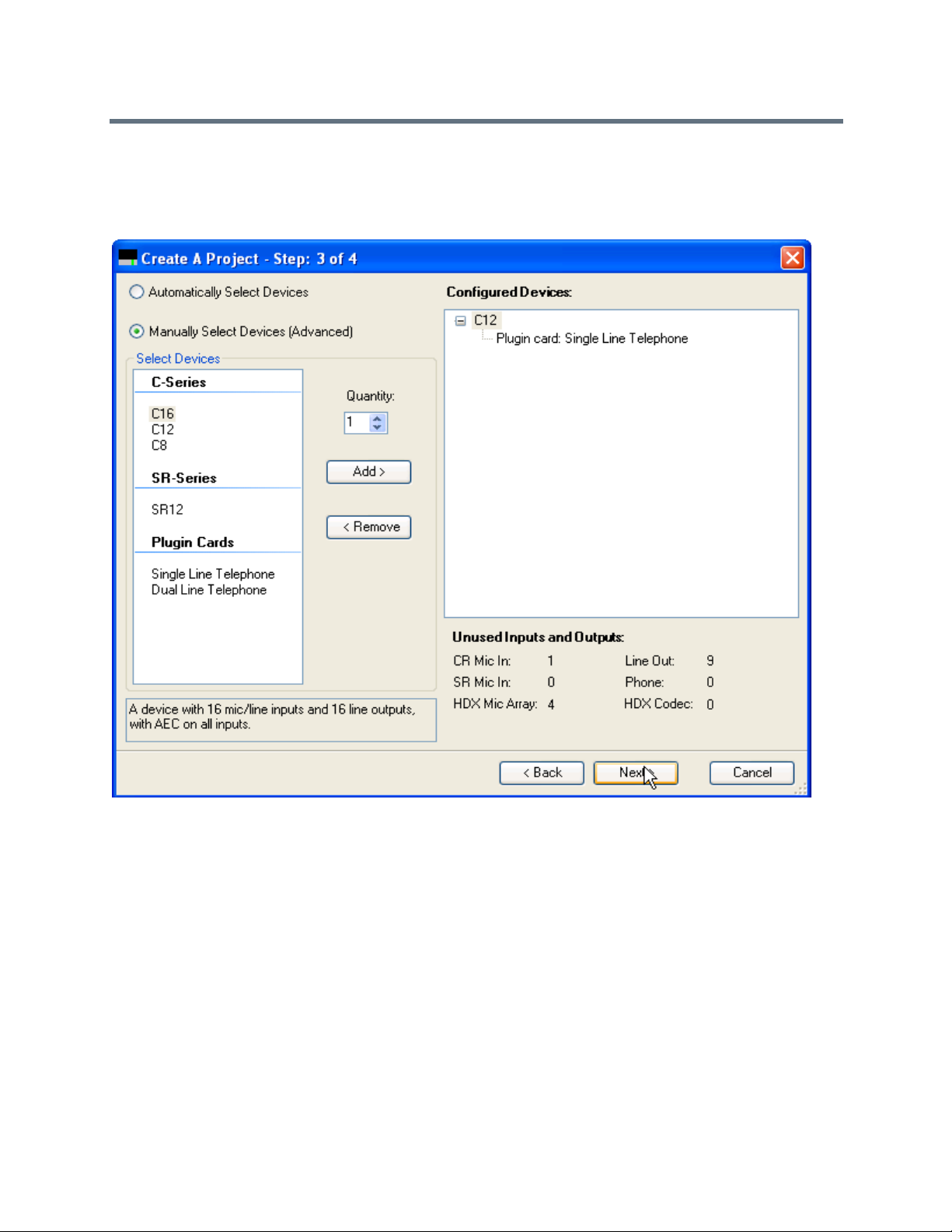
Step 3 - Device Selection
In Step 3, select the devices that you are using with the design project, as shown in the following figure.
Selecting Devices to be Used with a Design Project
By default, SoundStructure Studio displays the equipment with the minimum list price although it is possible
to manually select the devices by selecting the Manually Select Devices option and adding devices and
optional telephony cards.
Y ou can select differ ent devices by clicking on the device, adjusting the quantity, and clicking “Add”. Y ou can
remove devices by selecting the device in the Configured Devices window and selecting Remove.
The unused inputs and outputs display whether additional resources are r equired to imple ment the design
and also how many unused inputs and outputs are available.
In this example, a SoundStructure C12 and a single-line telephony inter face card are selected to implement
the design. The resulting system has one addition al analog input and nine additional analog outputs. The
inputs are used by the eight microphones, one wireless microphone , and the stereo progra m audio and the
line outputs are used by the stereo amplifier and the mono recorder. The Polycom Video Codec does not
require any analog inputs and outputs because the si gnals are transferred over the digital Confere nce Link2
interface.
Polycom, Inc. 75

Step 4 - Uploading Or Working Offline
In step 4, you can decide to either work of fline or wo rk online. When work ing online, you can sele ct a set of
devices to upload the settings to via the Ethernet or RS-232 interfaces. As a best practice, Polycom
recommends you design the file offline, customize settings - including the wiring page as described in the
Customizing SoundStructure Designs if the system has already been cabled, and upload the settings to the
device for final online adjustments.
In this example, the design file is created offline for offline configuration and later uploaded to the device.
Creating Design Projects Offline
To find devices on the network:
1 Select Send configuration to devices.
SoundStructure Studio searches for devices on the local LAN as d efined by the Ethern et interfac e’ s
subnet mask or the RS-232 interface. See Installing SoundStructure Devices for additional
information on uploading and downloading configuration files a nd Appendix B: Address Book for how
to use the Address Book functionality.
2 Click Finish.
SoundStructure Studio creates a design file including defining all the virtual channels and virtual
channel groups such as those shown the following figure.
Polycom, Inc. 76
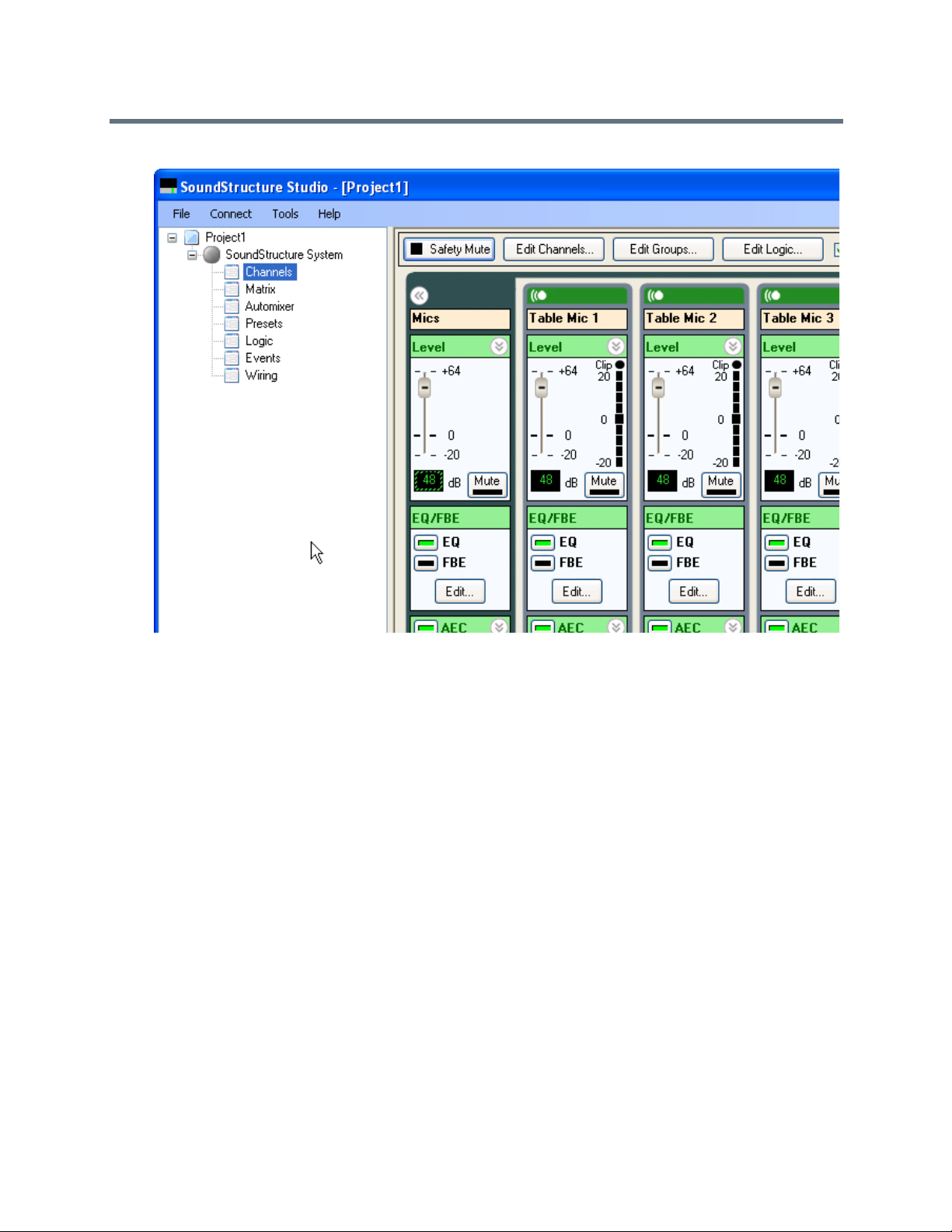
The Customizing SoundStructure Designs describes how to custom ize the SoundStructure device settings.
If working online, the Ethernet port on the project tree on the left of the screen displays a large green dot
next to the device name. When working offline there is a gray dot next to the device name.
Operating in Online and Offline Mode
SoundStructure Studio has been designed to fully operat e in either online or offline modes. Online operation
means that SoundStructure Studio is communicating with one or more SoundStructure devices, sending
commands to the devices, and receiving command acknowledgments from the devices. Every change to
the SoundStructure design is made in real-time to the actual devices. There is no requirement to compile
any SoundStructure Studio code before the impact can be heard.
Offline operation means that SoundStructure Studio is working with an emulation of the SoundStructure
devices and is not communicating with actual SoundStructure devices. Commands are sent to the emulator
and command acknowledgments receive commands from the emulator allowing the designer to test a
SoundStructure system design without ever connecting to a system.
Polycom, Inc. 77

Regardless of whether the system is operating online or offline with SoundStructure Studio, you can open
the SoundStructure Studio Console and see the commands and acknowled gme nts by ri ght clicking on the
control port interface as shown in the following figures.
SoundStructure Studio Console
SoundStructure Studio Data Console
Polycom, Inc. 78

In this example, the virtual channel group “Mics” are muted and the console shows the command in blue
and the acknowledgments generated in green.
When SoundStructure Studio is working offline, the prefix [Offline]: is shown in the console as a reminder
that commands are not being sent to actual devices. While offline, comma nd s ar e se nt to the
SoundStructure device emulator using the command syntax described in Appendix A: Command Protocol
Reference Guide and acknowledgments are received just as if communicating to actual systems.
Offline operation is commonly used prior to the actual installation of the physical SoundStructure devices to
adjust the system before on site installation, or when a physical device is not readily accessible.
Note: Working Offline with SoundStructure Studio
With SoundStructure Studio, it is possible to work offline and fully emulate the
operation of the SoundStructure devices. You can send commands to the system,
the system receives acknowledgments, and the system operation including presets,
signal gains, matrix crosspoints, and more are tested without ever connecting to
SoundStructure devices.
When working offline, you can save the configuration file at any time by selecting File > Save Project. This
creates the file with the name of your choosing and stores the file on the local disk with the .str file extension.
When working online, saving the project prompts you to save the file on th e disk as well as store the settings
in the SoundStructure device.
Polycom, Inc. 79

Customizing SoundStructure Designs
After you create a SoundStructure project file as described in Creating Designs with SoundStructure Studio,
you can use the SoundStructure Studio software to adju st and customize the design. This section provides
you with in-depth instructions on how to customize the set tin gs by using the Wiring, Channels, Matrix,
Telephony, and Automixer pages. For information on uploading and downloading configuration files, see
Installing SoundStructure Devices.
The detailed controls for the inputs, outputs, and submix signals are presented in the order that the controls
appear on the channels page.
After you make changes to the configuration, ensure that the settings are stored to a preset (see Installing
SoundStructure Devices) and that you define a power on preset.
Using the Wiring Page
During the design process, SoundStructu re Stud io creates the virtual input and output channels using the
labels that were used during design steps 1 and 2 in Creating Designs with SoundStructure Studio as the
virtual channel names. The virtual channels are created with default physical input and output channels
which are assigned automatically based on the order that the virtual channels are added to the system
during the first two design steps. Changing the order that inputs and outputs are selected changes the
default physical channel assignments.
The wiring page is where the SoundStructure Studio wiring assignment are reviewed an d changed if
SoundStructure Studio wired the system with different inputs and outputs than expected or desired.
As shown in the example in the following figure, the six table top microphones use physical inputs 1 - 6, th e
program audio uses inputs 7 and 8 and the wireless micr ophone uses input 9. On the outputs, the amplifier
stereo virtual channel uses physical channels 1 and 2 and the recording channel uses physical output 3.
Remember that stereo virtual channels are always defined with two physical channels while mono virtual
channels are defined with one physical channel.
Polycom, Inc. 80

The following figure shows the default wiring for an example that the system created with six table top
microphones, stereo program audio, and a wireless microphone.
An Example SoundStructure Device with Default Wiring
If it is necessary to change the wiring from the default wiring, you can change the virtual wiring by clicking
and dragging signals from their current input or output to a new input or output, as shown in the following
figure. In this example, the Recording output changed from physical output 3 to physical output 6.
Polycom, Inc. 81

Editing Default Wiring in SoundStructure Studi o
When a virtual channel is moved, SoundStructure Studio redefines the virtual channel to use the new
physical inputs or outputs that are specified. Moving a virtual channel does not cr eate any visible ch ang es
in the Matrix or Channels page because SoundStructure Studio operates at the level of the virtual channel
and not the physical channels. The only page that displays a difference is the Wiring page.
It is important to know that the actual wiring of the system needs to match the wiring specified on the Wiring
page. Otherwise, the system does not operate as expected. For instance, in the example above, if the
recording output is physically plugged into output 3 when SoundStructure Studio notices the recording
Polycom, Inc. 82

output is plugged into output 6, no audio is heard on output 3 because the au dio is being routed to physical
output 6.
Note: Matching Physical Channel Wiring
For proper system operation, make sure the physical channel wiring matches the
wiring instructions on the Channel page. You can make adjustments to the wiring by
physically moving connections to match the Wiring page, or by moving signals on
the Wiring page to match the physical connections.
Editing Devices
When working offline, the Wiring Page includes an Edit Devices control for changing the underlying
SoundStructure equipment that was selected duri ng the design process, as shown in the following figure.
Edit Devices in SoundStructure Studio
You can do the following with the Edit Devices control:
● Grow a project from a smaller SoundStructure device to a larger device
● Shrink a project from a larger SoundStructure device to a smaller device, if there ar e enough unused
inputs and outputs
● Add, change, or remove telephony cards
Polycom, Inc. 83

The Edit Devices control that displays is the same control that was used during the original design process
and is shown below.
Edit Devices Page in SoundStructure Studio
To reduce the equipment on a project that has too many inputs or outputs to fit into the next smaller
SoundStructure device requires removing audio channels from the Edit Channel cont rol.
Using the Channels Page
The Channels page is the primary area for customizing the signal gains and proce ssing for the input, output,
and submix signals. Regardless of the number of SoundStructure devices used in a design, there is only
Polycom, Inc. 84

one Channels page and that page displays all the virtual channels for the entire design. A typical Channels
page is shown in the following figure.
Channels Page in SoundStructure Studio
The input and output signals are shown with dif ferent colored outlines to differentiate among inputs, outpu ts,
and submixes. The signals are color coded with the input signals having a green shading and outline, the
Polycom, Inc. 85

output signals having a blue shading and outline to match the rear-panel labeling, and the submixes have
a purple shading and outline, as shown in the following figure.
Color Coding for Inputs, Outputs, and Submixes on the Channels Page in SoundStructure Studio
Y ou can change which types of virtual channels ar e viewed by enabling or disabling groups, inputs, outputs,
and submixes with the controls on the top of the Channels page as shown in the following figure.
Editing Controls on the Channels Page in SoundStructure Studio
In addition, you can expand groups of virtual channels to display the individual members of the group by
Polycom, Inc. 86

clicking Expand All or collapse the channels to only show the virtual channel groups by clicking Collapse
All, as shown in the following figure.
Editing Controls on the Channels Page in SoundStructure Studio
Note: Adjusting Virtual Channel Settings
Any of the settings for virtual channels can be adjusted by either adjusting the
virtual channels individually or by adjusting the virtual channel group settings.
Editing Virtual Channels
You can add or delete additional virtual channels by clicking Edit Channels on the Channels page as
highlighted in the following figure. You can adjust designs to add more inputs or outputs up to the limit of the
number of physical inputs and outputs of the hardware that was selected to implement the design.
Editing Channels on the Channels Page in SoundStructure Studio
The Edit Channels button opens the input and output channel selectio n window and enable s you to add or
remove virtual channels, as shown in the following figure. If virtual channels are added, the channels display
on the Channels page with default gain settings for the devices and default signal routing created for the
matrix based on the type of signal added. If virtual channels are deleted, the channels are removed from
the Channels page and the channels’ matrix signal routings are removed.
Polycom, Inc. 87

Monaural Stereo
The Edit Channels Page in SoundStructure Studio
There is a graphic symbol, see the following figure, at the top of each virtual channel as a reminder of
whether the virtual channel is a monaural or stereo virtual channel.
Monaural and Stereo Virtual Channel Symbols
This graphic symbol is also shown on the Edit Channels page associated with each channel in the
‘Channels Defined:’ column.
Creating Virtual Channel Groups
Virtual channel groups are collections of virtual channe ls that you can configure together. When creating a
new project, a virtual channel group called “Mics” is automatically created and includes all the micr ophone
inputs for the design. The virtual channel group can be used to adjust all the settings for all the signals in
the virtual group regardless of whether the group is expanded or contracted.
A virtual cha nnel group may be collapsed or expanded by clicking the graphics respectively, on
the top of the group page. All groups in the cha nnels page can be expand ed or collapsed by clicking on th e
Expand or Collapse buttons respectively.
Polycom, Inc. 88

To create additional virtual channel groups:
» Click Edit Groups on the Channels page.
All existing virtual channel groups display on the right of the screen. V irtual channels can be in more
than one virtual channel group. For example, Table Mic 1 can be in the virtual channel group Mics
and Zone 1 Mics.
Polycom, Inc. 89
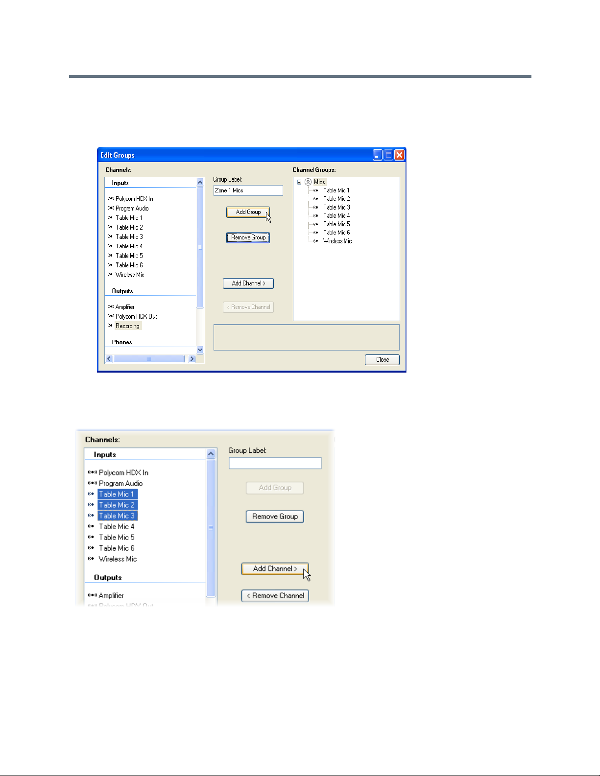
To add a new virtual channel group:
» Enter a group name in the Group Label: field and click Add Group, as shown in the following figures.
This figure shows an example of creating the Zone 1 Mics virtual channel group.
After you define a virtual channel group, you can add virtual channels to the virtual channel group by
selecting the desired virtual channels. You can select more than one virtual channel by left clicking on the
first channel and holding shift while you click on subsequent virtual channels. After you select the virtual
channels, click Add Channel, as shown in the following figure.
Any commands sent to configure the virtual channel group are sent to the members of the virtual channel
group. For example, if a mute command is sent to Zone 1 Mics then Table Mic 1, Table Mic 2, and Table Mic
3 are all muted and the Zone 1 Mics logical group display as muted.
If individual members of a group have different values for the same parameter, such as the mute state, the
value of the group parameter displays with a crosshatch pattern, as shown in the following figur es.
Polycom, Inc. 90

Virtual Channels Muted
If the Mics group is unmuted and the Zone 1 Mics group is muted, the mute status of the Zone 1 Mics
displays the mute status and the Mics group displays a mixed mute state because some microphones in the
group are still muted but others are unmuted. The mixed mute state is shown as a cross hatched bar in the
mute button.
Notice in the above figure that the gain for the microphone inputs in the Mics group displays as 43 with
dashed lines around it indicates that some - but not all - of the microphones have a gain of 43 dB. In this
example, the wireless microphone has a different gain value. The group displays a dashed line if all the
values are not the same for the members in the group. In the above figure, all the members of the Zone 1
Mics group have 48 dB of gain, so there are no dashed lines around the gain for the Zone 1 Mics group.
Note: Changing Virtual Channels and Groups
Changing virtual channel group settings changes all the settings for the virtual
channels that are a part of the virtual channel group and generate command
acknowledgments for the virtual channel group and its virtual channels members.
If a parameter for all members of a virtual channel group is individually changed to the same value, the
virtual channel group setting does not set automatically to the common value and consequently are no
command acknowledgment that the virtual channel group has that common value. For instance, if all
microphones in the Zone 1 group are muted individually, the Zone 1 group does not acknowledge that the
group is muted. However, if the Zone 1 group is muted, Zone 1 group acknowledges that the g roup and all
the members of the group are in a muted state.
Note: Individually Changing Members in a Virtual Channel Group
Changing the settings of all members in the group individually to a common value
does not cause the virtual channel group to show that common value.
Setting Input Signals
The settings applied to input signals depend on the type of virtual channel created from that physical input.
For example, there are different controls if the signal is a microphone input, line le vel input, a stereo virtual
channel, a signal generator, or a telco input.
Polycom, Inc. 91
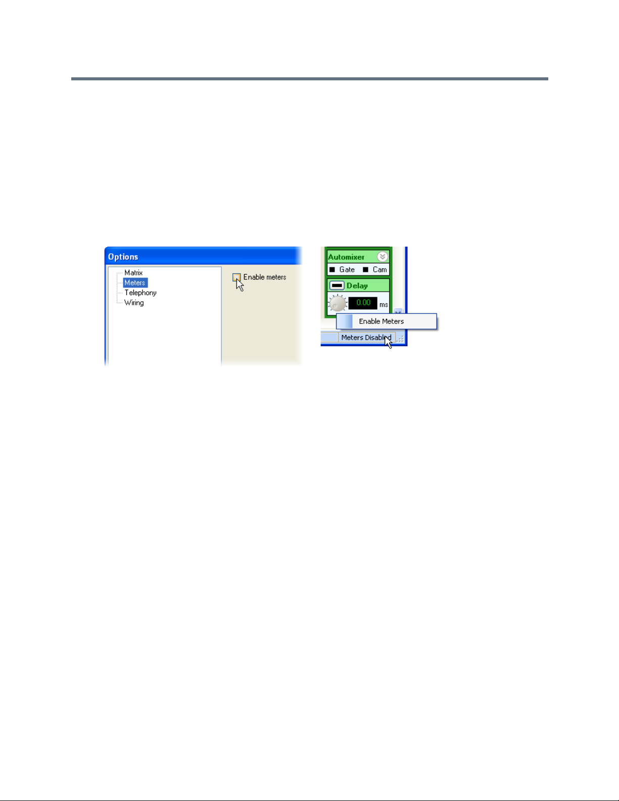
Enabling Input Signal Meters
All input signals have meters that display the signal activity. The meters are enabled from the Tools menu
or from the lower right hand corner of the screen.
To enable the signal meters from the Tools menu:
1 Select Tools > Options.
2 Choose the meters entry and select Enable Meters.
You can also enable meters by right clicking on the lower right hand corner of the screen and select
the desired meter state. Both options are shown in the following figure.
Enabling meters is a function of SoundStructure Studio and not the particular configuration file . This means
that when you enable meters, the meters are enabled for al l projects that SoundStructure Studio opens from
then on.
After you enable meters and navigate to a page that displays the meter activity (such as the Channels page),
the desired signal meters are automatically registered b y SoundStructure Studio and the meter d ata is sent
from the SoundStructure device to SoundStructure Studio. Navigating away from a page with meter
information causes the meters unregister and any new meters on the new page are registered.
SoundStructure Studio uses the mtrreg and mtrunreg commands to automatically register and unregister
meters, respectively
You can view meter information either over RS-232 or Ethernet connections to the SoundStructure device;
however, the meters are most responsive over a Ethernet connection. If meters are viewed o ver the RS-232
interface, Polycom recommends that you use the highest data rate of 115,200 baud to minimize any lag
between registering for meters and having the meter information displayed on the screen.
Understanding Meter Types
There are typically two types for meters that are availab le for each input channel - a level that is before any
processing known as a level_pre and a level that is after any input processing known as level_post.
The level_pre meter always displays the signal level just after the A/D converter. This meter shows the
effect of the analog signal gain before any digital processing takes place, as shown in the following figure.
Polycom, Inc. 92

Equalization
A/D
Converter
Analog
Gain
level_pre
level_pre
Installing SoundStructure Devices discusses how the analog gain should be set for best performance. The
level_pre for all input signals is shown in the following figure.
Analog Gain Signal Before (level_pre) Digital Processing
Mic or Line
Input
C-Series Input Processing
A/D
Parametric
Analog
Converter
Gain
Equalization
Acoustic Echo
Cancellation
Noise
Cancellation
Non Linear
Processing
Feedback
Cancellation
Router
AGC Dynamics Fader Delay
Automatic
Gain Control
Automatic
Gain Control
Automatic
Gain Control
Dynamics
Processor
Dynamics
Processor
Dynamics
Processor
Automixer
Automixer
Automixer
Fader Delay
Fader
Fader
Mute
Delay
Delay
Input to
Recording/
Matrix
Ungated
Input to
Conferencing
Matrix
Sound
Input to
Matrix
Reinforcement
The level_pre signal meter is adjacent to the analog input gain slider in So undStructure Studio, as shown
in the following figure. Ad justments to the gain slider are reflected in the meter - add more gain and the meter
displays more signal activity; lower the gain, and the meter displays less signal activity.
The level_pre Signal Meter in SoundStructure Studio
Because the level_pre meter position is before any processing is applied to the signal, even if the signal is
muted within the SoundStructure device, the level_pre input meter displays any signal activity on that
input.
The level_post meter is after any processing, as shown in the following figure. In the example below, if
the input signal is muted the level_post meter does not display any signal activity.
The exact location of the meter in the signal processing path depends on the type of signal that is viewed,
as described next.
Polycom, Inc. 93

Input to
Matrix
Input to
Matrix
Input to
Matrix
Mute
Recording/
Ungated
Conferencing
Sound
Reinforcement
Microphone Post Processing Meter
level_post
level_post
Measuring Microphone Post Levels
Microphone channels post level measure the signal level at the conferencing ou tput of the input processing,
as shown in the following figure.
Microphone Post Level Processing in SoundStructure Studio
Mic or Line
C-Series Input Processing
A/D
Parametric
Analog
Input
Converter
Gain
Equalization
Acoustic Echo
Cancellation
Noise
Cancellation
Non Linear
Processing
Feedback
Cancellation
Router
AGC Dynamics Fader Delay
Automatic
Gain Control
Automatic
Gain Control
Automatic
Gain Control
Dynamics
Processor
Dynamics
Processor
Dynamics
Processor
Automixer
Automixer
Automixer
Fader Delay
Fader
Fader
Mute
Input to
Recording/
Matrix
Ungated
Delay
Delay
Input to
Conferencing
Matrix
Sound
Input to
Matrix
Reinforcement
You can use the fader on the bottom of the input channel to adjust the gain of the output of the input
processing. The fader changes the level of all three outputs going to the matrix. The meter activity displays
the affect of any gain adjustments.
Polycom, Inc. 94

Input to
Matrix
Input to
Matrix
Input to
Matrix
Mute
Recording/
Ungated
Conferencing
Sound
Reinforcement
Line Input Post Processing Meter
level_post
level_post
Input and Output Fader in SoundStructure Studio
Metering Line Input Post Levels
Line input channels, such as program audio or audio from video codecs that are connected via analog inputs
and outputs, are metered at the Record ing/Ungated outp ut, as shown in th e following figure. Stereo virtual
channels display two meters - one for each physical channel.
Line Input Channels Metered at the Recording/Ungated Output
Mic or Line
Input
AGC Dynamics Fader Delay
Automatic
Dynamics
Gain Control
Automatic
Gain Control
Automatic
Gain Control
Processor
Dynamics
Processor
Dynamics
Processor
A/D
Parametric
Analog
Converter
Gain
Equalization
Acoustic Echo
Cancellation
Noise
Cancellation
Non Linear
Processing
Feedback
Cancellation
Router
Automixer
Automixer
Automixer
Fader Delay
Fader
Fader
Mute
Input to
Recording/
Matrix
Ungated
Delay
Delay
Input to
Input to
Conferencing
Matrix
Sound
Matrix
Reinforcement
Processing with Telephony level_pre and level_post
For telephony channels, the level_pre and level_post for the phone input channel and level_post for
the phone output channels are shown in the following figu re. As with the analog input and output channels,
the level_pre is before any processing and the level_post is after the processing.
Polycom, Inc. 95

Phone In
Channel
Phone Out
Channel
Fader
Tone
Generator
A/D
Converter
Analog
Gain
D/A
Converter
Analog
Gain
Input from
PSTN Line
Output to
PSTN Line
From Telco
to Matrix
To Telco
from Matrix
Noise
Cancellation
Parametric
Equalization
Dynamnics
Processing
FaderDelay
Line Echo
Cancellation
Call Progress
Detection
Automatic
Gain Control
Dynamics
Processing
Parametric
Equalization
Telephony Processing
level_pre
level_post
level_post
level_pre and level_post Input and Output Processing for Telephony Channels
Using Conference Link Channels
The Conference Link channels for Codec Program Audio in and Codec Video Call In have a level_pre
and level_post, as shown on the following figure. The Codec Voice In and Codec UI Audio In channels
do not have level_pre or level_post meters as those signals a re available directly at the matrix a nd do
not have any input processing on a SoundStructure device.
Polycom, Inc. 96

Matrix
Codec Program
Audio In
Dynamics
Processing
Parametric
Equalization
Fader Delay
Mute
Codec
Video Call In
Dynamics
Processing
Parametric
Equalization
Fader Delay
Mute
Codec
Video Call In
Codec
UI Audio In
Inputs from
Polycom Video
Codec over CLINK2
level_pre level_post
For more information on the processing available for the Con ference Link2 channels, see Con necting Over
Conference Link2.
level_pre and level_post Processing for Conference Link Channels
Using Input Channel Controls
This section discusses the input controls in the order the channels displa y on the Channels page. The input
channel settings are shown in the following figure in both a collapsed view and with the different areas
expanded to show the additional controls.
Y ou can al so set any setting for a vir tual channel can by adjusting the settin g on a virtual channel group. By
using virtual channel groups, the system can be setup very quickly because the parameters propagate to
all the underlying virtual channels.
The input channel controls are expanded to show less frequently used controls such as phantom power,
trim, delay compensation, and the selection of the different ungated signal types. See Introducing the
Polycom SoundStructure Product Familyfor more information about the ungated/recording signal types and
Polycom, Inc. 97

the signal processing that is available on those signal paths. More frequently used controls such as input
gain and input fader are always available and are visib l e ev en whe n the co ntr o l is collap sed .
Input Channel Settings in SoundStructure Studio
Operating Analog Signal Gain
SoundStructure devices have a continuous analog input gain stage that operates on the an alog input signal
and has a range of -20 dB to +64 dB with 0.5 dB gain increments. Values are rounded to the nearest 0.5
dB. This continuous gain range is different from the gain Vortex products uses because the Vortex
Polycom, Inc. 98

Input to
Matrix
Input to
Matrix
Delay
Delay
Input to
Matrix
Delay
Delay
Mute
microphone inputs have a mic/line switch that adds 33 dB of gain to a V ortex input signal. As a r esult, 48 dB
of gain on a SoundStructure input is equivalent to a gain of 15 dB on a Vortex mic/line input that is in mic
mode because of the additional 33 dB of gain on the Vortex when in mic mode.
Since there is only one large input range on SoundStructure devices, it is easier to see how much gain is
required for each microphone input.
Gain settings are adjusted by moving the slider or typing the input value into the user control. Values can
also be adjusted by clicking on the slider and using the up and down arrows to increase or decrease the
value by 1 dB and by using the page up and page down keys to increase or decrease the value by 10 dB.
By supporting -20 dB as part of the analog gain range, e ffectively there is a 20 dB adjustable pad that makes
it possible to reduce the gain of input sources that have a nomina l output level that is greater than the 0 dBu
nominal level of the SoundStructure devices.
Changing the Mute Status
Y ou can change the mute status of an input virtual channel, or virtual ch annel group, by clicking Mute. When
muted, the channel is muted after the input processing an d before the input is used in the matrix, as shown
in the following figure. The location of the input signal mute in the signal processing path ensures that the
acoustic echo canceller, autom atic gain control, feedback reduction, and noise canceller con tinue to adapt
even while the input is muted.
Muted Channels Before and After Input Processing
Mic or Line
Input
C-Series Input Processing
A/D
Parametric
Analog
Converter
Gain
Equalization
Acoustic Echo
Cancellation
Noise
Cancellation
Non Linear
Processing
Feedback
Cancellation
AGC Dynamics Fader Delay
Automatic
Dynamics
Gain Control
Automatic
Gain Control
Automatic
Gain Control
Processor
Dynamics
Processor
Dynamics
Processor
Router
Automixer
Automixer
Automixer
Fader Delay
Fader
Fader
Mute
Input to
Recording/
Matrix
Ungated
Delay
Delay
Input to
Input to
Conferencing
Matrix
Sound
Matrix
Reinforcement
Enabling Phantom Power
Enabled or disabled 48 V phantom power on a per input basis by clicking the phantom power button. The
SoundStructure device supports up to 7.5 mA of current at 48 V on every input. By default, phanto m power
is turned off for all inputs if there is no SoundStructure Studio configuration loaded into the device.
Polycom, Inc. 99

To enable or disable the phantom power:
» Expand the level control by clicking on the expand graphic in the upper right corner and click the
Phan, the phantom power button.
Using the Ungated Type
The ungated type user control refers to which signal path to use for the ungated (or un-automixed)
processing path. The decision of whether to use the ungated version of the input channel processing is
made at the matrix crosspoint, as shown in the following figure, where the gated type None is highlighted.
Polycom, Inc. 100
 Loading...