


HARDWARE INSTALLATION GUIDE
September 2018 | 3725-42465-002B
Polycom® SoundStructure® C16,
SoundStructure® C12, SoundStructure® C8,
and SoundStructure® SR12

Copyright© 2016, Polycom, Inc. All rights reserved. No part of this document may be reproduced, translated into another
language or format, or transmitted in any form or by any means, electronic or mechanical, for any purpose, without the
express written permission of Polycom, Inc.
6001 America Center Drive
San Jose, CA 95002
USA
Trademarks Polycom
trademarks and/or service marks of Polycom, Inc., and are registered and/or common law marks in the United States
and various other countries.
All other trademarks are property of their respective owners. No portion hereof may be reproduced or transmitted in any
form or by any means, for any purpose other than the recipient's personal use, without the express written permission
of Polycom.
®
, the Polycom logo and the names and marks associated with Polycom products are
Disclaimer While Polycom uses reasonable efforts to include accurate and up-to-date information in this document,
Polycom makes no warranties or representations as to its accuracy. Polycom assumes no liability or responsibility for
any typographical or other errors or omissions in the content of this document.
Limitation of Liability Polycom and/or its respective suppliers make no representations about the suitability of the
information contained in this document for any purpose. Information is provided "as is" without warranty of any kind and
is subject to change without notice. The entire risk arising out of its use remains with the recipient. In no event shall
Polycom and/or its respective suppliers be liable for any direct, consequential, incidental, special, punitive or other
damages whatsoever (including without limitation, damages for loss of business profits, business interruption, or loss of
business information), even if Polycom has been advised of the possibility of such damages.
End User License Agreement By using this product, you are agreeing to the terms of the end user license
agreement (EULA) at: http://documents.polycom.com/indexes/licenses. if you do not agree to the terms of the EULA,
do not use the product, and you may return it in the original packaging to the seller from whom you purchased the
product.
Patent Information The accompanying product may be protected by one or more U.S. and foreign patents and/or
pending patent applications held by Polycom, Inc.
Open Source Software Used in this Product This product may contain open source software. You may receive
the open source software from Polycom up to three (3) years after the distribution date of the applicable product or
software at a charge not greater than the cost to Polycom of shipping or distributing the software to you. To receive
software information, as well as the open source software code used in this product, contact Polycom by email at
OpenSourceVideo@polycom.com.
Customer Feedback We are striving to improve our documentation quality and we appreciate your feedback. Email
your opinions and comments to DocumentationFeedback@polycom.com.
Polycom Support Visit the Polycom Support Center for End User License Agreements, software downloads,
product documents, product licenses, troubleshooting tips, service requests, and more.
2

Contents
Preparing For Installation . . . . . . . . . . . . . . . . . . . . . . . . . . . . . . . . . . . . . . . . . . . . 6
Overview . . . . . . . . . . . . . . . . . . . . . . . . . . . . . . . . . . . . . . . . . . . . . . . . . . . . . . . . . . . . . . . . . . 6
Product Features . . . . . . . . . . . . . . . . . . . . . . . . . . . . . . . . . . . . . . . . . . . . . . . . . . . . . . . . . 6
Installation Overview . . . . . . . . . . . . . . . . . . . . . . . . . . . . . . . . . . . . . . . . . . . . . . . . . . . . . . . . . 7
Package Contents . . . . . . . . . . . . . . . . . . . . . . . . . . . . . . . . . . . . . . . . . . . . . . . . . . . . . . . . . . . 7
Tools Needed for Installation . . . . . . . . . . . . . . . . . . . . . . . . . . . . . . . . . . . . . . . . . . . . . . . . . . . 8
Safety Recommendations . . . . . . . . . . . . . . . . . . . . . . . . . . . . . . . . . . . . . . . . . . . . . . . . . . . . . 8
General Site Requirements . . . . . . . . . . . . . . . . . . . . . . . . . . . . . . . . . . . . . . . . . . . . . . . . . . . . 9
Power Supply Considerations . . . . . . . . . . . . . . . . . . . . . . . . . . . . . . . . . . . . . . . . . . . . . . . 9
Installing the SoundStructure C16, C12, C8, and SR12 . . . . . . . . . . . . . . . . . . . 10
Panel Diagrams . . . . . . . . . . . . . . . . . . . . . . . . . . . . . . . . . . . . . . . . . . . . . . . . . . . . . . . . . . . . 10
Front-Panel . . . . . . . . . . . . . . . . . . . . . . . . . . . . . . . . . . . . . . . . . . . . . . . . . . . . . . . . . . . . 10
Front-Panel LED Interpretation . . . . . . . . . . . . . . . . . . . . . . . . . . . . . . . . . . . . . . . . . . 11
Rear Panel . . . . . . . . . . . . . . . . . . . . . . . . . . . . . . . . . . . . . . . . . . . . . . . . . . . . . . . . . . . . 11
Installing the Hardware . . . . . . . . . . . . . . . . . . . . . . . . . . . . . . . . . . . . . . . . . . . . . . . . . . . . . . 12
Plug-in Card Installation . . . . . . . . . . . . . . . . . . . . . . . . . . . . . . . . . . . . . . . . . . . . . . . . . . 12
Rack-Mounting the Polycom SoundStructure Device . . . . . . . . . . . . . . . . . . . . . . . . . . . . 14
Connecting to the LAN Interface . . . . . . . . . . . . . . . . . . . . . . . . . . . . . . . . . . . . . . . . . . . . 15
Connecting to the Conference Link2 Interface . . . . . . . . . . . . . . . . . . . . . . . . . . . . . . . . . 15
Connecting Microphones to SoundStructure . . . . . . . . . . . . . . . . . . . . . . . . . . . . . . . . . . 17
Using Multiple SoundStructure Devices with OBAM Link Interface . . . . . . . . . . . . . . . . . 18
Device IDs . . . . . . . . . . . . . . . . . . . . . . . . . . . . . . . . . . . . . . . . . . . . . . . . . . . . . . . . . 19
Connecting IR Port to Optional Receiver and RS-232 to Control System . . . . . . . . . . . . 21
IR Port . . . . . . . . . . . . . . . . . . . . . . . . . . . . . . . . . . . . . . . . . . . . . . . . . . . . . . . . . . . . 21
RS-232 . . . . . . . . . . . . . . . . . . . . . . . . . . . . . . . . . . . . . . . . . . . . . . . . . . . . . . . . . . . . 22
Making Audio Connections . . . . . . . . . . . . . . . . . . . . . . . . . . . . . . . . . . . . . . . . . . . . . . . . 23
Connecting Logic Ports . . . . . . . . . . . . . . . . . . . . . . . . . . . . . . . . . . . . . . . . . . . . . . . . . . . 24
Logic Inputs . . . . . . . . . . . . . . . . . . . . . . . . . . . . . . . . . . . . . . . . . . . . . . . . . . . . . . . . 25
Analog Gain Input . . . . . . . . . . . . . . . . . . . . . . . . . . . . . . . . . . . . . . . . . . . . . . . . . . . . 25
Logic Outputs . . . . . . . . . . . . . . . . . . . . . . . . . . . . . . . . . . . . . . . . . . . . . . . . . . . . . . . 26
Powering the System . . . . . . . . . . . . . . . . . . . . . . . . . . . . . . . . . . . . . . . . . . . . . . . . . . . . 27
Configuring the SoundStructure Devices . . . . . . . . . . . . . . . . . . . . . . . . . . . . . . . . . . . . . 27
Polycom, Inc. 3

Specifications . . . . . . . . . . . . . . . . . . . . . . . . . . . . . . . . . . . . . . . . . . . . . . . . . . . . . 28
Technical Specifications . . . . . . . . . . . . . . . . . . . . . . . . . . . . . . . . . . . . . . . . . . . . . . . . . . . . . 28
Dimensions . . . . . . . . . . . . . . . . . . . . . . . . . . . . . . . . . . . . . . . . . . . . . . . . . . . . . . . . . 28
Weight . . . . . . . . . . . . . . . . . . . . . . . . . . . . . . . . . . . . . . . . . . . . . . . . . . . . . . . . . . . . 28
Connectors . . . . . . . . . . . . . . . . . . . . . . . . . . . . . . . . . . . . . . . . . . . . . . . . . . . . . . . . . 28
Power . . . . . . . . . . . . . . . . . . . . . . . . . . . . . . . . . . . . . . . . . . . . . . . . . . . . . . . . . . . . . 28
Thermal . . . . . . . . . . . . . . . . . . . . . . . . . . . . . . . . . . . . . . . . . . . . . . . . . . . . . . . . . . . 28
Inputs . . . . . . . . . . . . . . . . . . . . . . . . . . . . . . . . . . . . . . . . . . . . . . . . . . . . . . . . . . . . . 29
Outputs . . . . . . . . . . . . . . . . . . . . . . . . . . . . . . . . . . . . . . . . . . . . . . . . . . . . . . . . . . . . 29
System . . . . . . . . . . . . . . . . . . . . . . . . . . . . . . . . . . . . . . . . . . . . . . . . . . . . . . . . . . . . 29
Telco . . . . . . . . . . . . . . . . . . . . . . . . . . . . . . . . . . . . . . . . . . . . . . . . . . . . . . . . . . . . . . 30
Pin Out Summary . . . . . . . . . . . . . . . . . . . . . . . . . . . . . . . . . . . . . . . . . . . . . . . . . . . . . . . . . . 30
Conference Link2 . . . . . . . . . . . . . . . . . . . . . . . . . . . . . . . . . . . . . . . . . . . . . . . . . . . . . . . 30
OBAM Link . . . . . . . . . . . . . . . . . . . . . . . . . . . . . . . . . . . . . . . . . . . . . . . . . . . . . . . . . . . . 31
Connector Pinout . . . . . . . . . . . . . . . . . . . . . . . . . . . . . . . . . . . . . . . . . . . . . . . . . . . . 32
IR Receiver . . . . . . . . . . . . . . . . . . . . . . . . . . . . . . . . . . . . . . . . . . . . . . . . . . . . . . . . . . . . 32
RS-232 . . . . . . . . . . . . . . . . . . . . . . . . . . . . . . . . . . . . . . . . . . . . . . . . . . . . . . . . . . . . . . . 33
Logic Interface . . . . . . . . . . . . . . . . . . . . . . . . . . . . . . . . . . . . . . . . . . . . . . . . . . . . . . . . . . 34
Audio Connections . . . . . . . . . . . . . . . . . . . . . . . . . . . . . . . . . . . . . . . . . . . . . . . . . . . . . . 35
Logic Examples . . . . . . . . . . . . . . . . . . . . . . . . . . . . . . . . . . . . . . . . . . . . . . . . . . . . 37
Logic Input . . . . . . . . . . . . . . . . . . . . . . . . . . . . . . . . . . . . . . . . . . . . . . . . . . . . . . . . . . . . . . . . 37
Contact Closure . . . . . . . . . . . . . . . . . . . . . . . . . . . . . . . . . . . . . . . . . . . . . . . . . . . . . . . . 37
Logic Output . . . . . . . . . . . . . . . . . . . . . . . . . . . . . . . . . . . . . . . . . . . . . . . . . . . . . . . . . . . . . . 37
SoundStructure Powered Relay . . . . . . . . . . . . . . . . . . . . . . . . . . . . . . . . . . . . . . . . . . . . 37
Externally Powered Relay . . . . . . . . . . . . . . . . . . . . . . . . . . . . . . . . . . . . . . . . . . . . . . . . . 38
Driving an LED . . . . . . . . . . . . . . . . . . . . . . . . . . . . . . . . . . . . . . . . . . . . . . . . . . . . . . . . . 39
Logic Input and Output . . . . . . . . . . . . . . . . . . . . . . . . . . . . . . . . . . . . . . . . . . . . . . . . . . . . . . 39
Push To Talk Microphones . . . . . . . . . . . . . . . . . . . . . . . . . . . . . . . . . . . . . . . . . . . . . . . . 39
Analog Gain Control . . . . . . . . . . . . . . . . . . . . . . . . . . . . . . . . . . . . . . . . . . . . . . . . . . . . . . . . 40
Accessories . . . . . . . . . . . . . . . . . . . . . . . . . . . . . . . . . . . . . . . . . . . . . . . . . . . . . . . 41
Regulatory Notices And Warranty Information . . . . . . . . . . . . . . . . . . . . . . . . . . 44
Regulatory Notices . . . . . . . . . . . . . . . . . . . . . . . . . . . . . . . . . . . . . . . . . . . . . . . . . . . . . . . . . 44
USA And Canada . . . . . . . . . . . . . . . . . . . . . . . . . . . . . . . . . . . . . . . . . . . . . . . . . . . . . . . 44
Pt 15 Rules . . . . . . . . . . . . . . . . . . . . . . . . . . . . . . . . . . . . . . . . . . . . . . . . . . . . . . . . . 44
Class A Digital Device Or Peripheral . . . . . . . . . . . . . . . . . . . . . . . . . . . . . . . . . . . . . 44
Modifications . . . . . . . . . . . . . . . . . . . . . . . . . . . . . . . . . . . . . . . . . . . . . . . . . . . . . . . . 44
Exhibit J - Customer Information . . . . . . . . . . . . . . . . . . . . . . . . . . . . . . . . . . . . . . . . . . . . 44
Polycom, Inc. 4

Data Equipment . . . . . . . . . . . . . . . . . . . . . . . . . . . . . . . . . . . . . . . . . . . . . . . . . . . . . . . . 45
Automatic Dialing . . . . . . . . . . . . . . . . . . . . . . . . . . . . . . . . . . . . . . . . . . . . . . . . . . . . 45
Canada . . . . . . . . . . . . . . . . . . . . . . . . . . . . . . . . . . . . . . . . . . . . . . . . . . . . . . . . . . . . . . . 45
Canadian EMC Class A . . . . . . . . . . . . . . . . . . . . . . . . . . . . . . . . . . . . . . . . . . . . . . . 45
EEA (European Economic Area) Including Switzerland . . . . . . . . . . . . . . . . . . . . . . . . . . 46
CE Mark R & TTE Directive . . . . . . . . . . . . . . . . . . . . . . . . . . . . . . . . . . . . . . . . . . . . 46
Australia . . . . . . . . . . . . . . . . . . . . . . . . . . . . . . . . . . . . . . . . . . . . . . . . . . . . . . . . . . . . . . 46
Mains powered POT’s Voice Telephony without Emergency 000 dialing . . . . . . . . . . 46
Japan (VCCI) . . . . . . . . . . . . . . . . . . . . . . . . . . . . . . . . . . . . . . . . . . . . . . . . . . . . . . . . . . 46
Korea . . . . . . . . . . . . . . . . . . . . . . . . . . . . . . . . . . . . . . . . . . . . . . . . . . . . . . . . . . . . . . . . . 47
Class A . . . . . . . . . . . . . . . . . . . . . . . . . . . . . . . . . . . . . . . . . . . . . . . . . . . . . . . . . . . . 47
New Zealand . . . . . . . . . . . . . . . . . . . . . . . . . . . . . . . . . . . . . . . . . . . . . . . . . . . . . . . . . . . 47
General Warning: . . . . . . . . . . . . . . . . . . . . . . . . . . . . . . . . . . . . . . . . . . . . . . . . . . . . 47
Important Notice: . . . . . . . . . . . . . . . . . . . . . . . . . . . . . . . . . . . . . . . . . . . . . . . . . . . . 47
Russia . . . . . . . . . . . . . . . . . . . . . . . . . . . . . . . . . . . . . . . . . . . . . . . . . . . . . . . . . . . . . . . . 47
EMC Class A Device: . . . . . . . . . . . . . . . . . . . . . . . . . . . . . . . . . . . . . . . . . . . . . . . . 48
Safety Considerations for Storage and Transportation . . . . . . . . . . . . . . . . . . . . . . . . 48
Recycling . . . . . . . . . . . . . . . . . . . . . . . . . . . . . . . . . . . . . . . . . . . . . . . . . . . . . . . . . . 48
Documentation . . . . . . . . . . . . . . . . . . . . . . . . . . . . . . . . . . . . . . . . . . . . . . . . . . . . . . 48
Troubleshooting . . . . . . . . . . . . . . . . . . . . . . . . . . . . . . . . . . . . . . . . . . . . . . . . . . . . . 48
Product Manufacturing Information . . . . . . . . . . . . . . . . . . . . . . . . . . . . . . . . . . . . . . 49
South Africa . . . . . . . . . . . . . . . . . . . . . . . . . . . . . . . . . . . . . . . . . . . . . . . . . . . . . . . . . . . . 49
Taiwan . . . . . . . . . . . . . . . . . . . . . . . . . . . . . . . . . . . . . . . . . . . . . . . . . . . . . . . . . . . . . . . . 50
Rest Of World . . . . . . . . . . . . . . . . . . . . . . . . . . . . . . . . . . . . . . . . . . . . . . . . . . . . . . . . . . 50
EMC. CLASS A ITE . . . . . . . . . . . . . . . . . . . . . . . . . . . . . . . . . . . . . . . . . . . . . . . . . . 50
Installation Instructions . . . . . . . . . . . . . . . . . . . . . . . . . . . . . . . . . . . . . . . . . . . . . . . . 50
Plug acts as Disconnect Device . . . . . . . . . . . . . . . . . . . . . . . . . . . . . . . . . . . . . . . . . 50
Warranty Information . . . . . . . . . . . . . . . . . . . . . . . . . . . . . . . . . . . . . . . . . . . . . . . . . . . . . . . . 50
LIMITED WARRANTY . . . . . . . . . . . . . . . . . . . . . . . . . . . . . . . . . . . . . . . . . . . . . . . . 50
Polycom, Inc. 5

Preparing For Installation
This guide provides information for the Polycom® SoundStructure® C16, SoundStructure® C12, and
SoundStructure
product that is compatible with the Polycom SoundStructure C16, C12, and C8.
This chapter contains the steps to follow before installing this new hardware and includes information on:
● Overview
● Installation Overview
● Package Contents
● Tools Needed for Installation
● Safety Recommendations
● General Site Requirements
To install the Polycom SoundStructure hardware, refer to the section Installing the Hardware.
®
C8 audio conferencing devices, and the SoundStructure® SR12, a sound reinforcement
Overview
The SoundStructure C16, C12, and C8 audio conferencing devices are audio processing devices that have
16 inputs and 16 outputs (C16), 12 inputs and 12 outputs (C12), and 8 inputs and 8 outputs (C8).
The C16, C12, and C8 versions of this product line features acoustic echo cancellation (AEC), noise
cancellation, automatic microphone mixing, matrix mixing, equalization, feedback elimination, dynamics
processing, delay, and submix processing.
The SR12 does not include acoustic echo cancellation processing but does includes noise cancellation,
automatic microphone mixing, matrix mixing, equalization, feedback elimination, dynamics processing,
delay, and submix processing.
All the SoundStructure products provide 24-bit A-D/D-A subsystems, 48 kHz sampling, and a dynamic range
exceeding 100 dB. A Voice over Internet Protocol (VoIP) interface and two different Public Switched
Telephone Network (PSTN) interfaces, a single-line and dual-line, are available.
Product Features
The Polycom SoundStructure C16, C12, C8 and SR12 offer the following features:
● 16 (C16), 12 (C12 and SR12), or 8 (C8) balanced Microphone/line-level inputs
● 48 V phantom power available on all inputs
● 16 (C16), 12 (C12 and SR12), or 8 (C8) balanced line-level outputs
● Rear-panel Ethernet and RS-232 interfaces
● Logic input and output ports (requires firmware v1.3 or higher)
Polycom, Inc. 6

Hardware Installation Guide for the Polycom SoundStructure
● Optional VoIP and telephone interface cards
● High-speed OBAM link to connect up to eight SoundStructure devices
● High-speed link to connect directly to Polycom
video codecs
®
HDX® or Polycom® RealPresence® Group Series
Installation Overview
To prepare for the installation of the Polycom SoundStructure hardware:
● Review the safety information in Safety Recommendations, and in Regulatory Notices And Warranty
Information.
● Unpack the hardware carefully. The contents included in the shipping container are listed in the next
section, Package Contents, and Tools Needed for Installation. If any components are missing,
contact your Polycom reseller.
Package Contents
The SoundStructure products include the components shown below.
SoundStructure Components Graphic
SoundStructure Device
3.5mm Terminal Blocks
Rack Ears and Rack-Mounting Screws
18” OBAM Cable
Polycom, Inc. 7

Hardware Installation Guide for the Polycom SoundStructure
SoundStructure Components Graphic
Power Cable
Conference Link2 insert plugs
Rubber Feet
18” Conference Link2 Cable
Software CD
The SoundStructure C16, C12, SR12, and C8 devices have 33, 25, 25, and 17
terminal block connectors respectively including one for the optional IR receiver
accessory. The Conference Link2 cable is not included with the SR12.
Check Polycom.com for the latest version of firmware and SoundStructure Studio.
For a complete list of available SoundStructure accessories, see Accessories.
Tools Needed for Installation
The following tools will be required to install your Polycom SoundStructure unit:
● A Phillips head screwdriver for installing rack ears and rack-mounting the device.
● A small blade screwdriver for terminating audio cables to the terminal blocks.
Safety Recommendations
Read and understand the following instructions before using the system:
Polycom, Inc. 8

Hardware Installation Guide for the Polycom SoundStructure
● Always disconnect the system from power before inserting plug-in cards into the SoundStructure
device.
● Only connect the system to surge protected power outlets.
● Only use electrical extension cords with a current rating at least equal to that of the system.
● Always disconnect the system from power before cleaning and servicing and when not in use.
● Do not spray liquids directly onto the system when cleaning. Always apply the liquid first to a static
free cloth.
● Do not immerse the system in any liquid or place any liquids on it.
● Do not disassemble this system. To reduce the risk of shock and to maintain the warranty on the
system, a qualified technician must perform service or repair work.
● Keep ventilation openings free of any obstructions.
● If the system or any accessories are installed in an enclosed space such as a cabinet or equipment
rack, ensure that the air temperature in the enclosure does not exceed 40° C (104° F). Forced cooling
may be required to keep the equipment within its operating temperature range.
General Site Requirements
Please ensure the SoundStructure side ventilation holes have at least 1 inch of clearance from the sides of
the rack to allow airflow through the device. Failure to maintain clearance for airflow may increase the
operating temperature of the unit beyond its maximum operating temperature of 40° C (104° F).
With the proper side clearance and airflow, each SoundStructure device requires one rack space and does
not require additional empty rack spaces above or below the device. When mounting with other equipment
give consideration to having access to the audio connectors on the rear-panel.
When using SoundStructure with RealPresence Group 700 video codecs, install the SoundStructure
devices with at least one rack unit of space between the SoundStructure and the video codec.
If you are placing the device on a tabletop or other flat surface (rather than rack- mounting it), it is
recommended to mount the adhesive rubber feet on the bottom of the device as shown in Rack-Mounting
the Polycom SoundStructure Device to prevent damaging the finish of the furniture surface.
Power Supply Considerations
The Polycom SoundStructure C16, C12, C8, and SR12 have the following power requirements on the line
power supplied to the devices:
● Input voltage of 100-240 VAC; 50-60 Hz
● Line power requirements (including 0.6 PF):
130 VA (C16),
115 VA (C12),
105 VA (SR12),
95 VA (C8)
Polycom, Inc. 9

Installing the SoundStructure C16, C12, C8, and SR12
This chapter provides information on the Polycom SoundStructure product, rack-mount, and installation
procedures.
● Panel Diagrams
● Installing the Hardware
Panel Diagrams
This section describes the front and rear-panels of the Polycom SoundStructure C16.
The graphics shown in this guide show the Polycom SoundStructure C16 audio
conferencing device. The SoundStructure C12, C8, and SR12 are all very similar in
Warnin g
appearance to the C16.
Front-Panel
The front-panel of the Polycom SoundStructure C16 is shown below with the front panel door open,
revealing the serial number label and the System Status LED.
.
Polycom, Inc. 10

Hardware Installation Guide for the Polycom SoundStructure
Front-Panel LED Interpretation
The front-panel LEDs are interpreted as follows:
Front-Panel LED Interpretations
LED Color State Description
Status Green Flashing The system is
starting up.
Solid The system is
operating normally.
Yellow Solid The system has
logged a warning
and the system logs
should be reviewed.
In multi-device
systems, this
indicates that the
SoundStructure
project file loaded
into the system
does not match the
hardware
configuration and
should be
corrected.
Red Solid A system
component has
failed and requires
immediate
attention.
Rear Panel
The rear-panel of the Polycom SoundStructure C16 is shown in the following figure.
SoundStructure Rear Panel
Polycom, Inc. 11

Hardware Installation Guide for the Polycom SoundStructure
Polycom SoundStructure Figure Description
1 AC power connection 8 IR receiver interface
2 Expansion slot for
SoundStructure plug-in cards
3 Ethernet interface 10 Logic input and output connector
4 Conference Link2 (CLink2)
interface
5 OBAM input status LED 12 Balanced audio input connectors
6 OBAM input and output ports 13 Balanced audio output
7 OBAM output status LED
9 RS-232 interace
11 Logic input and output connector
2
connectors
Installing the Hardware
To install a SoundStructure device, follow these steps:
● Install optional plug-in card. (See Plug-in Card Installation.)
● Mount the SoundStructure device onto an equipment rack or other location. (See Rack-Mounting the
Polycom SoundStructure Device.)
● Connect to LAN for control management. (See Connecting to the LAN Interface.)
● Use Conference Link2 to connect to Polycom HDX system. (See Connecting to the LAN Interface.)
● Use OBAM to connect multiple SoundStructure devices. (See Using Multiple SoundStructure Devices
with OBAM Link Interface.)
● Connect IR port to optional receiver and/or RS-232 to control system. (See Connecting IR Port to
Optional Receiver and RS-232 to Control System.)
● Connect other devices/equipment using analog input/output. (See Making Audio Connections.)
● Connect optional logic devices. (See Connecting Logic Ports.)
● Connect AC power. (See Powering the System.)
● Configure devices using SoundStructure Studio software. (See Configuring the SoundStructure
Devices.)
Plug-in Card Installation
Each SoundStructure device can have one plug-in card installed for a total of eight plug-in cards in a
collection of eight SoundStructure devices. When installing more than one plug-in card in an installation, it
is recommended to use the plug-in slot from the top device first and continue sequentially down through the
collection of devices as additional plug-cards are added.
Do not insert a plug-in card while the SoundStructure is powered on. Failure to
remove power prior to installing the plug-in card may damage the plug-in card
Warnin g
and/or the SoundStructure device.
Polycom, Inc. 12

PIN 2: TXD
PIN 3: RXD
PIN 5: GROUND
PIN 7: CTS
PIN 8: RTS
LAN
C-LINK2
OBAM IR
RS-232
IN OUT
12V
PIN 2: TXD
PIN 3: RXD
PIN 5: GROUND
PIN 7: CTS
PIN 8: RTS
LAN
C-LINK2
OBAM IR
RS-232
IN OUT
12V
PHONE LINE
PIN 2: TXD
PIN 3: RXD
PIN 5: GROUND
PIN 7: CTS
PIN 8: RTS
LAN
C-LINK2
OBAM IR
RS-232
IN OUT
12V
Hardware Installation Guide for the Polycom SoundStructure
To install a plug-in card:
1 If plugged in, unplug the AC power cord from the SoundStructure device.
2 Remove the blank plate and screws from the expansion slot (see below).
3 Insert the plug-in card into the slotted rails and push until it is tight into the slot.
4 Tighten the thumbscrews on the rear-panel of the plug-in card.
5 If no further installation steps are required, plug in the AC power cable; otherwise, continue with the
remainder of the installation steps prior to applying power.
Polycom, Inc. 13

SoundStructure C16
®
SoundStructure C16
®
SoundStructure C16
®
®
Hardware Installation Guide for the Polycom SoundStructure
Rack-Mounting the Polycom SoundStructure Device
The Polycom SoundStructure can be mounted in an equipment rack, or placed on a tabletop or other flat
surface, or mounted under the table with the optional undertable mounting kit.
Each SoundStructure device requires one rack space and does not require
additional empty rack spaces above or below the device when mounting additional
Warnin g
To rack-mount the SoundStructure unit:
1 Remove the four front side screws and two mid-side screws on the enclosure.
SoundStructure devices. When connecting the SoundStructure device to a
RealPresence Group 700, Polycom recommends including one rack unit of space
between the units.
When multiple devices are racked together, before final tightening of the rack mount
screws on each device after the first one, ensure there is enough clearance so that
the front-panel door will open freely.
2 Align the rack ears, and install the rack ears using the screws that were removed from the
enclosure.
3 Mount the equipment in the rack and secure with the four supplied rack mount screws (screw size is
10-32x1/2").
To place on a tabletop or other flat surface:
» If the equipment will not be mounted in an equipment rack, install the four adhesive rubber feet on the
bottom of the device (as shown below) before placing the equipment on furniture.
Polycom, Inc. 14

PIN 2: TXD
PIN 3: RXD
PIN 5: GROUND
PIN 7: CTS
PIN 8: RTS
LAN
C-LINK2
OBAM IR
RS-232
REMOTE CONTROL 2
IN OUT
1 2
1 2
12V
REMOTE CONTROL 1
LAN
Hardware Installation Guide for the Polycom SoundStructure
Connecting to the LAN Interface
The SoundStructure device's Ethernet interface (as shown following figure) is a 10/100 Mbps interface that
supports Auto-MDIX (medium dependent interface crossover).
Auto-MDIX enables the use of a standard CAT5e cable to connect directly from the SoundStructure device
to either an Ethernet network or to a computer. The SoundStructure device will detect the connection and
work appropriately.
SoundStructure Ethernet Interface
By default the SoundStructure device has Dynamic Host Configuration Protocol (DHCP) enabled and will
accept an IP address from a DHCP server. If a DHCP server can not be located, the SoundStructure device
will default to a link-local IP address of 169.254.1.1 to make it possible to connect the device directly to the
PC without the requirement of setting a manual static IP address on both the PC and the SoundStructure
device.
The SoundStructure device IP address can also be set to a static IP address using the SoundStructure
Studio software.
Connecting to the Conference Link2 Interface
The Conference Link2 interface, which is labeled as C-Link2 in the following figure, is used to connect the
SoundStructure devices to other Polycom equipment such as a Polycom HDX or RealPresence Group
Series system or a Polycom Digital Microphone Array.
Do not connect an Ethernet cable to the Conference Link2 Interface. Connecting an
Ethernet cable into the Conference Link2 interface of a SoundStructure device
Warnin g
could damage the SoundStructure device. To minimize improper cabling, plastic
plugs have been installed by default into the Conference Link2 ports.
Polycom, Inc. 15

90-250 VAC
50/60 Hz
PIN 3: RXD
PIN 5: GROUND
PIN 7: CTS
PIN 8: RTS
LAN
C-LINK2
OBAM IR
RS-232
REMOTE CONTROL 2
REMOTE CONTROL 1
IN OUT
1 2 3 4 5 6 7 8 9
1 2 3 4 5 6 7 8 9
12V
C-LINK2
Hardware Installation Guide for the Polycom SoundStructure
Conference Link2 Ports
Do not connect the Conference Link2 connectors on one SoundStructure device to
a Conference Link2 connector on another SoundStructure device. Doing so can
Warnin g
Using the supplied 18” Conference Link2 cable, connect the left Conference Link2 port (when viewed from
the rear panel) on the SoundStructure device to a Polycom microphone Input port on the RealPresence
Group Series system, as shown in the following figure. If there are multiple SoundStructure devices linked
together with OBAM Link, only one SoundStructure device should be connected to a RealPresence Group
Series system.
could damage the connecting device and/or the SoundStructure device.
Connecting the Conference Link2 port to the Polycom HDX system
A CAT5e cable that is terminated with standard T568A or T568B pin/pair
assignments will not work with Conference Link2. The Conference Link2 pinout is
different from T568A or T568B pin/pair termination.
Warnin g
Do not use a standard Ethernet cable to connect SoundStructure to a Polycom HDX
or RealPresence Group Series system.
If a longer Conference Link2 cable is required, one may be constructed using the custom pinout (see
Conference Link2) and standard 8P8C (eight positions, eight conductors, e.g., RJ45) connectors, shielded
Cat5e cable or better, and standard 8P8C crimping tools. Note that the maximum length between the
RealPresence Groups Series system and the SoundStructure device is 100ft (30m).
Polycom, Inc. 16

Hardware Installation Guide for the Polycom SoundStructure
Do not use Conference Link2 to connect multiple SoundStructure devices together.
The OBAM link must be used for connecting multiple SoundStructure devices.
Warnin g
Connecting Microphones to SoundStructure
To connect optional HDX or RealPresence Group Series microphones to a SoundStructure device, connect
the Polycom Microphone Cable Adapter to the right CLink2 port (when viewed from the rear) of the
SoundStructure device and connect the Polycom HDX or RealPresence Group Series microphone cable to
the cable adapter, as shown in the following figure. Chapter 6 of SoundStructure Design Guide has
additional information on how to use the HDX or RealPresence Group Series microphones with
SoundStructure.
Warnin g
When connecting microphones to Conference Link2 port, connect any HDX or
RealPresence Group Series microphones to the right Conference Link2 port (when
facing the rear panel). Connect the HDX or RealPresence Group Series system to
the left Conference Link2 port (when facing the rear panel).
When using the Polycom Microphone Cable adapter with RealPresence Group Series or HDX
Codecs, make sure the cable is inserted the correct way as the plug and the connector are polarized.
If the plug is inserted incorrectly, damage may occur to the SoundStructure and RealPresence Group
Series or HDX devices.
Polycom, Inc. 17

PIN 2: TXD
PIN 3: RXD
PIN 5: GROUND
PIN 7: CTS
PIN 8: RTS
C-LINK2
OBAM IR
RS-232
REMOTE CONTROL 2
IN OUT
12V
REMOTE CONTROL 1
OBAM I
IN OUT
PIN 2: TXD
PIN 3: RXD
PIN 5: GROUND
PIN 7: CTS
PIN 8: RTS
LAN
C-LINK2
OBAM IR
RS-232
REMOTE CONTROL 2
IN OUT
1 2 3 4 5 6 7 8 9 10 11 12 13 14 15 16
1 2 3 4 5 6 7 8 9 10 11 12 13 14 15 16
OUTPUTS INPUTS
SoundStructure C16
®
12V
REMOTE CONTROL 1
PIN 2: TXD
PIN 3: RXD
PIN 5: GROUND
PIN 7: CTS
PIN 8: RTS
LAN
C-LINK2
OBAM IR
RS-232
REMOTE CONTROL 2
IN OUT
1 2 3 4 5 6 7 8 9 10 11 12 13 14 15 16
1 2 3 4 5 6 7 8 9 10 11 12 13 14 15 16
OUTPUTS INPUTS
SoundStructure C16
®
12V
REMOTE CONTROL 1
PIN 2: TXD
PIN 3: RXD
PIN 5: GROUND
PIN 7: CTS
PIN 8: RTS
LAN
C-LINK2
OBAM IR
RS-232
REMOTE CONTROL 2
IN OUT
1 2 3 4 5 6 7 8 9 10 11 12 13 14 15 16
1 2 3 4 5 6 7 8 9 10 11 12 13 14 15 16
OUTPUTS INPUTS
SoundStructure C16
®
12V
REMOTE CONTROL 1
Hardware Installation Guide for the Polycom SoundStructure
Using Multiple SoundStructure Devices with OBAM Link Interface
SoundStructure device has OBAM IN and OUT connectors that may be used to link up to eight
SoundStructure devices.
OBAM IN and OUT Connectors
To link multiple SoundStructure devices, connect the OBAM OUT port on the first device (typically the top
SoundStructure device in the equipment rack) to the OBAM IN port on the next SoundStructure device as
follows.
Linking SoundStructure Devices with the OBAM Connectors
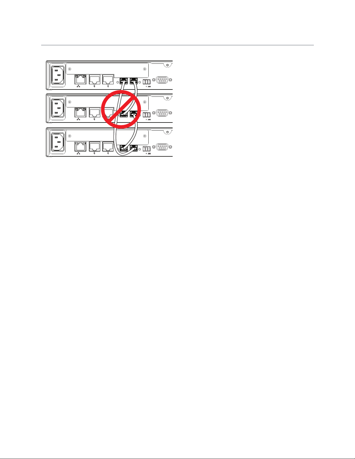
Because the OBAM interface is bi-directional, data will flow in both directions on the single cable between
devices. Due to this bi-directionality, do not loop the OBAM link connections (as follows).
Polycom, Inc. 18
90-250 VAC
50/60 Hz
PIN 2: TXD
PIN 3: RXD
PIN 5: GROUND
PIN 7: CTS
PIN 8: RTS
LAN
C-LINK2
OBAM IR
RS-232
IN OUT
12V
90-250 VAC
50/60 Hz
PIN 2: TXD
PIN 3: RXD
PIN 5: GROUND
PIN 7: CTS
PIN 8: RTS
LAN
C-LINK2
OBAM IR
RS-232
IN OUT
12V
90-250 VAC
50/60 Hz
PIN 2: TXD
PIN 3: RXD
PIN 5: GROUND
PIN 7: CTS
PIN 8: RTS
LAN
C-LINK2
OBAM IR
RS-232
IN OUT
12V
Hardware Installation Guide for the Polycom SoundStructure
Once the devices are connected over OBAM, the SoundStructure devices will behave as one large audio
device, in other words, all the inputs from all the SoundStructure devices are available on all the devices.
Any combination of SoundStructure C16, C12, C8, and SR12 devices may be linked together up to a total
of eight devices.
When the SoundStructure devices are connected over the OBAM Link, the OBAM Input Status LED
illuminates when there is a valid connection between the OBAM IN port on this device and an OBAM OUT
port on a second SoundStructure device. This LED will not illuminate unless there is a valid connection
between the two devices. The OBAM Output Status LED illuminates when there is a valid connection
between the OBAM OUT port on this device and an OBAM IN port on a different SoundStructure device.
This LED will not illuminate unless there is a valid connection between the two devices.
A 18-inch OBAM cable (2457-23574-002) is provided with each SoundStructure device. For longer
distances, we recommend our 40 ft (12 m) cable (2200-34229-002). See the section OBAM Link for more
details. An OBAM link cable may be tested by inserting the same cable into the OBAM IN and OBAM OUT
ports. If the OBAM input and output status LEDs illuminate, the OBAM cable is fully functional.
Device IDs
When multiple devices are connected via the OBAM interface, internal SoundStructure device IDs are
assigned automatically based on the OBAM connections. The device that has no OBAM IN connection will
be device 1. The device connected to that unit will be device 2, and so on until the last device - the device
with no OBAM OUT connection. The device ID is important for ensuring that the devices are sequenced
properly so that the hardware matches the configuration that will be uploaded to the system.
Polycom, Inc. 19

PIN 2: TXD
PIN 3: RXD
PIN 5: GROUND
PIN 7: CTS
PIN 8: RTS
LAN
C-LINK2
OBAM
IR
RS-232
REMOTE CONTROL 2
REMOTE CONTROL 1
IN OUT
1 2 3 4 5 6 7 8
1 2 3 4 5 6 7 8
OUTPUTS
INPUTS
SoundStructure C8
®
12V
PIN 2: TXD
PIN 3: RXD
PIN 5: GROUND
PIN 7: CTS
PIN 8: RTS
LAN
C-LINK2
OBAM
IR
RS-232
REMOTE CONTROL 2
REMOTE CONTROL 1
IN OUT
1 2 3 4 5 6 7 8 9 10 11 12
1 2 3 4 5 6 7 8 9 10 11 12
OUTPUTS
INPUTS
SoundStructure C12
®
12V
PHONE LINE
Hardware Installation Guide for the Polycom SoundStructure
As an example, consider the following figure that shows a SoundStructure C12 linked with a C8.
SoundStructure C12 linked to a SoundStructure C8
The SoundStructure Studio software can be used to create a design that will be uploaded into the devices.
In this example, the configuration file requires devices to be linked together with the C12 as the first device
(device ID 1) and the C8 as the second device (device ID 2). The wiring report summarizes the cabling
connections for the input and output signals. A typical wiring report generated for the SoundStructure
devices is shown in the following text.
This wiring report shows the signal connections to both the SoundStructure C12 at device ID 1, and the
SoundStructure C8 at device ID 2. The report also indicates a telephony interface is plugged into the C12
and a Polycom HDX video codec is connected via the C-Link2 interface to the C12. This report also
summarizes how the individual inputs and outputs should be connected to the rear-panel of the
SoundStructure devices, for instance Table Mic 1 should be connected to input 1 on the SoundStructure
C12.
SoundStructure system: SoundStructure System
C12 (bus id: 1)
C-Series Mic Input
1: Lectern Mic
2: Table Mic 1
3: Table Mic 2
4: Table Mic 3
5: Table Mic 4
6: Table Mic 5
7: Table Mic 6
8: Table Mic 7
9: Table Mic 8
10: Table Mic 9
11: Table Mic 10
12: Table Mic 11
C-Series Line Output
1: Amplifier (Left)
2: Amplifier (Right)
Plugin Card: Single Line Telephone
1: Phone In, Phone Out
C-Link2 Interface: Polycom HDX
Polycom, Inc. 20

1
2
3
Top Vi ew
Hardware Installation Guide for the Polycom SoundStructure
C8 (bus id: 2)
C-Series Mic Input
1: Table Mic 12
2: Table Mic 13
3: Table Mic 14
4: Table Mic 15
5: Table Mic 16
6: Wireless Mic
7: Program Audio (Left)
8: Program Audio (Right)
Wiring the system as described in the wiring report and linking multiple devices as indicated to ensure the
device ID’s of the system match the configuration file is an important step to having the system operate
properly once the configuration file is uploaded to the devices.
Connecting IR Port to Optional Receiver and RS-232 to Control System
IR Port
The IR receiver port is compatible with IR receivers such as Xantech models 780-80, 780-90, 480-00,
480-80, and 490-00. Terminate the IR receiver into the supplied terminal block using the pinout shown in
the following figure. See Chapter 3 of the SoundStructure Design Guide and the software release notes for
additional information on how to use the IR receiver port.
Pin Signal
1+12 V
2Ground
3 IR Signal Data
Polycom, Inc. 21
480-00 Series
Data
+12V
GND
1
2
3
Pin 1Pin 5
Pin 9 Pin 6
Hardware Installation Guide for the Polycom SoundStructure
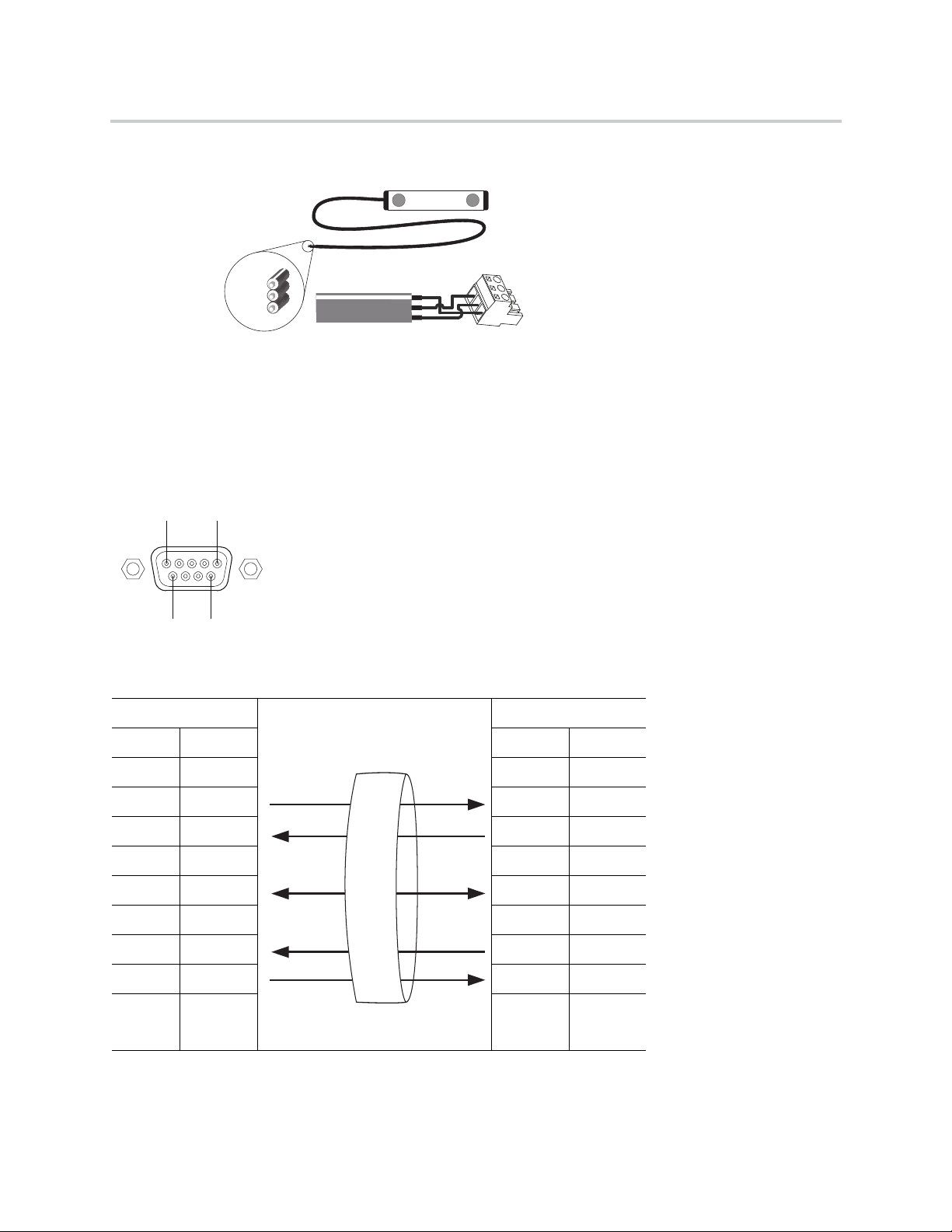
RS-232
The RS-232 interface is capable of running up to 115,200 bps and has a default rate of 9,600 bps, eight data
bits, no parity, one stop bit (8-N-1). The pinout of the connection and the recommended straight-through
cabling to a control system is shown in the following figure.
SoundStructure Control System
Pin Signal Pin Signal
1- 1 -
2TX 2 RX
3RX 3 TX
4- 4 -
5 Ground 5 Ground
6- 6 -
7CTS 7 RTS
8RTS 8 CTS
9- 9 -
Polycom, Inc. 22

T
S
TTS
STS
T
S
T
S
TTS
S
RT
T
R
S
S
12
3
XLR Female
XLR Male
21
3
Balanced Audio Connections
Unbalanced Audio Connections
Hardware Installation Guide for the Polycom SoundStructure
At rates at or above 38,400 bps, it is recommended that flow control be enabled on the control system.
The maximum length of an RS-232 cable is determined by the overall capacitance of the cable. For practical
purposes, the length of the RS-232 cable should not exceed fifty feet.
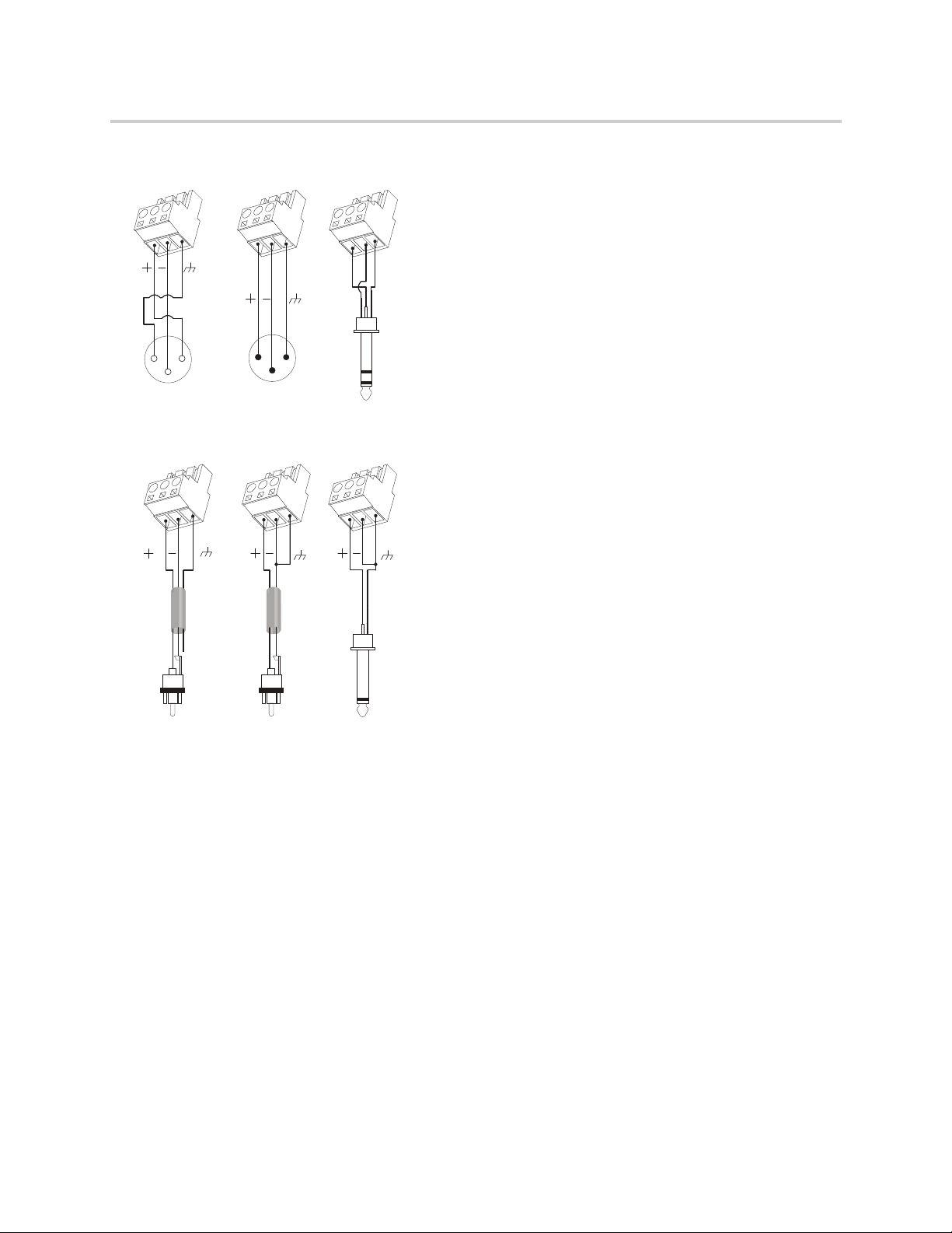
Making Audio Connections
SoundStructure devices provide balanced audio input and output connections that are terminated with 3.5
mm terminal blocks. For each balanced analog input or output on the SoundStructure rear-panel, the first
pin should be connected to the positive signal, the second pin is connected to the negative signal, and the
third pin is chassis ground as shown in the balanced audio connections in the following figure. To connect
the SoundStructure device's audio input and output to unbalanced audio equipment, follow the wiring in the
unbalanced audio connections below.
Balanced and Unbalanced Audio Connectors
When using unbalanced audio sources or audio destinations connected to SoundStructure devices, either
wiring techniques shown previously for connecting RCA jacks to terminal blocks may be used and both will
result in the same voltage level at the tip of the RCA jack.
Polycom, Inc. 23
REMOTE CONTROL 2
REMOTE CONTROL 1
Pin 25 Pin 14
Pin 1
Pin 13
Pin 1
Pin 13
Pin 25 Pin 14
Hardware Installation Guide for the Polycom SoundStructure
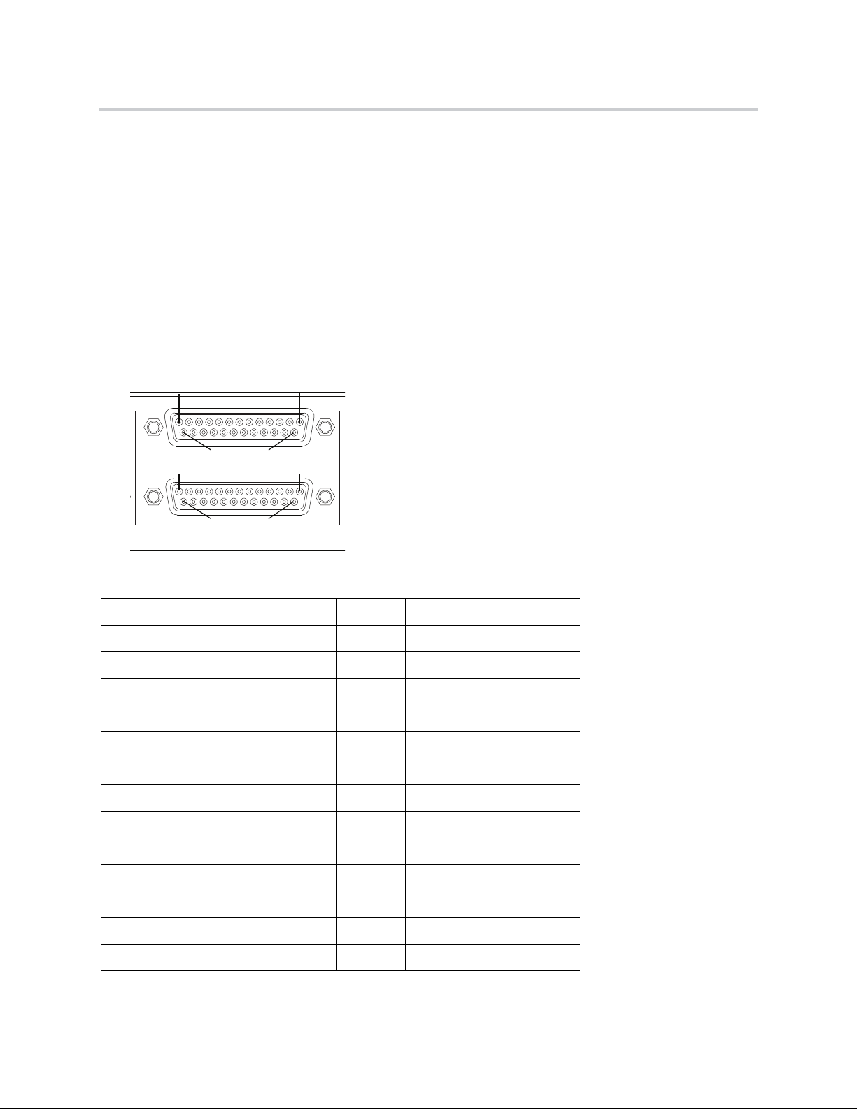
Connecting Logic Ports
There are two logic ports, called Remote Control 1 and Remote Control 2, on the rear-panel of each
SoundStructure device. Please check the software release notes and Chapter 3 of the SoundStructure
Design Manual for information concerning logic pin functionality.
Each Remote Control connector includes eleven logic inputs, eleven logic outputs, an analog gain control
input, a +5 V supply capable of providing up to 500 mA, and a logic ground. Internal to the SoundStructure
device is a fuse that will trigger if the current draw on Pin 1 exceeds 500 mA. The fuse will reset itself once
the excessive load is removed.
As there are two logic connectors, there are a total of twenty-two logic inputs, twenty-two logic outputs, two
analog gain inputs, and two +5 V supplies and two logic grounds per SoundStructure device. The pinouts
and signal definition are shown in the following figures.
Pinouts and Signal Definition
Remote Control 1
Pin Signal Pin Signal
1 +5 V 14 Logic Input 1
2 Logic Output 1 15 Logic Input 2
3 Logic Output 2 16 Logic Input 3
4 Logic Output 3 17 Logic Input 4
5 Logic Output 4 18 Logic Input 5
6 Logic Output 5 19 Logic Input 6
7 Logic Output 6 20 Logic Input 7
8 Logic Output 7 21 Logic Input 8
9 Logic Output 8 22 Logic Input 9
10 Logic Output 9 23 Logic Input 10
11 Logic Output 10 24 Logic Input 11
12 Logic Output 11 25 Ground
13 Analog Gain 1
Polycom, Inc. 24
Logic
Status
SoundStructure Logic Input
Logic Input Pin
Logic Pin 25 (Ground)
3.3V
Hardware Installation Guide for the Polycom SoundStructure
Remote Control 2
Pin Signal Pin Signal
1 +5 V 14 Logic Input 12
2 Logic Output 12 15 Logic Input 13
3 Logic Output 13 16 Logic Input 14
4 Logic Output 14 17 Logic Input 15
5 Logic Output 15 18 Logic Input 16
6 Logic Output 16 19 Logic Input 17
7 Logic Output 17 20 Logic Input 18
8 Logic Output 18 21 Logic Input 19
9 Logic Output 19 22 Logic Input 20
10 Logic Output 20 23 Logic Input 21
11 Logic Output 21 24 Logic Input 22
12 Logic Output 22 25 Ground
13 Analog Gain 2
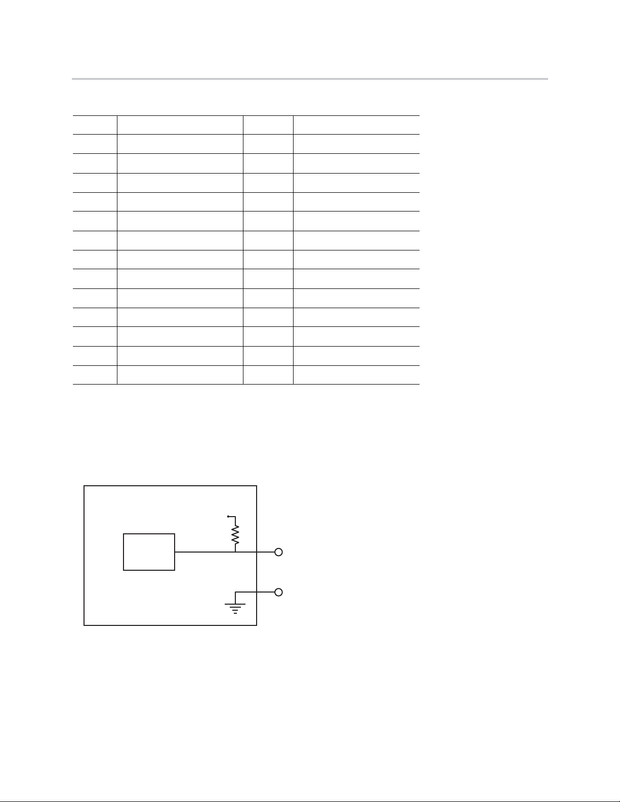
Logic Inputs
All digital logic inputs (logic inputs 1 - 22) operate as contact closures and may either be connected to
ground (closed) or not connected to ground (open). The logic input circuitry is shown in the following figure.
Chapter 4 Logic Examples provides examples of how to use the logic input pins.
Logic Input Circuitry
Analog Gain Input
The analog gain inputs (analog gain 1 and 2) operate by measuring an analog voltage between the analog
input pin and the ground pin. The maximum input voltage level should not exceed +6 V. It is recommended
that the +5 V supply on Pin 1 be used as the upper voltage limit.
Polycom, Inc. 25

Analog
Voltage
Value
SoundStructure Logic Input
Analog Gain Input Pin
Logic Pin 25 (Ground)
Logic Pin 1 (+5V)
5V
Logic
Controller
SoundStructure Logic Output
Logic Output Pin
Chassis
Ground
Hardware Installation Guide for the Polycom SoundStructure
The following figure shows the analog gain input pin and the associated +5 V and ground pins that are used
with the analog gain input pin. The analog voltage on the analog gain input pin is converted to a digital value
via an 8-bit analog-to-digital converter for use within the SoundStructure devices. The maximum voltage
value, i.e., 0 dBFS on the analog gain input, is 4.096 V. 0 V is converted to 0 and 4.096 V and above is
converted to 255.
The chapter Logic Examples provides an example of how to use the analog gain input pin.
Analog Gain Input Pin and +5V and Ground Pins
Logic Outputs
All logic outputs are configured as open-collector circuits and may be used with external voltage sources.
The maximum voltage that should be used with the logic outputs is 60 V with a maximum current of 500 mA.
Logic Outputs
The open collector design is shown in the following figure and works as a switch as follows: when the logic
output pin is set high (on), the transistor will turn on and the signal connected to the logic output pin will be
grounded and current will flow from the logic output pin to chassis ground.
Polycom, Inc. 26

Logic Output = 0
Low (Off)
Logic Output = 1
High (On)
Chassis GroundChassis Ground
Logic Output PinLogic Output Pin
Power cord not plugged inPower cord plugged in
Hardware Installation Guide for the Polycom SoundStructure
When the logic output is set low (off), the transistor will turn off and an open circuit will be created between
the logic output and the chassis ground preventing any flow of current, as shown in the following figure.
Logic Output and Chassis Ground Preventing Current Flow
See Logic Examples for information on how to wire the logic interface for common logic applications.
Powering the System
Connect the AC power line to a grounded AC power main when ready to power the device and plug the
other end securely into the rear of the SoundStructure unit. Ensure the plug is securely inserted as shown
in the following figure. Upon insertion there will be some initial resistance - continue pushing until the power
cord is plugged in.
The SoundStructure units require an AC voltage supply in the range of 90-250 VAC and 50-60 Hz. Power
should be applied after any plug-in cards are installed.
As there is no power switch on the SoundStructure devices, once power is connected, the system will begin
the boot-up process.
For more information, see Front-Panel LED Interpretation.
Configuring the SoundStructure Devices
For information on configuring software for the SoundStructure, see the manual entitled Design Guide for
the Polycom SoundStructure C16, C12, C8, and SR12.
Polycom, Inc. 27

Specifications
Technical Specifications
Dimensions
● 19" (483 mm) W x 13.5" (343 mm) L x 1.75" (45 mm) H (one rack unit)
Weight
● 12 lbs. (5.5 kg) dry, 14 lbs. (6.4 kg) shipping
Connectors
● RS-232: DB9F
● OBAM In/Out: IEEE 1394B
● CLINK2: RJ45
● LAN: RJ45
● Control/Status: DB25F
● Audio: Mini (3.5 mm) quick connect terminal blocks
● IR Receive: Mini (3.5 mm) quick connect terminal block
Power
● Internal power supply
● Input voltage of 100-240 VAC; 50-60 Hz
● Line power requirements (including 0.6 PF): 130 VA (C16), 115 VA (C12), 105 VA (SR12), 95 VA (C8)
Thermal
● Thermal Dissipation (Btu/hr): 266 Btu/hr (C16), 230 Btu/hr (C12), 215 Btu/hr (SR12), 200 Btu/hr (C8)
● Operating temperature 0 - 40° C (104° F)
Operating temperature ranges for the three thermal sensors located on the SoundStructure device are
shown in the following table. These sensor values are found on the Wiring page within SoundStructure
Studio when connected to a SoundStructure device. Green indicates normal operation up to the
temperatures listed in the following table. Yellow indicates an elevated temperature that is acceptable but
the ambient temperature and airflow in the system should be checked. Red indicates an over-temperature
event that must be corrected for proper operation of the SoundStructure device.
Polycom, Inc. 28

Hardware Installation Guide for the Polycom SoundStructure
Thermal Sensors’ Operating Temperature Ranges
Sensor Normal (Green) Warning (Yellow) Error (Red)
150
269° C 79° C 80+° C
353° C 58° C 59+° C
° C 59° C 60+ ° C
Inputs
● Phantom power: 48 V DC through 6.8 kOhm series resistor per leg, 7.5 mA per audio channel,
software selectable
● Analog input gain: -20 to 64 dB on all inputs in 0.5 dB steps, software adjustable
● Maximum input amplitude: +20.4 dBu, 1% THD + N
● Nominal level: 0 dBu (0.775 Vrms)
● Equivalent input noise: <-122 dBu, 20-20,000 Hz, Rs=150 Ohms (1%)
● Input impedance: 10 kOhms
● Input EMI Filter: Pi filter on all audio inputs
Outputs
● Output gain: -100 to 20 dB in 1 dB steps, software adjustable
● Maximum output amplitude: +23 dBu, 1% THD + N
● Nominal output level: 0 dBu (0.775 Vrms)
● Output impedance: 50 Ohm, each leg to ground, designed to drive loads > 600 Ohms
● Output EMI filter: Pi filter on all audio outputs
System
Valid values for all channels
Unless noted, all values are valid for all channels at 0 dB input gain.
Warnin g
● Frequency response: 20-22,000 Hz, + 0.1 /- 0.3 dB
● Idle channel noise: <-109 dB FS no weighting, 20-20,000 Hz, -60dB FS, 997 Hz input signal, 0 dB
gain
● Dynamic range: >109 dB FS no weighting, 20 - 20,000 Hz, -60 dB FS, 997 Hz input signal, 0 dB gain
● Linearity: 0 dB FS to -122 dB FS +/- 1 dB
● THD+N: < 0.005%, -20 dB FS input signal
● Common mode rejection ratio: <-61 dB, 20-20,000 Hz, no weighting
● Cross talk: <-110 dB, 20-20,000 Hz, 1kHz, channel-to-channel
● Latency: Mic/Line inputs to outputs: 20 ms, AEC and NC processing enabled
● Acoustic echo cancellation span: 260 ms
Polycom, Inc. 29

Hardware Installation Guide for the Polycom SoundStructure
● Total cancellation: >65 dB
● Convergence rate: 40 dB/second
● Noise cancellation: 0-20 dB, software selectable
● Control inputs: contact closure
● Status outputs: open collector 60 V and 500 mA maximum total per outputs
● All signal ground pins connected to chassis ground through low impedance planes
Telco
● Input gain: -100 to +20 dB in 1 dB steps, software adjustable
● Nominal transmit level: 0 dBu in SoundStructure device yields -15 to -17 dBm to phone (country code
dependent)
● Off hook loop current: 10 mA (minimum) to 120 mA (maximum)
● Output gain: -100 to +20 dB in 1 dB steps, software adjustable
● Frequency response: 250-3300 Hz
● Dynamic range: >70 dB FS, 250-3300 Hz, "A" weighted
Pin Out Summary
Drawings and part numbers are provided for reference only
Other than cables provided by Polycom, Polycom claims no responsibility or liability
Warnin g
Conference Link2
To build a custom Conference Link2 cable, use shielded CAT5e, or better, and terminate both end
connectors, P1 and P2, with standard 8P8C plugs (for example, RJ45) using the wiring connections shown
in the following figure. The maximum length for this cable is 100 feet (30 m). Note that this cable provides
a cross-over connection between pins 1 and 2 and pins 5 and 6.
for the quality, performance, or reliability of cables based on these reference
drawings. Contact a Polycom reseller to order cables that meet the appropriate
manufacturing tolerances, quality, and performance parameters for particular
applications.
Polycom, Inc. 30

P1
1
2
5
6
7
8
3
SHELL
AWG
24
24
24
24
24
24
24
COLOR
WHITE/GREEN
GREEN
WHITE/ORANGE
ORANGE
WHITE/BROWN
BROWN
DRAIN WIRE
SHIELD
P2
5
6
1
2
7
8
3
SHELL
8
1
1
8
P1 P2
Hardware Installation Guide for the Polycom SoundStructure
Conference Link2 Wiring Connections
P1 - RJ-45 shielded Keystone jack, L-com RJ110C5-S or equivalent,
or
P1 - RJ-45 shielded plug, Tyco 5-569552 or equivalent with shielded RJ-45 panel coupler kit (L-com ECF504-SC5E or
equivalent).
P2- RJ-45 shielded plug, Tyco 5-569552 or equivalent.
OBAM Link
The OBAM cable is a standard 1394b BETA style cable. The 18 in cable (2457-23574-002) ships with the
SoundStructure device. For longer distances, you can purchase our 40 ft (12 m) cable (2200-34229-002).
While OBAM Link uses 1394b cables, the underlying bus protocol is not IEEE1394b compliant which means
that external IEE1394b devices will not be compatible with OBAM Link. Using IEE1394b hubs or repeaters
will not extend the length of OBAM and any non-SoundStructure approved device that is placed on the
OBAM Link will prevent OBAM Link from operating properly.
OBAM Cable
OBAM Port
Polycom, Inc. 31

Black
Red
Green
Blue
Orange
White
PIN 2: TXD
PIN 3: RXD
PIN 5: GRO
PIN 7: CTS
PIN 8: RTS
IR
OUT
12V
1
2
3
Top Vi ew
Hardware Installation Guide for the Polycom SoundStructure
Connector Pinout
1394b
BETA Plug
13
24
95
31
42
59
66
88
SHELL SHELL
Connector pinouts
Pin 7 is not connected.
Warnin g
IR Receiver
1394b
BETA Plug
The IR receiver port on the rear-panel of a SoundStructure device is shown in the following figure.
IR Receiver Port
The IR receiver port accepts a standard 3.5 mm terminal block which should be terminated to the IR receiver
as shown in the following figures.
Polycom, Inc. 32

Pin 1Pin 5
Pin 9 Pin 6
Hardware Installation Guide for the Polycom SoundStructure
Pin Signal
1+12 V
2Ground
3 IR Signal Data
RS-232
The RS-232 interface requires a straight-through cabling to a control system as shown in the following
figures.
SoundStructure Pins
SoundStructure Pin and Signal Control System
SoundStructure Control System
Pin Signal Pin Signal
1- 1 -
2TX 2 RX
3RX 3 TX
4- 4 -
5 Ground 5 Ground
6- 6 -
7CTS 7 RTS
8RTS 8 CTS
9- 9 -
Polycom, Inc. 33

REMOTE CONTROL 2
REMOTE CONTROL 1
Pin 25 Pin 14
Pin 1
Pin 13
Pin 1
Pin 13
Pin 25 Pin 14
Hardware Installation Guide for the Polycom SoundStructure
Logic Interface
Remote Controls 1 and 2
Remote Control 1
Pin Signal Pin Signal
1 +5 V 14 Logic Input 1
2 Logic Output 1 15 Logic Input 2
3 Logic Output 2 16 Logic Input 3
4 Logic Output 3 17 Logic Input 4
5 Logic Output 4 18 Logic Input 5
6 Logic Output 5 19 Logic Input 6
7 Logic Output 6 20 Logic Input 7
8 Logic Output 7 21 Logic Input 8
9 Logic Output 8 22 Logic Input 9
10 Logic Output 9 23 Logic Input 10
11 Logic Output 10 24 Logic Input 11
12 Logic Output 11 25 Ground
13 Analog Gain 1
Remote Control 2
Pin Signal Pin Signal
1 +5 V 14 Logic Input 12
2 Logic Output 12 15 Logic Input 13
3 Logic Output 13 16 Logic Input 14
4 Logic Output 14 17 Logic Input 15
5 Logic Output 15 18 Logic Input 16
Polycom, Inc. 34

Hardware Installation Guide for the Polycom SoundStructure
Remote Control 2
6 Logic Output 16 19 Logic Input 17
7 Logic Output 17 20 Logic Input 18
8 Logic Output 18 21 Logic Input 19
9 Logic Output 19 22 Logic Input 20
10 Logic Output 20 23 Logic Input 21
11 Logic Output 21 24 Logic Input 22
12 Logic Output 22 25 Ground
13 Analog Gain 2
Audio Connections
SoundStructure devices provide balanced audio input and output connections that are terminated with 3.5
mm terminal blocks as shown in the following figure.
3.5 MM Terminal Block
1
For each balanced analog input or output on the SoundStructure rear-panel, the first pin should be
connected to the positive signal, the second pin is connected to the negative signal, and the third pin is
chassis ground as shown in the balanced audio connections in the following figure. To connect the
SoundStructure device's audio input and output to other balanced or unbalanced audio equipment, follow
the wiring convention in the unbalanced audio connections following figure.
Polycom, Inc. 35
T
S
TTS
STS
T
S
T
S
TTS
S
RT
T
R
S
S
12
3
XLR Female
XLR Male
21
3
Balanced Audio Connections
Unbalanced Audio Connections
Hardware Installation Guide for the Polycom SoundStructure
Balanced and Unbalanced Audio Connections
Polycom, Inc. 36
Remote Control
Pin 14 : Logic Input 1
Pin 25 : Ground
Logic Examples
Logic Input
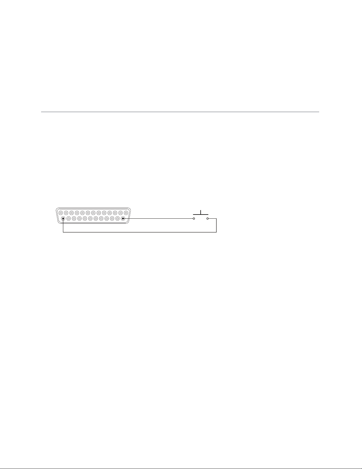
Contact Closure
When the contact is closed, the logic input pin (Pin 14 in the example below) is driven low (0 or off). When
the switch is open, the logic input pin will float high (1 or on).
Typical applications may be push to mute or push to talk buttons or room combining for changing the device
settings based on the room configuration.
Contact Closure
Logic Output
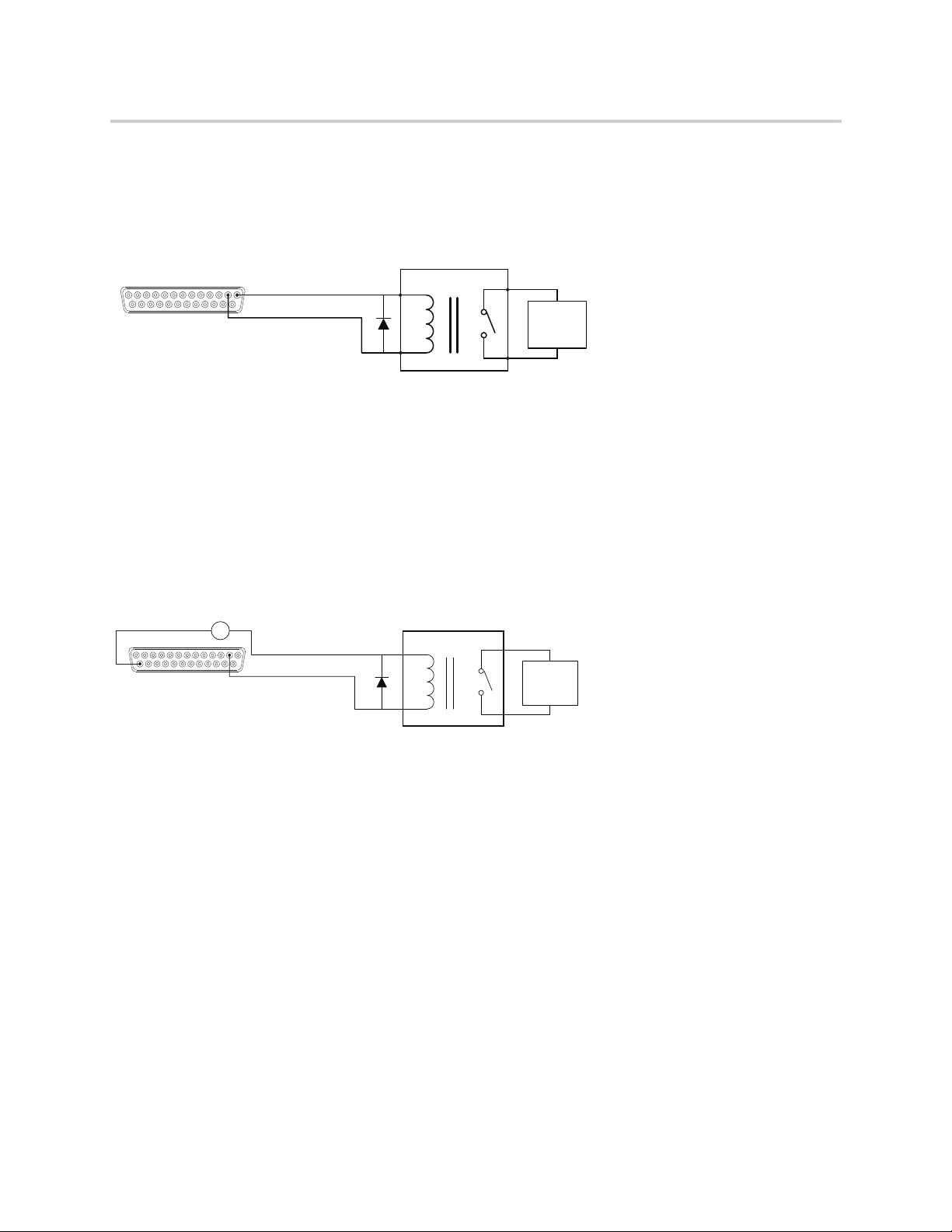
SoundStructure Powered Relay
Relays rated for +5 V or lower may be driven directly from the +5 V logic connector pin 1 supply. Relays
rated for more than +5 V will need an external power supply as described in the next example.
When the logic output (Pin 2 in this example) is set on (1 or high), current flows from Pin 2 to ground and
current that flows will energize the relay coil and close the relay contact. When the logic output is set off (0
or low), current will stop flowing to the relay coil, causing the relay contact to open. A diode is recommended
to be placed in parallel with the relay to provide a path for the discharge current of the magnetic coil of the
relay. This current will discharge over a very short period of time and a diode capable of handling a large
amount of surge current such as the 1N4001 is recommended and is available from several manufacturers.
Polycom, Inc. 37
Exter nal
Device to
be
Controlled
5 V Relay
Pin 1 : +5 V
Pin 2 : Logic Output 1
Exter nal
Device to
be
Controlled
12 V Relay
Remote Control
Pin 25 : Ground
External +12 V
Pin 2 : Logic Output 1
- +
Hardware Installation Guide for the Polycom SoundStructure
This example circuit uses an Omron G5CA relay and the coil resistance is 125 ohms. Because of this coil
resistance, an additional series resistor is not required to limit the current from the 5 V supply to less than
500 mA in this example.
SoundStructure Powered Relay
Externally Powered Relay
SoundStructure can be used with externally powered relays when the following conditions exist:
● The relay is DC powered.
● The DC voltage does not exceed 60 V.
● The current from the power supply and relay circuit does not exceed 500 mA.
Externally Powered Relay
As with the 5 V relay example, when the logic output pin (Pin 2 in the above example) is set on (1 or high),
the relay energizes and the relay contact is closed. When the logic output in is set off (0 or low), current
stops flowing, and the relay de-energizes and the relay contact is opened.
A diode is recommended to be placed in parallel with the relay to provide a path for the discharge of the
magnetic coil of the relay. This current will discharge over a very short period of time and a diode capable
of handling a large amount of surge current such as the 1N4001 is recommended and is available from
several manufacturers. The 1N4001 is rated up to 50 V, if higher voltages are required, the 1N4002 is rated
to 100 V.
This circuit uses an Omron G7L 12 V relay with a coil resistance of 75 ohms. For this reason, an additional
series resistor between the power supply and relay is not needed to ensure the current from the 5 V supply
is less than 500 mA.
The ground connection of the power supply must be connected to the ground pin of the logic connector (Pin
25) in order for the return currents from the external power supply to be able to return to their source.
Polycom, Inc. 38

LED
Remote Control
Pin 1 : +5V
Pin 2 : Logic Output 1
274 ohm
Hardware Installation Guide for the Polycom SoundStructure
Driving an LED
SoundStructure logic outputs can be used to turn on or off LEDs. In this example when the logic output is
driven on (1 or high), current will flow, and the LED will turn on. When the logic output is set off (0 or low),
current will stop flowing, and the LED will turn off.
Most standard LEDs need about 2.0 V to illuminate. In this example a 274 ohm resistor is used to limit the
current from Pin 1.
A series resistor must be used to limit the voltage and current to a safe level for the LED.
Increasing the series resistor value will decrease the current through the circuit and will also decrease the
voltage at the input to the LED, reducing the brightness of the LED.
Driving an LED
Logic Input and Output
Push To Talk Microphones
The SoundStructure devices may be used with push to talk microphones such as the Shure MX392.
When the orange (LED in) wire is connected to ground due to the SoundStructure logic output being turned
on, the LED on the microphone will turn on. The LED is powered from the SoundStructure phantom power
supply on the red and black cables. This means that the LED on the microphone does not need external
power through a pull-up resistor on the orange (LED in) wire. The shield of the cable provides a ground for
the entire audio and logic circuit even though there is a separate green wire for Logic Ground. This means
that the green wire does not need to be connected to SoundStructure device. One could connect the green
wire to the shield at the mic side and then only need to run a 4-conductor cable plus shield to the
SoundStructure device, or one could run the microphone's logic ground to the ground on the logic connector.
Polycom, Inc. 39

Remote Control
Analog Input
Pin 2 : Logic Output 1
Pin 25 : Ground
Pin 14 : Logic Input 1
White
Orange
Green
Red
Black
Shield
Remote Control
Pin 1 : +5V
Pin 13 : Analog Input
Pin 25 : Ground
10K ohm
Hardware Installation Guide for the Polycom SoundStructure
No current-limiting resistors are needed between the microphone and the SoundStructure device as the
current on the Orange (LED IN) wire when the LED is on is on the order of microamps.
Push to Talk Microphone
Analog Gain Control
Pin 13 on each Remote control connector may be used with an analog potentiometer to provide an analog
input signal that can be used to control volume or other settings within SoundStructure devices.
Analog Gain Control
o
Polycom, Inc. 40

PHONE LINE
LINE 2 LINE 1
Accessories
The SoundStructure product family includes the following accessories, which can be purchased separately.
See the SoundStructure Accessory Guide on Polycom Voice Support for an up to date collection of
SoundStructure product accessories.
Accessory Accessory Graphic
Single-Line PSTN Interface
2200-35003-001
Dual-Line PTSN interface
2200-35004-001
SoundStructure VoIP Interface
2200-35005-001
Conference Link2 Cable (18")
2457-23574-002
Polycom, Inc. 41

Hardware Installation Guide for the Polycom SoundStructure
Accessory Accessory Graphic
OBAM Cable (40’)
2200-34229-002
Polycom RealPresence Group Series Microphone Array
2215-63885-001
Polycom Microphone Cable Adapter
2457-25646-001
Polycom HDX Microphone Cable 25 ft.
2457-23216-001
Polycom HDX Microphone Cable 15 ft.
2457-23215-001
Polycom Ceiling Microphone Array
2200-23809-001 (Black)
2200-23809-002 (White)
Polycom, Inc. 42

Hardware Installation Guide for the Polycom SoundStructure
Accessory Accessory Graphic
Polycom Ceiling Microphone Extension Kit
2200-23810-001 (Black)
2200-23810-002 (White)
Terminal Blocks
2215-80031-001
Audio Adapter Cable
2457-23492-001
Polycom, Inc. 43

Regulatory Notices And Warranty Information
Regulatory Notices
USA And Canada
Pt 15 Rules
This device complies with part 15 of the FCC Rules. Operation is subject to the following two conditions:
This device may not cause harmful interference, and this device must accept any interference received,
including interference that may cause undesired operation.
Class A Digital Device Or Peripheral
NOTE: This equipment has been tested and found to comply with the limits for a Class A digital device,
pursuant to part 15 of the FCC Rules. These limits are designed to provide reasonable protection against
harmful interference when the equipment is operated in a commercial environment. This equipment
generates, uses, and can radiate radio frequency energy and, if not installed and used in accordance with
the instruction manual, may cause harmful interference to radio communications. Operation of this
equipment in a residential area is likely to cause harmful interference in which case the user will be required
to correct the interference at his own expense.
Modifications
In accordance with part 15 of the FCC rules, the user is cautioned that any changes or modifications not
expressly approved by Polycom Inc. could void the user’s authority to operate the equipment.
Exhibit J - Customer Information
This equipment complies with Part 68 of the FCC rules and the requirements adopted by the ACTA. On the
exterior of the cabinet of this equipment is a label that contains, among other information, a product identifier
in the format 2HWTE01BSSTRUCTURE. If requested, this number must be provided to the telephone
company.
● ACTA Registration Number: 2HWTE01BSSTRUCT
● Ringer Equivalence Number (REN): 0.1B
●
Facility Interface Code (FIC): 02LS2
●
Service Order Code (SOC): 9.0Y
●
USOC Jack Type: RJ11C
A FCC compliant telephone cord and modular plug is provided with this equipment. This equipment is
designed to be connected to the telephone network or premises wiring using a compatible modular jack that
is Part 68 compliant. See Installation Instructions for details.
Polycom, Inc. 44

Hardware Installation Guide for the Polycom SoundStructure
The REN is used to determine the quantity of devices that may be connected to the telephone line.
Excessive RENs on the telephone line may result in the devices not ringing in response to an incoming call.
Typically, the sum of RENs should not exceed five (5.0). To be certain of the number of devices that may be
connected to a line (as determined by the total RENs) contact the local telephone company.
If this equipment Polycom SoundStructure TEL 1 and SoundStructure TEL 2 causes harm to the telephone
network, the telephone company will notify you in advance that temporary discontinuance of service may
be required. But if advance notice isn't practical, the telephone company will notify the customer as soon as
possible. Also, you will be advised of your right to file a complaint with the FCC if you believe it is necessary.
The telephone company may make changes to its facilities, equipment, operations or procedures that could
affect the operation of the equipment. If this happens the telephone company will provide advance notice
so you can make the necessary modifications to maintain uninterrupted service.
If trouble is experienced with this equipment Polycom SoundStructure TEL 1 and SoundStructure TEL 2, for
repair or warranty information, please contact Polycom Inc., 4750 Willow Road, Pleasanton, CA
94588-2708 USA 408.526.9000. If the equipment is causing harm to the telephone network, the telephone
company may request that you disconnect the equipment until the problem is resolved.
Connection to party line service is subject to state tariffs. (Contact the state public utility commission, public
service commission or corporation commission for information.)
Data Equipment
The table below shows which jacks are associated with which modes of operation:
Mode of Operation USOC Jack
Permissive RJ11C
Automatic Dialing
WHEN PROGRAMMING EMERGENCY NUMBERS AND/OR MAKING TEST CALLS TO EMERGENCY
NUMBERS;
● Remain on the line and briefly explain to the dispatcher the reason for the call.
● Perform such activities in the off-peak hours, such as early morning or late evening.
Canada
Canadian EMC Class A
English Statement:
This Class [A] digital apparatus complies with Canadian ICES-003.
French Statement:
Cet appareil numérique de la classe [A] est conforme à la norme NMB-003 du Canada.
This product meets the applicable Industry Canada technical specifications.
The Ringer Equivalence Number (REN) assigned to each relevant terminal device provides an indication
of the maximum number of terminals allowed to be connected to a telephone interface. The termination on
Polycom, Inc. 45

Hardware Installation Guide for the Polycom SoundStructure
an interface may consist of any combination of devices subject only to the requirement that the sum of the
Ringer Equivalence Numbers of all the devices does not exceed 5.
The REN of this equipment is either marked on the unit or included in the new style USA (FCC registration
number). In the case that the REN is included in the FCC number the user should use the flowing key to
determine the value:
The FCC number is formatted as US: AAAEQ##TXXX.
## is the Ringer Equivalence Number without a decimal point (e.g. REN of 1.0 = 10, REN of 0.3 = 03). In
the case of a “Z” ringer, ZZ shall appear. In the case of approved equipment without a network interface and
equipment not connecting to circuits with analog ringing supplied then “NA” shall appear.
EEA (European Economic Area) Including Switzerland
CE Mark
This SoundStructure has been marked with the CE mark. This mark indicates compliance with with all
applicable CE marking directives. A full copy of the EU declaration of conformity can be obtained from
Polycom (Netherlands) BV, Orlyplein 10, 23rd Floor 1043DP, Amsterdam, Netherlands.
Australia
Mains powered POT’s Voice Telephony without Emergency 000 dialing
Warning:
This equipment will be inoperable when mains power fails.
Reference: AS/ACIF S002:2001 (incorporating Amdt 1) DECEMBER 2001
Clause 5.1.8.4 Provision of power-fail advice
Japan (VCCI)
Polycom, Inc. 46

Hardware Installation Guide for the Polycom SoundStructure
Korea
Class A
New Zealand
General Warning:
The grant of a Telepermit for any item of terminal equipment indicates only that Telecom has accepted that
the item complies with minimum conditions for connection to its network. It indicates no endorsement of the
product by Telecom, nor does it provide any sort of warranty. Above all, it provides no assurance that any
item will work correctly in all respects with another item of Telepermitted equipment of a different make or
model, nor does it imply that any product is compatible with all of Telecom’s network services.
Important Notice:
Under power failure conditions, this telephone may not operate. Please ensure that a separate telephone,
not dependent on local power, is available for emergency use.
Russia
The manufacture of this product is Polycom USA.
6001 America Center Drive
San Jose, CA 95002
USA
enquiries@polycom.com
+1 925 924 6000
Polycom LLC is the authorized representative.
Polycom (Russia)
Paveletskaya Square
Bld.2, Block 2, 23rd Floor
Business Center "Paveletskaya Plaza"
Moscow
Tel: +7 495 213 1237
alexey.gorbunov@polycom.com
Polycom, Inc. 47

Hardware Installation Guide for the Polycom SoundStructure
EMC Class A Device:
The SoundStructure C Series and SR Class A products, which meet standards for use in business, industrial
and commercial settings, are not intended to be used in residential environments.
Safety Considerations for Storage and Transportation
● SoundStructure products have a 7 year period of life.
● SoundStructure products have a 7 year period of storage.
● SoundStructure products have a -30C to 60C/ 35 ~90% RH non-condensing at 40C storage
requirement.
● SoundStructure products have a -30C to 60C/ 35 ~90% RH non-condensing at 40C transportation
requirement.
Recycling
End of Life Products
Polycom encourages you to recycle your end-of-life Polycom products in an environmentally considerate
way. In accordance with the requirements of the European Waste Electronic and Electrical Equipment
(WEEE) Directive, all Polycom products are marked with the crossed wheelie bin symbol. Products that
carry this symbol should be not be disposed of in the household or general waste stream. Detail of the
options open to you and the guidance on the requirements for the recycling and environmentally considerate
disposal of your end of life. Polycom products can be found at
http://www.polycom.com/WEEE.
Documentation
Polycom, Inc. has a right to change the Polycom SoundStructure Hardware Installation Guide without prior
notification.
Troubleshooting
This section provides information about actions required if the product does not work correctly.
● To search for answers in product documentation, see Search for Answers in the Product
Documentation.
● To use the Knowledge Base, see Use the Knowledge Base.
● To access Polycom Technical Support, see Access Polycom Technical Support.
Additional information, user guides, and software updates are available at support.polycom.com.
Search for Answers in the Product Documentation
You can find Polycom product documentation at support.polycom.com. Under Documents and Downloads,
select Voice > SoundStructure, and search for the document you want. For Troubleshooting tips, see the
Troubleshooting chapter in the Polycom SoundStructure Design Guide.
Use the Knowledge Base
For more troubleshooting information, search the Knowledge Base at Polycom Support.
Polycom, Inc. 48

Hardware Installation Guide for the Polycom SoundStructure
Access Polycom Technical Support
If you are not able to make test calls successfully and you have verified that the equipment is installed and
set up correctly, contact your Polycom distributor or Polycom Technical Support. To contact Polycom
Technical Support, go to Polycom Support web site.
Product Manufacturing Information
This section includes manufacturing information for Polycom SoundStructure C8, SoundStructure C12,
SoundStructure C16, and SoundStructure SR12.
Country of Manufacture
The country of manufacture is Thailand.
Sales Terms and Conditions
Sales terms and conditions are stated in the agreements with authorized distributors.
Month and Year of Production
The fields YYYYMMDDLL include the month, year, and location of production, and is located on the bottom
of the SoundStructure device with the Serial number. The following table provides a description of each field
for production.
Month and Year Fields
Field Field Description
YYYY Production year. This is the year during which the unit was manufactured.
MM Production month. There are twelve months in a year, therefore these two digits will
line in the range between 01-12.
DD Production day. There are up to thirty one days in a month, therefore these two digits
will lie in the range between 01-31.
LL Location code. This is used to determine the factory where the unit was produced.
South Africa
Important Notice to South African customers:
Polycom recommends the use of an external surge suppressor when using the SoundStructure TEL1 or
TEL2 plug-in cards.
A standard DM surge protector (Telkom license number MIS/19) is available from:
Design Modifications CC
Att: Petrus Geyser
P.O. Box 15245
Sinoville 0129
South Africa
Tel: (082) 452 0269
Polycom, Inc. 49

Hardware Installation Guide for the Polycom SoundStructure
Fax: (012) 711 0872
Taiwan
For connection in Taiwan, Polycom requires the use of external surge protection on the PSTN
telecommunication interfaces connected to the TEL1 and TEL2 cards.
Polycom recommends the APC (American Power Conversion) ProtectNet PTel2 for this purpose. Details
may be found at www.apc.com.
For use with the TEL2 interface card, the PTEL2 device will provide protection for both lines if a cable with
the following pinout is used on both sides of the surge protector:
RJ45 pin 3 and 4 to RJ11 (6 pin) pin 3 and 4
RJ45 pin 5 and 6 to RJ11 (6 pin) pin 3 and 4.
For use with the TEL1 interface card, the PTEL2 device will provide protection for the PSTN line if a cable
with the following pinout is used on both sides of the surge protector:
RJ45 pin 3 and 4 to RJ11 (6 pin) pin 3 and 4.
Properly Connect the Surge Suppressor
The surge suppressor is directional and must be connected in accordance with the
Warnin g
supplied instructions. The connection of the earth lead on the surge suppressor to
an effective earth bonding point is a requirement of its correct operation.
Rest Of World
EMC. CLASS A ITE
WARNING
This is a Class A product. In a domestic environment this product may cause radio interference in which
case the user may be required to take adequate measures.
Installation Instructions
Installation must be performed in accordance with all relevant national wiring rules
Plug acts as Disconnect Device
The socket outlet to which this apparatus is connected must be installed near the equipment and must
always be readily accessible
Warranty Information
LIMITED WARRANTY
Polycom warrants to the end user (“Customer”) that the product will be free from defects in workmanship
and materials, under normal use and service, for one year, or such longer period as Polycom may announce
Polycom, Inc. 50

Hardware Installation Guide for the Polycom SoundStructure
publicly from time to time for particular products, from the date of purchase from Polycom or its authorized
reseller.
Polycom's sole obligation under this express warranty shall be, at Polycom's option and expense, to repair
the defective product or part, deliver to Customer an equivalent product or part to replace the defective item,
or if neither of the two foregoing options is reasonably available, Polycom may, in its sole discretion, refund
to Customer the purchase price paid for the defective product. All products that are replaced will become
the property of Polycom. Replacement products or parts may be new or reconditioned. Polycom warrants
any replaced or repaired product or part for ninety (90) days from shipment, or the remainder of the initial
warranty period, whichever is longer.
Products returned to Polycom must be sent prepaid and packaged appropriately for safe shipment and it is
recommended that they be insured or sent by a method that provides for tracking of the package.
Responsibility for loss or damage does not transfer to Polycom until the returned item is received by
Polycom. The repaired or replaced item will be shipped to Customer, at Polycom's expense, not later than
thirty (30) days after Polycom receives the defective product, and Polycom will retain risk of loss or damage
until the item is delivered to Customer.
EXCLUSIONS. POLYCOM WILL NOT BE LIABLE UNDER THIS LIMITED WARRANTY IF ITS TESTING
AND EXAMINATION DISCLOSE THAT THE ALLEGED DEFECT OR MALFUNCTION IN THE PRODUCT
DOES NOT EXIST OR RESULTS FROM:
● FAILURE TO FOLLOW POLYCOM'S INSTALLATION, OPERATION, OR MAINTENANCE
INSTRUCTIONS.
● UNAUTHORIZED PRODUCT MODIFICATION OR ALTERATION.
● UNAUTHORIZED USE OF COMMON CARRIER COMMUNICATION SERVICES ACCESSED
THROUGH THE PRODUCT.
● ABUSE, MISUSE, NEGLIGENT ACTS OR OMISSIONS OF CUSTOMER AND PERSONS UNDER
CUSTOMER'S CONTROL; OR
● ACTS OF THIRD PARTIES, ACTS OF GOD, ACCIDENT, FIRE, LIGHTING, POWER SURGES OR
OUTAGES, OR OTHER HAZARDS.
WARRANTY EXCLUSIVE. IF A POLYCOM PRODUCT DOES NOT OPERATE AS WARRANTED ABOVE,
CUSTOMER'S SOLE REMEDY FOR BREACH OF THAT WARRANTY SHALL BE REPAIR,
REPLACEMENT, OR REFUND OF THE PURCHASE PRICE PAID, AT POLYCOM'S OPTION. TO THE
FULL EXTENT ALLOWED BY LAW, THE FOREGOING WARRANTIES AND REMEDIES ARE
EXCLUSIVE AND ARE IN LIEU OF ALL OTHER WARRANTIES, TERMS, OR CONDITIONS, EXPRESS
OR IMPLIED, EITHER IN FACT OR BY OPERATION OF LAW, STATUTORY OR OTHERWISE,
INCLUDING WARRANTIES, TERMS, OR CONDITIONS OF MERCHANTABILITY, FITNESS FOR A
PARTICULAR PURPOSE, SATISFACTORY QUALITY, CORRESPONDENCE WITH DESCRIPTION, AND
NON-INFRINGEMENT, ALL OF WHICH ARE EXPRESSLY DISCLAIMED. POLYCOM NEITHER
ASSUMES NOR AUTHORIZES ANY OTHER PERSON TO ASSUME FOR IT ANY OTHER LIABILITY IN
CONNECTION WITH THE SALE, INSTALLATION, MAINTENANCE OR USE OF ITS PRODUCTS.
SUPPORT & SERVICE AGREEMENTS. If you purchased your product from a Polycom Authorized
Reseller, contact the Authorized Reseller for information about support and service agreements applicable
to your product.
For information on Polycom service, go to the Polycom web site www.polycom.com, products and services
menu, or call 1-800-765-9266, outside the US call 1-408-526-9000, or your local Polycom Office, as listed
on the Polycom Web site.
LIMITATION OF LIABILITY. TO THE FULL EXTENT ALLOWED BY LAW, POLYCOM EXCLUDES FOR
ITSELF AND ITS SUPPLIERS ANY LIABILITY, WHETHER BASED IN CONTRACT OR TORT
Polycom, Inc. 51

Hardware Installation Guide for the Polycom SoundStructure
(INCLUDING NEGLIGENCE), FOR INCIDENTAL, CONSEQUENTIAL, INDIRECT, SPECIAL, OR
PUNITIVE DAMAGES OF ANY KIND, OR FOR LOSS OF REVENUE OR PROFITS, LOSS OF BUSINESS,
LOSS OF INFORMATION OR DATA, OR OTHER FINANCIAL LOSS ARISING OUT OF OR IN
CONNECTION WITH THE SALE, INSTALLATION, MAINTENANCE, USE, PERFORMANCE, FAILURE,
OR INTERRUPTION OF ITS PRODUCTS, EVEN IF POLYCOM OR ITS AUTHORIZED RESELLER HAS
BEEN ADVISED OF THE POSSIBILITY OF SUCH DAMAGES, AND LIMITS ITS LIABILITY TO REPAIR,
REPLACEMENT, OR REFUND OF THE PURCHASE
PRICE PAID, AT POLYCOM'S OPTION. THIS DISCLAIMER OF LIABILITY FOR DAMAGES WILL NOT BE
AFFECTED IF ANY REMEDY PROVIDED HEREIN SHALL FAIL OF ITS ESSENTIAL PURPOSE.
DISCLAIMER. Some countries, states, or provinces do not allow the exclusion or limitation of implied
warranties or the limitation of incidental or consequential damages for certain products supplied to
consumers, or the limitation of liability for personal injury, so the above limitations and exclusions may be
limited in their application to you. When the implied warranties are not allowed to be excluded in their
entirety, they will be limited to the duration of the applicable written warranty. This warranty gives you
specific legal rights which may vary depending on local law.
GOVERNING LAW. This Limited Warranty and Limitation of Liability shall be governed by the laws of
the State of California, U.S.A., and by the laws of the United States, excluding their conflicts of laws
principles. The United Nations Convention on Contracts for the International Sale of Goods is hereby
excluded in its entirety from application to this Limited Warranty and Limitation of Liability.
Polycom, Inc. 52
 Loading...