

Poly HDX 7000 Poly HDX Systems Deployment Guide for Maximum Security Environments Version 3.1.9

[Type the document title]
Polycom Document Title 1
3.1.9 | April 2016 | 3725-12748-010A
Military Unique Deployment Guide
Polycom® HDX® Systems Deployment Guide
for Maximum Security Environments

Copyright
language or format, or transmitted in any form or by any means, electronic or mechanical, for any purpose, without the
express written permission of Polycom, Inc.
6001 America Center Drive
San Jose, CA 95002
USA
Trademarks Polycom
trademarks and/or service marks of Polycom, Inc. and are registered and/or common law marks in the United States
and various other countries.
All other trademarks are property of their respective owners. No portion hereof may be reproduced or transmitted in any
form or by any means, for any purpose other than the recipient's personal use, without the express written permission
of Polycom.
©
2016, Polycom, Inc. All rights reserved. No part of this document may be reproduced, translated into another
®
, the Polycom logo and the names and marks associated with Polycom products are
Disclaimer While Polycom uses reasonable efforts to include accurate and up-to-date information in this document,
Polycom makes no warranties or representations as to its accuracy. Polycom assumes no liability or responsibility for
any typographical or other errors or omissions in the content of this document.
Limitation of Liability Polycom and/or its respective suppliers make no representations about the suitability of the
information contained in this document for any purpose. Information is provided "as is" without warranty of any kind and
is subject to change without notice. The entire risk arising out of its use remains with the recipient. In no event shall
Polycom and/or its respective suppliers be liable for any direct, consequential, incidental, special, punitive or other
damages whatsoever (including without limitation, damages for loss of business profits, business interruption, or loss of
business information), even if Polycom has been advised of the possibility of such damages.
End User License Agreement By installing, copying, or otherwise using this product, you acknowledge that you
have read, understand and agree to be bound by the terms and conditions of the End User License Agreement for this
product. The EULA for this product is available on the Polycom Support page for the product.
Patent Information The accompanying product may be protected by one or more U.S. and foreign patents and/or
pending patent applications held by Polycom, Inc.
Open Source Software Used in this Product This product may contain open source software. Y ou may receive
the open source software from Polycom up to three (3) years after the distribution date of the applicable product or
software at a charge not greater than the cost to Polycom of shipping or distributing the software to you. To receive
software information, as well as the open source software code used in this product, contact Polycom by email at
OpenSourceVideo@polycom.com.
Customer Feedback We are striving to improve our documentation quality and we appreciate your feedback. Email
your opinions and comments to DocumentationFeedback@polycom.com.
Polycom Support Visit the Polycom Support Center for End User License Agreements, software downloads,
product documents, product licenses, troubleshooting tips, service requests, and more.
2

Contents
Document Change History . . . . . . . . . . . . . . . . . . . . . . . . . . . . . . . . . . . . 4
FIPS 140-2 Cryptography . . . . . . . . . . . . . . . . . . . . . . . . . . . . . . . . . . . . . 5
Upgrading and Downgrading Your Polycom HDX System . . . . . . . . . . . . 5
Upgrading from Versions Earlier than 2.7.0_J . . . . . . . . . . . . . . . . . . 5
Updating the Software From Version 2.7-Based Releases . . . . . . . . 5
Using the Maximum Security Profile . . . . . . . . . . . . . . . . . . . . . . . . . . . . . 6
Setup Wizard . . . . . . . . . . . . . . . . . . . . . . . . . . . . . . . . . . . . . . . . 6
Security Settings . . . . . . . . . . . . . . . . . . . . . . . . . . . . . . . . . . . . . 7
Password Settings for Room, Remote Access, User Passwords 7
Meeting Password Settings . . . . . . . . . . . . . . . . . . . . . . . . . . . . . 8
Account Management . . . . . . . . . . . . . . . . . . . . . . . . . . . . . . . . . 9
Certificates, Revocation, and Whitelist . . . . . . . . . . . . . . . . . . . . . 9
Remote Access Settings . . . . . . . . . . . . . . . . . . . . . . . . . . . . . . . 9
External Authentication . . . . . . . . . . . . . . . . . . . . . . . . . . . . . . . 10
Other Settings . . . . . . . . . . . . . . . . . . . . . . . . . . . . . . . . . . . . . . 10
Locating Your System . . . . . . . . . . . . . . . . . . . . . . . . . . . . . . . . . . . . . . . 11
Installing in a Non-DHCP Environment . . . . . . . . . . . . . . . . . . . . . . . . . . 11
Install on a Network Using 802.1X . . . . . . . . . . . . . . . . . . . . . . . . . . . . . 11
Configuring Your Local System . . . . . . . . . . . . . . . . . . . . . . . . . . . . . . . . 12
Configuring Your System for Remote Access . . . . . . . . . . . . . . . . . . . . . 16
Configuring Your Room and User Password Policy . . . . . . . . . . . . . . . . 16
Configuring the System to Use Certificates . . . . . . . . . . . . . . . . . . . . . . 17
Detecting Intrusions . . . . . . . . . . . . . . . . . . . . . . . . . . . . . . . . . . . . . . . . 17
Viewing Network Interface and System Status . . . . . . . . . . . . . . . . . . . . 18
Network Interface Status . . . . . . . . . . . . . . . . . . . . . . . . . . . . . . . . . 18
Quad BRI Network Interface Status Lights . . . . . . . . . . . . . . . . . 18
PRI Network Interface Status Lights . . . . . . . . . . . . . . . . . . . . . 19
Viewing System Status . . . . . . . . . . . . . . . . . . . . . . . . . . . . . . . . . . . 19
Using the Camera Privacy Cover . . . . . . . . . . . . . . . . . . . . . . . . . . . . . . 20
Using the API with a Secure RS-232 Interface . . . . . . . . . . . . . . . . . . . . 20
Data Cleansing . . . . . . . . . . . . . . . . . . . . . . . . . . . . . . . . . . . . . . . . . . . . 21
CGI Commands . . . . . . . . . . . . . . . . . . . . . . . . . . . . . . . . . . . . . . . . . . . 21
Placing a Test Call . . . . . . . . . . . . . . . . . . . . . . . . . . . . . . . . . . . . . . . . . 24
Conditions of Fielding . . . . . . . . . . . . . . . . . . . . . . . . . . . . . . . . . . . . . . . 25
Polycom, Inc. 3

Deployment Guide for Maximum Security Environments
This software, when configured per the guidance provided in this guide, is designed
to meet the latest U.S. Department of Defense (DoD) security requirements for
listing on the Unified Capabilities (UC) Approved Products List (APL) as maintained
by the Defense Information Systems Agency (DISA) Unified Capabilities
Connection Office (UCCO). For more information about the UC APL process, visit
the UCCO website http://www.disa.mil/Services/Network-Services/UCCO.
This document provides guidance for configuring and using software version
3.1.9 to be consistent with the conditions for deployment as listed in the UC
APL listing for the Polycom HDX system product. For a listing of certified
software versions in addition to version 3.1.9, refer to
http://www.polycom.com/solutions/solutions-by-industry/us-federal-governme
nt/certification-accreditation.html.
In the configuration sections of this document, if a setting is mandated by a
DISA Security Technical Implementation Guide (STIG) requirement, the
specific STIG reference is listed along with the setting.
Document Change History
This information is required for listing on the US Department of Defense (DoD)
Unified Capabilities (UC) Approve Products List (APL).
Document
Version Release Date Description
1.0 April 2016 Initial approved release
To request information or submit comments about this document, please
contact Polycom Global Services.
4 Polycom, Inc.

Deployment Guide for Maximum Security Environments
FIPS 140-2 Cryptography
The Polycom HDX system software uses OpenSSL FIPS Object Module
(Software Version: 2.0). This module provides FIPS-140-validated
cryptography for the system. The validation certificate for this module can be
found at
http://csrc.nist.gov/groups/STM/cmvp/documents/140-1/140val-all.htm#1747
Upgrading and Downgrading Your Polycom HDX System
When you upgrade your Polycom HDX system to version 3.1.9, the factory
partition might also be automatically upgraded if it contains certain previous
versions with known issues that have been corrected. If you later perform a
factory restore, the system returns to version 3.1.9 instead of the software
version originally installed on the system.
After installing version 3.1.9, downgrading to an earlier UC APL-certified
software version is not recommended. However, if you must install a previous
software version, contact Polycom Support.
Upgrading from Versions Earlier than 2.7.0_J
Polycom recommends that you upgrade from software versions earlier than
2.7.0_J to 3.1.9 by performing a USB software update, which is described in
the Release Notes for Polycom HDX Systems Version 3.1.9. If you use the
Software Update feature in the HDX system web interface, the features added
or changed between these two releases could lead to unpredictable behavior.
Site policy might restrict the types of USB devices that can be used for software
updates. Please consult your site administrator before performing the USB software
update.
Updating the Software From Version 2.7-Based Releases
To update your system software from any of the version 2.7-based releases
(2.7.0_J, 2.7.1_J, 2.7.3_J, 2.7.3.1_J, 2.7.3.2_J, and 2.7.3.3_J), use the
Software Update feature in the Polycom HDX system web inte rf ace .
For details on updating the system software, refer to the Release Notes for
Polycom HDX Systems Version 3.1.9.
Polycom, Inc. 5

Deployment Guide for Maximum Security Environments
The following features in HDX system version 3.1.9 are not supported when the
HDX system is configured for UC APL compliance as documented in this guide:
• UC Board/ActiveTouch integration.
• SIP calling including Microsoft Lync integration.
• SmartPairing.
Using the Maximum Security Profile
The Maximum Security Profile enables you to control particular fields to meet
the highest security requirements, for example, systems used in government
or military environments. The Security Profile can be set only in the setup
wizard. You can run the setup wizard:
• At initial setup
• When you select Erase System Flash Memory during a system update
• After a system reset when system settings are deleted
After the setup wizard is complete, the Security Profile setting appears as
read-only in the Admin Settings.
To set the Security Profile to Maximum:
>> In the setup wizard, enable Security Mode and set Security Profile to
Maximum.
When you choose this setting, the system automatically sets certain fields to
predefined values. After you set the Securi ty Profile to Maximum in the setup
wizard, some fields are restricted or not configurable. The fields controlled by
the profile are set to predefined values and might have additional restrictions
applied as described in the following tables.
Setup Wizard
Setting Restriction
Admin ID Must be changed.
User ID Must be changed.
User Room Password Must be entered.
User Remote Password Must be entered.
Admin Room Password Must be changed.
Admin Remote Password Must be changed.
6 Polycom, Inc.

Deployment Guide for Maximum Security Environments
Security Settings
Setting Restriction
Security Profile Set to Maximum, not configurable.
Security Mode Enabled, not configurable.
Use Room Password for Remote
Access
Remote Admin Access (web) Enabled, configurable.
Require Login for System Access Enabled, not configurable.
Enable Remote Access:
• Web
• Telnet
• SNMP
AES Encryption Set to Required for Video Calls Only,
Web Access Port Set to 443, not configurable.
Allow Video Display on Web Disabled, not configurable.
Connect to my LAN Set to On, configurable.
Allow Access to User Settings Set to Off, configurable.
NTLM Version Set to Auto, configurable.
Enable Sessions List Set to On, not configurable.
Enable Security Banner Set to DoD, Off is not allowed. The
Disabled, not configurable.
These are the restrictions:
• Enabled, configurable.
• Disabled, not configurable.
• Disabled, not configurable.
configurable.
Custom setting allows you to create your
own banner wording, which must contain
text.
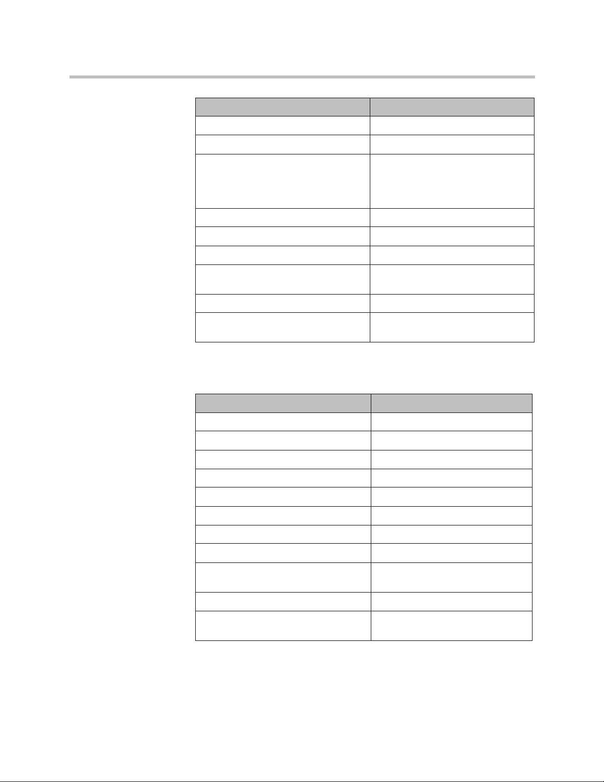
Password Settings for Room, Remote Access, User Passwords
Setting Restriction
Minimum Length • Remote (Admin only):
Set to 15; range is 8 to 15.
• Room (User/Admin):
Set to 9; range is 6 to 20.
Can Contain ID or Its Reverse Form Disabled, not configurable.
Require Lowercase Letters Set to Off, configurable.
Polycom, Inc. 7
Deployment Guide for Maximum Security Environments
Setting Restriction
Require Uppercase Letters Set to Off, configurable.
Require Numbers Set to Off, configurable.
Require Special Characters • Remote (Admin only):
Reject Previous Passwords Set to 10; range is 8 to 16.
Minimum Password Age in Days Set to Off; range is 1 to 30.
Maximum Password Age in Days Set to 60; range is 30 to 180.
Password Expiration Warning in Days Set to 7, Off is not allowed, range is 1
Minimum Changed Characters Set to 4, range is 1 to 4.
Set to 1; range is 1 to 2.
• Room (User/Admin):
Set to Off; range is 1, 2, or All.
to 7.
Maximum Consecutive Repeated
Characters
Set to 2, range is 1 to 4.
Meeting Password Settings
Setting Restriction
Minimum Length Set to Off, range is 6 to 20.
Require Lower Case Letters Set to Off, configurable.
Require Upper Case Letters Set to Off, configurable.
Require Numbers Set to Off, configurable.
Require Special Characters Set to Off, configurable.
Reject Previous Passwords Set to 10; range is 8 to 16.
Minimum Password Age in Days Set to Off, configurable.
Maximum Password Age in Days Set to 60, range is 30 to 180.
Password Expiration Warning in Days Set to 7, Off is not allowed, range is 1
to 7.
Minimum Changed Characters Set to Off, range is 1 to 4.
Maximum Consecutive Repeated
Characters
8 Polycom, Inc.
Set to 2, range is 1 to 4.

Deployment Guide for Maximum Security Environments
Account Management
Setting Restriction
Admin:
• Lock Account after Failed Logins
• Account Lock Duration in Minutes
User:
• Lock Account after Failed Logins
• Account Lock Duration in Minutes
Certificates, Revocation, and Whitelist
These settings can be configured only through the HDX system web inte rface.
Setting Restriction
Set to 3, Off is not allowed.
Set to 1, configurable.
Set to 3, Off is not allowed.
Set to 1, configurable.
Maximum Peer Certificate Chain
Depth
Always Validate Peer Certificates
from Browsers
Always Validate Peer Certificates
from Servers
Revocation Method Configurable.
Allow Incomplete Revocation Checks Disabled, configurable.
Whitelist Enabled, configurable.
Set to 2, configurable.
Enabled, not configurable.
Enabled, not configurable.
Remote Access Settings
Setting Restriction
Idle Session Timeout in Minutes Set to 10, configurable. Off is not allowed.
Maximum Number of Active Web
Sessions
Maximum Number of Sessions per
User (applies to local, web interface,
and serial port sessions)
Set to 25, range is 10 to 50.
Set to 3, range is 1 to 5.
Lock Port after Failed Logins Set to 3, configurable. Off is not allowed.
Port Lock Duration in Minutes Set to 1, configurable. Off is not allowed.
Polycom, Inc. 9
Deployment Guide for Maximum Security Environments
You can configure the period of time, in hours, in which the failed login
threshold must be exceeded to lock the user’s account. This command can
only be changed through the command-line interface using the serial API:
loginwindowduration
: Set to 1, range is 1 to 24. Off is not allowed.
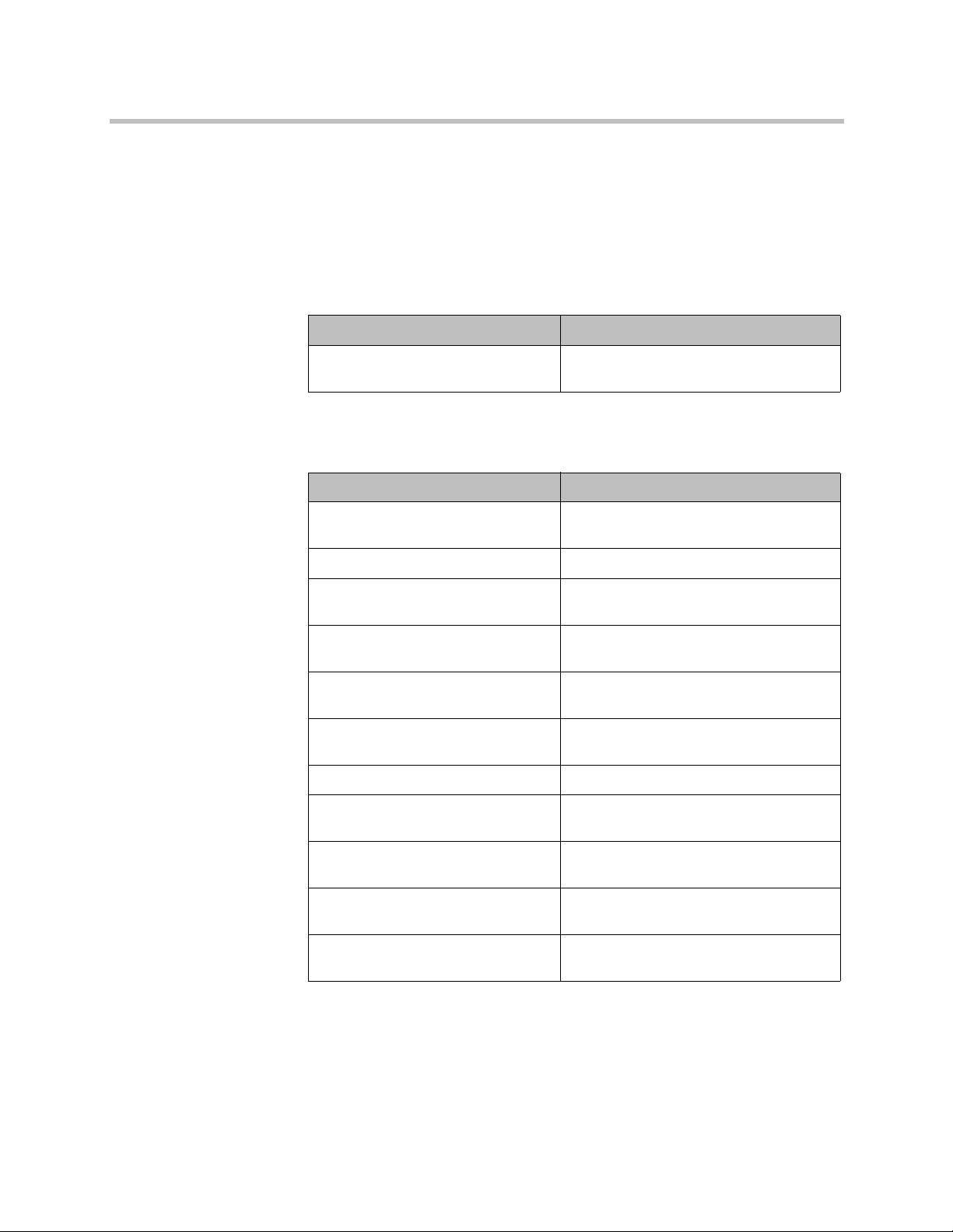
External Authentication
Setting Restriction
Enable Active Directory
Authentication
Enabled, configurable.
Other Settings
Setting Restriction
Serial Ports: RS-232 Mode Set to Off, configurable (only Control is
allowed).
Network > IP Network > Enable SIP Cleared, not configurable.
Global Services > Directory
Servers
System Settings > Auto Answer
Point-to-Point Video
Only LDAP available.
Disabled, configurable.
System Settings > Auto Answer
Multipoint Video
Home Screen Settings >
Availability Control
System Settings > Recent Calls Disabled, not configurable.
Home Screen Settings > Last
Number Dialed
Cameras > Far Control of Near
Camera
System Settings > Call Detail
Report
Global Services > Calendaring
Service
10 Polycom, Inc.
Disabled, configurable.
Enabled, not configurable.
Disabled, not configurable.
Disabled, configurable.
Enabled, not configurable.
Disabled, not configurable.

Deployment Guide for Maximum Security Environments
Locating Your System
The system should be placed in a secured location and on a fire wall-protected
network segment.
To mitigate certain network-based attacks, Polycom recommends that the network
administrator configure port security on the switch to which Polycom devices
connect. Security is enhanced by binding the device’s MAC address to a specific
physical port on the switch. Alternatively, 802.1X can be used to authenticate the
HDX system to the network switch. For more information about the usage of
802.1X, refer to “Install on a Network Using 802.1X” on page 11.
Installing in a Non-DHCP Environment
If you are installing the Polycom HDX system in a non-DHCP environment, you
must manually configure the LAN properties during the setup wizard u sing the
local interface and the remote control. In the LAN properties screen, choose
Enter IP Address Manually and continue through the next screens to finish
configuring the LAN properties.
Install on a Network Using 802.1X
If you are installing the Polycom HDX system on a network that uses 802.1X,
you have the following choices:
• Complete the setup wizard using the local interface and the remote control
so you can enter the 802.1X credentials, which then allows the system to
connect to the network.
• Connect the system to a local network that does not use 802.1X so you
can use the web interface to complete the setup wizard. After you
complete the wizard settings and enter the 802.1X credentials, you can
connect the system to the network that uses 802.1X authentication.
Polycom, Inc. 11
Deployment Guide for Maximum Security Environments
Configuring Your Local System
This section describes how to manually configure system settings to meet the
maximum security requirements.
To configure your system for deployment in a maximum security
environment:
1 Download and install the Polycom HDX 3.1.9 system software onto your
HDX system (if not already present), following the guidance earlier in this
document. For additional information about installing the software, refer to
the release notes for your software version.
2 Configure the network settings to get the system onto the network,
following the previous guidance for non-DHCP or 802.1X environments.
3 When prompted in the setup wizard:
— Enable Security Mode.
— Set the Security Profile to Maximum.
— Set Admin ID to a value other than admin.
— Set an Admin Room Password, an Admin Remote Access Password,
a User Room Password, and a User Remote Access Password that
meet the default password policy as described in “Password Settings
for Room, Remote Access, User Passwords” on page 7.
You can modify the password policies after you complete the setup
wizard. For more information about doing this, refer to “Configuring
Your Room and User Password Policy” on page 16.
— Change the User ID to something other than user.
4 After you complete the setup wizard and the system restarts, log into the
system using the new Admin ID and Room Password that you set.
5 Go to System > Admin Settings > General Settings > Security >
External Authentication to configure the Active Directory Server (ADS)
settings.
6 Go to System > Admin Settings > General Settings > Security >
Security Settings.
Any user account information entered during the setup wizard is not valid after
system restart. ADS is enabled by default in Maximum Security mode, which
disables the local user account.
12 Polycom, Inc.
Deployment Guide for Maximum Security Environments
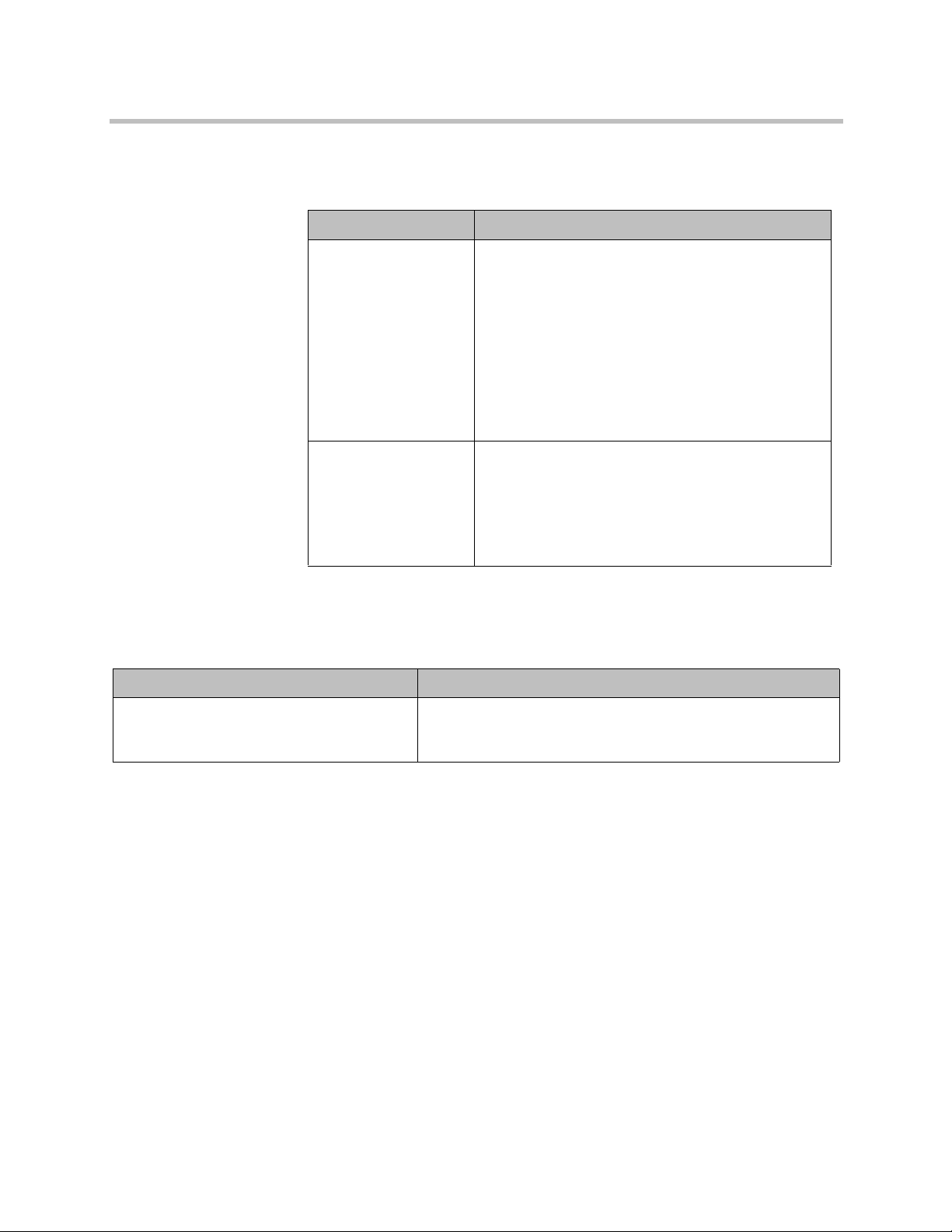
7 Go to System > Admin Settings > General Settings > Security >
Security Settings > > and configure the following settings.
Setting Description
AES Encryption Specifies whether to encrypt calls with other sites.
• Off — AES Encryption is disabled.
• When Available — Allows calls with all endpoints,
including sites that might not support encryption.
• Default: Required for Video Calls Only — Allows
video calls only with sites that support encryption.
ISDN voice and analog phone calls are allowed.
• Required for All Calls — Allows video calls only
with sites that support encryption. ISDN voice and
analog phone calls are not allowed.
Allow Access to User
Settings
Specifies whether the User Setting screen is
accessible to users through the System screen.
• Enable this setting if meeting passwords are
required to join multipoint calls.
• Disable this setting if meeting passwords are not
required for multipoint calls.
8 Configure the system for time and date management using the steps
appropriate for your particular Polycom HDX system model and
deployment type.
Deployment Type Configuration Steps
ISDN-only Deployments
All models
Go to System > Admin Settings > General Settings > Location
> , and set Time Server to Off and manually configure the
time and date.
Polycom, Inc. 13

Deployment Guide for Maximum Security Environments
Deployment Type Configuration Steps
IP Deployments
Polycom HDX 9000
Polycom HDX 9006
Polycom HDX 8000 Hardware Version B
Polycom HDX 7000 Hardware Version B
or later
Polycom HDX 6000
Polycom HDX 4500
Polycom HDX 4000 Hardware Version C
IP Deployments
Polycom HDX 8000 Hardware Version A
Polycom HDX 7000 Hardware Version A
Polycom HDX 4000 Hardware Version A
Polycom HDX 4000 Hardware Version B
All Polycom HDX 4000 systems with Hardware Version A and B, and Polycom 7000
and 8000 systems with Hardware Version A require a connection to an NTP server
to keep accurate time across power outages and system restarts.
Polycom HDX 6000 and 9000 series systems, Polycom HDX 7000 and 8000
systems with Hardware Version B or later, and Polycom HDX 4000 systems with
Hardware Version C have an internal battery-backed real-time clock that allows
them to keep accurate time across power outages and system restarts.
To verify your hardware version:
• For HDX 8000 and 7000 HD systems, you can verify the hardware version by
going to System > System Information. If no hardware version is designated,
your system has Hardware Version A.
• For HDX 7000 systems, the part number indicates the hardware revision. You
can find the part number on the back of the unit.
Hardware Version A part numbers: 2201-27285-XXX and 2215-27427-XXX
Hardware Version B part numbers: 2201-28629-XXX and 2215-28632-XXX
Go to System > Admin Settings > General Settings > Location
> , and do one of the following:
• Set Time Server to Off and manually configure the time and
date.
• Set Time Server to Auto.
• Set Time Server to Manual:
- Enter the NTP server address for the Primary Time
Server.
- Enter the NTP server address for the Secondary Time
Server.
Go to System > Admin Settings > General Settings > Location
> , and do one of the following :
• Set Time Server to Auto.
• Set Time Server to Manual with NTP server address
specified.
- Enter the NTP server address for the Primary Time
Server.
- Enter the NTP server address for the Secondary Time
Server.
9 On Polycom HDX 4000, 4500, 7000, and 8000 series systems, go to
System > Admin Settings > LAN Properties > > , and disable
the Enable PC LAN Port setting, unless its use is required. If you change
this setting, the system restarts.
10 Go to System > Admin Settings > Network > Call Preference, and
configure the following settings on the Call Preference screen.
14 Polycom, Inc.

Deployment Guide for Maximum Security Environments
Setting Description
IP H.323 • Disable this setting for ISDN-only deployments.
SIP SIP is disabled and not configurable in the Maximum
ISDN H.320 • Disable this setting for IP-only deployments.
11 Go to System > Admin Settings > General Settings > Security > Log
Management, and set this setting on the Log Management screen.
Setting Description
• Enable this setting if H.323 calling on IP networks is
required.
security profile.
Note that integration with Microsoft Lync, which uses
SIP is not available in the Maximum security profile.
• Enable this setting if ISDN H.320 calling is required.
Percent Filled
Threshold
• Specifies the percent filled level, which triggers a
system alert. Suggested value: 70.
• This alert is mandated by the Application Security
STIG (APP3650 in V3R3).
12 Go to System > Admin Settings > Pairing, and set the following
settings.
Setting Description
Allow Polycom Touch
Control to Pair with
This System
SmartPairing Mode Choose Disabled for this setting.
SmartPairing uses an ultrasonic protocol to al low devices like PCs and other
personal devices to pair with the system. This may not be appropriate for secure
deployments. Consult your local site administrator before using this feature.
Clear this setting unless a Polycom Touch Control panel
will be used with the system.
Polycom, Inc. 15

Deployment Guide for Maximum Security Environments
Configuring Your System for Remote Access
This section describes how to configure the system to meet the maximum
security requirements for remote access thr o ug h th e RS-23 2 se ria l por t or
through the HDX system web interface.
When you configure the system to use the Maximum Security Profile, the
system:
• Requires devices that are attempting to start a session through the serial
port to provide either an Admin ID and password or a User ID and
password. If you are connecting interactively using a terminal emulator
program, press Enter to display a login prompt. If yo u ar e con n ec tin g by
using a serial control application, send a new line character to display a
login prompt.
• Requires you to set separate remote access passwords for both the User
and Admin accounts. The Use the Room Password for Remote Access
setting is automatically disabled in the Maximum Security Profile and is not
configurable. You configure the remote access password initially during
the setup wizard, and you can make changes later using the Admin
Settings screens.
• Makes available different API command s depending on whether you log in
with the Admin account or with the User account.
• Locks the serial port after a specified number of failed login attempts. The
port lockout causes the HDX system to refuse further log-in attempts for a
period of time, which you can configure. Each serial port has its own
separate port lockout.
• Displays a Security Banner with the serial port login. You cannot set the
Security Banner to Off. To configure the Security Banner, go to System >
Admin Settings > General Settings > Security > Security Settings
> > > and set a Security Banner to either Custom or DoD.
• Automatically terminates idle sessions (a configurable setting).
Configuring Your Room and User Password Policy
Though passwords defined as being strong are recommended for security
purposes, keep in mind that strong passwords require the use of the on screen
virtual keyboard to enter letters and special characters. This requirement can
make it possible for others to view a password as you enter it. You can mitigate
this risk by using longer numeric-only passwords that you can enter using the
remote control or keypad. You can enter any combination of characters and
maintain security by using a keyboard connected to the HDX system through
the USB port. This section gives the recommended settings for both
configurations.
16 Polycom, Inc.

Deployment Guide for Maximum Security Environments
Support for the USB keyboard is specifically to enter complex login information
such as for Active Directory accounts. For all other system interaction, use the
remote control or keypad.
To configure your room password policy:
1 Go to System > Admin Settings > General Settings > Security >
Password Settings > Admin Room Password, and configure the
password settings to meet your site password security policies.
2 Go to System > Admin Settings > General Settings > Security >
Password Settings > User Room Password, and enter the
corresponding settings for the User Room Passw or d.
3 Go to System > Admin Settings > General Settings > Security >
Password Settings > Remote Access Passwords, and en ter the
corresponding settings for the Remote Access Password.
Configuring the System to Use Certificates
The Polycom HDX system supports the use of PKI certificates for additional
security. You can manage certificates and revocation only by using the
Polycom HDX system web interface. Make sure the app ro pr iat e ce rtif ica te
authority (CA) and identity certificates are available on your computer so that
you can upload them.
For more information, refer to the Administrator’s Guide for Polycom HDX
Systems.
Detecting Intrusions
The Polycom HDX system logs an entry to the security log when it detects a
possible network intrusion. The security log prefix identifies the type of pa cket
detected, as shown in the following table.
Prefix Packet Type
SECURITY: NIDS/unknown_tcp Packet that attempts to connect or probe a
SECURITY: NIDS/unknown_udp Packet that probes a closed UDP port
SECURITY: NIDS/invalid_tcp TCP packet in an invalid state
closed TCP port
SECURITY: NIDS/invalid_icmp ICMP or ICMPv6 packet in an invalid state
Polycom, Inc. 17

Deployment Guide for Maximum Security Environments
Prefix Packet Type
SECURITY: NIDS/unknown Packet with an unknown protocol number in
the IP header
SECURITY: NIDS/flood Stream of ICMP or ICMPv6 ping requests or
TCP connections to an opened TCP port
Following the message prefix, the security log ent ry inc lud es the time sta m p
and the IP, TCP, UDP, ICMP, or ICMPv6 headers. For example, the following
security log entry shows an “unknown_udp” intrusion:
2009-05-08 21:32:52 WARNING kernel: SECURITY: NIDS/unknown_udp
IN=eth0 OUT= MAC=00:e0:db:08:9a:ff:00:19:aa:da:11:c3:08:00
SRC=172.18.1.80 DST=172.18.1.170 LEN=28 TOS=0x00 PREC=0x00
TTL=63 ID=22458 PROTO=UDP SPT=1450 DPT=7788 LEN=8
Viewing Network Interface and System Status
Network Interface Status
The network interface status is indicated by the lights on the network interface
module.
Quad BRI Network Interface Status Lights
The network interface lights are located on the network interface module.
Indicator Light Connection Status
Green and yellow lights off Indicates one of the following situations:
Green light on The system is receiving a clock signal
• No power to the system.
• The system is not connected to the
network.
• The system is not receiving a clock
signal from the network.
• The system is restarting.
from the network.
18 Polycom, Inc.

Deployment Guide for Maximum Security Environments
Indicator Light Connection Status
Yellow light on The system is able to make a call.
Green and yellow lights on Indicates one of the following situations:
PRI Network Interface Status Lights
The network interface lights are located on the network interface module.
Indicator Light Connection Status
Green and yellow lights off No power to the system.
Red light on or blinking Indicates one of the following situations:
• The system is receiving a software
update.
• The system is operating normally.
• The system is not connected to the
ISDN network.
• There is a problem with the ISDN
line.
Yellow light on or blinking There is a problem with the ISDN line.
Green light on The system is able to make and receive
Viewing System Status
You can view the System Status screen on the local system or by using the
HDX system web interface. The System Status screen displays system status
information, including auto answer point-to-point, remote control battery,
IP network, meeting password, log threshold, and ISDN lines.
If the system detects that any of the ISDN BRI SPIDs are incorrect or that an ISDN
line is connected to the wrong ISDN port on the network interface module, the
System Status screen displays a red arrow for that line. If this happens, ensure the
ISDN and SPID numbers are correct.
To view the System Status on the system:
1 Go to System > Diagnostics > System Status.
2 For an explanation of any of the status items, select the item and press
calls.
on the remote control or keypad.
Polycom, Inc. 19

Deployment Guide for Maximum Security Environments
To view the System Status using the Polycom HDX web interface:
1 Open a web browser , and in the browse r address line enter th e system IP
address, for example,
web interface.
2 Click Diagnostics from any page in the Polycom HDX web interface. 3 For an explanation of any of the status items, click the item.
https://10.11.12.13
Using the Camera Privacy Cover
The Polycom EagleEye camera goes to sleep when the Polycom HDX system
does. For added security Polycom now offers a privacy cover (part number
2215-28454-001) that you can attach to the camera. You can open and close
the cover as needed. Contact your Polycom distributor for more information.
, to go to the Polycom HDX
Using the API with a Secure RS-232 Interface
You must log in with a password to start an RS-232 session when the system
is configured with the Maximum Security Profile and if the system is configured
for external authentication through Active Directory . For more information, refer
to “Configuring Your System for Remote Access” on page 16.
20 Polycom, Inc.

Deployment Guide for Maximum Security Environments
Data Cleansing
Data cleansing is a result of resetting an HDX system, “cleaning” or removing
sensitive data. You can return the system to its original state and remove the
HDX system environment software as well as the data, or you can remove the
data but leave the HDX system environment software. Removing the data and
environment software is known as erasing the system flash memory, while data
cleansing retains the environment software but removes the data.
With HDX system software version 2.7.0_J and later, issuing the following
parameters with the
programming interface) removes user- and site-specific data from the
non-volatile memory, which is also called flash memory:
resetsystem
command using the API (application
•
•
•
•
•
Using any one of the previous parameters is equivalent to the data cleansing
portion of a process known as “erase system flash memory.” That is, if you
issue the command
deletelogs
other settings are affected.
However, if you issu e the command
deletelocaldirectory deletelogs deletecdr deletecertificates
will get the same result as using the Erase System Flash Memory option for a
software upgrade on the HDX system’s web interface. The erase system flash
memory process returns the HDX system to its default state, thereby removing
user- and site-specific data and reloading the HDX system environment
software.
CGI Commands
deletesystemsettings
deletelocaldirectory
deletelogs
deletecdr
deletecertificates
resetsystem deletelocaldirectory
, only the local directory or system logs will be deleted. None of the
or
resetsystem
resetsystem deletesystemsettings
, you
The following table describes the Common Gateway Interface (CGI)
commands.
Command Description
a_abkcommand.cgi Handles all address boo k commands such as add, delete, and update
entries
a_apicommand.cgi Runs API commands from the web interface
a_authprovisioning.cgi Registers the HDX system with the provisioning service
Polycom, Inc. 21

Deployment Guide for Maximum Security Environments
Command Description
a_callhangup.cgi Hangs up a call if the system is in a call
a_changepassword.cgi Validates and updates passwords on the system
a_colorbar.cgi Toggles the color bar for video diagnostics
a_convertcsvtodatfiles.cgi Imports the system profile in .csv format into .dat files
a_createdatfilecsv.cgi Creates a list of configuration values in .csv format that excludes machine
sensitive information
a_detectcamera.cgi Initiates camera detection
a_downloadlogpkg.cgi Downloads the complete system log package
a_downloadpanasonicsettings.cgi Downloads the Panasonic settings into a file
a_exportdirectoryasabk.cgi Exports the contacts information into an xml file that can be imported back
into the HDX system
a_getcdr.cgi Gets the call detail report (CDR) from the system
a_getcurrentlog.cgi Downloads the current system logs
a_getentrycount.cgi Gets the count of contacts in the system
a_getlog.cgi Downloads the system logs
a_getloglist.cgi Generates a list of log files on the system in xml format
a_getprovisionstatus.cgi Returns the latest provision status of the system
a_getvalue.cgi Gets the configuration variables value
a_importdirectoryascsv.cgi Imports the directory in xml format
a_installpkg.cgi Installs the wild card language package
a_iscallconnected.cgi Determines whether the system is in a call
a_manualdial.cgi Dials a site manually
a_nearendloop.cgi Toggles the near end loop
a_ping.cgi Pings the hostname
a_provisionsystem.cgi Provisions the system with the profile attribute of the CGI
a_removelogo.cgi Removes the custom logo from the system
a_resetsystem.cgi Restarts the system
a_screencapture.cgi Captures the current screen
a_security.cgi Validates and sets the password related security settings
a_sendmessage.cgi Displays a message to the system user
a_setchaircontrolfunction.cgi Performs chair control operations
22 Polycom, Inc.

Deployment Guide for Maximum Security Environments
Command Description
a_speakertest.cgi Runs the speaker tests
a_traceroute.cgi Generates a trace route from the system
a_uploadlogo.cgi Uploads/removes the system logo from the system
a_validate.cgi Validates the parameters and their values
addcert.cgi Adds the certificate to the system
addcrl.cgi Adds the certificate revocation lists (CRL) to the system
addgmsurl.cgi Adds the Global Management Server (GMS) URL to the system
addrbooklist.cgi Gets the address book list
currentscreen.cgi Creates an image of the current screen
deletegmsurl.cgi Deletes the GMS URL from the system
downloadclientcsr.cgi Downloads the client Certificate Signing Request (CSR) from the system
downloadservercsr.cgi Downloads the server CSR from the system
far_image_1.jpg If the video on the web is on, returns the current far image
generatecsr.cgi Generates the system CSR
getcert.cgi Loads the user-specified certificate into the system
getmaxmeetingspeed.cgi Gets the meeting maximum speed
isserverready.cgi Checks whether the web server is responding
near_image_1.jpg If the video on the web is on, returns the current near image
poccalibration.cgi —
querystatus.cgi Returns the system status information in xml/txt format
removecert.cgi Removes the installed certificate from the system
removecrl.cgi Removes the installed CRL from the system
savesettings.cgi Saves the system profile in csv format
sendmessage.cgi Displays the message on the vide o screen
sessioncmd.cgi Logs the user out of the system
softupdate.cgi Uploads the software upda te package and validates the uploaded package
swu_cancel.cgi Cancels the software update and reboots the system
swu_custom.cgi Sets the list of settings to change for custom softupdate
swu_display.cgi Sets display settings
swu_getcurrentpage.cgi Reloads the current web page
Polycom, Inc. 23

Deployment Guide for Maximum Security Environments
Command Description
swu_lan.cgi Sets LAN settings
swu_optionkey.cgi Sets and validates the option key
swu_ping.cgi Returns “I am alive” message
swu_progress.cgi Reports the progress of the software update
swu_retain.cgi Sets the user configuration settings to retain
swu_softwarekey.cgi Sets and validates the software key
swu_startupdate.cgi Begins the softupdate process
swu_switchmode.cgi Switches the system to softupdate mode
swu_updaterestoreimage.cgi Reloads the current web page
swu_updatetasks.cgi Sets the update tasks to be performed
swu_updatetype.cgi Sets the type of update to perform, typical or custom
updatetime.cgi Updates the system time
whitelistupdate.cgi Updates the Whitelist with the allowed patterns of the IP addresses
writeclosedcaption.cgi Displays closed captioning on video screen
Placing a Test Call
T o troubleshoot any issues making video calls, call a Polycom video site to test
your setup. A list of worldwide numbers that you can use to test your Polycom
system is available from the Polycom Video Test Numbers.
Try these best practice methods:
• Make sure the number you dialed is correct, then try the call again. For
example, you might need to dial 9 for an outside line or include a long
distance access code or country code.
• To find out if the problem exists in your system, as k the person you were
trying to reach to call you instead.
• Find out if the system you are calling is powered on and is functioning
properly.
• If you can place calls but not receive them, make sure that your system is
configured with the correct number.
24 Polycom, Inc.

Deployment Guide for Maximum Security Environments
Conditions of Fielding
a The HDX system must be incorporated in the site’s PKI. If PKI is not
incorporated, the following findings will be included in the site’s
architecture:
» DSN13.17 for HDX 7000 family, HDX 4000 family, HDX 6000
family, HDX 9000 family, and HDX 8000 family.
» NET0445 for HDX 7000 family, HDX 4000 family, HDX 6000
family, HDX 9000 family, and HDX 8000 family.
b An NTP Server is required for proper system operation as te sted. This
is needed to provide the correct time and date for the following
systems: HDX 7000 family, HDX 4000 family, HDX 6000 family, HDX
9000 family, and the HDX 8000 family.
c The HDX system must be integrated into the site’s AD environment for
authentication and authorization requirements.
d The site must deploy the solution on separate Virtual Local Area
Networks and be behind the site’s firewall.
e The site must deploy the solution in a secure area.
f The configuration must be in compliance with the Polycom family’s
Rel. 3.1.9 military-unique features deployment guide.
g The site must register the system in the Systems Networks Approval
Process Database as directed by the DSAWG and Program
Management Office at https://snap.dod.mil/index.cfm.
Polycom, Inc. 25
 Loading...