

Page 1
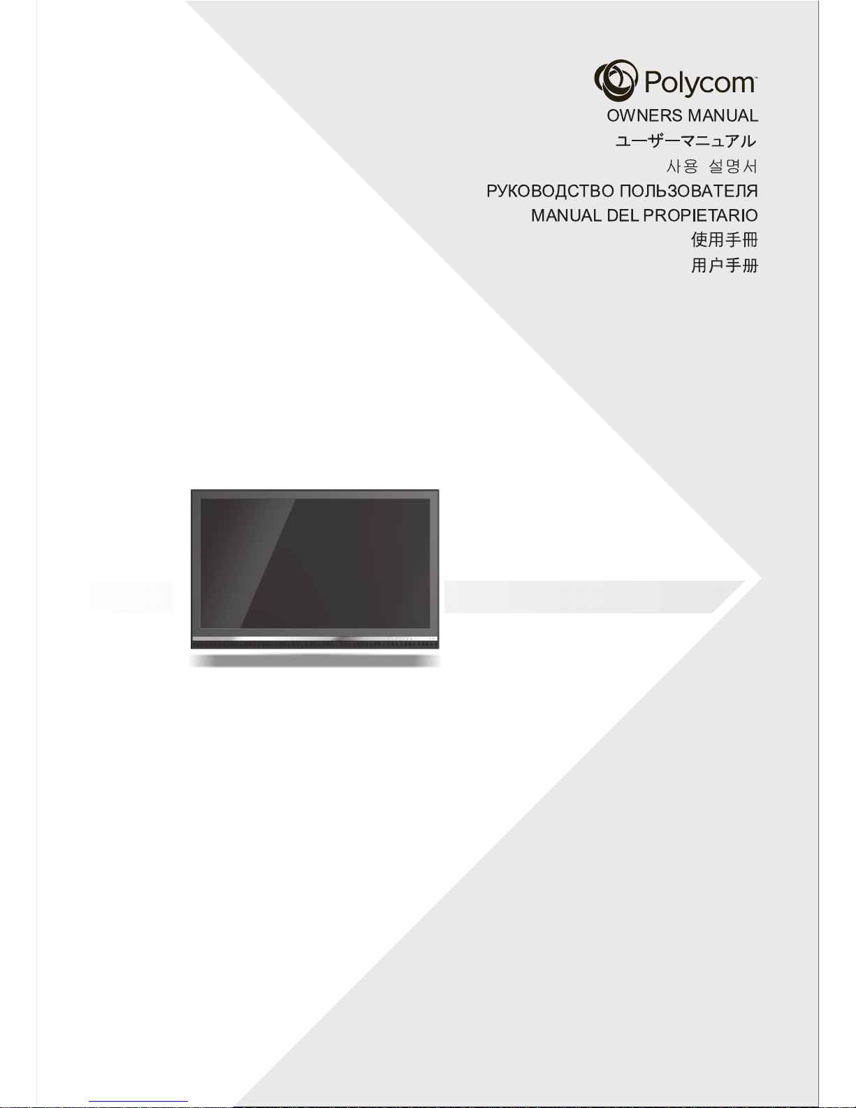
65” LED DISPLAY
イインチチ デディィスププレ
65
ン
LED
ス レ
イイ
디디스스플플레레이이
65” LED
СД-ТЕЛЕВИЗОР С
Д
ИАГОНАЛЬЮ 65"
MONITOR LED 65”
65
吋吋
LED
顯顯示示器器
65
吋吋
LED
显显示示器器
Page 2

Table of Contents
02
1
2
Important Safety Instructions
Warnings & Precautions
Cleaning & Maintenance
Regulatory Notice
Overview
Checking the Accessories Supplied
Keypad Controls
Battery Installation
Rear Panel Connections
Remote Control Buttons
3
4
4
6
6
6
7
8
3
6
Special Notices
3
3
4
5
Using the OSD Menu
Installation
Connecting POLYCOM Video Conferencing System
Connecting a DVD
Connecting a Set-Top Box
Connecting an External Amp
lifier
Connecting an External Amplified Speaker
Connecting a PC
Menu System
Picture Adjustment
Fine Tuning Under RGB Mode
Additional Information
Troubleshooting
Specifications
RS-232 Connection
Dimensional Drawings
Color Scheme
Packing Break Out
9
10
10
10
11
11
15
16
19
20
23
25
25
11
26
10
15
19
Supported Resolutions
14
Explanation of Various Picture Control Settings
15
Timing For Component
Command Format and Sequencing
21
Understanding Widescreen Modes
17
Setup Adjustment
Explanation of Various Setup Settings
17
Assembly Information
17
27
23
Connecting a IR Receiver
13
Page 3

Use only handles on back of monitor for lifting. Monitors require two people to lift.
Important Safety Instructions
03
WARNING
RISK OF ELECTRIC SHOCK
DO NOT OPEN
WARNING: To reduce the risk of electric shock, do not remove the front or back covers.
No user-serviceable parts inside. Refer servicing to qualified service personnel only.
Read and keep these instructions.
Follow all instructions.
Heed all warnings.
The unit should be operated from the type of power source indicated on the label. If the type of available
power is unknown, consult your dealer or local power company.
Do not use this apparatus near water.
Clean with damp cloth or cleaner approved for cleaning LCD screen.
Do not block any ventilation openings. Install in
accordance with the manufacturer’s instruction.
Do not install near any heat sources such as rad
iators, heat registers, stoves, or other apparatus (including
amplifiers) that produce heat.
Do not defeat the safety purpose of the polarized or grounding-type. A polarized plug has two blades with
one wider than other. A grounding type plug has two blades and third grounding prong. The wide blade or
the third prong are provided for you safety. If the provided plug does not fit into your outlet, consult an
electrician for replacement of the obsolete outlet.
Protect the power cord from being walked on or pinched particularly at plugs, convenience receptacles, and
the point where they exit from the apparatus.
Only use attachments/accessories specified by the manufacturer.
Use only with the cart, stand, tripod, bracket, or table specified by the manufacturer, or sold with the
apparatus. When a cart is used, use caution when moving the cart/apparatus combination to avoid injury
from tip-over.
Unplug this apparatus during lightning storms or when unused for long periods of time.
Refer all servicing to qualified service personnel. Servicing is required when the apparatus has been
damaged in any way, such as power-supply cord or plug is damaged; liquid has been spilled or objects have
fallen into the apparatus, the apparatus has been exposed to rain or moisture; does not operate normally; or
has been dropped.
Do not overload wall outlets and extension cords as this can result in a risk of fire or electric shock.
Do not hit this panel . Be careful to prevent from getting hurt by broken glass pieces in case the panel breaks.
Be sure to install the display unit according to the installation instruction recommended by the manufacturer.
Upon completion of service or maintenance, request the service technician to perform safety check to ensure
that the display unit isinproperoperatingcondition .
0 0
This display unit onlyoperateswithinthetemperature 0 Cto 40 C.Operationoutsideoftherecommendation
may cause damage toyourproduct .
Certain programs may be copyrighted and unauthorized recording in whole or in part may be in violation
of copyright laws in the U.S. and Canada.
FCC/CSA regulations state that any unauthorized
modifications to this display may void user authority to
operate it.
Special Notices
The lightning flash with arrow-head
Warning & Precautions
within a triangle is intended to inform
the user that parts inside the product
are a risk of electric shock.
The exclamation point within a triangle
is intended to tell the user that important
operating and servicing instructions are
explained.
!
!
When a wall mount bracket is used, ensure the display is sufficiently tightened
from tip-over.
to the wall mount to avoid injury
Page 4
Important Safety Instructions
04
Cleaning & Maintenance
Disconnect from the electric outlet before cleaning. Do not use liquid or aerosol cleaners. Use only
a slightly damp cloth or cleaner approved for cleaning LCD screen.
Regulatory Notice
CE Statement
The CE label on this product indicates that it complies with the 89/336/EEC directive on
electromagnetic compatibility and safety rules as defined in the 2006/95/EC, low voltage directives
and the 2009/125/EC Eco-design directive for Energy-using products.
This product is protected against interferences from other electronic devices, provided that these
devices comply with the standards in force. Sporadic interferences may happen nevertheless.
FCC Statement
The Federal Communications Commission Radio Frequency Interference Statement includes
t he follo wing w arning :
This equipment has been tested and found to comply with the limits for a Class B digital device,
pursuant to Part 15 of the FCC Rules. These limits are designed to provide reasonable protection
against harmful interference in a residential installation.
The equipment generates, uses, and can radiate radio frequency energy and, if not installed and used
in accordance with the instructions, may cause harmful interference to radio communications. However,
there is no guarantee that interference will not occur in a particular installation. If this equipment does
cause harmful interference to radio or television receptions, which can be determined by turning the
equipment off and on, the user is encouraged to try to correct the interference by one or more of the
following measures :
Reorient or relocate the receiving antenna.
Increase t he separat i on b et ween t he equipment a nd r ecei ver.
Con n ect the equipment into an outlet on a circuit different from that to which the receiver is connected.
Con sult t he d ealer or an e xper ien ced radio/display technician for help.
Disconnect the unit from the main supply and refer servicing to qualified service personnel under
the following conditions :
Power cord or plug is damaged or frayed.
Liquid has been spilled into the product and/or the unit has been exposed to water or moisture.
Unit does not operate normally when the operating instructions are not followed. Adjust only those
controls that are covered by the operating instructions, improper adjustment of other controls may
result in damage which often requires extensive work by a qualified technician to restore the unit
to normal operation.
Unit has been dropped or the cabinet has been damaged.
Unit exhibits a distinct change in performance, indicating a need for service.
Users must use the mounting device and means provided specifically for the appratus, or UL listed
wall mount bracket with loading capacity of 33.4kg, to mount it, or the equivalent.
Page 5
05
Important Safety Instructions
Warning
User must use shielded signal interface cables to maintain FCC compliance for the product. Provided
with this display is a detachable power supply cord with IEC320 style terminations. It may be suitable
for connection to any UL listed personal computer with similar configuration.
Before making the connection, make sure the voltage rating of the computer convenience outlet is the
same as the monitor and that the ampere rating of the computer convenience outlet is equal to or
exceeds the monitor voltage rating. For 120 Volt supplications, use only UL listed detachable power
cord with NEMA configuration 5-15P type (parallel blades) plug cap. For 240 Volt applications use
only UL listed detachable power supply cord with NEMA configuration 6015p type (tandem blades)
plug cap.
IC Compliance Notice
This Class B digital apparatus meets all requirements of the Canadian interference-Causing
Equipment Regulations of ICES-003.
ROHS Compliance Statement
This displ ay def ined in t his owner m an u al is 100% ROHS compliant and meets all the
req ui r em ent s set fort h in European Union Di rect i ve 2011/65/EU
,Restriction of the
Use of Certain Hazardous Substances in Electrical and Electronic Equipment.
Used electrical and electronic equipment must be treated separately and in
accordance with legislation that requires proper treatment, recovery and recycling
of used electrical and electronic equipment. When this crossed-out wheeled bin
symbol is attached to a product, it means the product is covered by the European
Directive 2002/96/EC. If you wish to discard of this product, please contact your
local authorities and ask the correct method of disposal. The correct disposal of
your old product will help to prevent potential negative consequences for the
environment and human health.
Attention : If you want to dispose of this equipment, please do not use the ordinary
dust bin!
Information on Disposal for Your Old Product
Page 6

06
Overview
Checking the Accessories Supplied
LCD Display
User’s Manual
Keypad Controls
Status LED
Red-Standby
Solid Green-Power on
Power(Standby) Button
Turns power on from standby mode.
There is a wait period between
on/standby cycles.
Adjustment Buttons
These keys serve as navigation and
adjustment keys when On Screen Display
menu is engaged.
Select Buttons
Use these buttons to navigate through the
On Screen Display menu.
Menu Button
Use this button to engage the On Screen
Display menu.
Input Button
Use this button to switch between available
inputs.
1
3
2
4
5
6
Sponge
Clips & Screws
Remote Controller
& Batteries
1 3 4 5
2
6
x4
Battery Installation
The LED will illuminate in orange color if
the display is at standby mode and the
main power cord is plugged into the back
of the unit.
OWNERS MANUA L
ユーザーマニュアル
사용 설명서
РУКОВОДСТВО ПОЛ ЬЗОВАТЕЛ Я
MANUAL DEL PROPI ETARIO
使用手冊
用户手册
65” LED DISPLAY
OWNERS MANUA L
ユーザーマニュアル
사용 설명서
ОВОДСТВО П ЛЬЗОВАТЕЛЯ
MANUAL DEL PROPI ETARIO
使用手冊
用户手册
65” LED DISPLAY
IR Receiver
& Cable Clips
x4
Page 7

07
Rear Panel Connections
1
RGB Input
Connect to RGB input of computer or Set-Top Box.
Component Video Input
Auto-detecting component video input (Y/Pb/Pr
or Y/Cb/Cr) for connecting to the component
output of video conferencing system, DVD player
or Set-Top Box.
Audio Output
Variable or fixed audio output jacks for connecting
to an external audio amplifier.
RS-232 Connector
Connect to a computer serial port.
*HDMI, the HDMI logo and High-Definition Multimedia
Interface are trade marks or registered trademarks
of HDMI Licensing LLC
*The USB port is labelled. It is provided for after
service/engineer use ONLY.
5
2
3
4
Connect to the digital video signals from
HDMI 1 /HDMI 2 Inputs
a Set-Top Box or PC video connector.
DVI is also supported through HDMI, using a DVI
to HDMI adapter cable.
Note:
1
23
4
5
6
6
IR receiver for the remote control. Connect to IR
IR Input
input of the display.
Page 8

Standby Power On/off
POLYCOM Mode
Pu sh t h is k ey t o se lect P OLY C OM m o des f or
op tim al c o nfe renc e per for man ce.
Remote Control Buttons
1
2
Press Exit button to close the
screen.
Number Keypad
These keys are not applicable for this display.
Quick View
This key is not applicable for this display.
Wide
Toggles between various aspect ratio settings.
Menu
Engages the On Screen Display menu.
VOL. / ADJ.
On Screen Display menu
For adjusting volume function, it is not applicable for
this display.
Use ADJ. keys to scroll through the On Screen Display
menu.
3
4
5
6
7
SEL.
Use SEL. button up or down to
Screen Display menu.
navigate through the On
EXIT
Direct Input Selection Keys
Directly change input signal modes.
Input Select
Press to select input signal modes sequentially.
8
9
10
11
2
11
12
13
15
16
14
1
4
6
10
7
8
9
5
3
Push this button to turn on the display from standby mode.
Push it again to standby mode.
Sound Mute On/Off
To mute or restore the sound. (Only applicable if optional
side mounted or external amplified speaker are connected
directly to the display.)
Info.
Press to show the status of the display.
Q.Access
This key is not applicable for this display.
Sleep
12
13
14
15
Press this key to engage sleep timer selection directly.
Recall
Recall default setting.
16
Overview
08
AV key is not applicable for this display.
Note:
Page 9
Overview
09
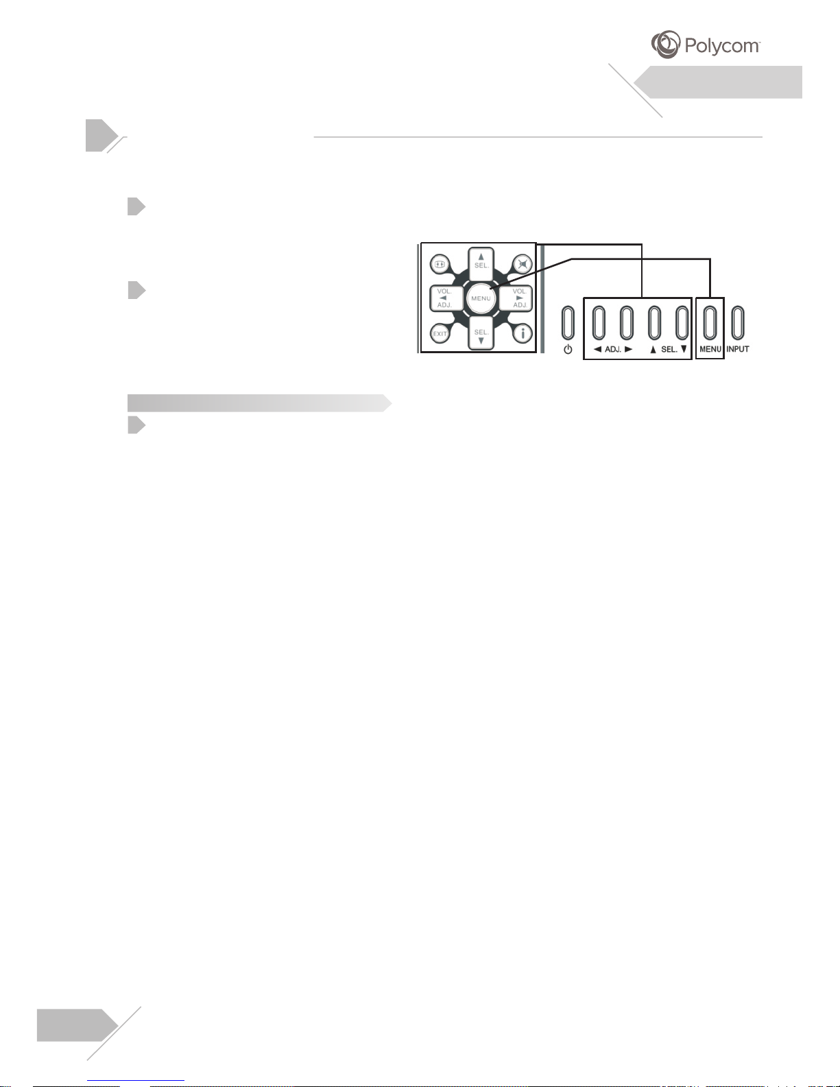
To access the OSD menu, press “MENU”
button on the remote control or on the
rear cover.
Navigation through the OSD menu
can be accomplished by using the
“Left/Right” or “Up/Down” keys on
remote control or rear cover.
The On Screen Display (OSD) menu allows access to setup various parameters equipped
with this display.
After change settings on the OSD menu, the new settings are confirmed automatically
when OSD picture vanish.
OSD Menu
Navigation
OSD Menu
Access
Using the OSD Menu
1
2
Note:
1
Page 10
Refer to the Administrator’s Guide included with the POLYCOM video conferencing system
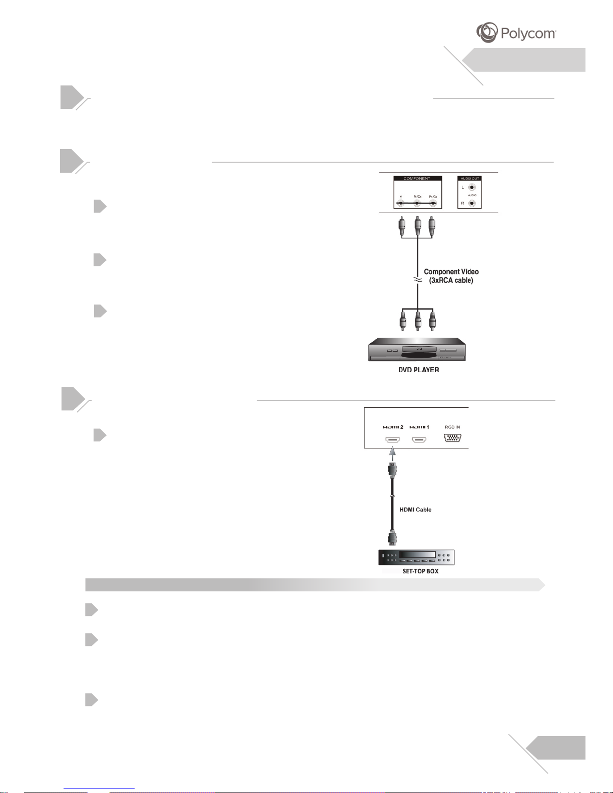
for configuring the monitor(s) for optimal performance.
Using Component Video Input
Connect the green-colored (labeled as Y)
jack from the DVD to the green-colored
jack of the display.
Connect the blue-colored (labeled as PB/CB)
jack from the DVD to the blue-colored PB/CB
jack of the display.
Connect the red-colored (labeled as PR/C )
jack from the DVD to the red-colored PR/CR
jack of the display.
Connecting POLYCOM Video Conferencing System
R
Connecting a DVD
1
2
3
Installation
Using HDMI Input
Connect the HDMI connector from the back
of the Set-Top Box to the HDMI connector
located on the back of the display.
Some Set-Top Boxes may not have a HDMI output. Use Component Video input or RGB
input method if this is the case.
Upon connecting your Set-Top Box to the HDMI input of the display, it may be necessary
to adjust various picture setting on the display or to correctly match the output of the
Set-Top Box. This is caused by the different video timing set by various Set-Top Box
manufacturers.
If the external device has DVI output only, use a DVI to HDMI adapter cable to connect to
the HDMI terminal.
Connecting a Set-Top Box
1
Notes:
1
2
3
10
Page 11
Installation
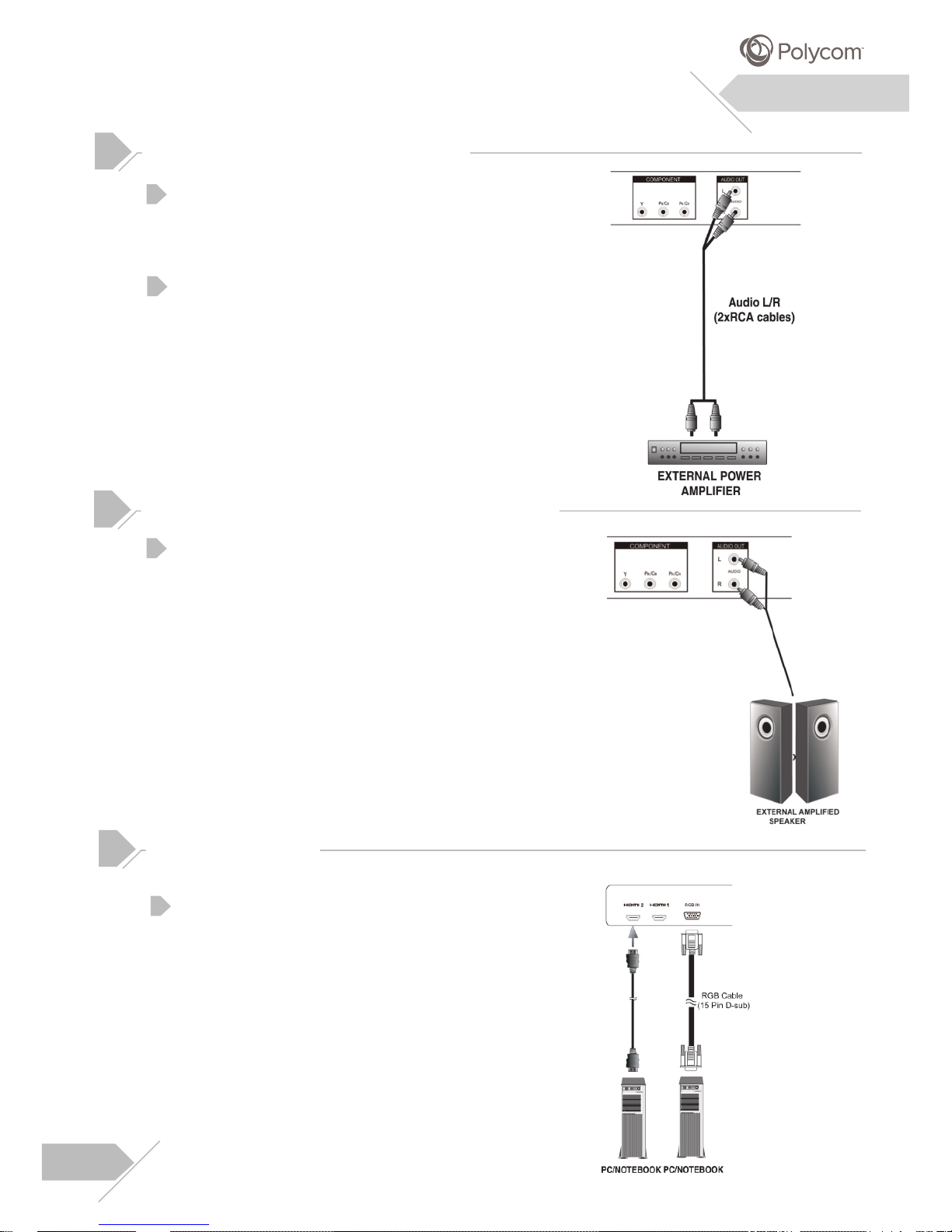
This display can be connected to an external
amplifier using the AUDIO OUT jacks located
on the back of the display.
Connect the red (R) and white (L) AUDIO
OUT jacks from right side of the connector
panel to the external amplifier.
Connect the red(R) and white(L) audio out
sockets located to the right of the connector
panel of the set respectively to the right and
left amplified speaker.
Connecting an External Amplifier
Connecting an External Amplified Speaker
Using RGB or HDMI Video Input
For most PCs, connect the 15-pin D-Sub
RGB connector from the back of the PC to
the RGB-IN Connector located on the back
of the display.
1
2
1
1
11
Connecting a PC
Page 12
Setting Up Your Display Using Plug and Play
This display adheres to VESA Plug and Play standard to eliminate complicated and time
consuming setup of displays. This display identifies itself to the computer and automatically
sends the PC its Extended Display Identification Data (EDID) using Display Data Channel
(DDC) protocols.
How To Set Up Your Display with PC (Windows)
The display settings for a typical Windows-based computer are shown below; however,
actual screens on your computer will differ depending on the version of Windows and video
equipped with the computer. Even though the actual screen may look different from example
displayed below, basic set-up routine will apply in most cases.
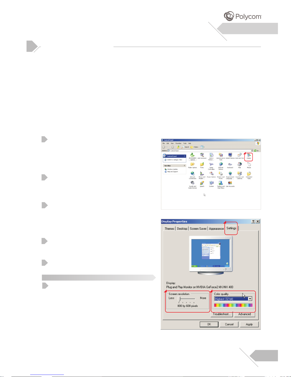
Go to Window’s CONTROL PANEL by
clicking: START, SETTINGS, CONTROL
PANEL. The CONTROL PANEL Window is
displayed. Select the DISPLAY icon from this
window.
The DISPLAY PROPERTIES dialog box is
displayed. Select the SETTINGS tab to
display your computer’s video output settings.
Set the “Screen Resolution” setting to
1920x1080p PIXELS. For COLOR QUALITY,
select 30 BIT COLOR (might also be
expressed as 1073 million colors).
If a vertical-frequency option exists, set the
value to 60Hz.
Click OK to complete the setting.
Note:
Both screen position and size will vary,
depending on the type of PC graphics card
and its resolution selected.
Connecting a PC (con’t)
1
2
3
4
Installation
5
1
2
3 4
1
12
Page 13
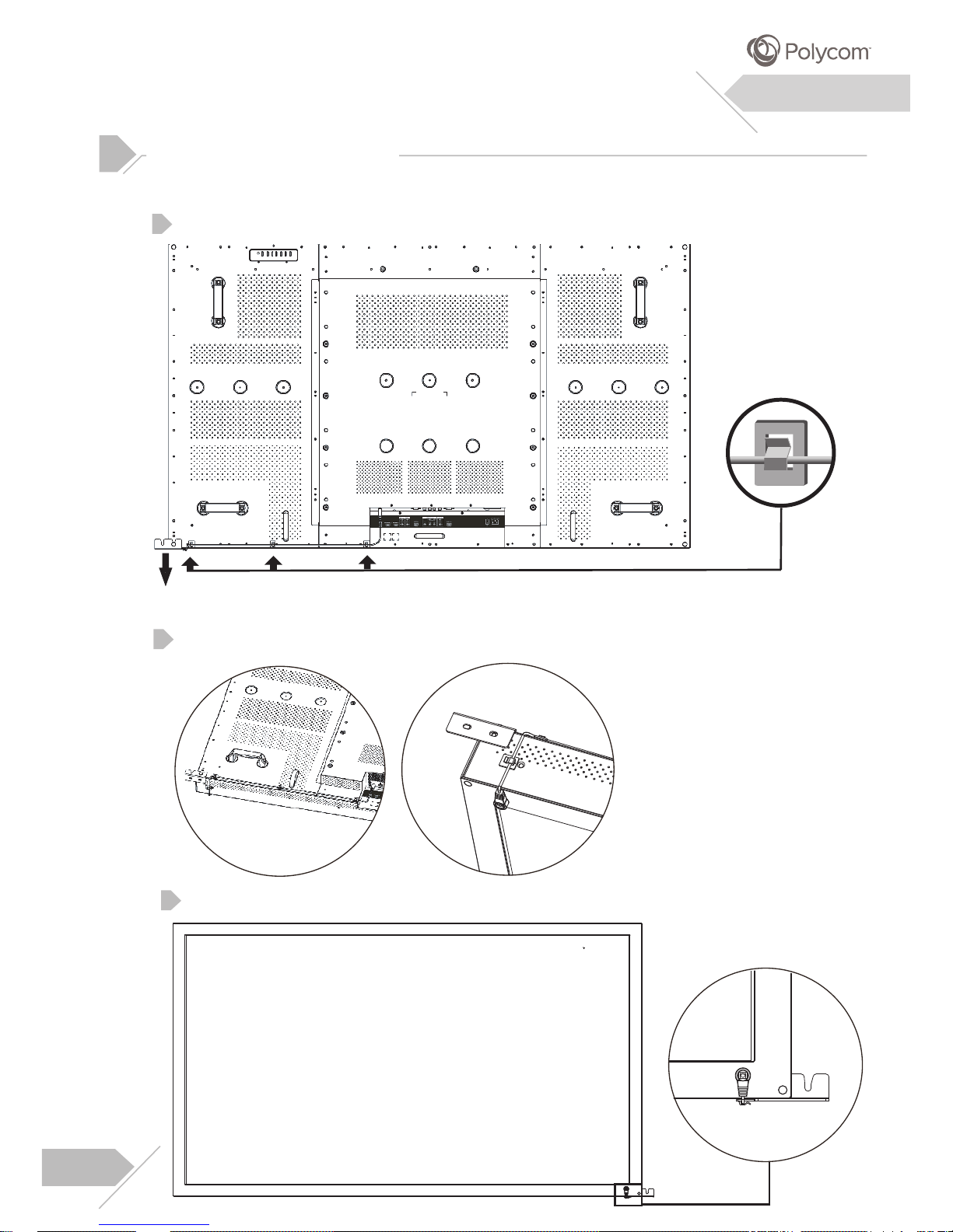
IR receiver for remote control (suggested position is shown as below)
Plug in the IR connector from the back of the display.
Use 4 cable cilps to fix the cable and IR receiver.
Connecting a IR Receiver
1
Installation
2
13
Use double-side adhesive tape to paste the IR receiver on the right bottom of front bezel.
3
(This clip is an optional accessory for jointing 2 displays. Please refer to page 27.)
(Cable Clip)
Page 14
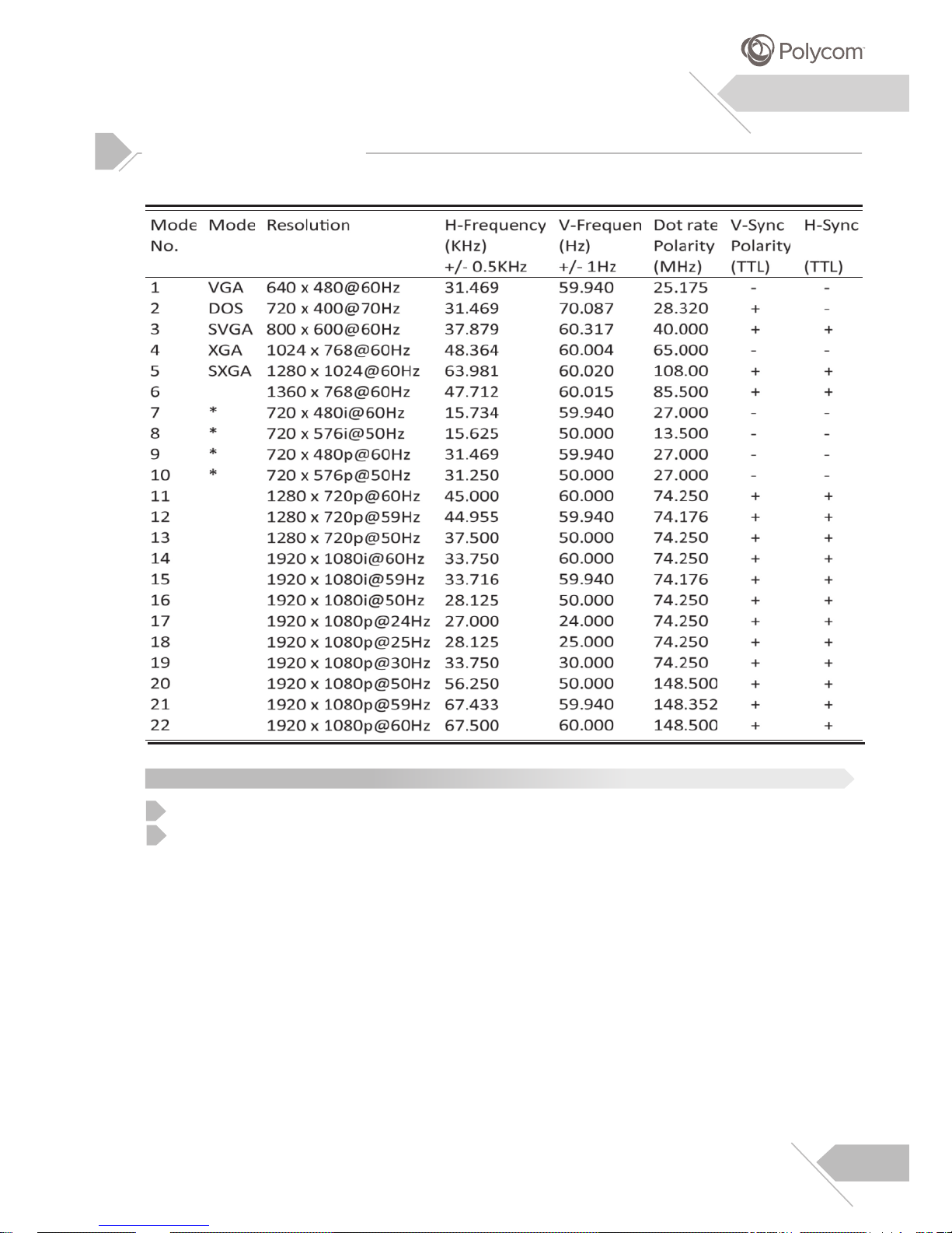
Under HDMI, DVI and RGB modes, this Display supports the following resolutions:
Supported Resolutions
Installation
This display does not support Macintosh resolution.
“*”:not available for RGB Mode.
Note:
1
2
14
14
Page 15
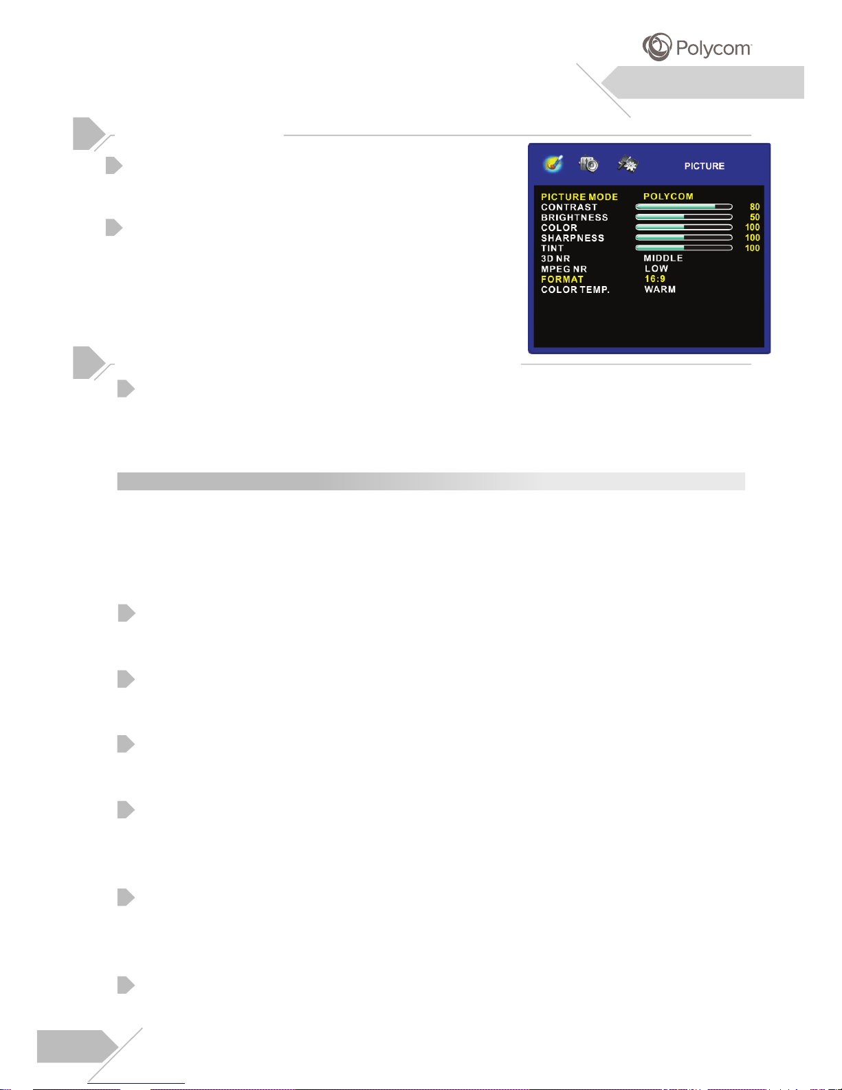
There are four preset picture modes that you can choose from to optimize the video picture
according to the type of programming you are watching. (1)POLYCOM (2)CUSTOM (3)MILD
(4)VIVID.
CONTRAST
Adjust Contrast to increase the level of “White” in the video picture. Increasing Contrast will
make white area of the video picture brighter. Contrast works in conjunction with Brightness.
BRIGHTNESS
Adjust Brightness to enhance the level of dark area in the video picture such as night
scenes and shadow scenes. Increasing brightness will make dark areas more visible.
COLOR
Use color to adjust the color saturation of the picture. Increasing color will make the color
more intense. Reducing color setting will make the color less intense.
SHARPNESS
Use sharpness to adjust the amount of detail enhancement to the video picture. Increase
the setting will enhance the edges of objects in the video picture. Decreasing the setting
will reduce enhancement.
TINT
Use Tint to adjust the color of flesh tones. Increasing color will make the picture with
more red in appearance. Decreasing setting in left direction will shift the picture with more
green in appearance.
3D NR/MPEG NR
To improve the quality of the picture in the case of poor reception.
Picture Adjustment
Explanation of Various Picture Control Settings
Menu System
PICTURE MODE
Note:
Note that the default Picture Mode setting is set to “POLYCOM”. This setting is standard
mode, which is optimized (and recommended) for use with POLYCOM Video conferencing
system for all video inputs. As such, many of the adjustment sub-settings are “grayed-out” and
are not accessible to the user. In order to make adjustments to these settings, “CUSTOM”
picture mode must be selected.
Press the “Menu” button on the rear cover or remote
control and “Down” key to enter PICTURE menu.
Various picture settings are available from
the Picture menu. Use “Left/Right” keys to adjust
that you wish and press “Exit” key to confirm select.
1
2
15
Page 16
Menu System
Explanation of Various Picture Control Settings (con’t)
Use to change various screen width modes. There are two modes to choose from:
(1)16:9 (2) 4:3.
FORMAT
AUTO ADJUST
Use AUTO ADJUST to fine-tune the display to perfectly synchronize to the video signal
source under RGB mode.
COLOR TEMP.
Select the COLOR TEMP. for white balance. There are three setting to choose from:
(1)Natural (2)WARM (3)COOL.
CLOCK
Use clock to fine-tune the monitor to perfectly ADC PLL divider clock ratio synchronize to
the video signal source under RGB mode.
PHASE
Use phase to fine-tune the monitor to perfectly ADC clock phase synchronize to the video
signal source under RGB mode.
V-POSITION
Use to change vertical position of the picture. Increase to shift the picture up. Decrease to
shift the picture down.
H-POSITION
Use to change horizontal position of the picture. Increase to shift the picture to the right.
Decrease to shift the picture to the left.
Picture Quality Adjustment
Due to various PC video cards with different specifications, it is likely that the initial video
picture has subtle noise or imperfections. Please use the following procedures to adjust the
picture quality when using under RGB mode
Picture Quality Adjustment-Manual-Manual Adjustment
In certain special cases, users may desire to manually adjust. To do so, please follow below
procedure. Due to various PC video cards with different specifications, it is likely that the
initial video picture may not fit exactly to the size of the display. Please use the following
Fine Tuning Under RGB Mode
Press “Menu” key on the rear cover or remote control.
procedures to adjust the picture position.
1
Use “Down” key to enter Picture option from the menu.
2
Use “Up/Down” keys to select AUTO ADJUST option from the menu.
3
Use “Left/Right” keys to change the setting till your video picture is optimal.
4
1
Press “Menu” key on rear cover or remote control.
Use “Down” key to enter PICTURE option from the menu.
2
Use “Up/Down” keys to select H-Position or V-Positon from the menu and press keys to
confirm selection.
3
Use “Left/Right” keys to change the setting till your video picture is best fit within the display
area of display.
4
16
Page 17
Understanding Widescreen Modes
This display is capable of displaying a wide-screen image on the native 16:9 aspect ratio
screen. However, not all available video content fits perfectly in a wide-screen (16:9) format
resulting in unused screen space. This display is capable of displaying images in various
formats that is suitable for various types of content depending on its size.
For 4:3 (Square) Content
Content from traditional TV, VCR and some DVD’s are formatted using a “square” 4:3 format.
When viewing content in this “Square” format, the following viewing modes are suitable.
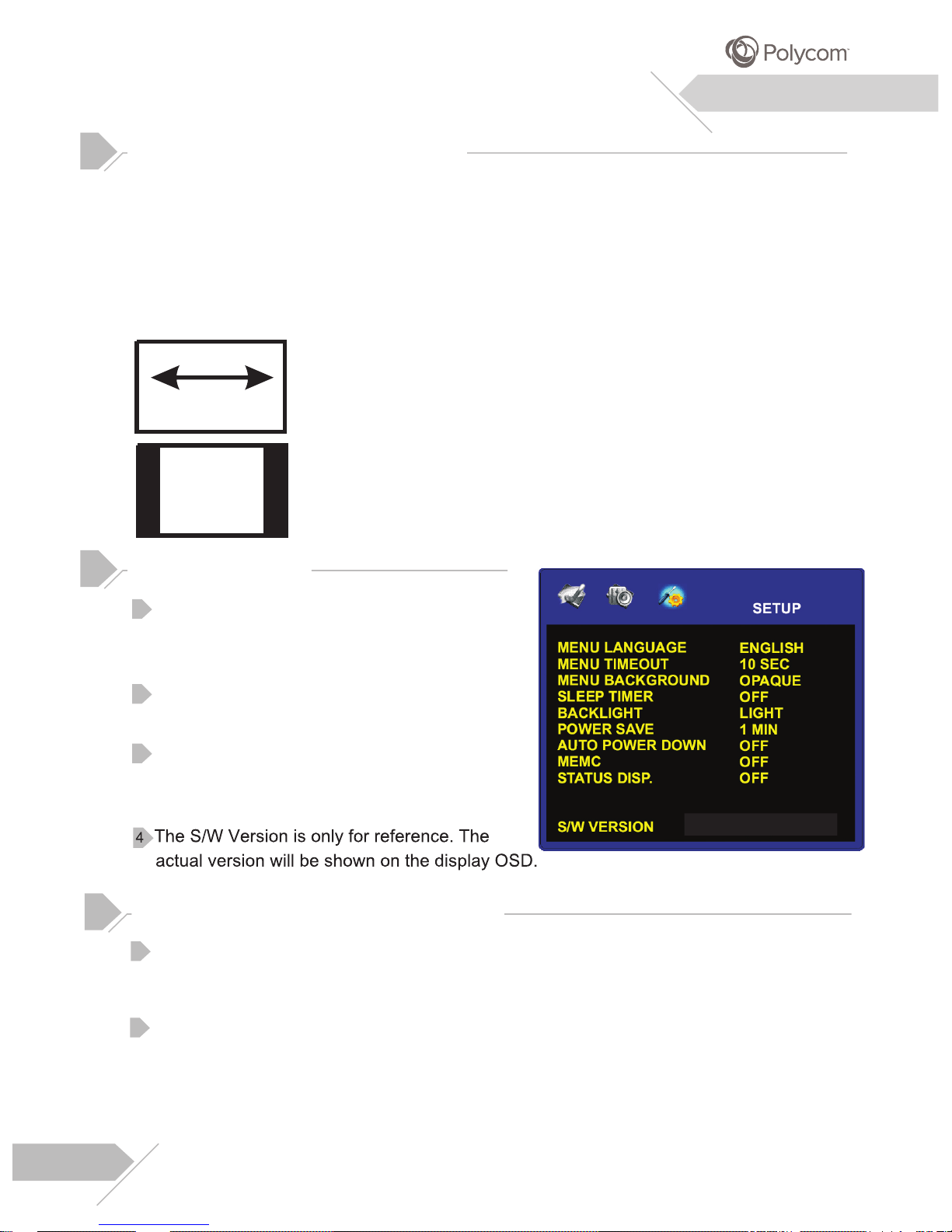
16:9 (WIDE)
The original 4:3 image is proportionally stretched to fill the entire screen.
This is the default setting from factory.
4:3 (NORMAL)
In 4:3 mode, the original 4:3 image is preserved but black bar are used
to fill the extra space on the left and right.
matically shut-off
without
will automatically go into
works with HDMI/ RGB
Press the “Menu” key on the rear of cover or
Explanation of Various Setup Settings
remote control. Use “Left/Right” keys to select
the SETUP Option from the menu.
Use “Up/Down” keys to select the option that
you wish to adjust.
Use “Left/Right” keys to change the setting. After
achieving desired setting, press “Exit” key to
close the OSD
.
1
2
Setup Adjustment
3
Menu System
SLEEP TIMER
After user selects the sleep time option, the display will auto
user intervention.
POWER SAVE
When there are no signals detected by the display, the display
sleep mode until signal is restored. Power save mode /feature
and Component input options.
17
PME65MA-YYMMDD
Page 18
Explanation of Various Setup Settings
Menu System
18
Page 19
The following table lists possible problems and methods for remedy. Please refer to this table
prior to contacting a service representative.
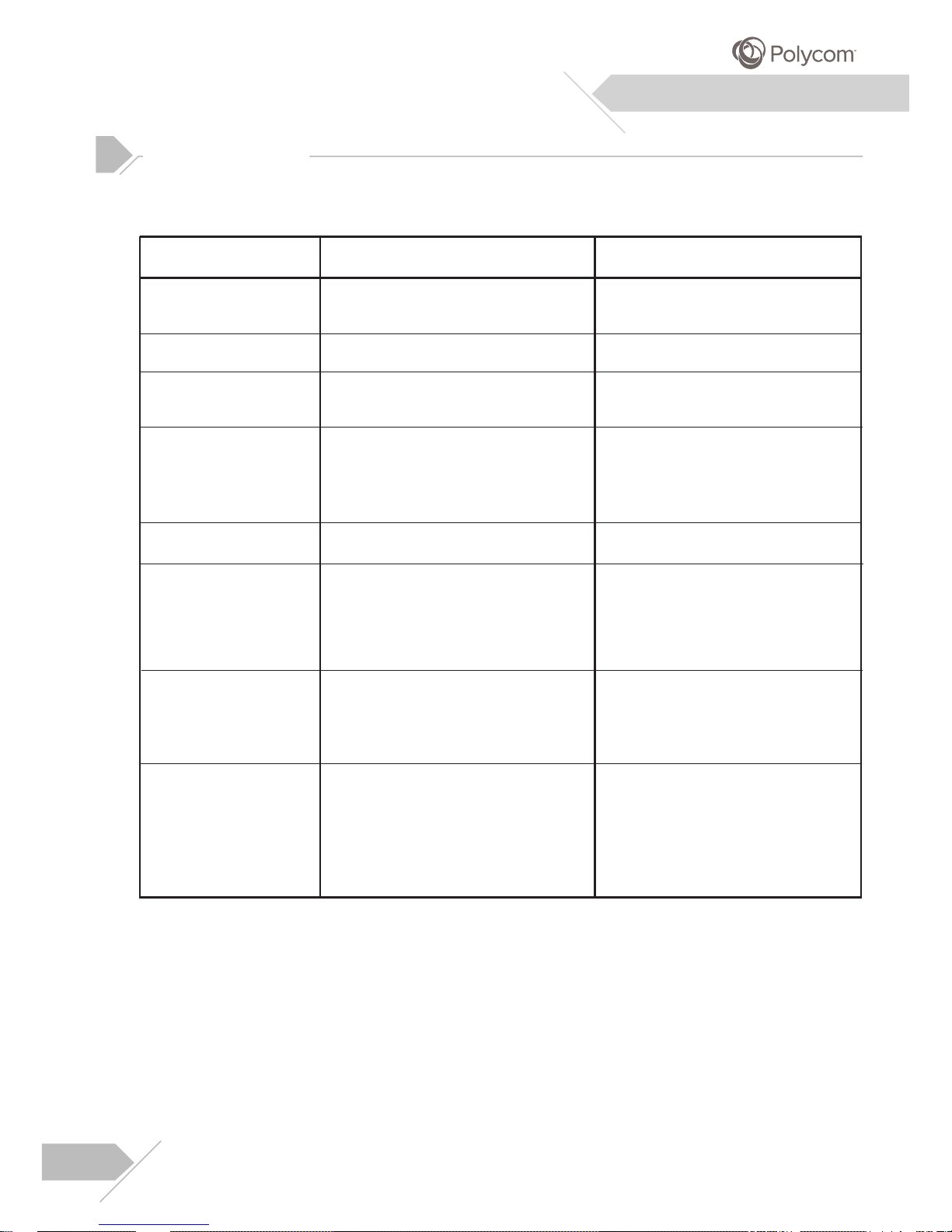
Troubleshooting
Symptom
Possible Cause
Remedy
No picture is displayed.
1. The power cord is disconnected.
2. The selected input has no connection.
3. The display is in standby mode in RGB mode.
1.Plug in the power cord.
2.Connect the selected device to the display.
3.Press any key on your keyboard.
Poor picture or poor sound.
Color is abnormal.
Image doesn’t fill up the full
size of the screen.
1. Electronic appliances, cars, motorcycles or
fluorescent lights may be nearby.
1.Move the display to another location to
reduce interference.
1. The signal cable is not connected properly.
1.Make sure that the signal cable is attached
firmly to the rear panel of the display.
1. The signal cable is not connected properly.
2. The input signal is not supported by the
display.
1.If under VGA mode, the Format settings
are incorrectly set.
1.Make sure that the signal cable is attached
firmly.
2.Check that the video signal source is sup ported by the display (refer to the specific ations section).
Picture is distorted.
1.Use the Format options in the PICTURE
menu to adjust the size of the picture.
The remote control buttons
do not work.
Some picture elements do
not light up.
After-Images can be seen
on the display after it has
been powered off.
(Examples of still pictures
include logos, video games,
computer images and images
displayed in 4:3 format)
1.The remote control batteries are flat or
incorrectly installed.
2.The position of the selection switch does not
correspond to the selected input.
1. Some pixels of the display may not turn on.
1. A still picture was displayed for an
extended period of time.
1. Change the batteries. Please note that
you must then reprogram the remote
control.
2.Put the selection switch on the correct
position.
1.This display was manufactured using an
extremely high level of technology;
however, sometimes some pixels of
the display may not display. This is not
a malfunction.
1.Do not allow a still image to be
displayed for an extended period of
time as this will cause a permanent
after-image to remain on the screen.
Additional Information
19
Page 20
Specifications
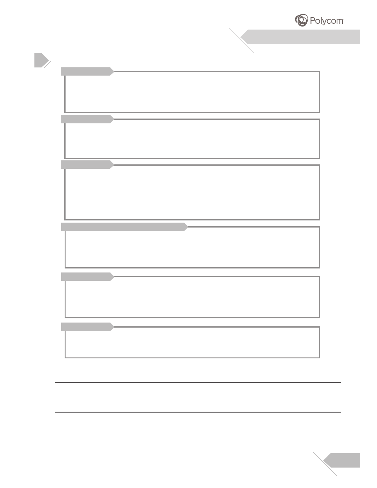
16:9
1920(Horizontal) x 1080p(Vertical) pixels
0.744 mm x 0.744 mm
2
360 cd/m
65” -
Display Panel
Screen size
Aspect ratio
Number of pixels
Luminance
100 ~240 Vac, 50/60 Hz
2.0 A Max.
200 Watts Max.
0.4 Watts Max.
Power Source
Input voltage
Input current
Power consumption
Stand-by
Video Component RCA in Jack x 1 set
Audio L/R Out Jack x 1 set
15 Pin D-Sub for RGB x 1 set
19 Pin HDMI x 2 sets
9 Pin D-Sub for RS-232 x 1 set
3.5Φ Phone Jack for IR Receiver x 1 set
Connection
Connector Types
Analog
Positive
AV:1Vp-p(with sync), CB/PB:0.7Vp-p, CR/PR:0.7Vp-p
H:support to 15K~68KHz V:support 24~60Hz
Y/CB/CR or Y/PB/PR Signal (Component)
Type
Polarity
Amplitude
Frequency
TTL
Positive or Negative
RGB:0.7Vp-p
H:support to 27K~68KHz V:support to 24~70Hz
RGB Signal
Type
Polarity
Amplitude
Frequency
Digital
Positive or Negative
H:support to 15K~68KHz V:support 24~70Hz
HDMI Signal
Type
Polarity
Frequency
Additional Information
1. RED
2. GREEN
3. BLUE
4. GND
5. GND
6. REDGND
7. GREENGND
8. BULEGND
9. 5V
10. GND
11.NC
12.SDA
13. H-SYNC
14. V-SYNC
15 SCL
Pin Assignments For D-Sub connector (In/Loop out)
20
Page 21

Pin Assignments For 19 Pin HDMI Connector (Digital only)
1.HDMI_RX2+
2.Ground (For +5V)
3.HDMI_RX2-
4.HDMI_RX1+
5. Ground (For +5V)
6.HDMI_RX1-
7.HDMI_RX1+
8.Ground (For +5V)
9.HDMI_RX0-
10.HDMI_RXC+
11.Ground (For +5V)
12.HDMI_RXC-
13.No Connect
14.Connect
15.RX5VDDC SCL
16.RX5VDDC SDAt
17. Ground (For +5V)
18. IN_5V
19. RX_HOTPLUG
Specifications
Additional Information
Timing For Component
Maximum Resolution Up to 1920 x 1080p
This display does not support Macintosh resolution.
Note:
1
2
21
Page 22
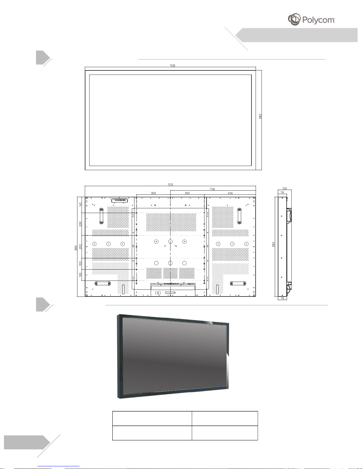
Dimensions & Weight
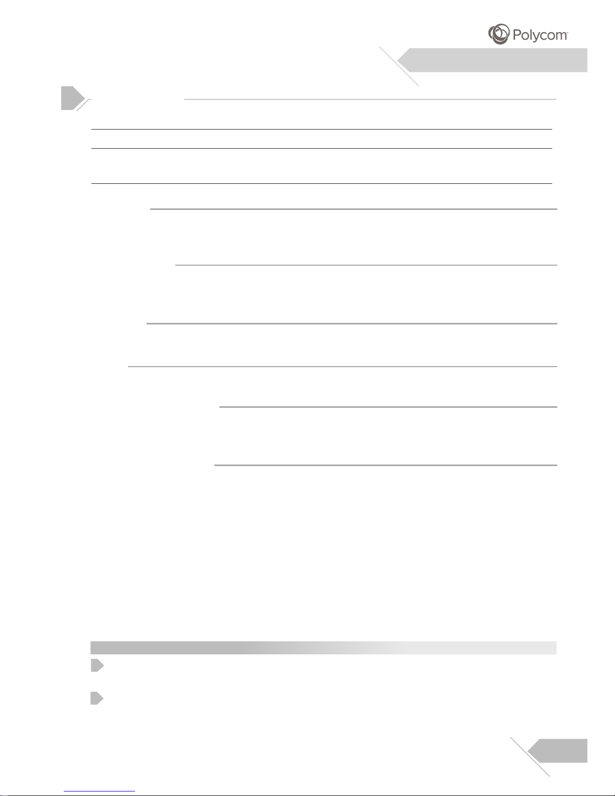
Width
Height
Depth
Net Weight
Gross
Weight
1512mm 882mm 120mm 62.0Kg 75.5Kg
136.7lb 166.5lb
Additional Information
Specifications
Operating
0
Temperature 0~40 C
Relative Humidity 10~90%
Non-Operating
0
Temperature -20~60
C
Relative Humidity 10~90%
Acoustics
(IHF A-weight 1 meter) 32dB Max.
Sound
Audio Output (only for HDMI) Audio Input +/- 3dB
Reliability Requirement
0
The MTBF is 50,000 hrs.(back light) under operation 25 5C. (Half luminosity,
motion picture)
+
Emission Requirement
The unit shall meet the EMI limits in all screen modes as qualified by CB/CE/UL/FCC/
VCCI/ CCC/Gost-R/S-Mark/Spring Mark and KC.
Power Management
Mode
Normal
Stand-by
Power Saving
Power Saving
H-sync
Pulse
No pulse
Pulse
No pulse
V-sync
Pulse
No pulse
No pulse
Pulse
Video
Active
No video
B(blanked)
B(blanked)
Power Dissipation
Normal power
Less than 0.5 Watt
Less than 0.5 Watt
Less than 0.5 Watt
The power indicator LED color is green in normal state, red in stand-by and power
saving state.
Note:
1
22
This display offers a power management feature that is enabled by default, and that
can be used to automatically transition from On Mode to Sleep Mode.
2
Page 23
Additional Information
RS-232 Connection
This monitor is equipped with an RS-232 serial terminal for using the monitor with computer controls.
The RS-232 serial terminal conforms to the RS-232 interface specification. The computer will require
software application (such as Hyper Terminal) which allows the computer to send and receive control
data that can support the communication parameters described in the section.
Interface Parameters
These parameters are required to setup communications with the monitor.
Specification
Sync Method
Baud Rate
Parity
Character Length
Stop Bit
RS-232
Synchronous
9600 bps
None
8 Bits
1 Bits
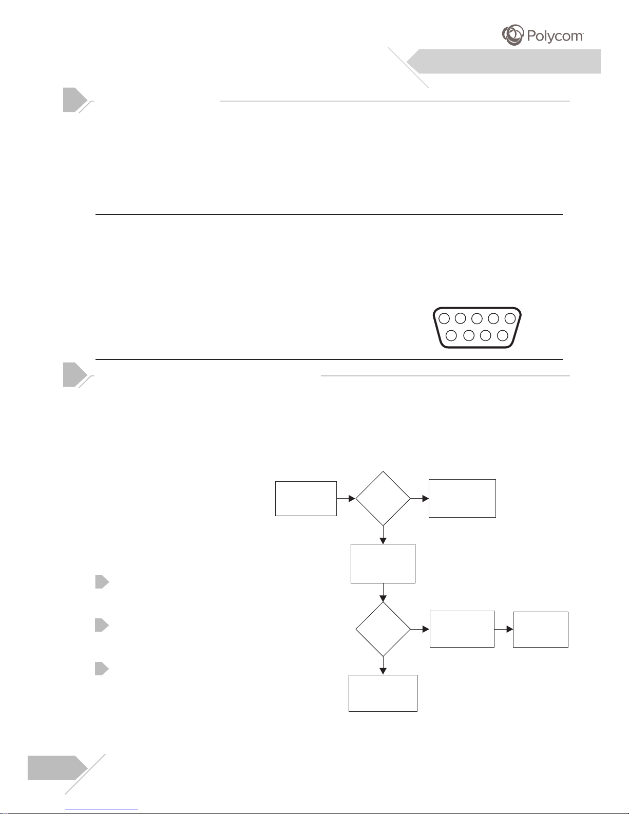
RS-232 Pint Layout
Pin 1 Received Line Signal Detector (Data Carrier Detect)
Pin 2 Received Data (RXD)
Pin 3 Transmit Data (TXD)
Pin 4 Data Terminal Ready (DTR)
Pin 5 Signal Ground
Pin 6 Data Set Ready (DSR)
Pin 7 Request To Send (RTS)
Pin 8 Clear To Send (CTS)
Pin 9 Ring Indicator
1
2
3
4
5
6
7
8
9
RS-232
Command Format and Sequencing
Data
Structure Overview
In
order to transmit data from the computer to the display, the data must be sent in a structured
format. The format used by this display follows a COMMAND:DATA sequence. All commands and
its related data are formatted using a 3-character format separated by a colon in-between. For
example, the Power On command is sent as: PWR:PON where PWR is telling the display that it is
receiving a Power related command, followed by the actual command to carry out.
Communications Overview
As commands are sent from the PC,
the display will provide feedback
regarding the state of command
execution back to the PC. The
display provides information status
to inform the following:
Whether the command sent by
the computer was received by
the display.
Whether the COMMAND : DATA
structure was correctly formatted
for execution by the display.
Whether the command sent
was successfully carried out by
the display.
Overview
PC sends
command to
display
Display
busy?
Display sends
BZY(busy)
status to PC
Display sends
RCV(received)
status to PC
Command
structure sent
correctly?
Display executes
command
Display sends
CFM(confirm)
status to PC
Display sends
FAL(Failure)
status to PC
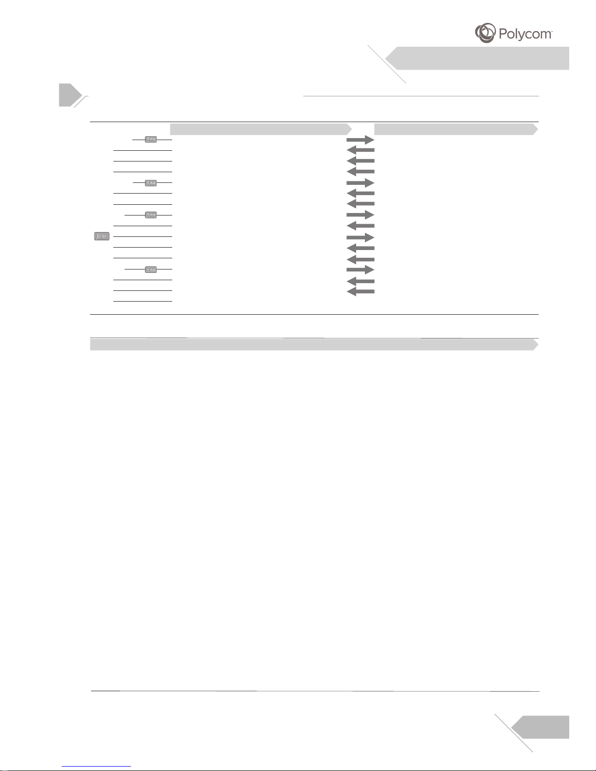
The following is an example of the communication process between the PC and the display using a
program such as Hyper Terminal.
Example: Read Power Status followed by Power On command and input select to AV with disruption.
1
2
3
23
Page 24
Additional Information
>REA:PWR
>RCV
>OFF
>CFM
>PWR:PON
>RCV
>CFM
>INP:AV1
>BZY
>
>RCV
>CFM
>INP:AV1
>RCV
>CFM
>
PC Status
Send command to read power status
Rcv acknowledgment of command received
Rcv OFF status from display
Rcv confirmation of command complete
Send command to POWER ON the display
Rcv acknowledgment of command
Rcv confirmation of command complete
Send command to switch to AV1 input
Rcv acknowledgment of command not accepted
Send command to void previous command
Rcv acknowledgment of command received
Rcv confirmation of command complete
Send command to switch to Av1 input again
Rcv acknowledgment of command received
Rcv confirmation of command complete
Ready to send another command
Display Status
Display rcv command
Send confirmation of comm and rcv’d to PC
Send actual status of power to PC(OFF)
Send confirmation of command completion
Display is not busy and waiting for command
Send confirmation of command rcv’d to PC
Display powers on and sends confirmation
Display is busy doing another task
Send busy status because it can’t rcv data
Rcv command to clear previous command
Send confirmation of command rcv’d to PC
Clear command buffer and sends confirm
Display is not busy and rcv’s command
Send confirmation of command rcv’d to PC
Display switche to AV1 and sends confirm
Command Format and Sequencing
Communications Overview
Display is ready to accept another command
Command and Data Tables
Description
Read Data
Power On/Off
Brightness
Contrast
Color
Tint
Sharpness
Input Select
V-Position
H-Position
Recall
Mute
Language
All Black
Polycom mode
Aspect Ratio
Keypad Lock
Color Temp
Display Model Nam
e
Return Model Name
Command
REA
Power On Source
PWR
BRT
CON
CLR
TNT
SHP
INP
VPS
HPS
RCL
MUT
LNG
BLK
PLC
ZOM
FPL
TMP
DSP
REA
Data
PWR,BRT, CON, CLR, TNT, SHP, INP, MUT, LNG, TMP, ZOM, FPL,
POS
PLC, VPS, HPS, RCL, INF,PTM, 3DN, MPNPOS, BLK,
PON=Power On, OFF=Power Off
001...100
001...100
001...100
001...100
001...100
CP1=Component, RG1=RGB, HDM=HDMI1, HM2=HDMI2
001...100
001...100
000
MON=Mute, OFF=Normal
ENG=English, SPA=Spanish, FFR=French, ITA=Italian, DEU=German,
SWE=Swedish
BON=All Black, OFF=Return
000
WID=16:9, NOR=4:3 with black bars
FO1=Lock, OFF=Unlock
MID=Natural, HIG=Cool, 65D=Warm
INF (Example: DSP:INF RCV CFM PME65MA)
INF (Example: REA:INF RCV CFM PME65MA) CFM
OFF=Normal (Last Memory) CP1=Component, RG1=RGB, HDM=HDMI1,
HM2=HDMI2
Enter
Enter
Enter
Enter
Enter
Picture Mode
PTM
CNM=MILD, VVD=VIVID, PLC=POLYCOM, USR=CUSTOM
3D NR
MPEG NR
3DN
MPN
OFF=OFF, L OW=LOW, M ID= MIDD LE, H I G=HIGH
OFF=OFF L OW=LOW H IG=HI GH
24
Page 25
Color Scheme
Dimensional Drawings
Additional Information
Item Color Scheme
Outer Front Bezel
Black
25
Page 26
Additional Information
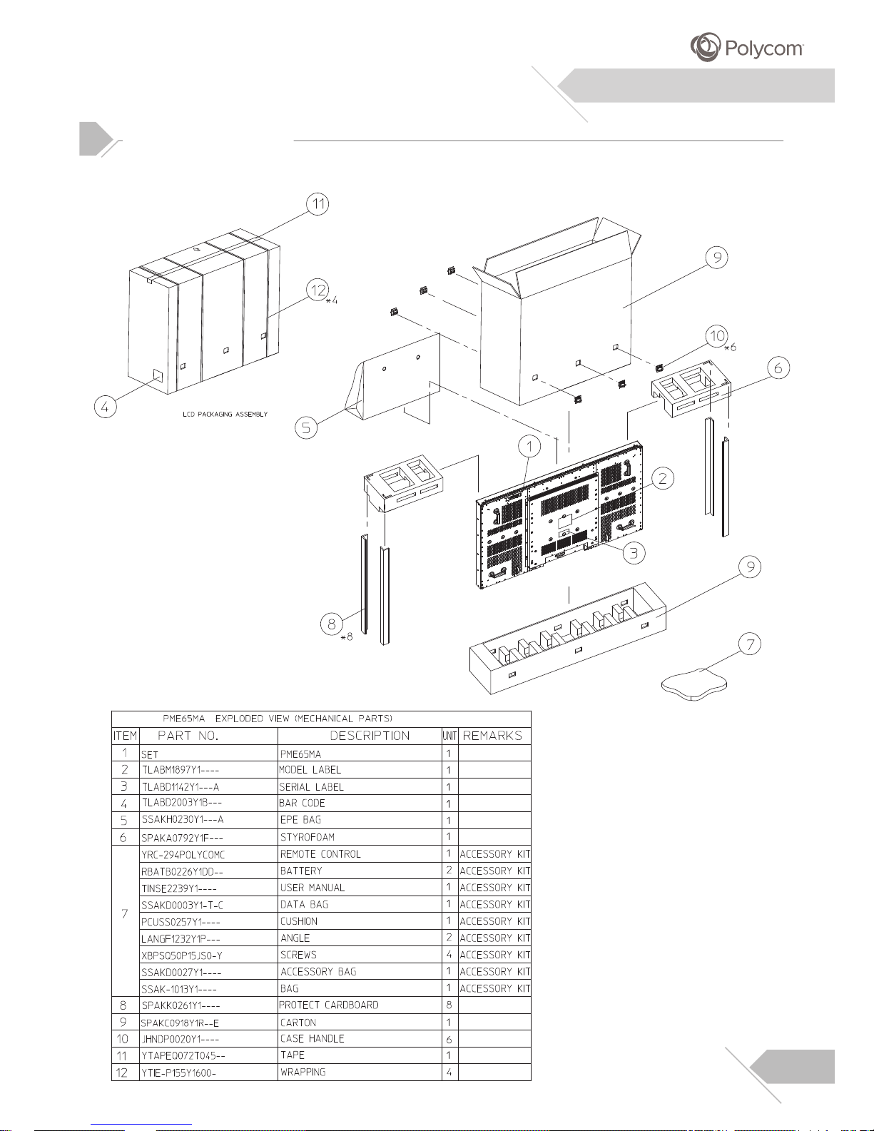
Packing Break Out
26
Page 27
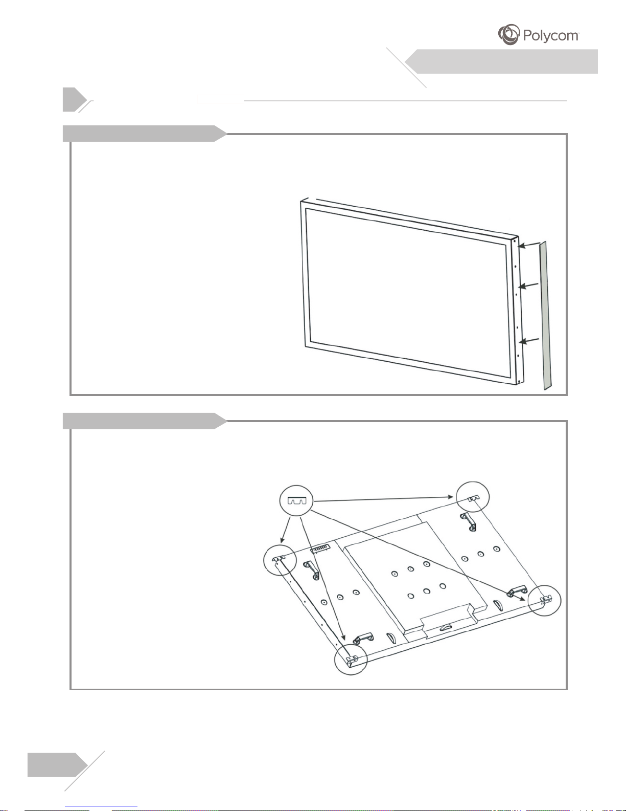
Additional Information
27
Assembly Information
The sponge is applied for eliminating the
gap when jointing 2 displays w ith clips.
Please paste it on the surface of the side
panel as indicated with 5 mm
edge to the front.
The Assembly of Sponge
The Assembly of Clips
Please use the clips to joint 2 panels as
indicated. The clips can be a little bit tight
when apply. Please use the screws to
lock up the clips to the display.
from the
Page 28

TINSE2239Y1----
 Loading...