

Pololu Corporation Zumo 32U4 User Manual
Pololu Zumo 32U4 Robot User’s Guide © 2001–2015 Pololu Corporation
Pololu Zumo 32U4 Robot User’s
Guide
View document on multiple pages. [https://www.pololu.com/docs/0J63]
View this document as a printable PDF: zumo_32u4_robot.pdf [https://www.pololu.com/docs/pdf/0J63/
zumo_32u4_robot.pdf]
https://www.pololu.com/docs/0J63/all Page 1 of 76

Pololu Zumo 32U4 Robot User’s Guide © 2001–2015 Pololu Corporation
1. Overview . . . . . . . . . . . . . . . . . . . . . . . . . . . . . . . . . . . . . . . . . . . . . . . . . . . . 3
1.1. Configurations and included components . . . . . . . . . . . . . . . . . . . . . . . . . . . . . . . 4
1.2. What you will need . . . . . . . . . . . . . . . . . . . . . . . . . . . . . . . . . . . . . . . . . . . 8
1.3. Supported operating systems . . . . . . . . . . . . . . . . . . . . . . . . . . . . . . . . . . . . . 10
2. Contacting Pololu . . . . . . . . . . . . . . . . . . . . . . . . . . . . . . . . . . . . . . . . . . . . . . 11
3. The Zumo 32U4 in detail . . . . . . . . . . . . . . . . . . . . . . . . . . . . . . . . . . . . . . . . . . 12
3.1. Microcontroller . . . . . . . . . . . . . . . . . . . . . . . . . . . . . . . . . . . . . . . . . . . . 12
3.2. User interface . . . . . . . . . . . . . . . . . . . . . . . . . . . . . . . . . . . . . . . . . . . . . 12
3.3. Motors . . . . . . . . . . . . . . . . . . . . . . . . . . . . . . . . . . . . . . . . . . . . . . . . 14
3.4. Quadrature encoders . . . . . . . . . . . . . . . . . . . . . . . . . . . . . . . . . . . . . . . . . 15
3.5. Front sensor array (line and proximity sensors) . . . . . . . . . . . . . . . . . . . . . . . . . . . 17
3.6. Proximity sensing . . . . . . . . . . . . . . . . . . . . . . . . . . . . . . . . . . . . . . . . . . 18
3.7. Inertial sensors . . . . . . . . . . . . . . . . . . . . . . . . . . . . . . . . . . . . . . . . . . . . 21
3.8. Power . . . . . . . . . . . . . . . . . . . . . . . . . . . . . . . . . . . . . . . . . . . . . . . . . 22
3.9. Expansion areas . . . . . . . . . . . . . . . . . . . . . . . . . . . . . . . . . . . . . . . . . . . 23
3.10. Pin assignments . . . . . . . . . . . . . . . . . . . . . . . . . . . . . . . . . . . . . . . . . . . 25
3.11. Adding electronics . . . . . . . . . . . . . . . . . . . . . . . . . . . . . . . . . . . . . . . . . 28
3.12. AVR Timers . . . . . . . . . . . . . . . . . . . . . . . . . . . . . . . . . . . . . . . . . . . . . 30
3.13. Schematics and dimensions . . . . . . . . . . . . . . . . . . . . . . . . . . . . . . . . . . . . . 30
4. Assembling the Zumo 32U4 kit . . . . . . . . . . . . . . . . . . . . . . . . . . . . . . . . . . . . . . . 32
5. Programming the Zumo 32U4 . . . . . . . . . . . . . . . . . . . . . . . . . . . . . . . . . . . . . . . . 60
5.1. Installing Windows drivers . . . . . . . . . . . . . . . . . . . . . . . . . . . . . . . . . . . . . . 60
5.2. Programming using the Arduino IDE . . . . . . . . . . . . . . . . . . . . . . . . . . . . . . . . 62
5.3. Programming using avr-gcc and AVRDUDE . . . . . . . . . . . . . . . . . . . . . . . . . . . . 65
6. Zumo 32U4 Arduino library . . . . . . . . . . . . . . . . . . . . . . . . . . . . . . . . . . . . . . . . . 67
7. The Zumo 32U4 USB interface . . . . . . . . . . . . . . . . . . . . . . . . . . . . . . . . . . . . . . . 68
8. The A-Star 32U4 Bootloader . . . . . . . . . . . . . . . . . . . . . . . . . . . . . . . . . . . . . . . . 70
9. Reviving an unresponsive Zumo 32U4 . . . . . . . . . . . . . . . . . . . . . . . . . . . . . . . . . . . 73
9.1. Reviving using the Arduino IDE . . . . . . . . . . . . . . . . . . . . . . . . . . . . . . . . . . . 73
9.2. Reviving using AVRDUDE . . . . . . . . . . . . . . . . . . . . . . . . . . . . . . . . . . . . . 75
10. Related resources . . . . . . . . . . . . . . . . . . . . . . . . . . . . . . . . . . . . . . . . . . . . . . 76
Page 2 of 76
Pololu Zumo 32U4 Robot User’s Guide © 2001–2015 Pololu Corporation
1. Overview
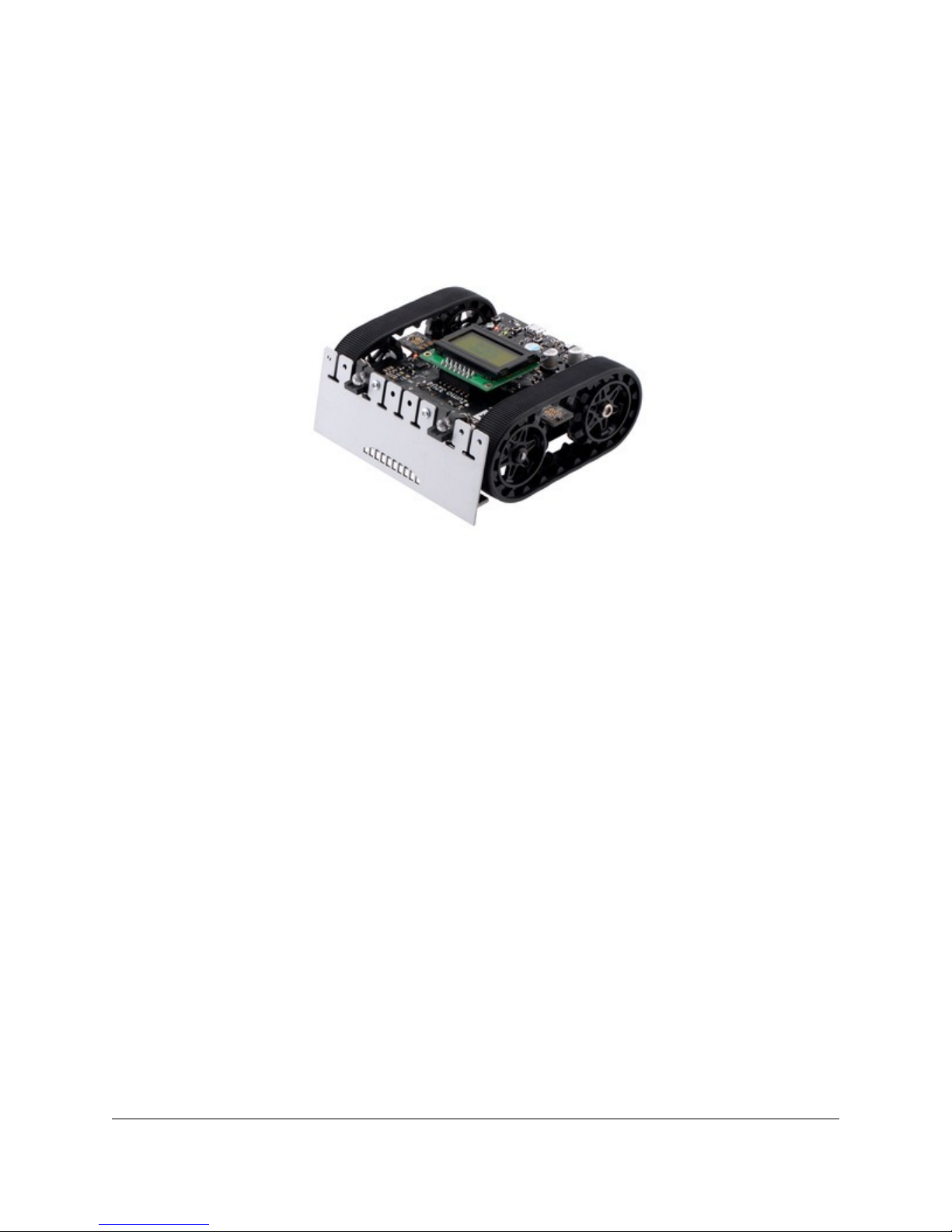
The Zumo 32U4 robot is a complete, versatile robot controlled by an Arduino-compatible ATmega32U4
microcontroller. When assembled, the low-profile tracked robot measures less than 10 cm on each side, making
it suitable for Mini-Sumo competitions.
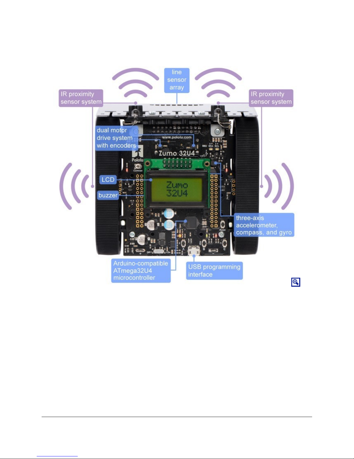
At the heart of the Zumo 32U4 is an integrated ATmega32U4 AVR microcontroller from Atmel, along with dual
H-bridge drivers that power the robot’s motors. The robot also features a variety of sensors, including quadrature
encoders and inertial sensors (accelerometer and gyro) on the main board, along with reflectance and proximity
sensors on the front sensor array. On-board pushbuttons offer a convenient interface for user input, and an LCD,
buzzer, and indicator LEDs allow the robot to provide feedback.
Like our A-Star 32U4 programmable controllers [https://www.pololu.com/category/149/a-star-programmable-
controllers], the Zumo 32U4 features a USB interface and ships preloaded with an Arduino-compatible bootloader.
We provide a software add-on that makes it easy to program the Zumo 32U4 from the Arduino environment, as
well as a set of Arduino libraries to help interface with its on-board hardware.
1. Overview Page 3 of 76
Pololu Zumo 32U4 Robot User’s Guide © 2001–2015 Pololu Corporation
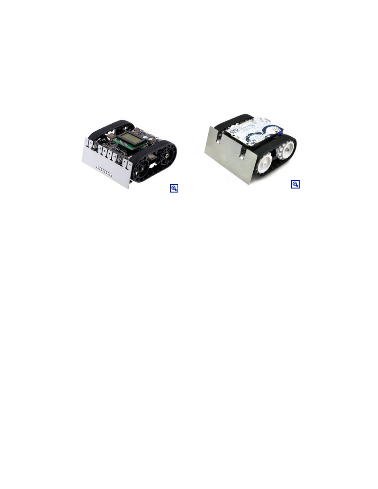
Comparison with the Zumo robot kit for Arduino (with Zumo Shield)
Our older Zumo robot for Arduino [https://www.pololu.com/product/2510], built with a Zumo Shield
[https://www.pololu.com/product/2508], is another Arduino-compatible robotic platform based on the Zumo chassis.
The Zumo Shield is designed for a board with a standard Arduino form factor, like an Arduino Uno
[https://www.pololu.com/product/2191], Arduino Leonardo [https://www.pololu.com/product/2192], or A-Star 32U4
Prime [https://www.pololu.com/category/165/a-star-32u4-prime], to plug into it and act as its controller.
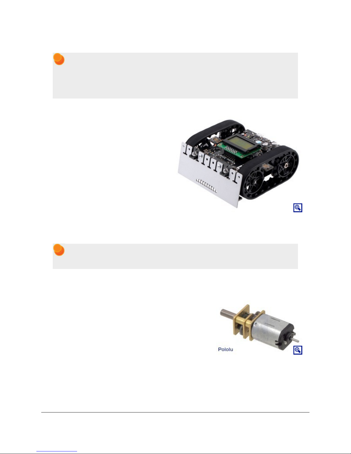
Assembled Zumo 32U4 robot.
Assembled Zumo robot for Arduino
with an Arduino Uno (with original
white sprockets).
By contrast, the Zumo 32U4 includes an on-board ATmega32U4 microcontroller (the same one used in the
Leonardo and A-Star 32U4 boards), combining the functions of the Zumo Shield and the separate Arduino
controller into a single board and enabling the resulting robot to be even more compact. However, it remains
just as easy to program as a standard Arduino, thanks to its USB interface and preloaded Arduino-compatible
bootloader. The Zumo 32U4 also adds many features that are not found on the Zumo Shield, including encoders,
an LCD, and proximity detection.
Some of the pin mappings and software libraries differ between the Zumo 32U4 and Zumo robot for Arduino,
so programs written for one robot generally need to be modified to work on the other.
1.1. Configurations and included components
The Zumo 32U4 robot is available in several configurations:
• Zumo 32U4 Robot Kit (No Motors) [https://www.pololu.com/product/3124] – requires assembly and
soldering; can be customized with your choice of motors [https://www.pololu.com/category/60/micro-metal-
gearmotors] (not included)
• Zumo 32U4 Robot (assembled with 50:1 HP motors) [https://www.pololu.com/product/3125]
• Zumo 32U4 Robot (assembled with 75:1 HP motors) [https://www.pololu.com/product/3126]
• Zumo 32U4 Robot (assembled with 100:1 HP motors) [https://www.pololu.com/product/3127]
1. Overview Page 4 of 76
Pololu Zumo 32U4 Robot User’s Guide © 2001–2015 Pololu Corporation
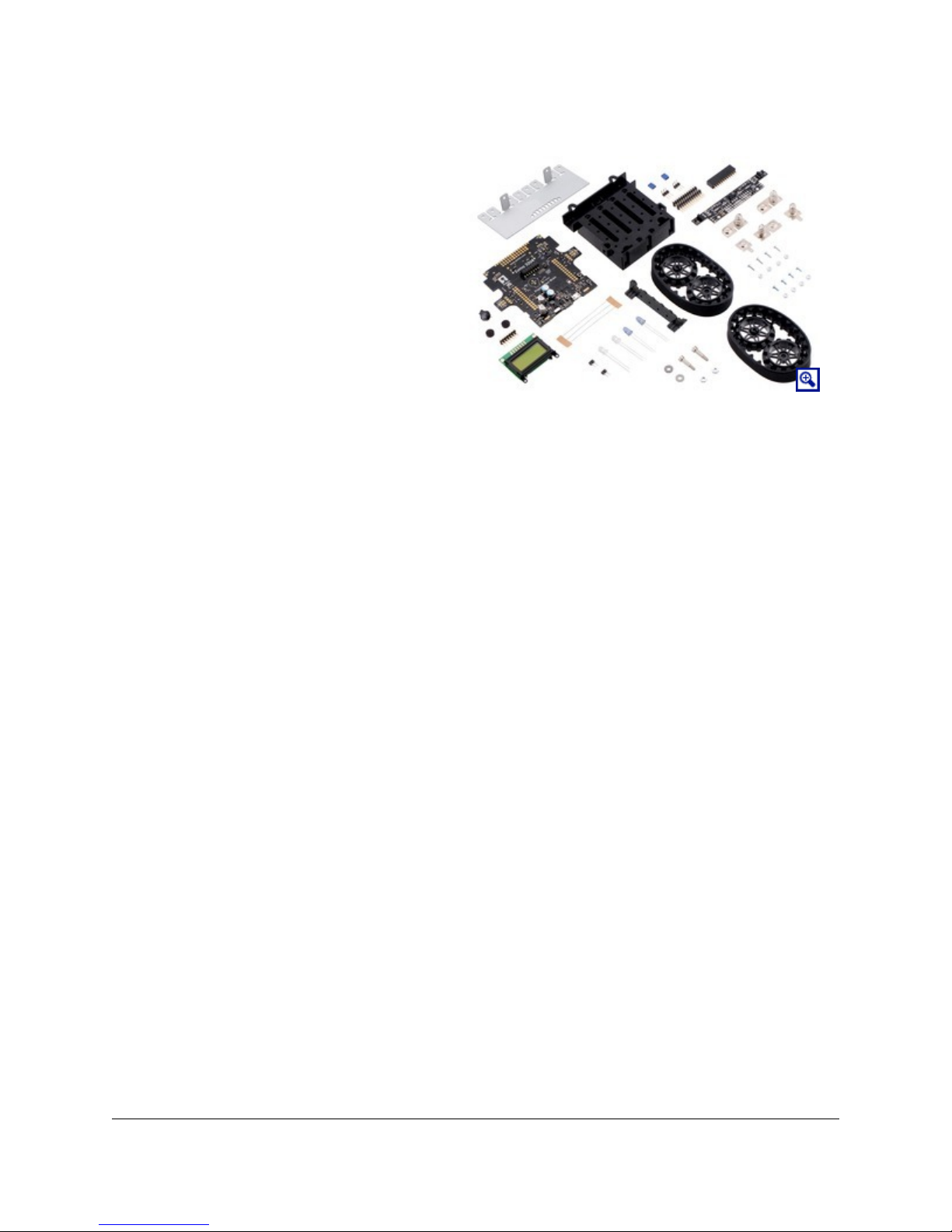
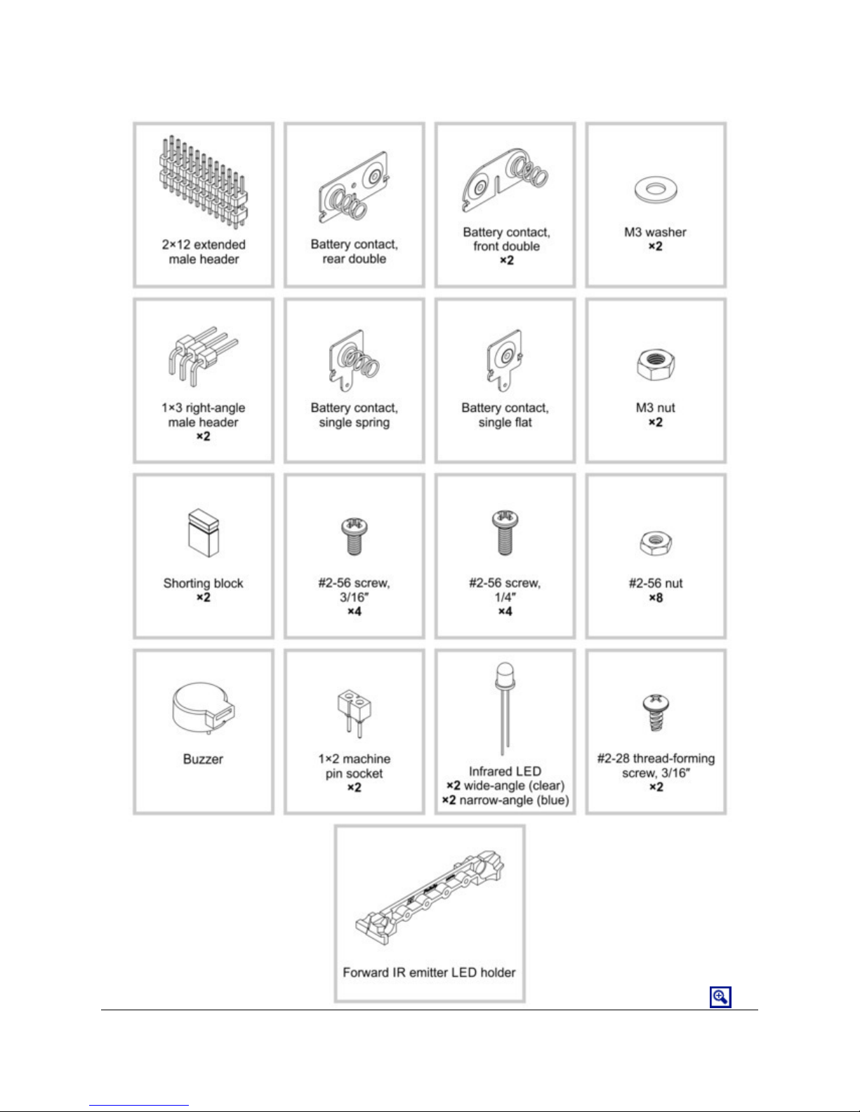
Zumo 32U4 robot kit contents
The kit version of the Zumo 32U4 robot includes
the following items:
• Zumo 32U4 main board and associated
hardware:
◦ two wide-angle and two narrow-angle
through-hole infrared LEDs
◦ two 1×2 machine pin sockets for IR LEDs
◦ forward IR emitter LED holder
◦ two 3/16″ #2-28 thread-forming screws for
LED holder
◦ buzzer [https://www.pololu.com/product/1484]
◦ 8×2 character LCD [https://www.pololu.com/product/356]
◦ 2×7 low-profile male header [https://www.pololu.com/product/2663] for LCD
◦ jumper wires (for soldering motors to the main board)
◦ two magnetic encoder discs [https://www.pololu.com/product/2599] (12 CPR)
• Zumo 32U4 front sensor array and associated hardware:
◦ 2×12 female header and 2×12 extended male header for sensor array
◦ two 1×3 right-angle male headers and two shorting blocks – jumpers for sensor array
• Zumo chassis kit [https://www.pololu.com/product/1418], which includes:
◦ Zumo chassis main body
◦ two drive sprockets
◦ two idler sprockets
◦ two 22-tooth silicone tracks
◦ two shoulder bolts with washers and M3 nuts
◦ four 1/4″ #2-56 screws and nuts
◦ battery terminals
• Zumo 32U4 blade
• four 3/16″ #2-56 screws
• four additional #2-56 machine nuts (for a total of eight)
1. Overview Page 5 of 76

Pololu Zumo 32U4 Robot User’s Guide © 2001–2015 Pololu Corporation
1. Overview Page 6 of 76
Pololu Zumo 32U4 Robot User’s Guide © 2001–2015 Pololu Corporation
1. Overview Page 7 of 76
Pololu Zumo 32U4 Robot User’s Guide © 2001–2015 Pololu Corporation
The robot and chassis kit might include extra parts like jumper wires, screws, nuts, washers, and
an acrylic spacer plate (which is not used in the Zumo 32U4), so do not be concerned if you have
some leftover hardware after assembling your Zumo. Your kit might also include a length of heat
shrink tubing that can be used as shrouds for IR LEDs. Kits shipped before August 2015 include
heat shrink tubing but do not include the LED holder and its mounting screws.
Assembled Zumo 32U4 robot
The Zumo 32U4 robot is a complete, ready-toprogram robot platform built from the same
components found in the Zumo 32U4 Robot Kit; no
soldering or assembly is required. A choice of three
motor gear ratios offer different combinations of
torque and speed.
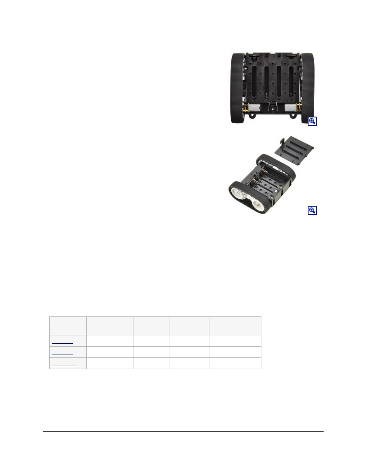
Different versions of the assembled Zumo 32U4
robots can be identified with a sticker on the
underside of the main board, visible inside the
battery compartment of the Zumo without batteries
installed. The color of the sticker indicates the gear
ratio of the robot’s motors:
• Green: 50:1 HP
• Blue: 75:1 HP
• Red: 100:1 HP
The assembled Zumo 32U4 robot is fitted with wide-angle IR emitter LEDs (clear); the narrowangle LEDs (blue) are not included.
1.2. What you will need
These additional items are needed for using the Zumo 32U4 robot:
Micro metal gearmotor with
extended motor shaft.
1. Overview Page 8 of 76
Pololu Zumo 32U4 Robot User’s Guide © 2001–2015 Pololu Corporation
• Four AA batteries. The robot works with both alkaline and NiMH
batteries, though we recommend using rechargeable AA NiMH cells
[https://www.pololu.com/product/1003].
• USB A to Micro-B cable [https://www.pololu.com/product/2072] to
connect the robot to your computer for programming and debugging.
• Small 2 mm slotted screwdriver for adjusting the LCD contrast.
In addition, the kit version of the robot requires:
• Two micro metal gearmotors with extended motor shafts (see
below).
Kit motor selection
The kit version of the Zumo 32U4 robot requires the addition of two (2)
micro metal gearmotors with extended motor shafts, one for each
tread.
The ideal motors for your robot depend on your desired torque, speed,
and current draw. We generally recommend using HP versions of our
micro metal gearmotors since the tracks require a decent amount of
torque to move effectively; higher gear ratios of the non-HP motors
might work if you want lower current draw, but they will be slower and
offer less control.
If you are unsure which motors to choose, we recommend getting two of the 75:1 Micro Metal Gearmotor
HP with Extended Motor Shaft [https://www.pololu.com/product/2215], which offer a good balance of performance
characteristics, and most of our example code was developed and tested with these motors. 50:1 HP
[https://www.pololu.com/product/2213] and 100:1 HP [https://www.pololu.com/product/2215] motors also generally work
well. These three motor types are the ones we offer in assembled Zumo 32U4 robots.
The following table summarizes the key specifications of the recommended 50:1 HP, 75:1 HP, and 100:1
HP motors. The first four columns are specifications of the motors themselves, while the last column is the
measured top speed of a Zumo chassis loaded to a weight of 500 g and driven with these motors. Note that the
specifications are for 6V operation, which is approximately the voltage you would get with four fresh alkaline
batteries; four NiMH AA cells will typically provide less than 5V.
Micro Metal
Gearmotor
Free-Run Speed
@ 6V
Stall Torque
@ 6V
Stall Current
@ 6V
Top Zumo Speed
@ 6V and 500g
50:1 HP 625 RPM 15 oz·in 1600 mA 40 in/s (100 cm/s)
75:1 HP 400 RPM 22 oz·in 1600 mA 25 in/s (65 cm/s)
100:1 HP 320 RPM 30 oz·in 1600 mA 20 in/s (50 cm/s)
For more options, you can see our other micro metal gearmotors with extended motor shafts
[https://www.pololu.com/category/141/micro-metal-gearmotors-with-extended-motor-shafts]. Be sure to pick a motor that has
an extended shaft, or else you will not be able to use the encoders on the Zumo 32U4.
1. Overview Page 9 of 76

Pololu Zumo 32U4 Robot User’s Guide © 2001–2015 Pololu Corporation
Kit assembly tools
These additional items are needed for assembling the Zumo 32U4 robot kit:
• Soldering iron and solder (we recommend one with adjustable temperature control)
• Wire cutter
• Small #1 Phillips screwdriver
• 3 mm Allen wrench (hex key)
• long-nose pliers (for bending the IR LED leads and Zumo 32U4 blade mounting tabs)
• tape or small clamps (for holding parts together when soldering)
Additional optional components
You might also consider getting these for your Zumo 32U4 robot:
• Sensors [https://www.pololu.com/category/7/sensors], such as optical [https://www.pololu.com/category/79/optical-
range-finders] or sonar range finders [https://www.pololu.com/category/78/sonar-range-finders] (the Zumo 32U4
already has built-in IR proximity sensors, but additional sensors can be incorporated for increased range or
detection area)
• Connectors and jumper wires [https://www.pololu.com/category/19/connectors], for connecting additional
sensors and components
• Battery charger, if you are using rechargeable batteries; since the Zumo just uses ordinary AA batteries,
we recommend basic AA chargers (into which you stick the individual cells) available at most general
electronics stores, though we carry a much fancier iMAX-B6AC V2 balance charger/discharger
[https://www.pololu.com/product/2588] that can be also used for this
1.3. Supported operating systems
The Zumo 32U4 robot can be programmed from a computer using any operating system that supports the
Arduino environment. This includes Microsoft Windows 10, 8.1, 8, 7, Vista, XP (with Service Pack 3), Linux,
and Mac OS X.
1. Overview Page 10 of 76

Pololu Zumo 32U4 Robot User’s Guide © 2001–2015 Pololu Corporation
2. Contacting Pololu
We would be delighted to hear from you about your experiences with the Zumo 32U4 robot. If you need technical
support or have any feedback you would like to share, you can contact us [https://www.pololu.com/contact] directly
or post on our forum [http://forum.pololu.com/viewforum.php?f=29]. Tell us what we did well, what we could improve,
what you would like to see in the future, or anything else you would like to say!
2. Contacting Pololu Page 11 of 76

Pololu Zumo 32U4 Robot User’s Guide © 2001–2015 Pololu Corporation
3. The Zumo 32U4 in detail
3.1. Microcontroller
The Zumo 32U4 main board features an integrated, USB-enabled ATmega32U4 AVR microcontroller from
Atmel, clocked by a precision 16 MHz crystal oscillator. This is the same microcontroller and clock frequency
used in our family of A-Star 32U4 programmable controllers [https://www.pololu.com/category/149/a-star-
programmable-controllers], as well as the Arduino Leonardo [https://www.pololu.com/product/2192] and Micro
[https://www.pololu.com/product/2188].
The main board includes a USB Micro-B connector that can be used to connect to a computer’s USB port via
a USB A to Micro-B cable [https://www.pololu.com/product/2072] (not included). The USB connection can be used
to transmit and receive data from the computer and program the board over USB. The USB connection also
provides power for the microcontroller and most of the other hardware on the Zumo (but not motor power); see
Section 3.8 for more details.
The Zumo’s ATmega32U4 comes preloaded with the same Arduino-compatible USB bootloader as the AStar 32U4, which allows it to be easily programmed using the Arduino IDE. For more information about
programming the Zumo 32U4, see Section 5. The ATmega32U4 might also come preloaded with a simple
program that blinks the yellow LED and writes “Zumo 32U4” to the LCD.
3.2. User interface
LEDs
The Zumo 32U4 has eight indicator LEDs.
• A yellow user LED is connected to Arduino digital pin 13, or PC7. You can drive this pin high in a user
program to turn this LED on. The Zumo’s A-Star 32U4 Bootloader [https://www.pololu.com/docs/0J61/9] fades
this LED on and off while it is waiting for a sketch to be loaded.
• A green user LED is connected to PD5 and lights when the pin is driven low. While the board is running
the A-Star 32U4 Bootloader or a program compiled in the Arduino environment, it will flash this LED
when it is transmitting data via the USB connection.
• A red user LED is connected to Arduino pin 17, or PB0, and lights when the pin is driven low. While
the board is running the A-Star 32U4 Bootloader or a program compiled in the Arduino environment, it will
flash this LED when it is receiving data via the USB connection.
3. The Zumo 32U4 in detail Page 12 of 76

Pololu Zumo 32U4 Robot User’s Guide © 2001–2015 Pololu Corporation
The Zumo32U4 library [https://www.pololu.com/docs/0J63/6] contains functions that make it easier to control the
three user LEDs. All three user LED control lines are also LCD data lines, so you will see them flicker when you
update the LCD. The green and red user LEDs also share I/O lines with pushbuttons (see below).
• Two red LEDs on the left and right edges of the board indicate when the robot’s infrared emitters are
active on the corresponding side.
• Two blue power LEDs under the rear corners of the main board indicate when the robot is receiving
power from batteries (the power switch must be turned on). The left LED is connected to the reverseprotected and switched battery voltage (VBAT), while the right LED is connected to the output of the main
board’s 5 V regulator.
The left blue LED will become noticeably dimmer as the total battery voltage drops below about
3 V, and this can serve as an indication that a set of alkaline batteries has reached the end of
its useful life. However, rechargeable batteries can be damaged by overdischarge, so we do not
recommend allowing a set of four NiMH cells to discharge to this point. (A voltage divider is
connected to analog pin 1 and can be used to monitor the battery voltage; see Section 3.8 for
details.)
• A green power LED under the center rear edge of the main board indicates when the USB bus voltage
(VBUS) is present.
Pushbuttons
The Zumo 32U4 has four pushbuttons: a reset button on the right edge and three user pushbuttons located
along the rear edge of the main board. The user pushbuttons, labeled A, B, and C, are on Arduino pin 14 (PB3),
PD5, and Arduino pin 17 (PB0), respectively. Pressing one of these buttons pulls the associated I/O pin to ground
through a resistor.
The three buttons’ I/O lines are also used for other purposes: pin 14 is MISO on the SPI interface, PD5 and pin
17 control the green and red user LEDs, and all three pins are LCD data lines. Although these uses require the
pins to be driven by the AVR (or SPI slave devices in the case of MISO), resistors in the button circuits ensure
that the Zumo will not be damaged even if the corresponding buttons are pressed at the same time, nor will SPI
or LCD communications be disrupted. The functions in the Zumo32U4 library [https://www.pololu.com/docs/0J63/6]
take care of configuring the pins, reading and debouncing the buttons, and restoring the pins to their original
states.
LCD
The Zumo 32U4 has a 2×7 header where you can connect the included 8×2 character LCD
[https://www.pololu.com/product/356] (or any other LCD with the common HD44780 parallel interface
[https://www.pololu.com/file/download/DMC50448N-AAE-AD.pdf?file_id=0J71] (109k pdf)). You can adjust the LCD
contrast with the potentiometer to the left of the LCD connector. We recommend using a 2 mm slotted
screwdriver to adjust the contrast.
The Zumo32U4 library [https://www.pololu.com/docs/0J63/6] provides functions to display data on a connected
LCD. It is designed to gracefully handle alternate use of the LCD data lines by only changing pin states when
needed for an LCD command, after which it will restore them to their previous states. This allows the LCD data
lines to be used for other functions (such as pushbutton inputs and LED drivers).
3. The Zumo 32U4 in detail Page 13 of 76

Pololu Zumo 32U4 Robot User’s Guide © 2001–2015 Pololu Corporation
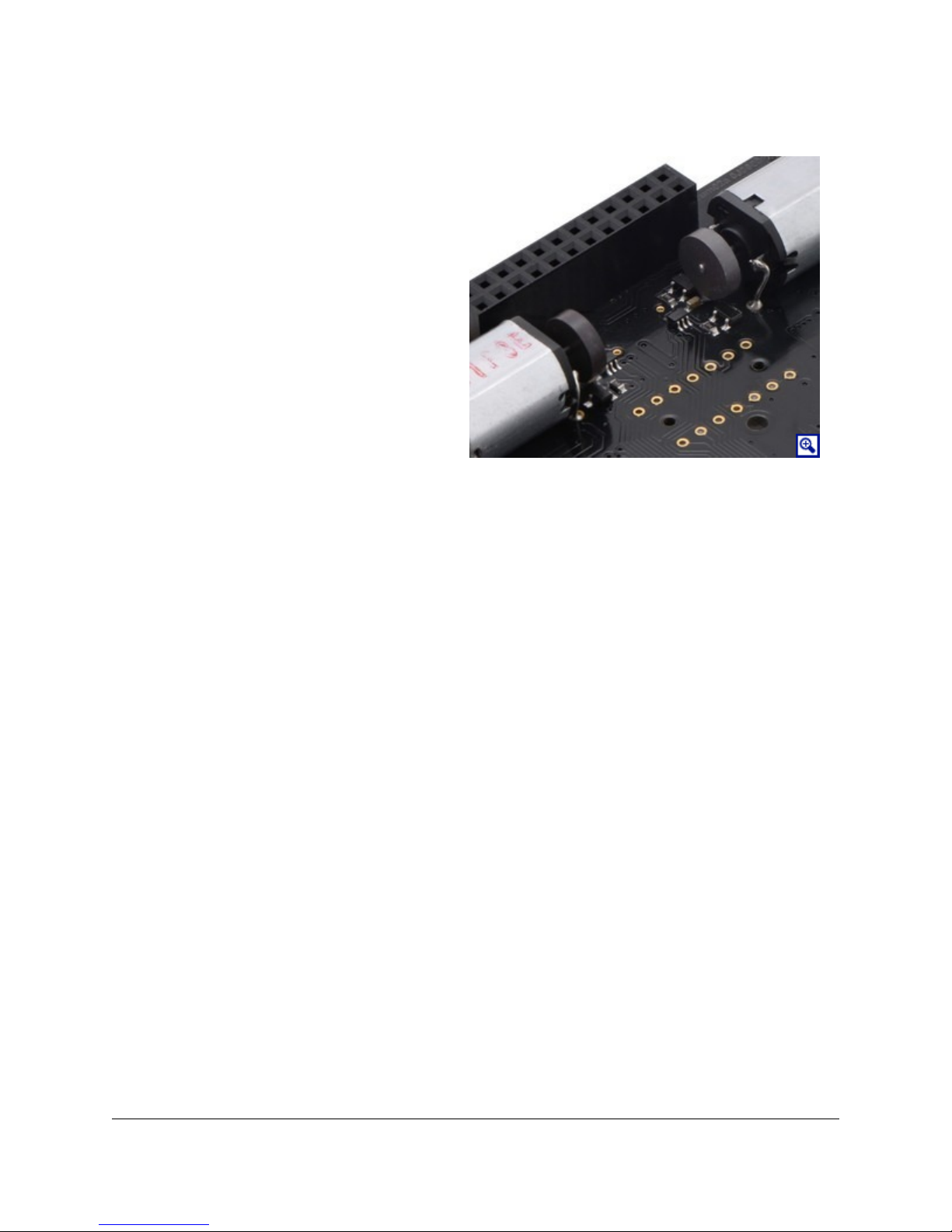
Buzzer
The buzzer [https://www.pololu.com/product/1484] on the Zumo 32U4 can be used to generate simple sounds and
music. By default, it is connected to digital pin 6 (which also serves as OC4D, a hardware PWM output from
the AVR’s 10-bit Timer4). If you alternate between driving the buzzer pin high and low at a given frequency, the
buzzer will produce sound at that frequency. You can play notes and music with the buzzer using functions in
the Zumo32U4Buzzer library. If you want to use pin 6 for an alternate purpose, you can disconnect the buzzer
circuit by cutting the surface-mount jumper next to the buzzer.
3.3. Motors
Two on-board Texas Instruments DRV8838 motor drivers power the Zumo 32U4’s two micro metal gearmotors.
Four Arduino pins are used to control the drivers:
• Digital pin 15, or PB1, controls the right motor direction (LOW drives the motor forward, HIGH
drives it in reverse).
• Digital pin 16, or PB2, controls the left motor direction.
• Digital pin 9, or PB5, controls the right motor speed with PWM (pulse width modulation) generated
by the ATmega32U4’s Timer1.
• Digital pin 10, or PB6, controls the left motor speed with PWM.
For more information about the drivers, see the DRV8838 datasheet [https://www.pololu.com/file/download/
drv8838.pdf?file_id=0J806] (1MB pdf). We also sell a carrier board [https://www.pololu.com/product/2990] for this
driver.
The Zumo32U4 library [https://www.pololu.com/docs/0J63/6] provides functions that allow you to easily control the
motors, and it can optionally take care of flipping a direction signal for you if you accidentally soldered in a
motor backwards.
As your batteries run out, the voltage supplied to the motor drivers (VBAT) will decrease, which
will make the motors slower. It is possible to account for this in your code by monitoring the
battery voltage (see Section 3.8) or using the encoders and other sensors to monitor the movement
of the robot.
3. The Zumo 32U4 in detail Page 14 of 76
Pololu Zumo 32U4 Robot User’s Guide © 2001–2015 Pololu Corporation
3.4. Quadrature encoders
Each drive motor on the Zumo 32U4 has a
corresponding quadrature encoder system consisting
of a magnetic disc attached to the extended motor
shaft and a pair of Hall effect sensors mounted to the
underside of the main board. Other than the sensor
orientation, these encoders work similarly to our
magnetic encoder kits for micro metal
gearmotors [https://www.pololu.com/product/2598].
They can be used to track the rotational speed and
direction of the robot’s drive sprockets.
The encoders provide a resolution of 12 counts per
revolution of the motor shaft when counting both
edges of both channels. To compute the counts per
revolution of the drive sprockets, multiply the
gearboxes’ gear ratio by 12. For example, if 75:1
motors [https://www.pololu.com/product/2215] (which
have gear ratios more accurately specified as
75.81:1) are used, the encoders provide 75.81 × 12 ≈ 909.7 CPR.
Quadrature encoder transitions are often detected by monitoring both encoder channels directly. However, since
transitions on the Zumo’s encoders can occur at high frequencies (several thousand per second) when its motors
are running, it is necessary to use the AVR’s pin change interrupts or external interrupts to read the encoders. To
reduce the required number of interrupt pins, the Zumo 32U4 main board XORs together both channels of each
encoder and connects the resulting signal to an interrupt pin, while channel B of each encoder is connected to a
non-interrupt pin:
• Digital pin 7, or PE6, reads the right encoder XORed signal using external interrupt INT6.
• Digital pin 8, or PB4, reads the left encoder XORed signal using pin change interrupt PCINT4.
• Digital pin 23 (analog pin 5), or PF0, reads the right encoder channel B.
• Pin PE2 reads the left encoder channel B.
3. The Zumo 32U4 in detail Page 15 of 76

Pololu Zumo 32U4 Robot User’s Guide © 2001–2015 Pololu Corporation
The XORed signal and the channel B signal can be used to reconstruct the channel A signal by simply XORing
them again: (A XOR B) XOR B = A. For both encoders, channel A leads channel B when the motor is rotating
in the forward direction; that is, A rises before B rises and A falls before B falls. (The waveforms in the diagram
above would be produced by forward rotation.)
The Zumo 32U4 library [https://www.pololu.com/docs/0J63/6] provides appropriate interrupt service routines and
functions for reading the encoders and keeping track of their counts.
3. The Zumo 32U4 in detail Page 16 of 76

Pololu Zumo 32U4 Robot User’s Guide © 2001–2015 Pololu Corporation
3.5. Front sensor array (line and proximity sensors)
The Zumo 32U4 Front Sensor Array is a separate
board that attaches to the main board. The board
features five line sensors and three proximity
sensors, though by default, you can only have six of
these eight sensors connected to the Zumo’s
microcontroller at any given time.
The five line sensors face downward and can help
the Zumo distinguish between light and dark
surfaces. They can also be used to detect sources of
infrared light, like the sun. Each reflectance sensor
consists of a down-facing infrared (IR) emitter LED
paired with a phototransistor that can detect
reflected infrared light from the LED. The
reflectance sensors operate on the same principles as
our QTR-1RC [https://www.pololu.com/product/2459]
sensor: the AVR uses an I/O line to drive the sensor
output high, and then measures the time for the
output voltage to decay. The IR emitters for the
reflectance sensors are on by default, but they can be
turned off by driving digital pin 11 low. The five line sensors are numbered 1 through 5, with line sensor 1 being
the robot’s left-most sensor. In schematics and diagrams, they are referred to as DOWN1, DOWN2, DOWN3,
DOWN4, and DOWN5. On the front sensor array, their signals are labeled DN1, DN2, DN3, DN4, and DN5. The
part used for the line sensors is the Sharp GP2S60 compact reflective photointerrupter
[https://www.pololu.com/file/download/GP2S60_DS.pdf?file_id=0J683] (164k pdf).
The three proximity sensors face in different directions away from the Zumo and can help detect nearby objects.
They can also be used to detect commands from typical IR remote controls. The proximity sensors, like the line
sensors, detect reflected IR light, but they are designed to only detect light that is turned on and off quickly at a
frequency of 38 kHz. To read a proximity sensor, the AVR can enable the internal pull-up on the corresponding
I/O line. When the sensor is active, it will drive the line low. The proximity sensors do not have IR emitters
paired with them; instead they detect reflected 38 kHz IR light that comes from LEDs on the Zumo 32U4 Main
Board, which are described in Section 3.6. The proximity sensors are named after the directions they face: left,
right, or front. In schematics and diagrams, they are referred to as LEFT, RIGHT, and FRONT. On the front
sensor array, their signals are labeled LFT, FRONT, and RGT. The part used for the proximity sensors is the
Vishay TSSP77038 IR receiver module [https://www.pololu.com/file/download/tssp77038.pdf?file_id=0J615] (268k pdf).
The TSSP77038 has a fixed gain (sensitivity) that makes the sensor more predictable.
Each sensor output on the front sensor array is protected by a 220 Ohm resistor to help prevent short circuits
when the AVR is driving the corresponding I/O line.
The infrared emitted by the line sensors can interfere with the proximity sensors and cause false readings,
so it is recommended to turn off the line sensor emitters before using the proximity sensors. The
Zumo32U4ProximitySensors class from the Zumo 32U4 Arduino library takes care of turning off the line sensor
emitters.
Pin assignments
By default, the front sensor array supports these pin assignments:
3. The Zumo 32U4 in detail Page 17 of 76

Pololu Zumo 32U4 Robot User’s Guide © 2001–2015 Pololu Corporation
• Pin A0 (18) is connected to line sensor 1 (DN1),
• Pin A3 (21) is connected to line sensor 3 (DN3).
• Pin 12 is connected to line sensor 5 (DN5).
• Pin A4 (22) is connected to the front proximity sensor.
• Pin A2 (20) is connected to either the left proximity sensor (LFT) or line sensor 2 (DN2), depending on
the position of a jumper.
• Pin 4 is connected to either the right proximity sensor (RGT) or line sensor 4 (DN4), depending on the
position of a jumper.
• Pin 11 is connected to the line sensor emitter control pin (LEDON).
The assembled versions of the Zumo 32U4 robot ship with jumpers selecting the left (LFT)
and right (RGT) proximity sensors instead of down-facing DN2 and DN4, so these versions are
configured for three down-facing sensors and all three proximity sensors by default.
The signals from the sensors can be remapped by soldering in a wire from the signal output to the desired I/O
pin. You would also want to disconnect the sensor output from the standard I/O pin so that pin can be used for
other purposes. For line sensor 1, line sensor 3, line sensor 5, and the front proximity sensor, disconnecting the
sensor involves cutting a trace between the signal output and the standard I/O pin, which is labeled on the board.
For the line sensor 2, line sensor 4, the left proximity sensor, and the right proximity sensor, you can simply
move or remove the corresponding jumper.
Example remapping: using all the sensors
If you want to use all five line sensors and all three proximity sensors in one application, you can accomplish
that by freeing up two I/O lines and remapping two of the pins. One way to accomplish this is by removing the
Zumo’s LCD to free up pins 0 and 1. Next, configure the jumpers on the front sensor array to connect pin 4
to line sensor 4, and pin 20 to line sensor 2. Solder a wire from the right proximity sensor signal to pin 0, and
solder a wire from the left proximity sensor to pin 1. You will need to modify your code to include the new pin
assignments, and you should remove all LCD-related code.
3.6. Proximity sensing
The Zumo 32U4 can detect nearby objects using the three proximity sensors on the front sensor array. The
proximity sensors do not emit their own light; instead they are designed to detect 38 kHz infrared (IR) signals
from emitters on the Zumo 32U4 Main Board.
The main board has four IR emitters:
• The middle-left and middle-right IR LEDs are surface-mounted on either side of the Zumo, inside the
tracks and between the wheels. They emit light to the left and to the right.
• The front-left and front-right IR LEDs are meant to face towards the front, though you can play with the
exact angle to see if it yields better results for your particular application. These LEDs are included, but
they must be installed by the user, as described in Section 4.
3. The Zumo 32U4 in detail Page 18 of 76
Pololu Zumo 32U4 Robot User’s Guide © 2001–2015 Pololu Corporation
The middle-left LED and the front-left LED are in series, so you must install the front-left LED
in order to use the middle-left LED, and you cannot turn on one without turning on the other.
Similarly, the middle-right and front-right IR emitters are in series.
Two AVR pins are used to control the LEDs: pin 5 (OC3A) is the proximity LED PWM pin, and must be driven
high to turn on any of the LEDs. Pin A1 (19) is the proximity LED selection pin, and must be driven high or
low to select which set of LEDs to turn on. If A1 is high, the right-side LEDs are selected. If A1 is low, the
left-side LEDs are selected. (When A1 is an input, it can be used to read the battery voltage.) The brightness of
the emitters can be controlled by adjusting the duty cycle of the PWM signal on pin 5.
Our example code operates the proximity sensors by transmitting pulses on both the left and right LEDs at six
different brightness levels. For each sensor, it generates two numbers: the number of brightness levels for the
left LEDs that activated the sensor, and the number of brightness levels for the right LEDs that activated the
sensor. A higher reading corresponds to more IR light getting reflected to the sensor, which is influenced by the
size, reflectivity, proximity, and location of nearby objects. However, the presence of other sources of 38 kHz IR
pulses (e.g. from another robot) can also affect the readings.
You can also just read the proximity sensors without turning on any LEDs. This could allow the Zumo to detect
the IR proximity sensors of other robots, or to detect commands from a typical IR remote.
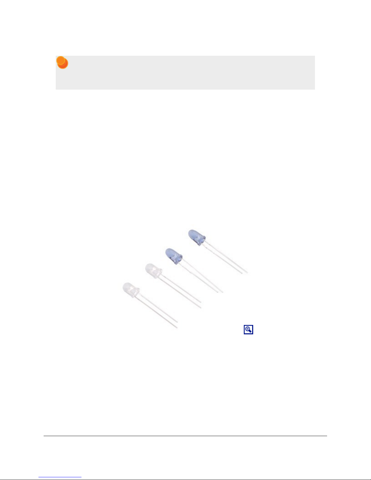
Forward LED selection
The kit version of the Zumo 32U4 comes with two types of through-hole IR LEDs that can be installed to
serve as the forward emitters. Both types of LEDs use the T-1 3/4 package, meaning they have a diameter
of approximately 5 mm. Also, they both emit 940 nm light. The main difference between these LEDs is their
viewing angle. The blue-colored LEDs have a relatively narrow viewing angle of 20°, which makes them better
at illuminating objects far away. The clear LEDs have a much wider 50° viewing angle, which makes them better
at illuminating objects that are not directly in front of the Zumo. The choice of IR LEDs to use is one way for
you to customize your Zumo.
The assembled versions of the Zumo 32U4 robot ship with clear (wide-angle) LEDs installed; blue (narrowangle) LEDs are not included with these versions.
3. The Zumo 32U4 in detail Page 19 of 76
Pololu Zumo 32U4 Robot User’s Guide © 2001–2015 Pololu Corporation
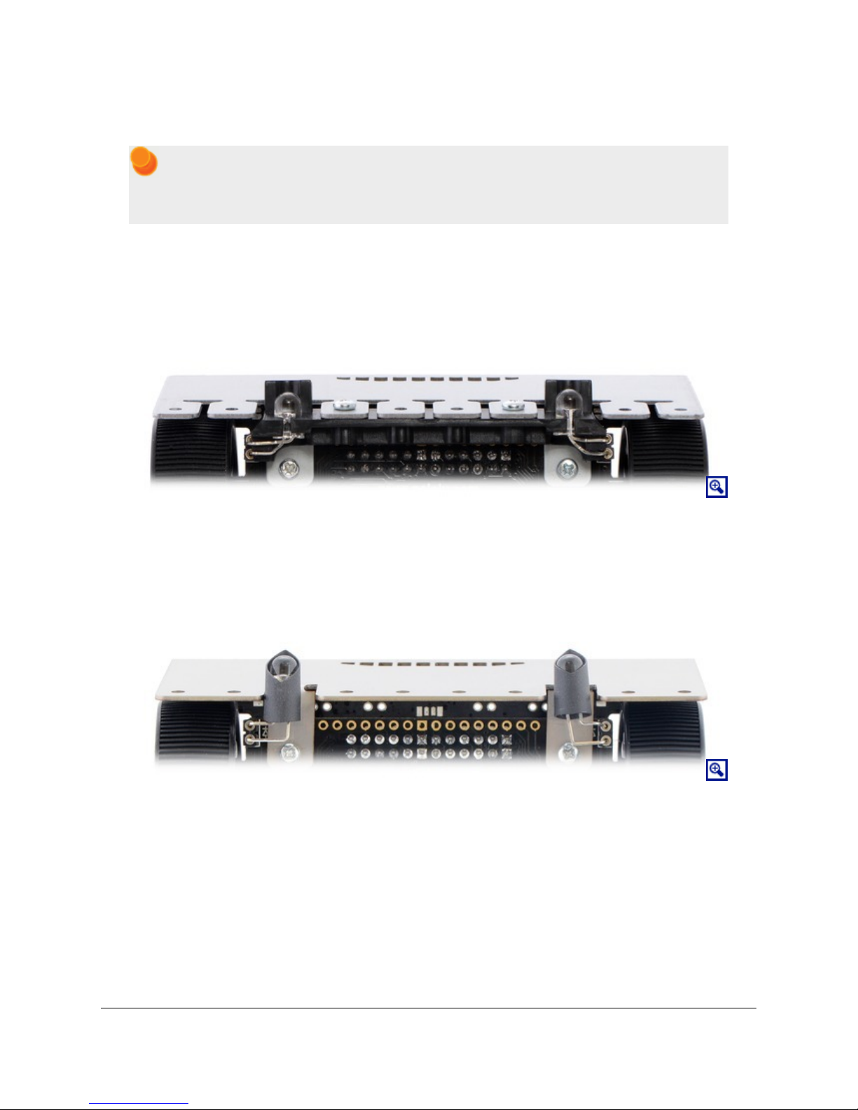
IR LED holder
Note: Kits shipped before August 2015 do not include the LED holder and its mounting screws.
Instead, the forward IR emitter LEDs can be shielded with shrouds made from the included heat
shrink tubing as described below.
Proper shielding for the forward emitters is important; without shielding, light from the LEDs can activate the
proximity sensors directly and cause false readings. The Zumo 32U4 comes with a plastic LED holder that serves
to shield the LEDs while also holding them in place and helping to protect them from collisions with other
robots. The LED holder screws to the blade with the two included 3/16″ #2-28 thread-forming screws. See the
assembly instructions in Section 4 to learn how to properly install the forward emitters with the LED holder.
IR LEDs with LED holder.
Shielding with heat shrink tubing
You can make shrouds out of black heat shrink tubing to shield the forward emitters as an alternative to using the
LED holder. Without the LED holder, the LEDs are less securely mounted, but you can more easily adjust their
positioning.
IR LEDs with heat shrink shielding.
You can test to see if your shielding is good by putting your Zumo on a black surface with no objects nearby and
making sure that you get a reading of 0 for all the proximity sensors.
3/16″ diameter heat shrink tubing can work well (tubing of this size was included with kits prior to August
2015), but please note that the actual diameter of heat shrink tubing often differs significantly from its nominal
diameter, depending on the type and manufacturer of the tubing.
3. The Zumo 32U4 in detail Page 20 of 76

Pololu Zumo 32U4 Robot User’s Guide © 2001–2015 Pololu Corporation
Proximity sensor performance
The proximity sensors have no particular minimum sensing distance; they can sense an object that is close to the
Zumo as long as the shape of that object allows some light from the LEDs to be reflected into the sensor.
The maximum sensing distance depends on the size and reflectivity of the object you are sensing. We did several
tests of the front proximity sensors to see how well they could see the steel blade of another Zumo while both
robots were on the black surface of a sumo ring. In these tests, we found that the maximum sensing distance was
around 30 cm to 40 cm.
There is a significant dead spot between the sensing regions of the front sensor and each side sensor. Therefore,
if the Zumo senses an object with the left or right sensors and then turns to face it, there will probably be a period
of time where none of the sensors can see the object.
Facing towards an object
The FaceTowardsOpponent demo found in the Zumo 32U4 Arduino library (Section 6) uses the motors and the
front proximity sensor to scan for nearby objects, face directly towards them, and track them if they move. To
directly face an object, it compares the two readings from the front sensor: the number of brightness levels for
the left LEDs that resulted in the sensor activating, and the number of brightness levels for the right LEDs that
resulted in the sensor activating. If the left reading is greater than the right reading, it means the object is closer
to the left LEDs, so the robot should turn left (counter-clockwise) to face it more directly. Similarly, if the right
reading is greater than the left reading, the robot should turn right (clockwise). If both of the readings are below
a certain threshold, then it just turns the motors in order to scan for nearby objects.
This could be a good starting point for a sumo robot that uses the front sensors to locate its opponent.
3.7. Inertial sensors
The Zumo 32U4 includes on-board inertial sensors that can be used in advanced applications, such as helping
your Zumo detect collisions and determine its own orientation by implementing an inertial measurement
unit (IMU). The first chip, an ST LSM303D [https://www.pololu.com/product/2127] compass module, combines a
3-axis accelerometer and 3-axis magnetometer into a single package. The second chip is an ST L3GD20H
[https://www.pololu.com/product/2129] 3-axis gyroscope. Both sensor chips share an I²C bus connected to the
ATmega32U4’s I²C interface.
Level shifters built into the main board allow the inertial sensors, which operate at 3.3 V, to be connected to the
ATmega32U4 (operating at 5 V). The sensors, level shifters, and I²C pull-up resistors are connected to the SDA
(digital pin 2, or PD1) and SCL (digital pin 3, or PD0) pins on the AVR by default, but they can be disconnected
by cutting the surface-mount jumpers labeled “2 = SDA” and “3 = SCL” on the board to allow those pins to be
used for other purposes.
We recommend carefully reading the LSM303D datasheet [https://www.pololu.com/file/download/
LSM303D.pdf?file_id=0J703] (1MB pdf) and L3GD20H datasheet [https://www.pololu.com/file/download/
L3GD20H.pdf?file_id=0J731] (3MB pdf) to understand how these sensors work and how to use them.
Using the sensors
The Zumo32U4 library [https://www.pololu.com/docs/0J63/6] includes functions that make it easier to work with
the sensors, as well as some example programs that demonstrate how to use them. (The software interface is
identical to those of our LSM303 Arduino library [https://github.com/pololu/lsm303-arduino] and L3G Arduino
library [https://github.com/pololu/l3g-arduino].)
3. The Zumo 32U4 in detail Page 21 of 76

Pololu Zumo 32U4 Robot User’s Guide © 2001–2015 Pololu Corporation
In addition, the sensor ICs on the Zumo 32U4 are the same as those on our MinIMU-9 v3
[https://www.pololu.com/product/2468], so Arduino software written for the MinIMU-9 (such as our AHRS example
[https://github.com/pololu/minimu-9-ahrs-arduino]) can also be adapted to work on a Zumo 32U4 robot.
Notes on the magnetometer
Please note that the magnetometer in the LSM303 is affected by currents in the motors and buzzer when they
are operating, as well as metal in the batteries, and the readings are easily influenced by magnetic distortions in
the environment around the Zumo (such as rebar in a concrete floor). As a result, it is very hard to accurately
determine the Zumo’s absolute heading based on the magnetometer data. However, in our tests, we found that the
magnetometer could still be useful for rough measurements of relative orientation changes; for example, once
the magnetic readings are compensated for a particular environment, they can be used to help the Zumo turn left
or right by a specific angle instead of just timing how long to run the motors to make such a turn (although the
gyro or encoders might be better suited for this particular purpose).
In our tests, we found that the batteries, motors, and motor current affect the z axis of the
magnetometer much more strongly than the x and y axes, so you probably will want to ignore
the z readings. We were generally able to get decent results using only the x and y magnetometer
readings to determine heading. Additionally, you might need to decrease the magnetometer
sensitivity; if the magnetometer returns a value of -4096, that is a sign that the sensitivity range is
set too narrow for your particular environment.
3.8. Power
The Zumo chassis has an internal compartment for four AA batteries. We recommend using rechargeable AA
NiMH cells [https://www.pololu.com/product/1003], which results in a nominal voltage of 4.8 V (1.2 V per cell). You
can also use alkaline cells, which would nominally give you 6 V.
The negative battery voltage is connected to GND. The positive battery voltage is designated VB. VB feeds into
a circuit that provides reverse protection and power switching controlled by the on-board power switch. The
output of this circuit is designated VBAT.
VBAT provides power to the motors through the DRV8838 motor drivers, so the motors can only operate if the
batteries are installed and the power switch is in the “On” position.
The battery voltage on VBAT can be monitored through a voltage divider that is connected to analog pin 1
(PF6) by default. The divider outputs a voltage that is equal to one half of the battery voltage, which will be
safely below the ATmega32U4’s maximum analog input voltage of 5 V as long as the battery voltage is less than
10 V. The readBatteryMillivolts() function in the Zumo32U4 library [https://www.pololu.com/docs/0J63/6] can
be used to determine the battery voltage from this reading. The surface-mount jumper labeled “A1 = VBAT/2”
can be cut to disconnect the voltage divider and free the pin for other uses.
5V regulator
VBAT supplies power to a 5V regulator based on the TPS63061 switching step-up/step-down (buck-boost)
converter from Texas Instruments. The regulator works with a 2.7 V to 11.8 V input voltage (although the
motor drivers limit the maximum operating voltage of the Zumo 32U4 to 11 V) and has a typical efficiency
of 80% to 90% for most combinations of input voltage and load. (We also make a standalone regulator
[https://www.pololu.com/product/2119] based on this integrated circuit.) The 5V output of this regulator is designated
VREG.
3. The Zumo 32U4 in detail Page 22 of 76

Pololu Zumo 32U4 Robot User’s Guide © 2001–2015 Pololu Corporation
The regulator can be disabled by driving the regulator shutdown pin, SHDN, high.
Power selection
The Zumo 32U4 main board’s power selection circuit uses the TPS2113A power multiplexer
[https://www.pololu.com/product/2596] from Texas Instruments to choose whether its 5 V logic supply (designated
5V) is sourced from USB or the batteries via the regulator, enabling the robot to safely and seamlessly transition
between the two sources. The TPS2113A is configured to select regulated battery power (VREG) unless the
regulator output falls below about 4.5 V. If this happens, it will select the higher of the two sources, which will
typically be the USB 5 V bus voltage if the Zumo is connected to USB.
Consequently, when the Zumo 32U4 is connected to a computer via USB, it will receive 5 V logic power even
when the power switch is off. This can be useful if you want to upload or test a program without drawing power
from the batteries and without operating the motors. It is safe to have USB connected and battery power switched
on at the same time.
The currently selected source is indicated by the STAT pin; this pin is an open-drain output that is low
if the batteries are selected and high-impedance if the USB supply is selected. The current limit of the
TPS2113A is set to about 1.9 A. For more information about the power multiplexer, see the TPS2113A
datasheet [https://www.pololu.com/file/download/tps2113a.pdf?file_id=0J771] (1MB pdf).
3.3V regulator
The main board also has 3.3 V linear regulator. The inertial sensors draw power from the 3.3 V line; the
remainder (up to a few hundred milliamps) is available for powering external circuits or devices.
Alternative power sources
For users who want to experiment with alternative power sources like lithium batteries, the Zumo 32U4 can
accept a battery input voltage from 2.7 V to 10 V. You can raise the maximum allowable voltage to the motor
drivers’ limit of 11 V by disconnecting or modifying the battery voltage divider.
We do not recommend using a 3-cell lithium battery to power the Zumo 32U4. Even though such
a battery is usually specified with a nominal voltage of 11.1 V, it can measure well over 12 V
when fully charged.
Adding a power switch
You can add your own power switch to the Zumo 32U4 using the PSW pin. When it is in the on position, your
switch should connect PSW to GND. In that case, VBAT will receive power when either your switch or the main
board switch are on.
3.9. Expansion areas
The top expansion areas on the Zumo 32U4 main board (in two 2×13 groups of pins near the left and right edges)
break out all of the ATmega32U4 microcontroller’s general-purpose I/O lines and provide access to various
power inputs and outputs. Some of these pins are also broken out in the front expansion area, where the front
sensor array connects. The following diagrams identify the locations of these pins and the hardware associated
with them.
3. The Zumo 32U4 in detail Page 23 of 76
 Loading...