

Pololu Corporation Orangutan SVP User Manual
Pololu Orangutan SVP User's Guide © 2001–2010 Pololu Corporation
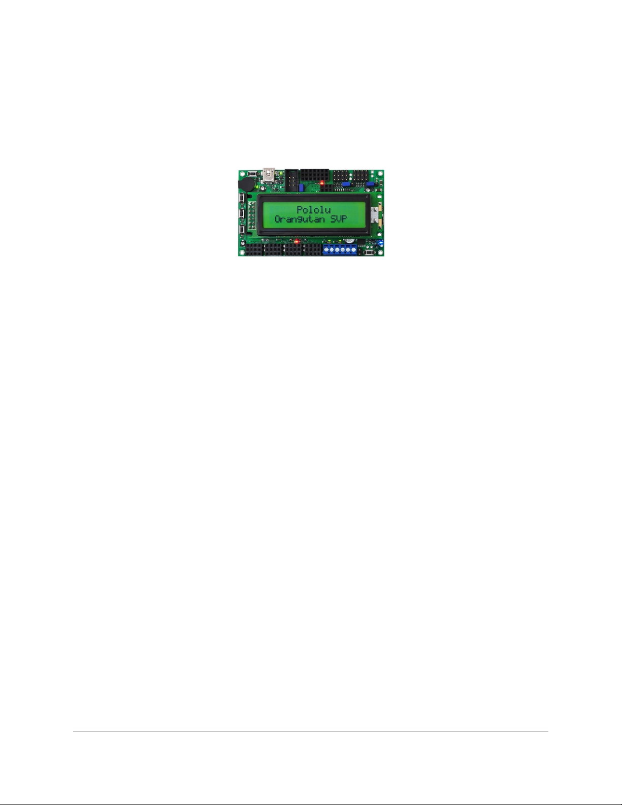
Pololu Orangutan SVP
User's Guide
1. Overview . . . . . . . . . . . . . . . . . . . . . . . . . . . . . . . . . . . . . . . . . 2
1.a. Supported Operating Systems . . . . . . . . . . . . . . . . . . . . . . . . . . . 3
2. Contacting Pololu . . . . . . . . . . . . . . . . . . . . . . . . . . . . . . . . . . . . . 5
3. Schematic Diagrams . . . . . . . . . . . . . . . . . . . . . . . . . . . . . . . . . . . 6
4. Module Pinout and Components . . . . . . . . . . . . . . . . . . . . . . . . . . . . . 7
5. Getting Started . . . . . . . . . . . . . . . . . . . . . . . . . . . . . . . . . . . . . 13
5.a. Installing Windows Drivers . . . . . . . . . . . . . . . . . . . . . . . . . . . . 13
5.b. Using the Demo Program . . . . . . . . . . . . . . . . . . . . . . . . . . . . . 16
5.c. Programming Your Orangutan . . . . . . . . . . . . . . . . . . . . . . . . . . 17
5.d. Assembling the kit version . . . . . . . . . . . . . . . . . . . . . . . . . . . . 19
6. AVR Pin Assignment Table Sorted by Function . . . . . . . . . . . . . . . . . . . . . 23
7. AVR Pin Assignment Table Sorted by Pin . . . . . . . . . . . . . . . . . . . . . . . . 24
8. Using the USB Communication Port . . . . . . . . . . . . . . . . . . . . . . . . . . 27
9. Using the TTL Serial Port . . . . . . . . . . . . . . . . . . . . . . . . . . . . . . . . 30
10. Motor Driver Truth Table . . . . . . . . . . . . . . . . . . . . . . . . . . . . . . . 32
11. USB Power . . . . . . . . . . . . . . . . . . . . . . . . . . . . . . . . . . . . . . 33
12. Upgrading Firmware . . . . . . . . . . . . . . . . . . . . . . . . . . . . . . . . . 34
13. Related Resources . . . . . . . . . . . . . . . . . . . . . . . . . . . . . . . . . . . 37
Page 1 of 37

Pololu Orangutan SVP User's Guide © 2001–2010 Pololu Corporation
1. Overview
The Orangutan SVP robot
controller [http://www.pololu.com/catalog/product/1325] is a
complete control solution for small and medium-sized robots
running at 6 – 13.5 V. The module is designed around the
powerful Atmel ATmega324PA AVR microcontroller (32 KB
ash, 2 KB RAM, and 1 KB EEPROM) or ATmega1284P
(128 KB ash, 16 KB RAM, and 4 KB EEPROM) running at
20 MHz and features a full complement of peripheral
hardware to support robotics applications: dual motor drivers capable of delivering 2 A
continuous (6 peak) per channel, a demultiplexer for easy control of up to eight servos with a
single hardware PWM, a removable 16×2 character LCD with backlight, a user trimmer
potentiometer, a buzzer for simple sounds and music, three user pushbuttons, and two user
LEDs. The board also provides 21 free I/O lines, of which 12 can be used as analog inputs,
and two switching buck (step-down) voltage regulators—one for the 5V bus and one
adjustable from 2.5 V to 85% of VIN—each capable of supplying 3 A, which means there’s
plenty of room and power for adding sensors, servos, and other peripherals.
In addition to the user-programmable AVR microcontroller, the Orangutan SVP features an
auxiliary PIC18F14K50 MCU that supports the main processor and serves as an integrated
AVR ISP programmer, which means that no external programmer is required to use the
Orangutan SVP. This auxiliary processor provides a USB connection that allows direct
communication with a PC, and its rmware lets it perform several useful task in parallel
with the main microcontroller. For example, the auxiliary processor can read two quadrature
encoders without burdening the main MCU, or those same four inputs could be used as
additional analog inputs. The ATmega324 or ATmega1284 can read data from the auxiliary
MCU over SPI. A USB A to mini-B cable [http://www.pololu.com/catalog/product/130] is
included with the Orangutan SVP.
Because the Orangutan SVP gives the user direct access to the AVR microcontroller, it
is compatible with all development software for Atmel’s AVR microcontrollers, including
Atmel’s free AVR Studio [http://www.atmel.com/avrstudio/] and the
WinAVR [http://winavr.sourceforge.net/] GCC C/C++ compiler. We provide an extensive set of
software libraries [http://www.pololu.com/docs/0J20] that make it easy to interface with all
of the integrated hardware, including the auxiliary microcontroller. Using these libraries,
it takes just a few simple lines of code to write to the LCD, read button presses, drive
motors, and control servos. These libraries come with a number of sample programs that
demonstrate how to use the various components on the Orangutan SVP.
Specications & On-Board Hardware
• Overall unit dimensions: 3.70" × 2.20"
• Input voltage: 6 – 13.5 V
• Programmable 20 MHz Atmel ATmega324PA AVR microcontroller with 32 KB ash,
2 KB SRAM, and 1 KB EEPROM *
• Programmable 20 MHz Atmel ATmega1284P AVR microcontroller with 128 KB ash,
16 KB RAM, and 4 KB EEPROM *(SVP-1284 version)
• Built-in USB AVR ISP programmer (USB A to mini-B
cable [http://www.pololu.com/catalog/product/130] included)
• 2 bidirectional motor ports (2 A continuous per channel, 6 A maximum per channel)
1. Overview Page 2 of 37
Pololu Orangutan SVP User's Guide © 2001–2010 Pololu Corporation
• 8-output demultiplexer tied to one of the AVR’s hardware PWMs for easy control of
up to 8 servos
• 21 free I/O lines
◦ 17 free I/O lines on the main MCU, of which 8 can be analog inputs
◦ 4 input lines on the auxiliary processor, which can be either 4 analog inputs or
dual quadrature encoder inputs
◦ 2 hardware UARTs
• Removable 16-character × 2-line LCD with backlight
• Primary 5V switching regulator capable of supplying 3 A
• Secondary adjustable (2.5 V – 85% of VIN) buck (step-down) voltage regulator
capable of supplying 3 A
• Buzzer tied to one of the AVR’s hardware PWMs
• 3 user pushbutton switches
• 2 user LEDs
• Power (push-on/push-o) and reset pushbutton switches
• Power circuit makes it easy to add extra power buttons and provides a self-shutdown
option
• Auxiliary processor (connected via SPI) provides:
◦ Battery voltage reading
◦ User trimmer potentiometer reading
◦ Integrated USB connection
◦ In-System-Programming of the main processor
◦ Ability to read two quadrature encoders
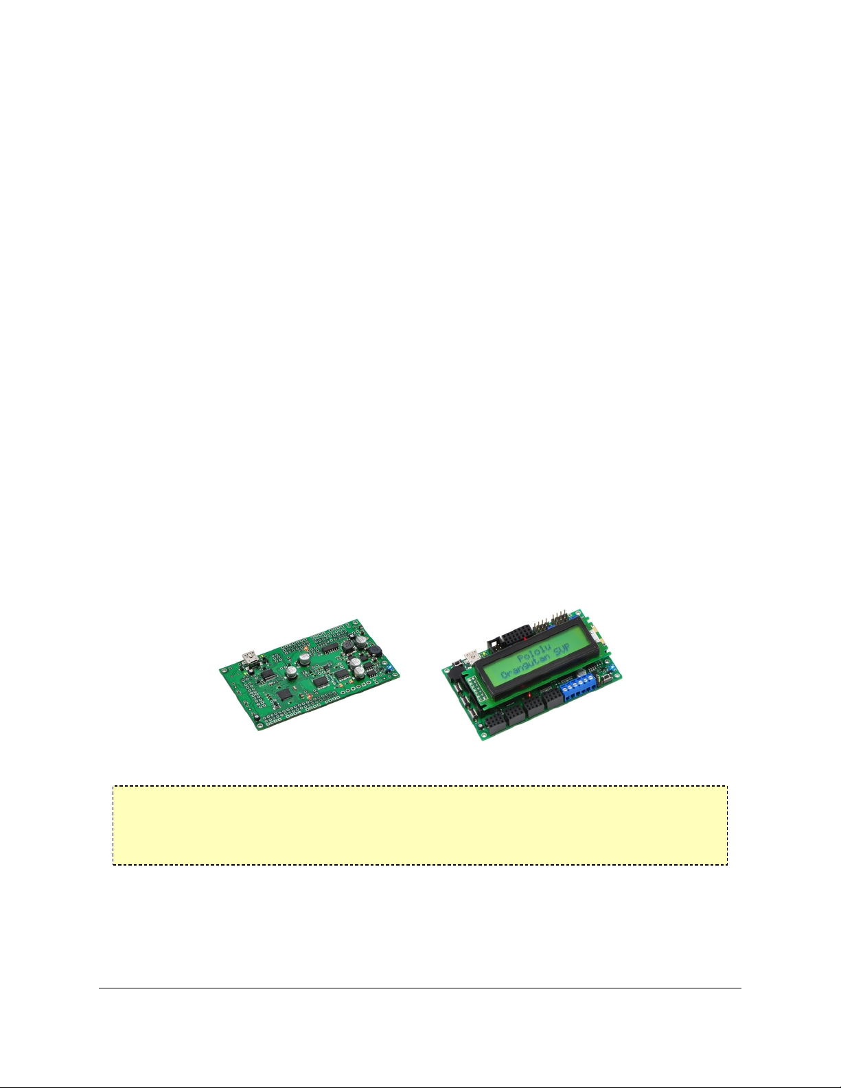
Orangutan SVP kit.
Orangutan SVP fully assembled.
For a Spanish version of this document, please see Orangutan SVP Guia de
Usuario [http://www.pololu.com/le/download/OrangutanSVPGuiaUsuario.pdf?le_id=0J328]
(1725k pdf) (provided by customer Jaume B.).
1.a. Supported Operating Systems
The Orangutan SVP’s USB connection works under Microsoft Windows XP, Windows Vista,
Windows 7, and Linux. The Orangutan SVP’s USB connection can be used to program the
1. Overview Page 3 of 37

Pololu Orangutan SVP User's Guide © 2001–2010 Pololu Corporation
AVR, communicate directly with the AVR from a computer, or communicate with TTL-level
serial devices from a computer.
Under Linux, the three virtual COM ports created by the SVP should appear as devices with
names like /dev/ttyACM0, /dev/ttyACM1, and /dev/ttyACM2 (the numbers depends on how
many other ACM devices you have plugged in) and you can use any terminal program (such
as kermit) to send and receive bytes on those ports.
The Orangutan SVP’s USB connection is not compatible with any version of Mac OS.
Note: You may not need to use the Orangutan SVP’s USB connection. If you have
an AVR ISP programmer, then you can program the AVR on the Orangutan SVP
by connecting your programmer to the 6-pin AVR ISP header located near the
SVP’s USB connector. In that case, the operating system of your computer does not
matter, as long as your programmer works.
1. Overview Page 4 of 37

Pololu Orangutan SVP User's Guide © 2001–2010 Pololu Corporation
2. Contacting Pololu
You can check the Orangutan SVP-324 robot controller
page [http://www.pololu.com/catalog/product/1325] or Orangutan SVP-1284 robot controller
page [http://www.pololu.com/catalog/product/1327] for additional information, including
pictures, example code, and application notes. You can also nd libraries for interacting
with the on-board hardware and an assortment of sample code in the Pololu AVR
Library [http://www.pololu.com/docs/0J20].
We would be delighted to hear from you about any of your projects and about your
experience with the Orangutan Robot controllers. You can contact
us [http://www.pololu.com/contact] directly or post on our forum [http://forum.pololu.com/]. Tell
us what we did well, what we could improve, what you would like to see in the future, or
anything else you would like to say!
2. Contacting Pololu Page 5 of 37

Pololu Orangutan SVP User's Guide © 2001–2010 Pololu Corporation
3. Schematic Diagrams
Schematic diagrams of the Orangutan SVP are available here: Orangutan SVP schematic
diagram [http://www.pololu.com/le/download/org06a02_schematic.pdf?le_id=0J265] (99k pdf)
3. Schematic Diagrams Page 6 of 37
Pololu Orangutan SVP User's Guide © 2001–2010 Pololu Corporation
4. Module Pinout and Components
sThe Orangutan SVP contains a programmable AVR ATmega324PA or ATmega1284P
microcontroller connected to two motor drivers for direct control of two DC motors, a 16×2
character LCD, a buzzer, three user pushbuttons, two user LEDs, and a demultiplexer for
servo control. The AVR is also connected to an auxiliary processor (a PIC18F14K50) that
provides access to the battery voltage, a 10 kilo-ohm user trimmer potentiometer, and four
additional input lines. The auxiliary processor also serves as a programmer for the main
processor, meaning that an external programmer is not required, but you can use one if you
want to. The auxiliary processor also allows for USB communication between the AVR and a
personal computer, and acts as a USB-to-serial converter.
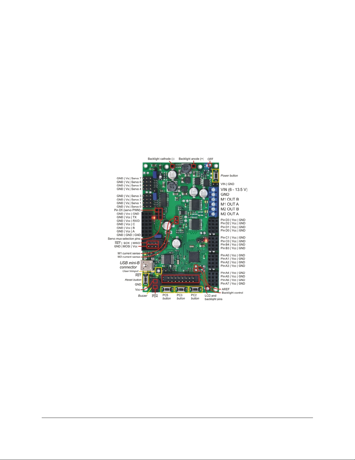
These and the rest of the main features of the module are labeled in the pictures above. Most
of the connection points are also indicated on the silkscreen on the back side of the PCB, as
shown below. The overall unit dimensions are 3.7” × 2.2”, and four 0.086” mounting holes,
suitable for #2 screws, are located 0.1” from the corners of the board.
Orangutan SVP fully assembled PCB with pins labeled.
Power & Motor Connections
The power and motor connections are in the lower-right corner of the unit. The Orangutan
SVP’s input voltage (VBAT) should be 6 – 13.5 V, from which the on-board regulator
generates the 5 V supply (VCC) that is used to power the logic.
The Orangutan SVP has one TB6612FNG motor driver for each motor output. Each motor
driver can deliver a continuous 2 A, and can briey deliver up to 6 A. If you are not
taking extra steps to keep the motor driver cool, such as using a heat sink, exceeding this
continuous current rating for too long will cause the motor driver to heat up and trigger its
built-in thermal shutdown.
By default, the motor drivers are powered from the external power supply (VBAT). However,
you can disconnect the external power supply from the motor drivers by cutting the labeled
4. Module Pinout and Components Page 7 of 37

Pololu Orangutan SVP User's Guide © 2001–2010 Pololu Corporation
traces on the bottom of the board (VBAT-VM1 and VBAT-VM2). This allows you to connect
some other power supply to the motor drivers, such as VADJ (see below). The motor drivers
have an operating range of 4.5 – 13.5 V, so your power supply should be in that range, and
should be capable of supplying all the current that your motors might draw.
USB Power
When connected to a computer, the USB connection provides a 5 V power supply. If an
external power supply is present, the unit will run o of the external supply and not draw any
power from USB. If only the USB power is present, then by default the auxiliary processor
will be powered from USB, but the AVR and the VCC power pins on the board will not be
powered. An option is available for powering the entire board from USB. See Section 11 for
more information.
Motors
The motor drivers are controlled by two of the AVR’s hardware PWM outputs from eightbit Timer2 for speed control, along with two digital outputs for direction control. This lets
you achieve variable motor speeds using hardware PWMs rather than processor-intensive
software PWMs on the motor control lines. You can control the motors using the functions
in the OrangutanMotors [http://www.pololu.com/docs/0J18/7] section of the Pololu AVR C/C++
Library.
For each motor, the Orangutan SVP has a current-sensing circuit that produces an output
voltage proportional to the current the motors are using (850 mV/A). The respective outputs
of these circuits are labeled CS1 and CS2, and they are accessible near the center of the
board.
User I/O & Power Outputs
Sixteen user I/O lines can be accessed via the four 4×3 0.100” female headers along the
lower edger of the board, as shown below. Each I/O line has associated power and ground
connections for easy connections to sensors: the exterior (bottom) pin is ground, the middle
pin is power, and the interior (top) pin is signal and connects directly to an AVR I/O line.
For each four-pin bank of I/O lines, you can congure which power voltage is supplied to the
power (middle) pins. By default, the power pins are connected to VCC (5 V). You can cut a
trace on the bottom of the board to disconnect them from VCC. This will leave the power
pins connected to one through-hole, which can be connected to a dierent power source,
such as VBAT, which is available elsewhere on the board.
The total current available on the VCC (5 V) line is 3 A, meaning you can power servos and
other high-power peripherals directly from your regulated voltage.
LCD
The Orangutan SVP is supplied with a removable 16×2 character LCD with backlight
that uses the common HD44780 parallel interface [http://www.pololu.com/le/download/
DMC50448N-AAE-AD.pdf?le_id=0J71] (109k pdf). A dierent LCD can be connected with an
appropriate cable. The AVR has four I/O lines connected to LCD data lines DB4 – DB7 (i.e.
is congured to use the LCD in 4-bit mode) and three I/O lines connected to the three LCD
control lines RS, R/W, and E. Please note that the LCD data lines are also shared by the user
pushbuttons and the green user LED. You can print to the LCD using the functions in the
OrangutanLCD [http://www.pololu.com/docs/0J18/5] section of the Pololu AVR C/C++ Library.
4. Module Pinout and Components Page 8 of 37

Pololu Orangutan SVP User's Guide © 2001–2010 Pololu Corporation
The LCD’s backlight can be turned o by driving the BACKLIGHT line low. Adjustable
dimming of the LCD can be achieved by connecting the line to a free PWM output.
The AVR’s AREF pin is available next to the backlight pin.
Pushbuttons
The Orangutan SVP has ve total pushbuttons: a power on/o button located on the right
side of the bottom edge of the board, a reset button located on the left side of the top edge
of the board, and three user pushbuttons located along the left edge of the board. Please
note that the power button disconnects the external power supply from the entire board,
while the reset button connects directly to the AVR’s RESET pin and does not disconnect the
power supply.
The user pushbuttons, from top to bottom, are on pins PC5, PC3, and PC2. Pressing one
of these buttons pulls the associated I/O pin to ground through a resistor. You can detect
button pushes using the functions in the OrangutanPushbuttons [http://www.pololu.com/docs/
0J18/8] section of the Pololu AVR C/C++ Library. The library takes care of conguring the
pins as inputs, enabling the AVR’s internal pull-up resistors, and debouncing (accounting for
the fact that pushbuttons physically bounce when pressed).
Buzzer
The Orangutan SVP comes with a buzzer controlled by pin PD4. If you alternate between
driving the buzzer pin high and low at a given frequency, the buzzer will produce sound
at that frequency. You can use the functions in the
OrangutanBuzzer [http://www.pololu.com/docs/0J18/3] section of the Pololu AVR C/C++
Library to play notes in the background (using hardware PWM) while the rest of your
processor performs other tasks.
Trimpot
The Orangutan SVP comes with a 10 kilo-ohm user trimmer potentiometer, located between
the USB connector and the LCD connector. The trimpot is connected to the auxiliary
processor, which measures its output voltage and reports it to the AVR.
You can disconnect the trimpot from the auxiliary processor by cutting the labeled trace
between POT and ADC/SS on the bottom side of the board. This gives you two options for
that line: you can use it as a general-purpose analog input by connecting some other output
to it, or you can connect it to one of your AVR’s free I/O lines and use it as the SPI slaveselect line for the auxiliary processor, allowing you to communicate with some other SPI
peripheral.
Programming Connector
The Orangutan SVP has a 6-pin programming connector on the upper left side. This gives
you the option of using an AVR ISP in-system programmer from Atmel or a compatible
programmer, such as our Pololu USB AVR Programmer [http://www.pololu.com/catalog/
product/1300] to program the AVR. This is not necessary, though, because the Orangutan
SVP’s auxiliary processor can serve as an AVR ISP programmer for the AVR.
By default, pin 5 of the Programming connector, which is labeled by an asterisk (*), is
connected to the AVR’s RESET line, which is necessary for ISP programming by an external
device). However, you can disconnect those two pins by cutting a labeled trace on the
bottom of the circuit board. This gives you the option of using that line for some other signal.
4. Module Pinout and Components Page 9 of 37
Pololu Orangutan SVP User's Guide © 2001–2010 Pololu Corporation
Auxiliary I/O & Power Outputs
The Orangutan SVP has ve auxiliary I/O lines that are connected to the auxiliary processor.
Each I/O line has associated power and ground connections for easy connections to sensors:
the exterior (top) pin is ground, the middle pin is power (VCC), and the interior (bottom)
pin is signal and connects directly to an auxiliary processor I/O line. The TX line is the
serial transmit line. It transmits TTL-level serial bytes received from the computer on the
“Pololu Orangutan SVP TTL Serial Port”. The lines A, B, C, and D/RX can be congured
to do dierent things. They can function as three analog inputs plus a serial receive
line, as four analog inputs, or as the inputs for two quadrature encoders. See the
OrangutanSVP [http://www.pololu.com/docs/0J18/12] section of the Pololu AVR C/C++ Library
for more information.
Servo Demultiplexer
The hardware in the upper-right corner of the Orangutan SVP allows you to control up
to 8 servos without sacricing a large number of I/O lines or processor cycles. You can
control servos using the functions in the OrangutanServos [http://www.pololu.com/docs/0J18/
10] section of the Pololu USB AVR C/C++ library.
The input signal of the demultiplexer is connected to pin PD5 on the AVR. If you are not
using PD5 to control servos, you can use it as a general-purpose digital I/O line or PWM
output.
The three output-selection pins of the multiplexer (SA, SB, and SC) are available in the
header near the multiplexer so they can be wired to free I/O lines on the AVR, allowing you
to switch between servos. The output-selection pins have pull-down resistors, so if you have
four servos or fewer you can leave some of them disconnected.
The eight output pins of the multiplexer are available in two 4×3 headers. These lines have
current-limiting resistors on them. Each multiplexer output line has associated power and
ground connections for easy connections to the servos: the exterior (top) pin is ground, the
middle pin is power. For each bank of servos, you can congure which power supply is
connected to the power pins, using the provided headers and jumpers. You can power the
servos from VCC, VADJ (see below), or a separate power supply.
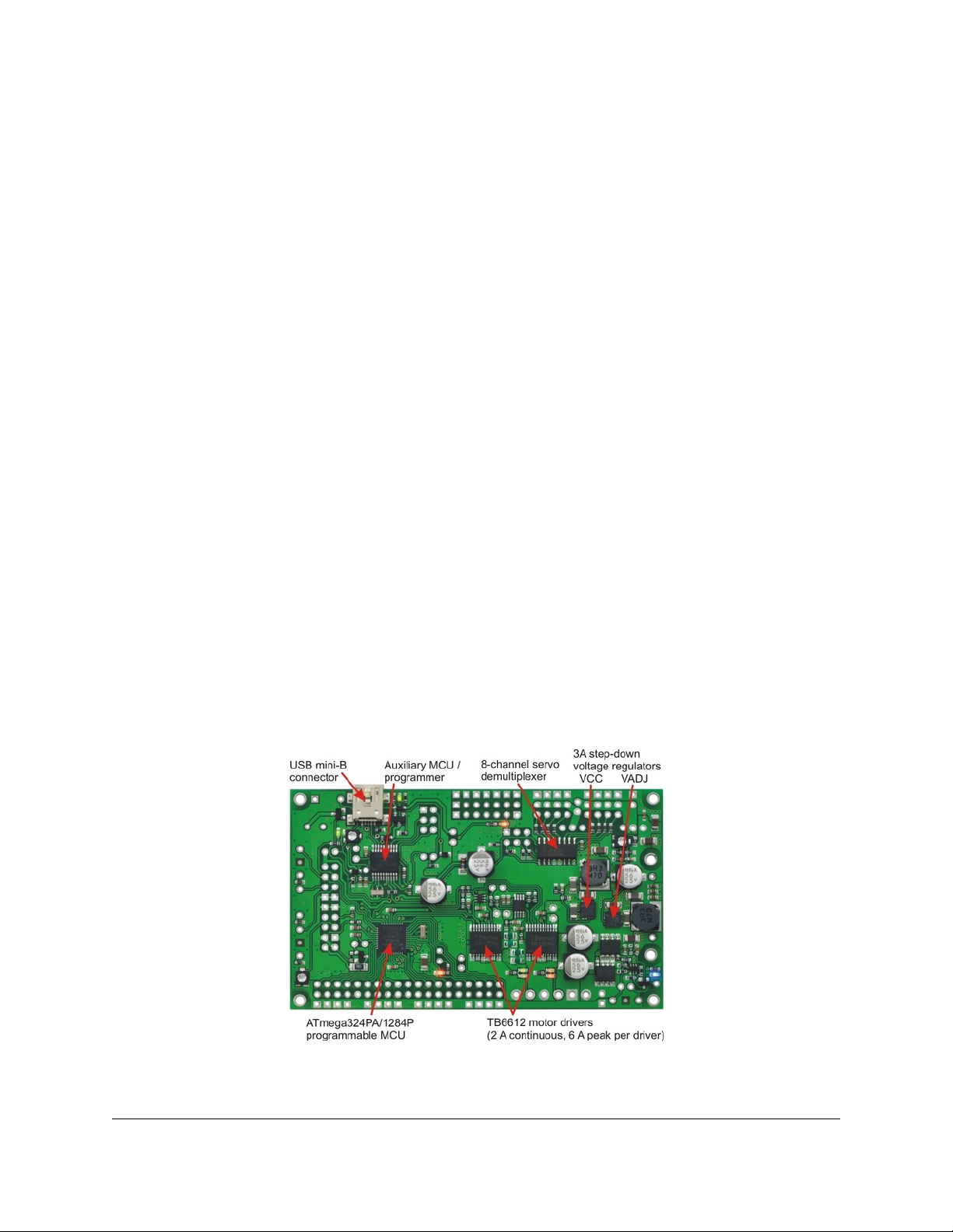
Orangutan SVP with key integrated hardware labeled.
4. Module Pinout and Components Page 10 of 37
Pololu Orangutan SVP User's Guide © 2001–2010 Pololu Corporation
Adjustable Voltage (VADJ)
In addition to the 5 V regulator that supplies VCC, the Orangutan SVP comes with an
adjustable voltage regulator. Both regulators can supply a current of 3 A. The adjustable
voltage regulator draws current from the external power supply (VBAT), and produces an
output voltage called VADJ. The trimmer potentiometer in the upper right corner of the
board determines VADJ. If you turn the trimpot all the way counter-clockwise, VADJ goes
down to about 2.5 V. If you turn it all the way clockwise, VADJ rises to 85% of VIN.
In general, it is advantageous to power servos and other high-power devices from VADJ
(instead of VCC), because if the peripherals draw too much current for the power supply to
handle the AVR will not be aected.
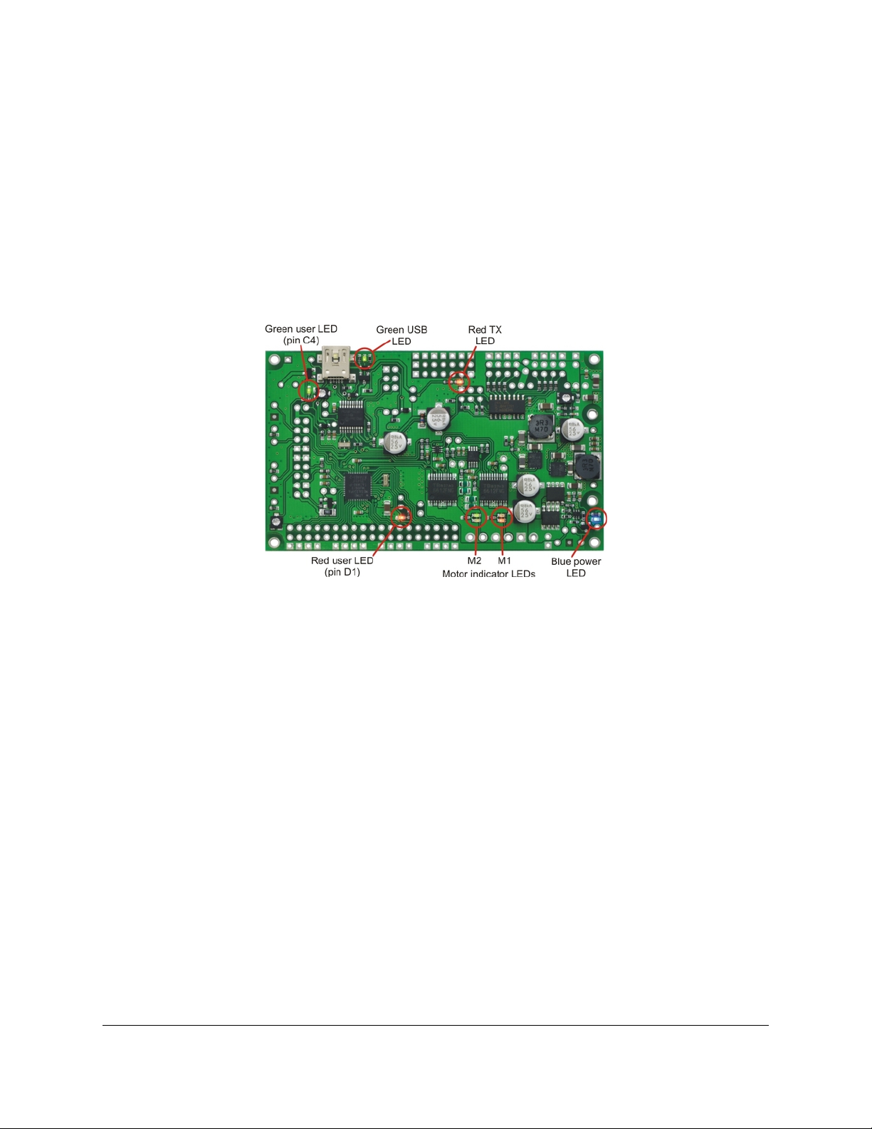
LEDs
Orangutan SVP LEDs.
The Orangutan SVP comes with 9 LEDs:
• A blue power LED is located next to the power button.
• There are four motor indicator LEDs located near the motor outputs. A green LED lit
indicates that the corresponding motor is being driven “forward” (the voltage on output
B is higher than the voltage on A). A red LED indicates that the corresponding motor is
being driven in “reverse” (the voltage on output B is lower than the voltage on output
A).
• A red user LED is located near the AVR I/O banks. The LED is connected to the
user I/O line PD1. It will light if you set PD1 as a low output. Since PD1 is the serial
transmit line for UART0 (TXD0), the LED will icker whenever serial data is being
transmitted from the AVR. The LED can be disconnected from PD1 by cutting a labeled
trace (PD1-LED) on the bottom of the board.
• A green user LED is located between the trimpot and the buzzer. It will light if you
set PC4 as a high output. Note that PC4 is also used as an LCD data line, so you will see
the green LED icker when you update the LCD.
• Another green LED is located near the USB connector. This LED is controlled by the
auxiliary processor and indicates the status of the USB connection. When the USB is
disconnected, or the device is in the USB Suspend state (because the computer went to
sleep), the green LED is o. When you connect the device to a computer via USB, the
green LED will start blinking slowly. The blinking continues until it receives a particular
message from the computer indicating that the drivers are installed correctly. After the
4. Module Pinout and Components Page 11 of 37

Pololu Orangutan SVP User's Guide © 2001–2010 Pololu Corporation
programmer gets this message, the green LED will be on, but it will icker briey when
there is USB activity.
• Another red LED is located near the header for the auxiliary processor’s TX line.
This LED is tied to the TX line, so it will icker whenever the auxiliary processor is
transmitting TTL-level serial bytes from the computer. This LED will also blink when the
auxiliary processor powers up to indicate bad startup conditions. Two blinks indicates
that a brown-out reset was triggered: the processor’s VDD dropped below 3.0 V. If this
happens to you, check your power connections and battery voltage, and make sure you
are not drawing too much power from the board.
4. Module Pinout and Components Page 12 of 37
 Loading...