

Page 1
Pololu A-Star 32U4 User’s Guide © 2001–2014 Pololu Corporation
Pololu A-Star 32U4 User’s Guide
1. Overview . . . . . . . . . . . . . . . . . . . . . . . . . . . . . . . . . . . . . . . . . . . . . . . . . . . . . . 2
1.1. Supported operating systems . . . . . . . . . . . . . . . . . . . . . . . . . . . . . . . . . . . . . . . . 3
2. Contacting Pololu . . . . . . . . . . . . . . . . . . . . . . . . . . . . . . . . . . . . . . . . . . . . . . . . . . 4
3. A-Star 32U4 Micro . . . . . . . . . . . . . . . . . . . . . . . . . . . . . . . . . . . . . . . . . . . . . . . . . 5
3.1. A-Star 32U4 Micro pinout and components . . . . . . . . . . . . . . . . . . . . . . . . . . . . . . . . 5
3.2. A-Star 32U4 Micro schematic and dimensions . . . . . . . . . . . . . . . . . . . . . . . . . . . . . . . 7
4. A-Star 32U4 Mini . . . . . . . . . . . . . . . . . . . . . . . . . . . . . . . . . . . . . . . . . . . . . . . . . 9
4.1. A-Star 32U4 Mini pinout and components . . . . . . . . . . . . . . . . . . . . . . . . . . . . . . . . . 9
4.2. A-Star 32U4 Mini ULV regulator . . . . . . . . . . . . . . . . . . . . . . . . . . . . . . . . . . . . . . 11
4.3. A-Star 32U4 Mini LV regulator . . . . . . . . . . . . . . . . . . . . . . . . . . . . . . . . . . . . . . . 12
4.4. A-Star 32U4 Mini SV regulator . . . . . . . . . . . . . . . . . . . . . . . . . . . . . . . . . . . . . . . 13
4.5. A-Star 32U4 Mini schematic and dimensions . . . . . . . . . . . . . . . . . . . . . . . . . . . . . . . 13
5. Getting started . . . . . . . . . . . . . . . . . . . . . . . . . . . . . . . . . . . . . . . . . . . . . . . . . . . 15
5.1. Installing Windows drivers . . . . . . . . . . . . . . . . . . . . . . . . . . . . . . . . . . . . . . . . . 15
5.2. Programming using the Arduino IDE . . . . . . . . . . . . . . . . . . . . . . . . . . . . . . . . . . . . 16
5.3. Programming using avr-gcc and AVRDUDE . . . . . . . . . . . . . . . . . . . . . . . . . . . . . . . . 20
6. The A-Star 32U4 USB interface . . . . . . . . . . . . . . . . . . . . . . . . . . . . . . . . . . . . . . . . . . 22
7. The A-Star 32U4 Bootloader . . . . . . . . . . . . . . . . . . . . . . . . . . . . . . . . . . . . . . . . . . . . 24
8. Reviving an unresponsive A-Star . . . . . . . . . . . . . . . . . . . . . . . . . . . . . . . . . . . . . . . . . 27
8.1. Reviving using the Arduino IDE . . . . . . . . . . . . . . . . . . . . . . . . . . . . . . . . . . . . . . 27
8.2. Reviving using AVRDUDE . . . . . . . . . . . . . . . . . . . . . . . . . . . . . . . . . . . . . . . . . 29
9. Related Resources . . . . . . . . . . . . . . . . . . . . . . . . . . . . . . . . . . . . . . . . . . . . . . . . . 30
http://www.pololu.com/docs/0J61/all Page 1 of 30
Page 2
Pololu A-Star 32U4 User’s Guide © 2001–2014 Pololu Corporation
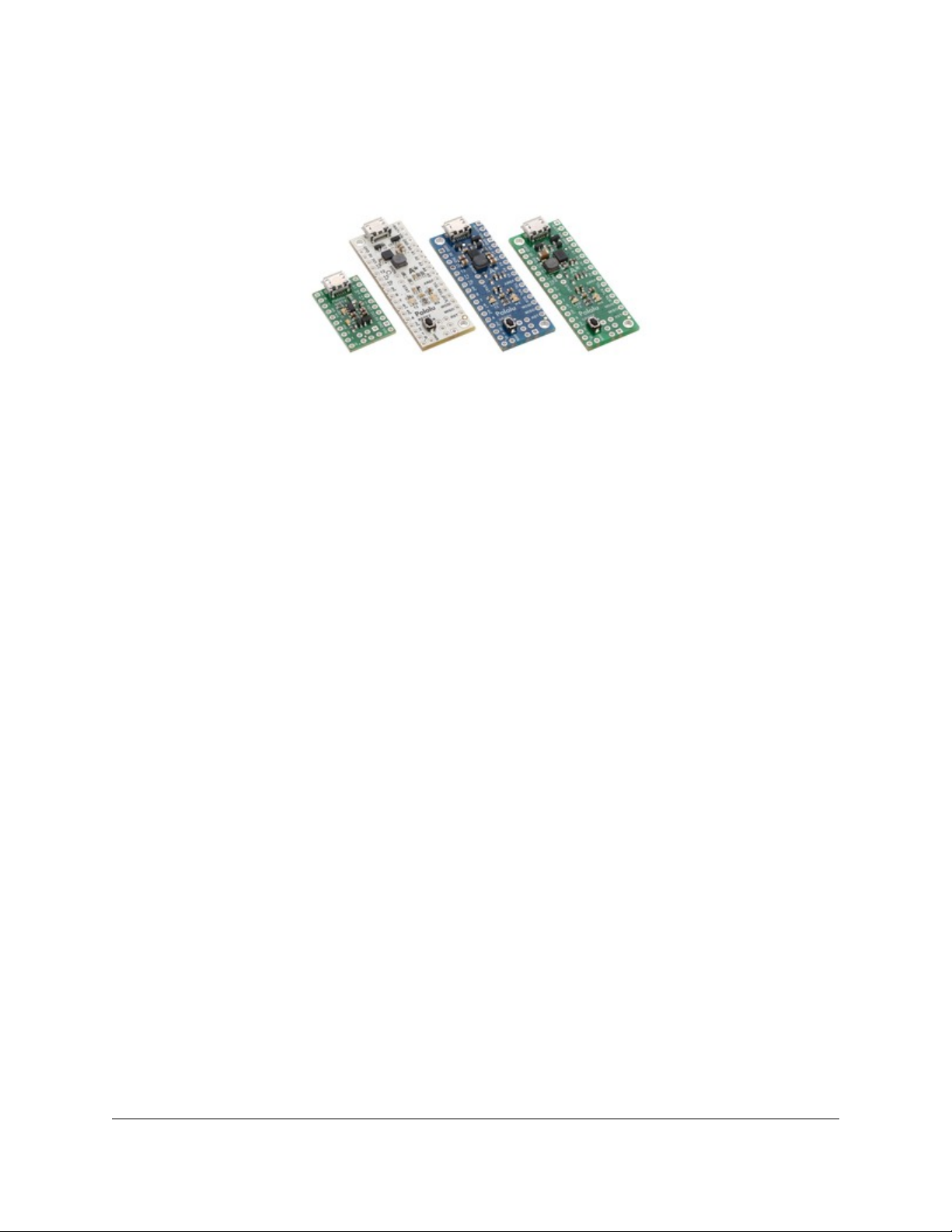
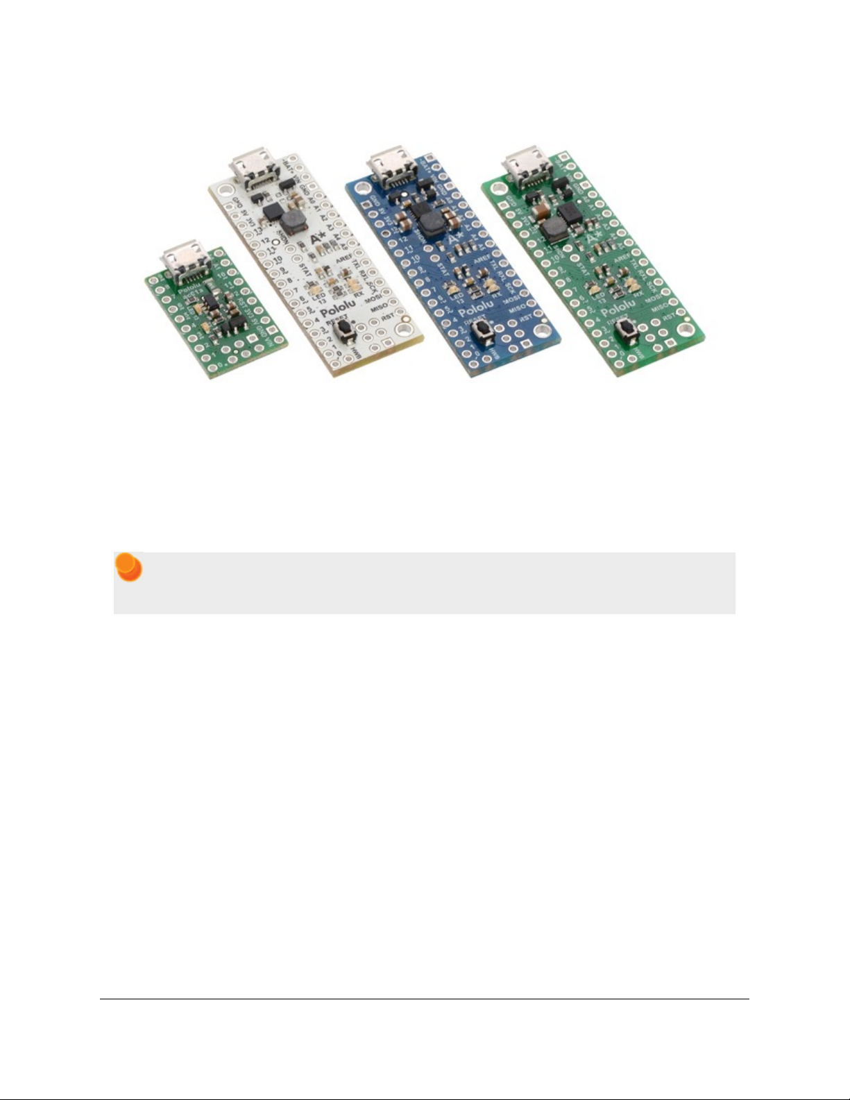
1. Overview
The Pololu A-Star 32U4 family of products.
The Pololu A-Star 32U4 microcontroller boards are general-purpose programmable modules based on Atmel’s
ATmega32U4 AVR microcontroller, which has 32 KB of flash program memory, 2.5 KB of RAM, and builtin USB functionality. Each A-Star (abbreviated A*) adds onboard components and connectors that support the
microcontroller and make it easier to use. The boards feature USB interfaces and ship with a preloaded Arduinocompatible bootloader, and we provide a software add-on that enables them to be easily programmed from the
Arduino environment. The following sections of this user’s guide discuss each A-Star in more detail.
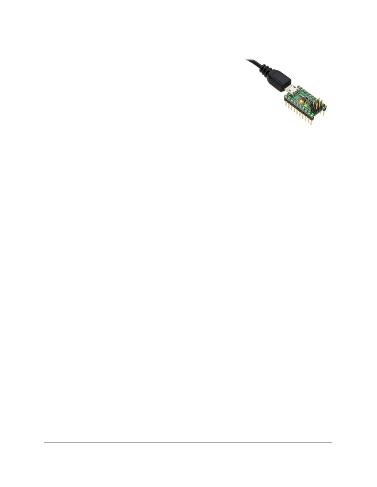
A USB A to Micro-B cable [http://www.pololu.com/product/2072] (not included) is required to connect an
A-Star 32U4 to a computer.
Features
• Programmable 16 MHz Atmel ATmega32U4 AVR microcontroller
◦ 32 KB flash (4 KB used by bootloader, leaving 28 KB available for user program by default)
◦ 2.5 KB SRAM
◦ 1 KB EEPROM
◦ Native full-speed USB (12 Mbps)
• Preloaded with Arduino-compatible bootloader
• Can be powered from USB or external source regulated to 5 V by onboard regulator
• Reverse-voltage protection on external power input
• 6-pin ISP header for use with an external programmer [http://www.pololu.com/product/1300]
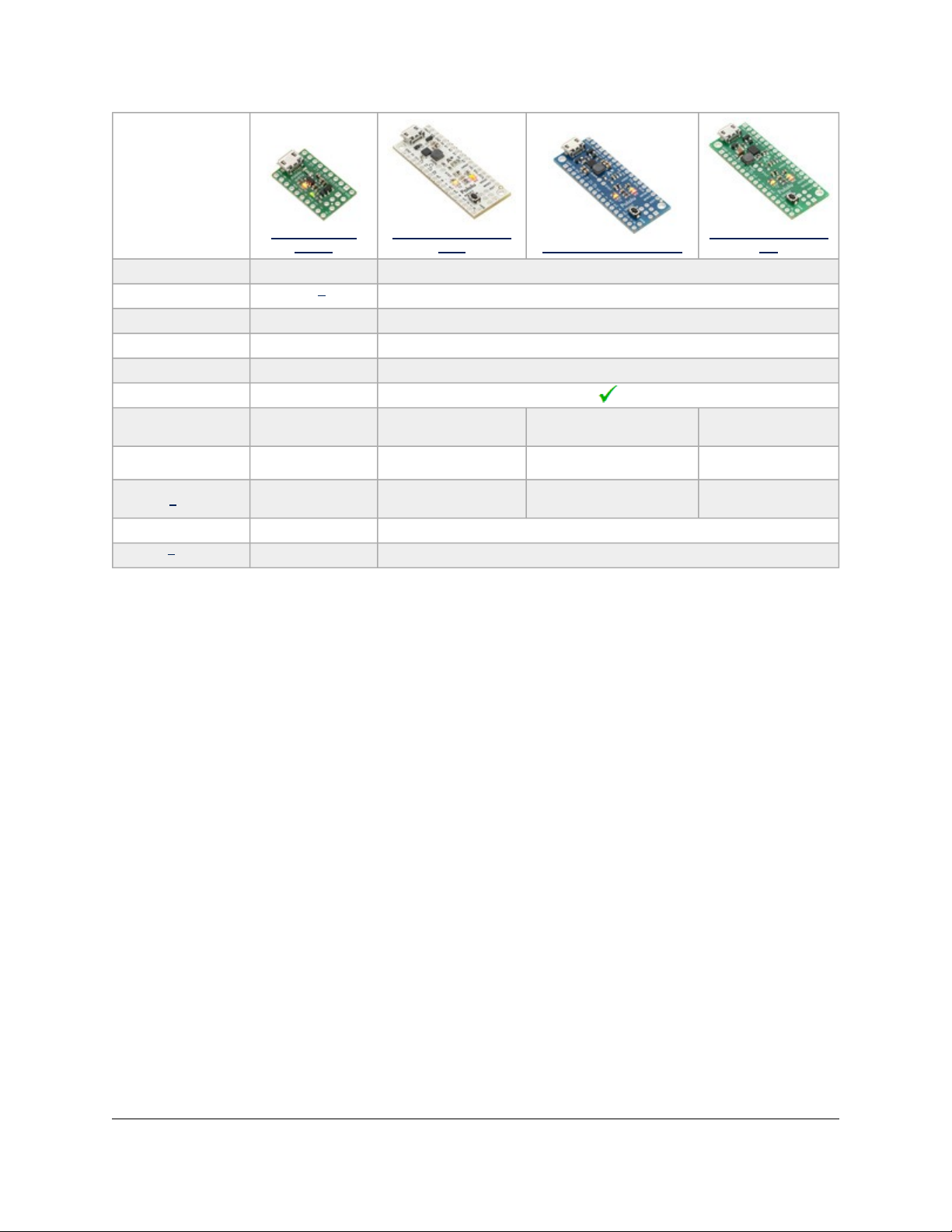
A-Star comparison table
1. Overview Page 2 of 30
Page 3
Pololu A-Star 32U4 User’s Guide © 2001–2014 Pololu Corporation
A-Star 32U4
Micro
Microcontroller: ATmega32U4 ATmega32U4
User I/O lines: 15
PWM outputs: 7 7
Analog inputs: 8 12
User LEDs: 2 3
Reset button:
Operating
voltage:
Regulator type: linear switching step-up
Regulated
current2:
Dimensions: 1″ × 0.6″ 1.9″ × 0.7″
Weight3: 1.3 g 3.4 g
1
Three extra digital I/O lines are accessible through the ISP header.
2
These values are rough approximations for comparison purposes. Available current depends on input voltage,
current consumed by the board, ambient conditions, and regulator topology. See product documentation and
performance graphs for details.
3
Without included optional headers.
1
5.5 V to 15 V 0.5 V to 5.5 V 2.7 V to 11.8 V 5 V to 36 V
100 mA 500 mA 1000 mA 500 mA
A-Star 32U4 Mini
ULV A-Star 32U4 Mini LV
switching step-up/step-
26
down
A-Star 32U4 Mini
SV
switching step-down
1.1. Supported operating systems
The A-Star 32U4 boards can be programmed using any operating system that supports the Arduino environment. We
have tested the A-Stars, our Arduino software add-on, and the Arduino IDE on Microsoft Windows 8.1, 8, 7, Vista,
XP (with Service Pack 3), Linux, and Mac OS X.
1. Overview Page 3 of 30
Page 4
Pololu A-Star 32U4 User’s Guide © 2001–2014 Pololu Corporation
2. Contacting Pololu
We would be delighted to hear from you about any of your projects and about
your experience with the Pololu A-Stars. You can contact us
[http://www.pololu.com/contact] directly or post on our forum
[http://forum.pololu.com/]. Tell us what we did well, what we could improve,
what you would like to see in the future, or anything else you would like to
say!
2. Contacting Pololu Page 4 of 30
Page 5
Pololu A-Star 32U4 User’s Guide © 2001–2014 Pololu Corporation
3. A-Star 32U4 Micro
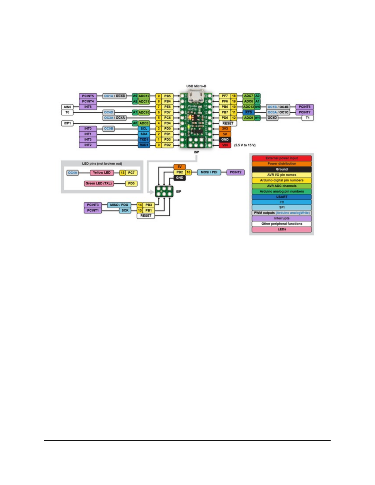
3.1. A-Star 32U4 Micro pinout and components
Pinout
The diagram above identifies the I/O and power pins on the A-Star 32U4 Micro; it is also available as a printable
PDF [http://www.pololu.com/file/download/a-star-32u4-micro-pinout.pdf?file_id=0J796] (409k pdf). For more information about
the ATmega32U4 microcontroller on this board, see Atmel’s ATmega32U4 documentation [http://www.atmel.com/
devices/atmega32u4.aspx].
Printed on the A* circuit board are indicators that you can use to quickly identify each pin’s capabilities: a triangle
next to the pin means it can be used as an analog input, and a square wave symbol under the pin number means it can
be used as a PWM output.
LEDs
The A-Star 32U4 Micro has two indicator LEDs.
The yellow LED is connected to Arduino pin 13, or PC7. You can drive this pin high in a user program to turn this
LED on. The A-Star 32U4 Bootloader [http://www.pololu.com/docs/0J61/7] fades this LED on and off while it is waiting
for a sketch to be loaded.
The green LED is connected to PD5 and lights when the pin is driven low. While the board is running the A-Star
32U4 Bootloader or a program compiled in the Arduino environment, it will flash this LED when it is transmitting
data via the USB connection.
Connectors
The A-Star 32U4 includes a USB Micro-B connector that can be used to connect to a computer’s USB port via a USB
A to Micro-B cable [http://www.pololu.com/product/2072] (not included). The USB connection can be used to transmit
3. A-Star 32U4 Micro Page 5 of 30
Page 6

Pololu A-Star 32U4 User’s Guide © 2001–2014 Pololu Corporation
and receive data from the computer, and a preloaded USB bootloader makes it possible to program the board over
USB. The USB connection can also provide power to the A-Star.
The board also has a 6-pin ISP header that allows it to be programmed with an external programmer, such as our
USB AVR programmer [http://www.pololu.com/product/1300]. Pin 1 of the header is indicated with a small white dot and
has an octagonal shape. Three of the pins on this header can be used as an SPI interface or as general-purpose digital
I/O, as shown in the pinout diagram. In the Arduino environment, you can refer to these three pins using either their
pin numbers or the names of their SPI functions (which are defined as aliases); for example, digitalRead(15) and
digitalRead(SCK) are equivalent.
Power
The A-Star 32U4 Micro can either be powered directly from the USB 5 V supply or from a separate source on the
VIN pin. The board features a power selection circuit that allows both USB and VIN to be connected at the same
time; if this is done, the A-Star will draw power from VIN.
USB power input: The A-Star can be powered from the USB 5 V bus voltage (VBUS) if it is connected to a USB
cable. It will draw power from USB only if VIN is disconnected. A resettable PTC fuse on VBUS makes it less likely
for the A-Star (and the connected computer or other device) to be damaged if too much current is drawn from the
USB connection.
VIN power input: The A-Star can be powered from VIN if you connect a 5.5 V to 15 V power supply (such as a
battery or wall power adapter) to the VIN and GND pins, with the positive terminal connected to VIN.
When powering the A-Star 32U4 Micro from VIN, a minimum voltage of 5.5 V is required to ensure that
the board’s 5 V supply is stable. Even if power is being provided to the A-Star via USB, connecting a
voltage higher than 0 V but lower than 5.5 V to VIN is not recommended, as this can interfere with the
power selection circuit and cause the 5 V line to drop (potentially triggering a brown-out reset).
5V power output: This pin provides access to the board’s 5 V supply, which comes from either the USB 5 V bus
voltage or a low-dropout (LDO) regulator on VIN, depending on which power source is connected. The regulator can
supply up to 100 mA, although some of this is used by the board itself (typically about 25 mA) or used to provide
current for the GPIO pins or 3.3 V power output (see below).
3V3 power output: This pin gives access to the output of the internal 3.3 V regulator inside the ATmega32U4.
The microcontroller uses this regulated voltage for USB signaling, but up to about 50 mA is available for powering
external circuits or devices.
When the A-Star 32U4 Micro is being powered through VIN, the sum of the 5V output current, 3V3 output current,
GPIO output current, and current used by the board itself should not exceed the 100 mA that the regulator can provide.
3. A-Star 32U4 Micro Page 6 of 30
Page 7
Pololu A-Star 32U4 User’s Guide © 2001–2014 Pololu Corporation
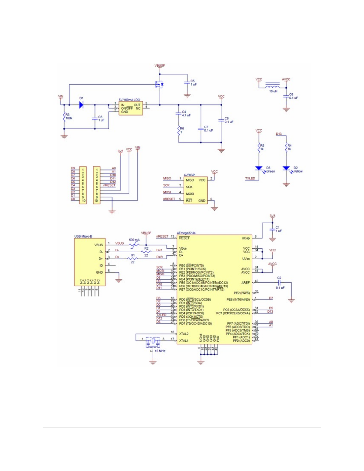
3.2. A-Star 32U4 Micro schematic and dimensions
Schematic diagram
Pololu A-Star 32U4 Micro schematic diagram.
This schematic is also available as a PDF: A-Star 32U4 Micro schematic diagram [http://www.pololu.com/file/download/
pololu-a-star-32u4-micro-schematic-diagram.pdf?file_id=0J742] (253k pdf).
3. A-Star 32U4 Micro Page 7 of 30
Page 8

Pololu A-Star 32U4 User’s Guide © 2001–2014 Pololu Corporation
Dimension diagram
A dimension diagram of the A-Star 32U4 Micro is available as a PDF: A-Star 32U4 Micro dimension diagram
[http://www.pololu.com/file/download/pololu-a-star-32u4-micro-dimension-diagram.pdf?file_id=0J747] (255k pdf).
3. A-Star 32U4 Micro Page 8 of 30
Page 9
Pololu A-Star 32U4 User’s Guide © 2001–2014 Pololu Corporation
4. A-Star 32U4 Mini
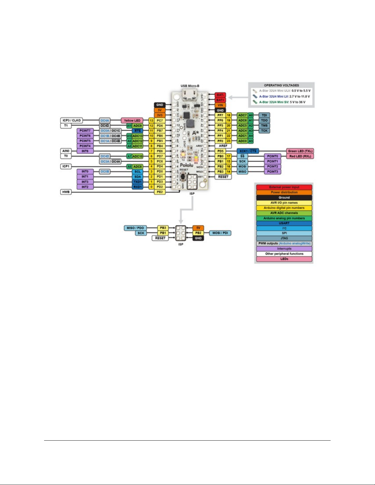
4.1. A-Star 32U4 Mini pinout and components
Pinout
This diagram identifies the I/O and power pins on the A-Star 32U4 Mini (ULV, LV, and SV versions); it is
also available as a printable PDF [http://www.pololu.com/file/download/a-star-32u4-mini-pinout.pdf?file_id=0J784] (269k pdf).
For more information about the ATmega32U4 microcontroller and its peripherals, see Atmel’s ATmega32U4
documentation.
Printed on the A* circuit board are indicators that you can use to quickly identify each pin’s capabilities: a triangle
next to the pin means it can be used as an analog input, and a square wave symbol under the pin number means it can
be used as a PWM output.
LEDs
The A-Star 32U4 Mini has three indicator LEDs.
The yellow LED is connected to Arduino pin 13, or PC7. You can drive this pin high in a user program to turn this
LED on. The A-Star 32U4 Bootloader [http://www.pololu.com/docs/0J61/7] fades this LED on and off while it is waiting
for a sketch to be loaded.
The green LED is connected to the pin labeled TXL, or PD5, and lights when the pin is driven low. While the board
is running the A-Star 32U4 Bootloader or a program compiled in the Arduino environment, it will flash this LED
when it is transmitting data via the USB connection.
4. A-Star 32U4 Mini Page 9 of 30
Page 10

Pololu A-Star 32U4 User’s Guide © 2001–2014 Pololu Corporation
The red LED is connected to the pin labeled RXL, or PB0, and lights when the pin is driven low. While the board is
running the A-Star 32U4 Bootloader or a program compiled in the Arduino environment, it will flash this LED when
it is receiving data via the USB connection.
Connectors
The A-Star 32U4 includes a USB Micro-B connector that can be used to connect to a computer’s USB port via a USB
A to Micro-B cable [http://www.pololu.com/product/2072] (not included). The USB connection can be used to transmit
and receive data from the computer, and a preloaded USB bootloader makes it possible to program the board over
USB. The USB connection can also provide power to the A-Star.
The board also has a 6-pin ISP header that allows it to be programmed with an external programmer, such as our
USB AVR programmer [http://www.pololu.com/product/1300]. Pin 1 of the header is indicated with a small dot and has
an octagonal shape.
Power
The A-Star 32U4 Mini can either be powered directly from the USB 5 V supply or from an external voltage source,
which is regulated to 5 V by its onboard switching regulator.
The board’s power selection circuit uses the TPS2113A power multiplexer [http://www.pololu.com/product/2596] from
Texas Instruments to choose whether its 5 V supply is sourced from USB or an external supply via the regulator,
allowing both sources to be connected at the same time and enabling the A-Star to safely and seamlessly transition
between them. The TPS2113A is configured to select external power unless the regulator output falls below about
4.5 V. If this happens, it will select the higher of the two sources, which will typically be the USB 5 V bus voltage if
the A* is connected to USB. The currently selected source is indicated by the STAT pin in the middle of the board;
this pin is an open-drain output that is low if the external power source is selected and high-impedance if the USB
supply is selected. The current limit of the TPS2113A is set to about 1.9 A. For more information about the power
multiplexer, see the TPS2113A datasheet [http://www.pololu.com/file/download/tps2113a.pdf?file_id=0J771] (1MB pdf).
In some situations, it might be undesirable for the A-Star 32U4 Mini to draw power from an external source when it
is connected to USB. If this is the case, the regulator can be disabled by driving the regulator shutdown pin, SHDN,
high; this shuts down the regulator and causes the power mux to fall back to USB power. For example, this could
allow a battery-powered device to turn off the regulator and avoid draining its battery while it is connected to a
computer.
The input voltage range of the regulator depends on the particular version of the A-Star 32U4 Mini:
• ULV: 0.5 V to 5.5 V (see Section 4.2 for regulator details)
• LV: 2.7 V to 11.8 V (see Section 4.3 for regulator details)
• SV: 5 V to 36 V (see Section 4.4 for regulator details)
Reverse-protected power inputs: The BAT+ and BAT- pins are power inputs with reverse-voltage protection. These
are the recommended pins to use when connecting an external power supply because they allow the A-Star’s reversevoltage protection circuit to help prevent it from being damaged by accidentally-reversed power connections.
VIN power output (or alternative input): When power is supplied through the BAT pins, the VIN pin can be used
as an output to supply reverse-protected power to other devices. Alternatively, the external supply can be connected
directly between VIN and GND, bypassing the reverse-voltage protection.
5V power output: This pin provides access to the board’s 5 V supply, which comes from either the USB 5 V bus
voltage or the onboard switching regulator, depending on which power sources are connected and enabled. Note that
4. A-Star 32U4 Mini Page 10 of 30
Page 11

Pololu A-Star 32U4 User’s Guide © 2001–2014 Pololu Corporation
some of the available current on the 5 V line is used by the board itself (typically about 30 mA) or used to provide
current for the GPIO pins or 3.3 V power output (see below).
3V3 power output: This pin gives access to the output of the internal 3.3 V regulator inside the ATmega32U4.
The microcontroller uses this regulated voltage for USB signaling, but up to about 50 mA is available for powering
external circuits or devices.
When the A-Star 32U4 Mini is being powered through VIN, the sum of the 5V output current, 3V3 output current,
GPIO output current, and current used by the board itself should not exceed the maximum current that the regulator
can provide; see the following sections for details about the regulator on each version.
4.2. A-Star 32U4 Mini ULV regulator
The A-Star Mini ULV can be powered from a 0.5 V to 5.5 V
external source. The input voltage is regulated to 5 V by a
TPS61202 switching step-up (boost) converter from Texas
Instruments. (We also make a standalone regulator
[http://www.pololu.com/product/2562] based on this integrated circuit.)
The regulator’s low minimum input voltage makes it possible to
power this A* with 1 to 3 NiMH, NiCd, or alkaline cells or from a
single lithium cell. Unlike standard boost regulators, the TPS61202
also features a linear down-regulation mode that is automatically
enabled when the input voltage exceeds 5 V, allowing it to handle
input voltages as high as 5.5 V.
As shown in the left graph below, the ULV’s switching regulator has
an efficiency – defined as (Power out)/(Power in) – of 70% to 90%
for most combinations of input voltage and load.
A-Star 32U4 Mini ULV, bottom view with
dimensions.
The A-Star’s components, including the microcontroller and LEDs, draw 30 mA to 40 mA in typical applications.
The rest of the regulator’s achievable output current, which depends on input voltage as well as ambient conditions,
can be used to power other devices. The right graph above shows output currents at which the voltage regulator’s
4. A-Star 32U4 Mini Page 11 of 30
Page 12

Pololu A-Star 32U4 User’s Guide © 2001–2014 Pololu Corporation
over-temperature protection typically kicks in after a few seconds. These currents represent the limit of the regulator’s
capability and cannot be sustained for long periods; a good estimate for the maximum continuous regulator output
current is 60% to 70% of the values shown in the graph.
4.3. A-Star 32U4 Mini LV regulator
The A-Star Mini LV can be powered from a 2.7 V to 11.8 V
external source. The input voltage is regulated to 5 V by a
TPS63061 switching step-up/step-down (buck-boost) converter
from Texas Instruments. (We also make a standalone regulator
[http://www.pololu.com/product/2123] based on this integrated circuit.)
The regulator’s flexibility in input voltage is especially well-suited
for battery-powered applications in which the battery voltage begins
above 5 V and drops below 5 V as the battery discharges. Without
the typical restriction on the battery voltage staying above 5 V
throughout its life, a wider range of battery types can be considered.
For example:
• A 4-cell battery holder, which might have a 6 V output with
fresh alkalines or a 4.0 V output with partially discharged NiMH
cells, can be used to power this A*.
• A disposable 9 V battery powering the board can be
discharged to under 3 V instead of cutting out at 6 V, as with
typical linear or step-down regulators.
A-Star 32U4 Mini LV, bottom view with
dimensions.
As shown in the left graph below, the LV’s switching regulator has
an efficiency – defined as (Power out)/(Power in) – of 80% to 90%
for most combinations of input voltage and load.
The A-Star’s components, including the microcontroller and LEDs, draw 30 mA to 40 mA in typical applications.
The rest of the regulator’s achievable output current, which depends on input voltage as well as ambient conditions,
can be used to power other devices. The right graph above shows output currents at which the voltage regulator’s
over-temperature protection typically kicks in after a few seconds. These currents represent the limit of the regulator’s
capability and cannot be sustained for long periods; a good estimate for the maximum continuous regulator output
current is 60% to 70% of the values shown in the graph.
4. A-Star 32U4 Mini Page 12 of 30
Page 13

Pololu A-Star 32U4 User’s Guide © 2001–2014 Pololu Corporation
4.4. A-Star 32U4 Mini SV regulator
The A-Star Mini SV can be powered from a 5 V to 36 V external
source. The input voltage is regulated to 5 V by a 500 mA ISL85415
switching step-down (buck) converter from Intersil. (We also make
a standalone regulator [http://www.pololu.com/product/2843] based on
this integrated circuit.)
As shown in the left graph below, the SV’s switching regulator has
an efficiency – defined as (Power out)/(Power in) – of 80% to 95%
for most combinations of input voltage and load.
A-Star 32U4 Mini SV, bottom view with
dimensions.
The A-Star’s components, including the microcontroller and LEDs, draw 30 mA to 40 mA in typical applications.
The rest of the regulator’s achievable output current, which depends on input voltage as well as ambient conditions,
can be used to power other devices. The right graph above shows output currents at which the voltage regulator’s
over-temperature protection typically kicks in after a few seconds. These currents represent the limit of the regulator’s
capability and cannot be sustained for long periods; a good estimate for the maximum continuous regulator output
current is 60% to 70% of the values shown in the graph or 500 mA, whichever is lower (the regulator is not rated for
operation above 500 mA).
4.5. A-Star 32U4 Mini schematic and dimensions
Schematic diagram
The schematic diagram for the A-Star 32U4 Minis is available as a PDF: A-Star 32U4 Mini schematic diagram
[http://www.pololu.com/file/download/a-star-32u4-mini-schematic.pdf?file_id=0J780] (451k pdf).
4. A-Star 32U4 Mini Page 13 of 30
Page 14

Pololu A-Star 32U4 User’s Guide © 2001–2014 Pololu Corporation
Dimension diagrams
Dimension diagrams for the A-Star 32U4 Minis are available as PDFs:
• A-Star 32U4 Mini ULV dimension diagram [http://www.pololu.com/file/download/ac02a-
dimensions.pdf?file_id=0J781] (274k pdf)
• A-Star 32U4 Mini LV dimension diagram [http://www.pololu.com/file/download/ac02b-dimensions.pdf?file_id=0J782]
(292k pdf)
• A-Star 32U4 Mini SV dimension diagram [http://www.pololu.com/file/download/ac02c-dimensions.pdf?file_id=0J783]
(291k pdf)
4. A-Star 32U4 Mini Page 14 of 30
Page 15

Pololu A-Star 32U4 User’s Guide © 2001–2014 Pololu Corporation
5. Getting started
5.1. Installing Windows drivers
If you use Windows XP, you will need to have either Service Pack 3 [http://www.microsoft.com/downloads/
details.aspx?FamilyId=68C48DAD-BC34-40BE-8D85-6BB4F56F5110] or Hotfix KB918365 installed before
installing the A-Star drivers. Some users who installed the hotfix have reported problems which were
solved by upgrading to Service Pack 3, so we recommend Service Pack 3 over the hotfix.
Before you connect your Pololu A-Star 32U4 to a computer running Microsoft Windows, you must install its drivers:
1. Download the A-Star Software and Drivers [http://www.pololu.com/file/download/a-star-1.0.1.zip?file_id=0J743]
(98k zip) and extract the ZIP file to a temporary folder on your computer. These files are also available from the
A-Star repository on GitHub [https://github.com/pololu/a-star].
2. Open the “drivers” folder. Right-click on “a-star.inf” and select “Install”.
3. Windows will ask you whether you want to install the drivers. Click “Install” (Windows 8, 7, and Vista) or
“Continue Anyway” (Windows XP).
4. Windows will not tell you when the installation is complete, but it should be done after a few seconds.
Windows 8, Windows 7, and Windows Vista users: After installing the drivers, your computer should automatically
recognize the A-Star when you connect it via USB. No further action from you is required. However, the first time
5. Getting started Page 15 of 30
Page 16

Pololu A-Star 32U4 User’s Guide © 2001–2014 Pololu Corporation
you connect an A-Star to your computer, Windows will take several seconds to recognize the device and configure
itself properly. The first time you program the A-Star, Windows will again take several seconds to recognize the AStar’s USB bootloader, and this could cause the programming operation to fail the first time. Also, Windows will
need to re-recognize the A-Star and the bootloader if you connect the board to another USB port that it has not been
connected to before.
Windows XP users: After installing the drivers, you will need to follow steps 5–9 for each new A-Star you connect
to your computer. You will also need to follow these steps the first time you attempt to program the A-Star in order
to make Windows recognize the bootloader, and when you connect the A-Star to a different USB port that it has not
been connected to before.
5. Connect the A-Star to your computer’s USB port.
6. When the “Found New Hardware Wizard” is displayed, select “No, not this time” and click “Next”.
7. On the second screen of the “Found New Hardware Wizard”, select “Install the software automatically” and
click “Next”.
8. Windows XP will warn you again that the driver has not been tested by Microsoft and recommend that you
stop the installation. Click “Continue Anyway”.
9. When you have finished the “Found New Hardware Wizard”, click “Finish”.
5.2. Programming using the Arduino IDE
The Pololu A-Star 32U4 boards can be programmed from the
popular Arduino integrated development environment (IDE). The
Arduino IDE is a cross-platform, open source application that
integrates a C++ code editor, the GNU C++ compiler, and a
program upload utility. To get started programming your A-Star
with the Arduino IDE, follow these steps:
1. Download the Arduino IDE from the Arduino Download
page [http://arduino.cc/en/Main/Software] and install it. You can
download either the 1.0.x version or the 1.5.x version; the A-Stars
support both.
2. If you have not done so already, download the A-Star
Software and Drivers [http://www.pololu.com/file/download/a-
star-1.0.1.zip?file_id=0J743] (98k zip). These files are also available
from the A-Star repository on GitHub [https://github.com/pololu/a-
star]. Copy the “pololu” folder from the downloaded “add-on”
folder into the [sketchbook location]/hardware folder. You can
see the sketchbook location in the Arduino IDE Preferences
dialog, which is available from the File menu. For a typical user,
the sketchbook location will be a folder named Arduino inside the
Documents folder. For a typical user running a recent version of
Windows, the “pololu” folder should be installed in this location:
C:\Users\<username>\Documents\Arduino\hardware\pololu
Programming the A-Star 32U4 from the
Arduino IDE.
If the “Arduino” or “hardware” directories do not exist yet, you will need to create them.
3. Close the Arduino IDE if it is open, and then restart it.
5. Getting started Page 16 of 30
Page 17

Pololu A-Star 32U4 User’s Guide © 2001–2014 Pololu Corporation
4. In the Tools > Board menu, select the “Pololu A-Star 32U4” entry. If you do not see the A-Star listed in
the Board menu, then the add-on is probably not installed correctly. Try doing step 2 again and restarting the
Arduino IDE.
Selecting the Pololu A-Star 32U4 in the Boards menu.
5. In the Tools > Port menu, select the port for the A-Star. On Windows you can determine what COM port the
A-Star is assigned to by looking at the “Ports (COM & LPT)” section of the Device Manager. On Linux, the port
name will begin with “/dev/ttyACM”. On Mac OS X, the port name will begin with “/dev/tty.usbmodem”.
Windows 8 device manager showing the A-Star’s virtual COM port.
6. Open up the “Blink” Arduino example, which can be found under File > Examples > 01.Basics > Blink.
The code in this example will make the A-Star blink its yellow LED. When you select the Blink example, a new
Arduino IDE window will open up. It is OK to close the first window.
5. Getting started Page 17 of 30
Page 18

Pololu A-Star 32U4 User’s Guide © 2001–2014 Pololu Corporation
Selecting the Blink example in the Arduino IDE.
7. Press the “Upload” button to compile the sketch and upload it to the A-Star. If everything goes correctly, you
will see the message “Done uploading” appear near the bottom of the window. If you are using Windows and
you have not previously programmed an A-Star on this USB port, then Windows might take several seconds to
recognize the A-Star bootloader. The bootloader times out after 8 seconds and goes back to running the sketch,
so the upload might fail if Windows does not recognize it quickly enough. If this happens, try again. If you are
using Windows XP and have not programmed an A-Star on this USB port, you will have to go through the Found
New Hardware Wizard again as described in Section 5.1, but the second time you try to upload it should work. If
the Arduino IDE has trouble connecting to the port or using it, try unplugging the A-Star, closing any programs
that might be using the serial port, restarting the Arduino IDE, and then plugging the A-Star back in.
5. Getting started Page 18 of 30
Page 19

Pololu A-Star 32U4 User’s Guide © 2001–2014 Pololu Corporation
Uploading a sketch to the A-Star using the Arduino IDE.
8. If you uploaded the Blink sketch, then the A-Star’s yellow LED should be blinking once every two seconds.
However, we ship the A-Stars with that same example already programmed onto it, so you might not be
convinced that anything has changed. Try changing the delay values in the sketch to something else and
uploading again to see if you can change the speed of the LED.
The A-Star 32U4 boards are similar enough to the Arduino Leonardo that you do not actually have to
install the add-on. If you want to, you can just select the “Arduino Leonardo” board in the Arduino
IDE. Note that if you upload a sketch to the A-Star this way, your computer will then recognize it as a
Leonardo (for example, its entry in the Windows Device Manager will display “Arduino Leonardo”).
After you succeed in programming the A-Star from the Arduino IDE, there are many resources you can use to learn
more:
• The Arduino IDE has many examples [http://arduino.cc/en/Tutorial/HomePage] that can run on A-Stars.
• The Arduino website has a Language Reference [http://arduino.cc/en/Reference/HomePage], a wiki called the The
Arduino Playground [http://playground.arduino.cc/], and other resources.
• The A-Star 32U4 boards are similar to the Arduino Leonardo [http://www.pololu.com/product/2192] and Arduino
Micro [http://www.pololu.com/product/2188], so you can search the Internet for relevant projects that use one of those
boards.
• Section 9 lists many more resources.
5. Getting started Page 19 of 30
Page 20

Pololu A-Star 32U4 User’s Guide © 2001–2014 Pololu Corporation
5.3. Programming using avr-gcc and AVRDUDE
This section explains how to program the A-Star boards using the avr-gcc toolchain and AVRDUDE. This section is
intended for advanced users who do not want to use the Arduino IDE as described in Section 5.2.
Getting the prerequisites
If you are using Windows, we recommend downloading WinAVR [http://winavr.sourceforge.net/], which contains the avr-
gcc toolchain and a command-line utility called AVRDUDE [http://www.nongnu.org/avrdude/] that can be used to upload
programs to the A-Star bootloader. If the version of GNU Make that comes with WinAVR crashes on your computer,
we recommend using the Pololu version of GNU Make [https://github.com/pololu/make/releases].
If you are using Mac OS X, we recommend downloading the CrossPack for AVR Development [http://www.obdev.at/
products/crosspack].
If you are using Linux, you will need to install avr-gcc, avr-libc, and AVRDUDE. Ubuntu users can get the required
software by running:
sudo apt-get install gcc-avr avr-libc avrdude
After you have installed the prerequisites, open a command prompt and try running these commands to make sure all
the required utilities are available:
avr-gcc -v
avr-objcopy -V
make -v
avrdude
If any of those commands fail, make sure the desired executable is installed on your computer and make sure that it
is in a directory listed in your PATH environment variable.
Compiling an example program
Copy the following code to a file named “main.c”:
#define F_CPU 16000000
#include <avr/io.h>
#include <util/delay.h>
int main()
{
DDRC |= (1 << DDC7); // Make pin 13 be an output.
while(1)
{
PORTC |= (1 << PORTC7); // Turn the LED on.
_delay_ms(500);
PORTC &= ~(1 << PORTC7); // Turn the LED off.
_delay_ms(500);
}
}
In the same folder, create a file named “Makefile” with the following contents:
PORT=\\\\.\\USBSER000
MCU=atmega32u4
CFLAGS=-g -Wall -mcall-prologues -mmcu=$(MCU) -Os
LDFLAGS=-Wl,-gc-sections -Wl,-relax
CC=avr-gcc
TARGET=main
OBJECT_FILES=main.o
5. Getting started Page 20 of 30
Page 21

Pololu A-Star 32U4 User’s Guide © 2001–2014 Pololu Corporation
all: $(TARGET).hex
clean:
%.hex: %.obj
%.obj: $(OBJECT_FILES)
program: $(TARGET).hex
rm -f *.o *.hex *.obj *.hex
avr-objcopy -R .eeprom -O ihex $< $@
$(CC) $(CFLAGS) $(OBJECT_FILES) $(LDFLAGS) -o $@
avrdude -p $(MCU) -c avr109 -P $(PORT) -U flash:w:$(TARGET).hex
Make sure that the PORT variable in the Makefile is set to the name of the A-Star’s virtual serial port. In Windows,
\\\\.\\USBSER000 should work if the A-Star is the only USB device connected that is using the usbser.sys driver, but
you can change it to be the actual name of the COM port (e.g. COM13).
In a command prompt, navigate to the directory with the Makefile and main.c. If you run the command make, the code
should get compiled and produce a file named “main.hex”.
Programming
To program the A-Star, you will need to get it into bootloader mode first. One way to do this is to reset the AVR twice
within 750 ms. The A-Star 32U4 Mini boards have a reset button that can be used to reset the board. On any A-Star
board, a pushbutton can be connected between the GND and RST pins to serve as a reset button, or you can use a
wire. Once the A-Star is in bootloader mode, quickly run the command make program to program the A-Star. If you
wait longer than 8 seconds, the A-Star bootloader will exit and the AVR will go back to running the user program.
5. Getting started Page 21 of 30
Page 22

Pololu A-Star 32U4 User’s Guide © 2001–2014 Pololu Corporation
6. The A-Star 32U4 USB interface
The A-Star 32U4 boards are based on a single AVR ATmega32U4 microcontroller that runs the user program and
also handles the USB connection to the computer. The AVR has a full-speed USB transceiver built into it and can be
programmed to present almost any type of USB device interface to the computer.
USB is an asymmetric system that consists of a single “host” connected to multiple “devices”. The host is typically a
personal computer. The ATmega32U4 can only act as a USB device, so an A-Star cannot be connected to other USB
devices; it can only be connected to a host such as your computer.
Programming an A-Star using the Arduino IDE as described in Section 5.2 will automatically configure it as a
composite device with a single virtual serial port and a human interface device (HID) with a keyboard and mouse.
Since we preload an example Arduino sketch on each A-Star before it ships, this is the default USB configuration of
the A-Star.
On a Windows computer, you can see the virtual serial port by going to your computer’s Device Manager and
expanding the “Ports (COM & LPT)” list. You should see a COM port labeled “Pololu A-Star 32U4”. In parentheses
after the name, you will see the name of the port (e.g. “COM3” or “COM4”). Windows will assign a different COM
port number to the A-Star depending on what USB port you plug it into and whether it is in bootloader mode or not. If
you need to change the COM port number assigned to the A-Star, you can do so using the Device Manager. Doubleclick on the COM port to open its properties dialog, and click the “Advanced…” button in the “Port Settings” tab.
From this dialog you can change the COM port assigned to the A-Star.
Windows 8 device manager showing the A-Star’s virtual COM port.
On a Windows computer, you can see the rest of the A-Star’s USB interface by going to the Device Manager, selecting
View > Devices by connection, and then expanding entries until you find the “Pololu A-Star 32U4” COM port. Near
it, you should see the parent composite device and the human interface device.
6. The A-Star 32U4 USB interface Page 22 of 30
Page 23

Pololu A-Star 32U4 User’s Guide © 2001–2014 Pololu Corporation
The Windows 8 Device Manager in “Devices by connection” mode, showing that
the A-Star is a composite device.
On a Linux computer, you can see details about the A-Star’s USB interface by running lsusb -v -d 1ffb: in a
Terminal. The virtual serial port can be found by running ls /dev/ttyACM* in a Terminal.
On a Mac OS X computer, the virtual serial port can be found by running ls /dev/tty.usbmodem* in a Terminal.
You can send and receive bytes from an A-Star’s virtual serial port using any terminal program that supports
serial ports. Some examples are the Serial Monitor in Arduino IDE, the Pololu Serial Transmitter Utility
[http://www.pololu.com/docs/0J23], Br@y Terminal [http://sites.google.com/site/terminalbpp/], PuTTY
[http://www.chiark.greenend.org.uk/~sgtatham/putty/], TeraTerm [http://ttssh2.sourceforge.jp/], Kermit [http://www.columbia.edu/
kermit/ck80.html], and GNU Screen [http://www.gnu.org/software/screen/]. Many computer programming environments also
support sending and receiving bytes from a serial port.
6. The A-Star 32U4 USB interface Page 23 of 30
Page 24

Pololu A-Star 32U4 User’s Guide © 2001–2014 Pololu Corporation
7. The A-Star 32U4 Bootloader
The A-Star 32U4 boards come with a USB bootloader that can be used in conjunction with the Arduino IDE or
AVRDUDE to load new programs onto an A-Star. This section documents some technical details of the bootloader
for advanced users who want to better understand how it works. If you just want to get started using your A-Star, it is
fine to skip this section.
The A-Star 32U4 Bootloader, which is used on all A-Star 32U4 boards, is based on the Caterina bootloader
[https://github.com/arduino/Arduino/tree/master/hardware/arduino/bootloaders/caterina], which is the bootloader used on the
Arduino Leonardo [http://www.pololu.com/product/2192], Arduino Micro [http://www.pololu.com/product/2188] and several
other ATmega32U4 boards. The bootloader is open source and its source code [https://github.com/pololu/a-star/tree/master/
bootloaders/caterina] is available on GitHub. The bootloader occupies the upper four kilobytes of the ATmega32U4’s
program memory, leaving 28 KB for the user program. The bootloader’s USB interface consists of a single virtual
serial port that accepts the programming commands defined in AVR109 [http://www.atmel.com/images/doc1644.pdf]. The
bootloader always runs first immediately after the AVR is reset.
Startup logic
The main difference between the A-Star 32U4 Bootloader and Caterina is in the startup logic. This is the part of the
bootloader that runs immediately after the AVR is reset, and it decides whether to run the user program or run the rest
of the bootloader. The startup logic of the Caterina bootloader is designed so that when the RST line goes low, the
bootloader will run. This means that if you want to restart your program using the RST line, it will take 8 seconds
before the bootloader times out waiting for an upload and the sketch starts.
The A-Star 32U4 Bootloader has different startup logic that allows you to use the RST line to reset the board with
a smaller delay. If the RST line goes low once, the user program will run after a 750 ms delay. If the RST line goes
low twice within 750 ms, then the bootloader will run. (This behavior is the same as on boards like SparkFun’s Pro
Micro.)
The start-up logic of the A-Star 32U4 Bootloader is shown in the flowchart below:
7. The A-Star 32U4 Bootloader Page 24 of 30
Page 25

Pololu A-Star 32U4 User’s Guide © 2001–2014 Pololu Corporation
The startup logic for the A-Star 32U4 bootloader.
Brown-out detection
Unlike many other ATmega32U4 boards, the A-Stars have brown-out detection enabled. The brown-out threshold is
4.3 V, and if the voltage on VCC goes below this then the AVR will reset. The bootloader was designed so that the
user program can detect brown-out resets. To do so, check to see if the BORF bit in the MCUSR register is set, and
then clear it later. Here is some example code you could put in your setup function for detecting brown-out resets:
7. The A-Star 32U4 Bootloader Page 25 of 30
Page 26

Pololu A-Star 32U4 User’s Guide © 2001–2014 Pololu Corporation
pinMode(13, OUTPUT);
if (MCUSR & (1 << BORF))
{
// A brownout reset occurred. Blink the LED
// quickly for 2 seconds.
for(uint8_t i = 0; i < 10; i++)
{
digitalWrite(13, HIGH);
delay(100);
digitalWrite(13, LOW);
delay(100);
}
}
MCUSR = 0;
7. The A-Star 32U4 Bootloader Page 26 of 30
Page 27

Pololu A-Star 32U4 User’s Guide © 2001–2014 Pololu Corporation
8. Reviving an unresponsive A-Star
In order to load a new program onto your A-Star, you will need to get it into bootloader mode and send programming
commands to it over its virtual serial port using appropriate software. If you are programming the A-Star from the
Arduino IDE, the sketch loaded onto the A-Star will generally support a special USB command for putting the A-Star
mode in bootloader mode, and the Arduino IDE sends that command automatically when you click the Upload button.
However, you might find yourself in a situation where the A-Star is unresponsive and that method will not work. This
can happen for two reasons:
• You accidentally loaded a malfunctioning program onto the A-Star that is incapable of responding to the
special USB command. For example, your program might be stuck in an infinite loop with interrupts disabled.
• You loaded a program which uses a non-standard type of USB interface or no USB interface.
The following sections provide different procedures you can use to revive your A-Star.
8.1. Reviving using the Arduino IDE
This section explains two special methods for programming an A-Star using the Arduino IDE in case your usual
method of programming is not working. These instructions were developed for the Arduino IDE versions 1.0.5-r2 and
1.5.6-r2, and they might need to be modified for future versions.
Reset button
If you have an A-Star 32U4 Micro, you should connect a momentary pushbutton [http://www.pololu.com/product/1400]
between the GND and RST pins to serve as a reset button. The A-Star 32U4 Minis have an on-board reset button
you can use. Alternatively, you can use a wire to temporarily connect GND and RST together instead of using a reset
button.
Resetting the board twice within 750 ms makes the board go into bootloader mode. The bootloader will exit after 8
seconds and try to run the sketch again if it has not started receiving programming commands. To revive the A-Star,
you need to make sure you start sending it programming commands before the 8-second period is over.
In bootloader mode, the yellow LED (the one labeled L) fades in and out. It is useful to look at this LED so you
can know what mode the microcontroller is in. Also, we recommend enabling verbose output during upload using
the Arduino IDE’s “Preferences” dialog. Looking at the LED and looking at the verbose output during the following
procedures will help you understand what is going on.
The uploading-before-bootloader method (Arduino 1.0.x only)
The goal of the uploading-before-bootloader method is to select a non-existent serial port in the Arduino IDE and
then make sure the Arduino IDE enters the uploading phase before the microcontroller goes into bootloader mode.
This method does not work on the Arduino IDE 1.5.6-r2 and later because those versions of the IDE give a fatal error
message if the selected serial port is not present at the beginning of the uploading phase (e.g. “Board at COM7 is not
available.”).
1. Connect the A-Star to your computer via USB.
2. In the “Tools” menu, open the “Board” sub-menu, and select “Pololu A-Star 32U4”.
3. In the “Tools” menu, open the “Port” sub-menu, and check to see if any ports are selected. If the “Port” menu
is grayed out or no ports in it are selected, that is good, and you can skip to step 6.
4. Reset the board twice to get the board into bootloader mode. While the board is in bootloader mode, quickly
select the new serial port that corresponds to the bootloader in the “Port” menu.
8. Reviving an unresponsive A-Star Page 27 of 30
Page 28

Pololu A-Star 32U4 User’s Guide © 2001–2014 Pololu Corporation
5. After 8 seconds, the bootloader will exit and attempt to run the sketch again. Wait for the bootloader to exit.
Verify that either the “Port” menu is grayed out or no ports in it are selected.
6. Click the Upload button. The Arduino IDE will compile your sketch and start uploading it.
7. As soon as the large status bar near the bottom of the IDE says “Uploading…”, press reset the board twice
to get into bootloader mode.
The Arduino IDE will stay in the uploading phase for 10 seconds, waiting for a new serial port to appear. Once the
serial port of the bootloader appears, the Arduino IDE will connect to it and send programming commands.
The bootloader-before-uploading method
The goal of the bootloader-before-uploading method is to select the bootloader’s virtual serial port in the Arduino IDE
and then make sure the board is in bootloader mode at the time when the Arduino IDE enters the uploading phase.
1. Connect the A-Star to your computer via USB.
2. In the “Tools” menu, open the “Board” sub-menu and check to see if the “Pololu A-Star 32U4 (bootloader
port)” entry is visible. If this entry is visible, you can skip to step 6.
3. If you are using a 1.0.x version of the Arduino IDE, open the file [sketchbook location]/hardware/pololu/
boards.txt using a text editor. If you are using a 1.5.x version of the Arduino IDE, open the file [sketchbook
location]/hardware/pololu/avr/boards.txt using a text editor. You can see the sketchbook location in the
Arduino IDE preferences dialog. The file you are looking for is part of the A-Star add-on.
4. In the boards.txt file that you opened, find the lines at the bottom of the file that start with #a-star32U4bp.
Uncomment each of those lines by deleting the “#” character, and then save the file.
5. Close the Arduino IDE and restart it.
6. In the “Tools” menu, open the “Board” sub-menu and select “Pololu A-Star 32U4 (bootloader port)”. This
entry is configured so that the Arduino IDE will send programming commands directly to selected serial port,
instead of trying to send a special USB command to the port to get it into bootloader mode and then waiting for
the new port to appear. By selecting this entry, the timing of the programming process below becomes easier,
especially on Windows.
7. Prepare the computer to show you a list of its virtual serial ports. If you are using Windows, this means you
should open the Device Manager. If you are on Linux or Mac OS X, this means you should open a Terminal and
type the command ls /dev/tty* but do not press enter until the board is in bootloader mode in the next step.
8. Reset the board twice to get the board into bootloader mode. While it is in bootloader mode, quickly look
at the list of serial ports provided by your operating system in order to determine what port the bootloader is
assigned to.
9. Reset the board twice to get the board into bootloader mode again. While the board is in bootloader mode,
quickly select the serial port of the bootloader in the Arduino IDE. The port can be selected in the “Port” submenu under “Tools”.
10. In the Arduino IDE, click the “Verify” button to compile your sketch. This could make the timing easier
during the next step.
11. Press the reset button twice to get the board into bootloader mode again. As soon as you see the yellow
LED fading in and out, press the Upload button.
The Arduino IDE will compile your sketch and then upload it to the selected serial port.
If the compilation of the sketch takes longer than 8 seconds, then this procedure will fail because the bootloader
will time out and start trying to run the malfunctioning sketch again. If that happens, try the procedure again using a
simpler sketch such as the Blink example that can be found under File > Examples > 01.Basics > Blink.
8. Reviving an unresponsive A-Star Page 28 of 30
Page 29

Pololu A-Star 32U4 User’s Guide © 2001–2014 Pololu Corporation
8.2. Reviving using AVRDUDE
This section explains a special method for reviving an A-Star using the command-line utility AVRDUDE
[http://www.nongnu.org/avrdude/] in case your usual method of programming is not working. AVRDUDE stands for “AVR
Downloader/UploaDEr”, and it is compatible with the A-Star bootloader.
If you have an A-Star 32U4 Micro, you should connect a momentary pushbutton [http://www.pololu.com/product/1400]
between the GND and RST pins to serve as a reset button. The A-Star 32U4 Minis have an on-board reset button
you can use. Alternatively, you can use a wire to temporarily connect GND and RST together instead of using a reset
button.
1. Connect the A-Star to your computer via USB.
2. Prepare the computer to show you a list of its virtual serial ports. If you are using Windows, this means you
should open the Device Manager. If you are on Linux or Mac OS X, this means you should open a Terminal and
type the command ls /dev/tty* but do not press enter until the board is in bootloader mode in the next step.
3. Press the reset button twice within 750 ms to make the AVR go into bootloader mode. You should see the
yellow LED fading in and out when the AVR is in bootloader mode. While it is in bootloader mode, quickly
look at the list of serial ports provided by your operating system in order to determine what port the bootloader
is assigned to.
4. Type the following command in your terminal and replace COM4 with the name of the bootloader’s serial
port, but do not press enter yet. This command will erase the malfunctioning program on the A-Star but preserve
the bootloader.
avrdude -c avr109 -p atmega32U4 -P COM4 -e
5. Press the reset button twice within 750 ms to make the AVR go into bootloader mode.
6. Quickly run the command you typed previously. The command needs to be run within 8 seconds of starting
the bootloader, or else the bootloader will exit and try to run the malfunctioning program again.
By following the instructions above, the malfunctioning program on the A-Star will be erased and the A-Star will stay
in bootloader mode indefinitely. You can now load another program onto it using the Arduino IDE or AVRDUDE.
8. Reviving an unresponsive A-Star Page 29 of 30
Page 30

Pololu A-Star 32U4 User’s Guide © 2001–2014 Pololu Corporation
9. Related Resources
To learn more about using the Pololu A-Star boards, see the following list of resources:
• The Arduino IDE has many examples [http://arduino.cc/en/Tutorial/HomePage] that can run on the A-Stars.
• The Arduino website has a Language Reference [http://arduino.cc/en/Reference/HomePage], a wiki called the The
Arduino Playground [http://playground.arduino.cc/], and other resources.
• The A-Star baords are similar to the Arduino Leonardo [http://www.pololu.com/product/2192] and Arduino
Micro [http://www.pololu.com/product/2188], so you can search the Internet for relevant projects that use one of those
boards.
• Atmel’s ATmega32U4 documentation [http://www.atmel.com/devices/atmega32u4.aspx] has the ATmega32U4
datasheet and many related documents.
• AVR Libc Home Page [http://www.nongnu.org/avr-libc/]: this page documents the standard library of functions
that you can use with GNU C and C++ compilers for the AVR.
• LUFA – the Lightweight USB Framework for AVRs [http://www.fourwalledcubicle.com/LUFA.php]
• WinAVR [http://winavr.sourceforge.net/]
• Atmel Studio 6 [http://www.atmel.com/microsite/atmel_studio6/]
• AVRDUDE [http://www.nongnu.org/avrdude/]
• AVR Freaks [http://www.avrfreaks.net/]
Finally, we would like to hear your comments and questions on the A-Star section of the Pololu Robotics Forum
[http://forum.pololu.com/viewforum.php?f=10]!
9. Related Resources Page 30 of 30
 Loading...