

Page 1

Custom Installation Guide
Polk Audio XM Reference Tuner – XRt12
Table of Contents:
I. Antenna Installation Options …………………………………….2-3
II. IR Codes & Remote Control ……………………………………..4 -5
12 Volt Trigger …………………………………………………..6
III.
RS-232 Programming Codes ……………………………………..7-9
IV.
Firmware updates ………………………………………………... 10
V.
This guide is provided as an aid to custom installation and home automation
professionals who are integrating the Polk Audio XM Reference Tuner into an
automated entertainment system. No other use of the information provided in this
document is authorized.
Polk Audio XRt12 CI Guide Page 1 1/19/05
Revision 3.0
Page 2

Antenna Installation Options:
A. Typical Antenna Installation:
Indoor installation on a flat surface
To aim your antenna at the satellites:
1. Set the antenna flat against its base on a flat (horizontal) surface.
2. Turn the base of the antenna so that XM Logo is facing to the
South/Southwest if you are in the Eastern half of the US, and to the
South/Southeast if you are in the Western half of the US.
3. Use the “Antenna Aiming” screen, as described in the owner’s manual,
to optimize antenna tilt angle and position.
4. If necessary, experiment with different locations near South-facing
windows.
Your High-Gain Home Antenna comes with 20-feet of cable. If that is not
sufficient to locate the antenna where there is a strong XM signal, please
see the section below on extension cables.
Outdoor installation or Indoor Wall Mounting
The antenna can also be attached vertically to an external or internal wall
if that is more convenient than placing it on a horizontal surface.
1. Holding your antenna up, find a wall location that ensures a strong
signal. It is recommended that you use an extension cord to temporarily
locate your High-Gain Home Antenna outdoors while optimizing the
antenna location with the “Antenna Aiming” screen.
2. Attach four screws to the wall using the Screw-Locator Pattern in
Figure 3. Use screws with head sizes small enough to fit in the center of
each of the four holes but large enough not to pop out of the elongated
sections. Leave 1/8-inch of the screw shanks behind the heads sticking out
of the wall.
4. Tilt the antenna fully back on the base, place the antenna base on the
four screw heads with the antenna pivot at the top and pull down
approximately 1/4-inch until the base is firmly secured. Note that the XM
Logo will be upside down when the antenna is properly installed.
5. Tilt the antenna away from the wall/base until the signal strength is
optimized.
NOTE: Do not cut the antenna cable and attempt to splice it or attach
alternative connectors or cable. The cable and connectors used in your XM
Reference Tuner are specifically chosen and attached at the factory to
ensure that they will work with XM’s unique frequency band. Your HighGain Home Antenna comes with 20-feet of cable. If that is not sufficient
Polk Audio XRt12 CI Guide Page 2 1/19/05
Revision 3.0
Page 3
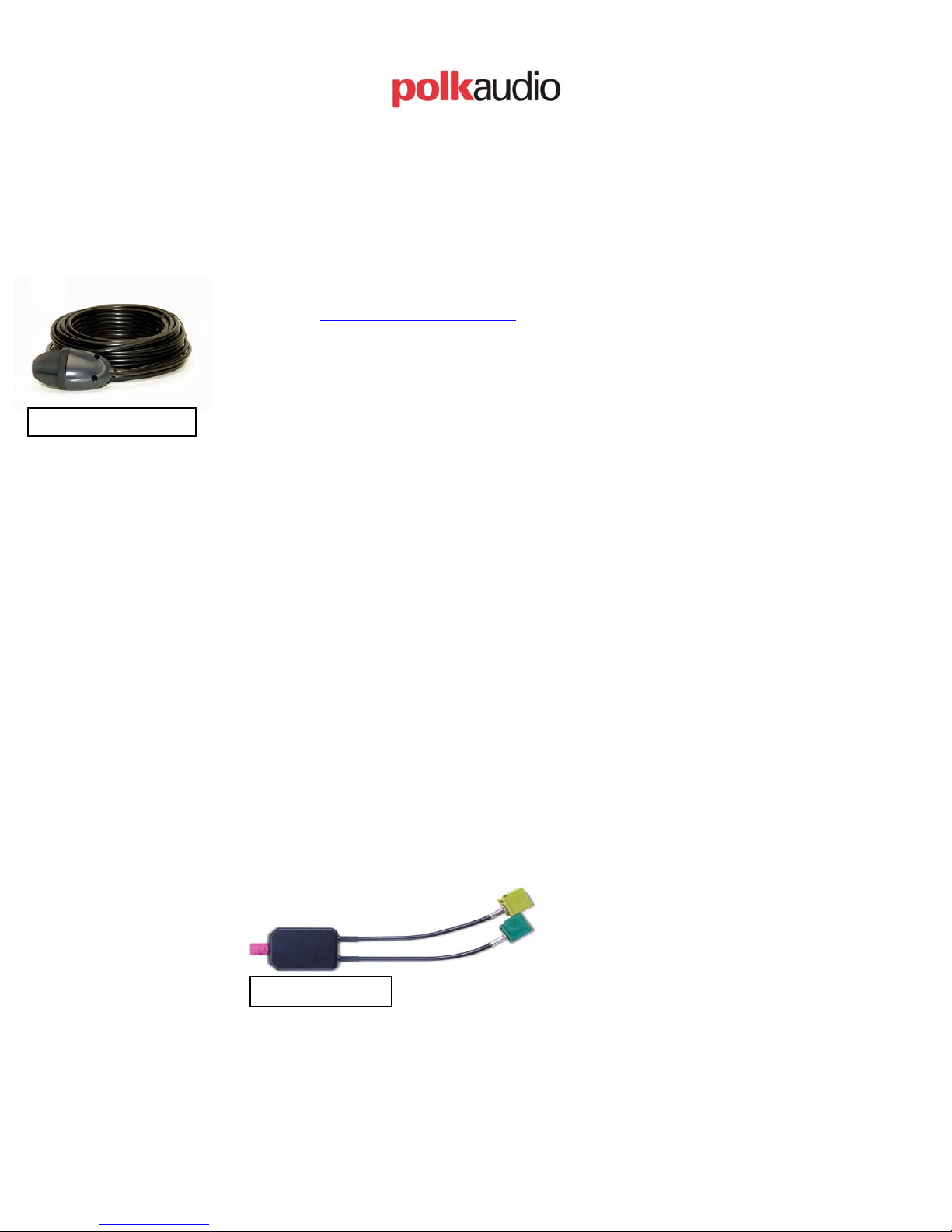
XM-EXT50
to locate the antenna where there is a strong XM signal, please see the
section below on extension Cables.
B. Extension Cable:
Your High-Gain Home Antenna comes with 20-feet of cable. If that is not
sufficient to locate the antenna where there is a strong XM signal, purchase a
50-foot cable extension (Polk Audio recommends the Terk XM-EXT50) from
Polk Audio (http://shop.polkaudio.com
) or your local retailer. Up to two
extensions can be used together for a total of 120-feet of cable.
The Terk XM-EXT50 cable is 50-feet long, weather resistant, and has a built
in signal amplifier to match the input gain with the XRt12 XM Reference
Tuner.
C. Prewire installation:
Prewire installation can be accomplished by using the 50-foot extension cable
(Terk XM-EXT50) to route from the XRt12 Tuner location to the desired
antenna location. The Antenna that comes with your XRt12 tuner has 20-feet
of cable and up to two extension cables can be used for a total antenna cable
length of 120-feet.
For installations that require cables longer than 120-feet, we do not have an
adequate solution at this time. We are working with Terk to develop a
solution in the near future. Please contact us if this is a requirement for your
installation.
D. Antenna Splitters:
With the use of the Terk XM-SP you can connect two XRt12 units to a single
antenna cable.
Terk XM-SP
Polk Audio XRt12 CI Guide Page 3 1/19/05
Revision 3.0
Page 4

II. IR Codes & Remote Controls:
CODES:
The following IR codes are accepted by the Polk Audio XM Reference Tuner XRt12
Code Type: Extended RC5 or RC5x
Key No. Function System
Code (DEC)
Command Code
(DEC)
Mode or Data
(DEC)
1 Power On/Off (toggle) 27 12 00
- Discrete Power On 27 50 00
- Discrete Power Off 27 51 00
2 Select S 27 32 00
3 Category _ 27 49 00
4 XM – Enter 27 35 00
5 Category ` 27 48 00
6 Select T 27 33 00
7 Mute 27 13 00
8 Preset/Direct 27 34 00
9 Jump 27 62 00
10 “ 1 “ 27 01 00
11 “ 2 “ 27 02 00
12 “ 3” 27 03 00
13 “ 4 “ 27 04 00
14 “ 5 “ 27 05 00
15 “ 6 “ 27 06 00
16 “ 7 “ 27 07 00
17 “ 8 “ 27 08 00
18 “ 9 “ 27 09 00
19 Display 27 58 00
20 “ 0 “ 27 00 00
21 Menu 27 53 00
Remote Controls:
The IR codes for the XRt12 are RC5x which includes a toggle bit as part of the code.
As a result, a single press of a key will send out a toggle bit of 0 + the IR code, the
second press of the same button will send out a toggle bit of 1+ the IR code. The
toggle bit may cause some confusion when programming a learning remote control if
the learning remote does not have the capability to learn RC5x codes. If your
learning remote does not accept RC5x codes then the remote will need to be
programmed as follows and the tuner must be running Version 35 or later software:
To teach a non-RC5x compatible remote:
Polk Audio XRt12 CI Guide Page 4 1/19/05
Revision 3.0
Page 5

1) Follow the Learning Remote’s instructions for alignment of the two remote
control IRs.
2) Following the learning remote’s instruction for teaching the learning remote
the XRt12 remotes codes. Usually this consists of:
a) Pressing “Learn” key on learning remote
b) Press key to be taught the new code
c) Press the desired feature key on XRt12 remote
d) If confirm process is requested – go to step 3
3) When a confirm key press is requested – point the XRt12 remote away from
the learning remote and press the desired feature key ONCE. Then, return the
XRt12 remote back to the proper positioning for the learning remote and
continue the confirmation process.
This process basically lets the learning remote learn one code and ignores the
toggle bit. An update (version 35 or later) to the firmware will allow remotes that
can not learn the toggle bit to work with the tuner.
Learning remotes compatible with RC5x codes:
The following learning remotes have been tested and determined to work with the
XRt12:
Manufacture Product
Philips Pronto
TSU3000
Philips Pronto
TSU3000
Home Theater
Master
Home Theater
MX350
MX3000
Master
Harmony
Harmony
676
688
Polk XRt12
Firmware Version
Ver. 34 or 35 (see
comments)
Ver. 35
Ver. 35
Ver. 34 or 35
Ver. 34 or 35
Ver. 34 or 35
Comments
Preprogrammed codes are located on our
website ( www.polkaudio.com)
Does not detect RC5x codes so codes
must be taught by per above.
IR learning works with version 35, but
not 34
works with Delphi SkyFi codes included
in software (both ver 34 and 35)
online database has working codes for
both 34 and 35; does learn RC5x codes
online database has working codes for
both 34 and 35; does learn RC5x codes
As codes become available we will post them on our website for your reference and
use. www.polkaudio.com
Polk Audio XRt12 CI Guide Page 5 1/19/05
Revision 3.0
Page 6

III. 12 Volt Trigger:
The 12V Trigger Input allows your 12V-trigger-capable preamp or receiver to force the
XM Reference Tuner to go from STANDBY mode (power button illuminated, front
panel display off) into ON mode (power button not illuminated, front panel display on) or
vice versa without the need to press the POWER button. To disable the 12V Trigger
Input feature, simply do not connect anything to the 12V Trigger Input jack on the rear
panel of the XM Reference Tuner. To enable this feature, connect a 1/8" mono plug
cable (tip +/ barrel - ) from your preamp or receiver's 12V Trigger Output to your XM
Reference Tuner's 12V Trigger Input jack on the rear panel. So long as the XM Tuner
stays plugged into an active AC outlet, your XM Reference Tuner is ready to respond to
power mode changes sent from your preamp or receiver.
Polk Audio XRt12 CI Guide Page 6 1/19/05
Revision 3.0
Page 7

IV. The ASCII Command Definitions
RS-232 Overview:
The RS-232 port allows communication with the XRt12. All commands that are present
on the front panel or the remote control of the XRt12 are available via the RS-232 port.
In addition, the display data that is shown on the LCD display (or video output) is
available over the RS-232 port. This document defines the ASCII commands, which are
used to control the Polk Audio XRt12.
Settings:
The communication parameters for communicating with the Polk Audio XM Reference
Tuner - XRt12 are:
Cable and connector Pin-Out:
DB9 female-to-female 1:1 cable
Pin 1 - Floating
Pin 2 - Transmit
Pin 3 - Receive
Pin 4 - Floating
Pin 5 - Ground
Pin 6 - Not connected
Pin 7 - Not connected
Pin 8 - Not connected
Pin 9 - Not connected
Parameter Setting
Bits per Second 9600
Data Bits 8
Parity None
Stop Bit 1
Flow Control None
Polk Audio XRt12 CI Guide Page 7 1/19/05
Revision 3.0
Page 8

ASCII command definitions:
All of the commands are case sensitive and end by the “return” key.
Command Parameter
ConnectXRt12 /
DisconnectXRt12 /
ChannelSelect Channel number
PresetSelect Preset number
GetSongInformation /
GetChannelInformation /
GetHardwareId /
GetAntennaStrength /
Mute /
Unmute /
ChangeDisplay /
Jump /
Menu /
CategoryRight Number
CategoryLeft Number
SelectUp Number
SelectDown Number
Enter /
Description
Connects the controller to the XRt12
Disconnects the controller from the XRt12
Selects the channel. The number is always
three-digits (max. 255): ex.
ChannelSelect 052
Selects the memory preset. The number is
always two-digits (max. 20): ex.
PresetSelect 06
Retrieves the current channel’s artist name
and song title (length =16 bit max each for
name & title, ASCII)
Retrieves the current category name,
channel number, and channel name (length
=16 bit max, ASCII)
Retrieves the unit hardware ID
Retrieves the signal quality
Mutes the audio output
Reactivates the audio output
Changes the display mode between full
artist and song information, channel-only
information, and scrolling artist and song
information
Switches between current channel and
previous channel
Activates the settings menu
Changes categories forwards. The 2-digit
number is how many times the command
is repeated (max. 20): ex.
CategoryRight 08
Changes categories backwards. The 2digit number is how many times the
command is repeated (max. 20): ex.
CategoryLeft 03
Changes menu or channel selection up.
The 2-digit number is how many times the
command is repeated (max. 20): ex.
SelectUp 12
Changes menu or channel selection down.
The 2-digit number is how many times the
command is repeated (max. 20): ex.
SelectDown 03
Sets the menu selection
*Note – All OSD menu functions have a 10-second timeout period.
System
Response
None
None
None
None
Yes – see
example
Yes – see
example
Yes – see
example
None
None
None
None
None
None
None
None
None
None
Polk Audio XRt12 CI Guide Page 8 1/19/05
Revision 3.0
Page 9

Examples of System Response:
System response for the 'Get' commands are as follows:
GetSongInformation (return command)
Current Channel Artist Name:
B.B. King (1 blank space + 16 characters + return command)
Current Channel Song Title:
Take It Home (1 blank space + 16 characters + return command)
GetChannelInformation (return command)
Current Channel Number is: 74 (2 blank spaces + 3 characters + return command)
Current Channel Name is:
Bluesville (16 characters + return command)
Current Category Name is:
Jazz & Blues (16 characters + return command)
GetHardwareId (return command)
The RADIO ID is:
XYZPDQ11 (8 characters + return command)
GetAntennaStrength (return command)
Current Signal Quality is:
Good Signal (This response represents 3 antenna bars)
Marginal Signal (This response represents 2 antenna bars)
Weak Signal (This response represents 1 antenna bar)
No Signal (This response represents 0 antenna bars)
When an unrecognizable command is entered, the system will respond with:
Invalid Command (+ return command)
When an unrecognizable parameter is entered, the system will respond with:
Invalid Parameter (+ return command)
Polk Audio XRt12 CI Guide Page 9 1/19/05
Revision 3.0
Page 10

V. Firmware updates:
Firmware updates are available to handle the IR coding issues. These updates may be
installed over the RS-232 port using the following equipment:
Hardware:
• A Windows 9x/NT/2000/XP PC with a DB9 COM port
• A DB9 female-to-female 1:1 cable
• The Polk Audio XRt12 XM Reference Tuner + Remote Control
Software:
• You need to download the free software (AVR Studio 4.10, build 356 or later)
from the ATMEL website.
http://www.atmel.com/dyn/products/tools_card.asp?family_id=607&family_
name=AVR+8%2DBit+RISC+&tool_id=2725
• the Polk Audio system files
For complete instructions on the upgrade process; please contact Polk Audio
Customer Service at (800) 377-7655 (polk).
Polk Audio XRt12 CI Guide Page 10 1/19/05
Revision 3.0
 Loading...