

Polk Audio VANISHING 620-RT, VANISHING 80F/X -LS, Vanishing 80F/X-RT Instructions Manual

LS Model
80f/x®-ls
RT Models
80f/x®-rt
620-rt
ENGLISH
IMPORTANT SAFETY INSTRUCTIONS
READ BEFORE OPERATING EQUIPMENT
1. Read these instructions.
2. Keep these instructions.
3. Heed all warnings.
4. Follow all instructions.
5. Do not use this apparatus near water.
6. Clean only with dry cloth.
7. Do not block any ventilation openings.
Install in accordance with the
manufacturer’s instructions.
8. Do not install near any heat sources
such as radiators, heat registers, stoves,
or other apparatus (including amplifiers)
that produce heat.
9. Refer all servicing to qualified service
personnel. Servicing is required when the
apparatus has been damaged in any way,
liquid has been spilled or objects have fallen
into the apparatus, the apparatus has been
exposed to rain or moisture, does not operate
normally, or has been dropped.
10. WARNING: To reduce the risk of fire or
electric shock, this apparatus should not be
exposed to rain or moisture and objects filled
with liquids, such as vases, should not be
placed on this apparatus.
Product Disposal—Certain international, national and/or local laws and/
or regulations may apply regarding the
disposal of this product. For further
detailed information, please contact
the retailer where you purchased this
product or the Polk Audio Importer/
Distributor in your country. A listing of Polk Audio
Importer/Distributors can be found on the Polk Audio
website www.polkaudio.com or by contacting
Polk Audio at 5601 Metro Drive, Baltimore,
Maryland 21215, USA—Phone: +1 410 358-3600.
WARNING: Listen Carefully
Polk Audio loudspeakers and subwoofers are
capable of playing at extremely high volume levels,
which could cause serious or permanent hearing
damage. Polk Audio, Inc. accepts no liability for
hearing loss, bodily injury or property damage
resulting from the misuse of its products.
Keep these guidelines in mind and always use
your own good judgment when controlling volume:
• Youshouldlimitprolongedexposureto
volumes that exceed 85 decibels(dB).
TAKE INVENTORY
Inside each speaker container, you should
find the following:
1. One in-ceiling loudspeaker or one set
of loudspeakers for F/X
®
models only.
2. Speaker cutout mounting template
3. One Sheer-Grille (for each speaker)
4. One Owner’s Manual
5. Registration Card
Important Note: If anything is missing or
damaged, or if your speaker fails to operate,
notify Polk Audio Customer Support Services
immediately at 800-377-7655.
INSTALLATION RECOMMENDATION
FOR OPTIMUM PERFORMANCE
Important Note: Vanishing Series Loudspeakers
are not magnetically shielded and should not be
placed closer than 1' (30cm) from a CRT (tube)
television or video monitor.
Important Note:Youshouldhaveathorough
understanding of and adhere to all local building
and fire codes. Also, you should be familiar with
the area behind the wall or ceiling into which
you plan to install your speakers. Always use
wire that meets appropriate building and fire
codes. (Note: Wiring is best performed
by an experienced professional.)
When installing your loudspeakers, be aware of
the weight of your particular model and the sturdiness of the material into which you are installing
the speaker. Be aware of any concealed studs,
electrical wiring or plumbing in the wall or ceiling
into which you are installing the speakers.
If you doubt that you possess the necessary
skills or tools, consult your Polk Audio dealer
or a professional installer.
WIRE RECOMMENDATIONS
(minimum recommended)
Runs Gauge
Lengths up to 25' 18 or 16
Lengths greater than 25' 16 or 14
but less than 50'
Lengths greater than 50' 14 or 12
but less than 75'
Lengths greater than 75' 12
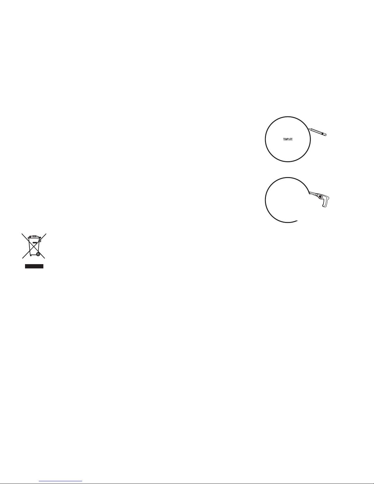
LOUDSPEAKER INSTALLATION
You will need:
• Pencilformarkingthelocationofinstallation.
• Keyholesaw,utilityknifeormaterial-
appropriate tool for cutting drywall
or other wall material.
• Screwdriver,preferablypowered,
with Phillips Head bit.
• Powerdrillwithappropriatebit
(optional, for starting wall cut).
Trace around the template.
Cut the hole with the appropriate tool.
IMPORTANT INFORMATION BEFORE
YOU INSTALL YOUR LOUDSPEAKERS
Wall Or Ceiling Surface Preparation
If you’re installing your Vanishing Series speaker
into a heavily textured wall or ceiling (e.g. stucco
or popcorn finish), you must prepare the wall
surface immediately around the speaker
cutout. Sanding and smoothing the wall or
ceiling surface will ensure the speaker and
grille both seat properly and flat to the surface.
For more about safe volume levels, go to the
Occupational Health and Safety Administration
(OSHA) guidelines at http://www.osha.gov/dts/
osta/otm/noise/standards_more.html
2 Polk Audio Customer Service: 1-800-377-7655 (Outside US & Canada: 410-358-3600) Monday-Friday, 9:00 AM-5:30 PM EST, polkcs@polkaudio.com
IMPORTANT INFORMATION SHOULD
YOU CHOOSE TO PAINT YOUR GRILLES
Because of its ultra-thin profile, the Vanishing
Series Sheer-Grille
™
requires a specific painting
procedure to ensure smooth, even coverage.
The grille scrim and perforated grille come
assembled and require no disassembly.
Paint Recommendation
We highly recommend you use a can of spray
paint matched to the ceiling color you want the
Sheer-Grilles to blend with.
Important Note: Never use a brush or roller to
paint the grilles, as this will clog the perf holes.
To paint the Sheer-Grille
1. Elevate the Sheer-Grille off of a flat surface.
This will ensure even coverage of the grille
frame and make it easier to pick up.
Mounting Idea: A single spray can cap
will raise the grille high enough.
2. Hold the spray paint about 12" from
the grille and at a 45° angle.
3. Apply one light, thin coat, moving evenly
side to side over the grille, then work your
way around the perimeter of the grille
to ensure you cover the grille frame.
4. After each application of paint, wait
approximately 1 minute, rotate the
grille 90°, and apply the next thin coat.
Important Note:Youmustrotatethegrille
90°. Use your hands to define the next 90°
rotation and always rotate the grille in the
same direction of travel.
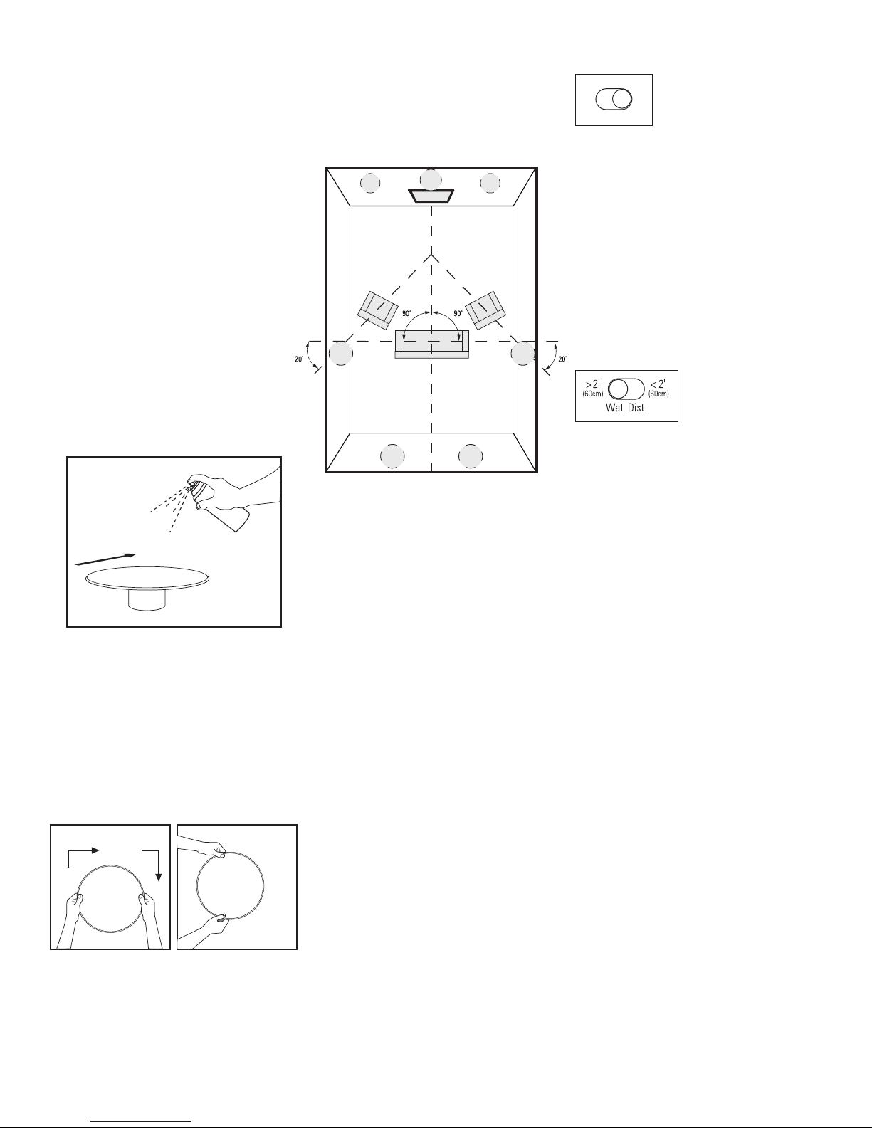
SURROUND SPEAKER PLACEMENT
Polk Audio F/X
®
surround loudspeakers give you
nearly endless placement options. But remember
that where you place your surround speakers
requires some careful thought, as installation
requires that you cut a hole in your wall or ceiling.
TV
Diagram shows speaker locations for
5.1 and 7.1 systems, when two additional
in-ceiling speakers are installed at back
of the room.
Left/Right Orientation: F/X
®
surround loudspeakers have a left/right orientation, and each
speaker is clearly marked on the serial number
label on the back of the magnet for installation
on either the right or left. Right and left are
defined from your listening area as you face
your system’s center channel.
Please Note: For more on speaker placement go
to: www.polkaudio.com/education/article.php?id=15
or www.polkaudio.com/downloads/hthandbook.pdf
ROOM ENVIRONMENT CONTROLS
Solid / Diffuse
Imaging
Imaging (80
f/x-ls only)
F/X Surround Loudspeakers offer switchable
“Diffuse” and “Solid” imaging patterns
to create the surround effect you desire.
A “Diffuse” image is defined as one which
creates a “cloud” of sound; think of the effect
as ambient sounds which fill the environment
all around you, but are less localizable.
A “Solid” image is one which creates a more pinpoint sound; sound is more localized. The location
of sounds in the sound field is more identifiable.
Wall Distance Switch (F/X models only)
In-ceiling loudspeakers excel when placed
more than 2' (60cm) from side walls. If position
limitations demand that in-ceiling loudspeakers
be installed closer than 2' (60cm) from side walls,
the proximity of the surface can result in a response
“bump” between 50 and 200Hz. This can cause
in-ceiling speakers to sound “boomy.” The
“Wall Distance” switch flattens response
and eliminates “boominess” without sacrificing
deep bass response, for more lifelike sound.
5. Three light, even applications should cover
the grille and frame adequately. Remember
to work your way around the grille frame
to cover it evenly and completely.
For more information visit our website at www.polkaudio.com 3
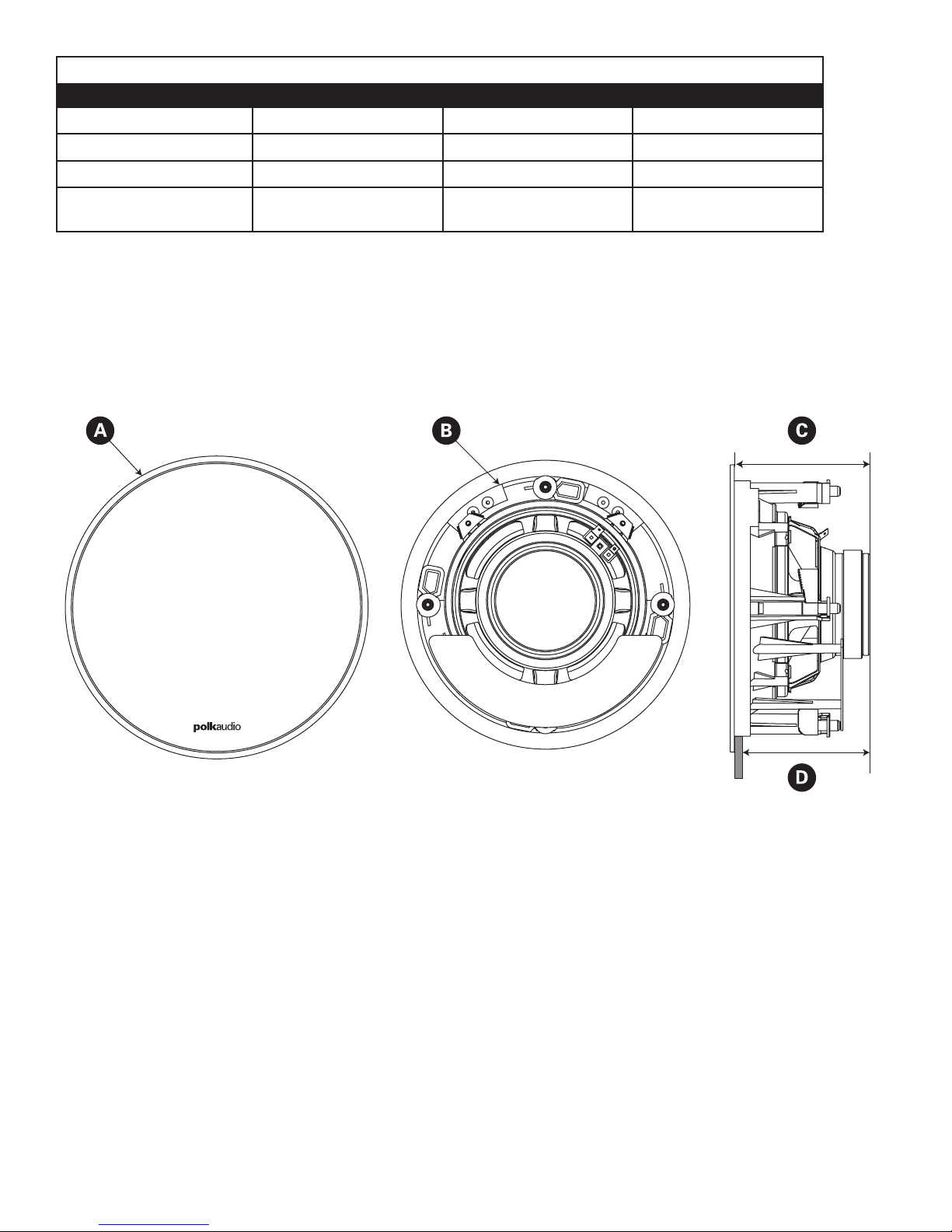
DIMENSIONS
Model 80f/x-ls 80f/x-rt 620-rt
A. Overall Dimensions
B. Cutout Dimensions
C. Product Depth
D. Mounting Depth
(using 1/2" drywall)
11 1/8" (282.6mm) 11 1/8" (282.6mm) 9 5/8" (244.5mm)
9 3/8" (238.1mm) 9 3/8" (238.1mm) 8 3/16" (208mm)
5 3/16" (131.8mm) 5 1/16" (128.6mm) 4 1/4" (108mm)
4 11/16" (119.1mm) 4 9/16" (115.9mm) 3 3/4" (95.3mm)
SPECIFIATIONS
For complete Vanishing Series specifications, visit www.polkaudio.com
4 Polk Audio Customer Service: 1-800-377-7655 (Outside US & Canada: 410-358-3600) Monday-Friday, 9:00 AM-5:30 PM EST, polkcs@polkaudio.com
Drywall
 Loading...