


Microwave barrier
for perimeter protection
at long range.
Installation manual

POLITEC S.r.l. | Manual MANA MW – Ver. 2.2.2
2
INDEX
1
COMPONENTI PRINCIPALI
Pag. 3
2
ASSEMBLAGGIO POZZETTO
Pag. 5
POSIZIONAMENTO POZZETTO
Pag. 6
3
ALLINEAMENTO COLONNE
Pag. 6
WALL MOUNTING
Pag. 6
POLE MOUNTING
Pag. 6
4
CONNECTIONS AND DESCTIPRIONS
Pag. 7
CABLE AND WIRING
Pag. 7
TRASMITTER/RECEIVER
Pag. 8
5
FREQUENCY SELECTION
Pag. 9
6
ALLIGNMENT TEST
Pag. 9
7
SETTING TIME
Pag. 11
TIME CHOICE
Pag. 11
8
ENVIRONMENTAL DISQUALIFICATION
Pag. 13
9
ADDITIONAL TAMPER
Pag. 13
10
TECHNICAL FEATURES
Pag. 14

POLITEC S.r.l. | Manual MANA MW – Ver. 2.2.2
3
PRINCIPAL COMPINENT
N.
Parts
Quantity
Description
1
1
Top Cap
2
1
Aluminium Profile
3
2
Aluminium inserts
4
1
IR cover
5
1
Parable Mana
6
1
Illuminator Mana
7
1
Cavity Tx or Rx
8
2
Handling system
9
1
Plate
10
1
Tx or Rx board
11
1
Power board
1
8
6
7
5
4 2 3
9
10
11

POLITEC S.r.l. | Manual MANA MW – Ver. 2.2.2
4
1. ASSEMBLING THE CABLEPIT
1. Insert the highlighted edge into other section and fix with screws
2. Insert the third section in the same way and fix with screws.

POLITEC S.r.l. | Manual MANA MW – Ver. 2.2.2
5
3. Enlarge the two opposite walls of cable pit to allow the positioning of last section.
4. Insert and well fix the missing screws.

POLITEC S.r.l. | Manual MANA MW – Ver. 2.2.2
6
1.1. CABLE PIT POSITIONING
The placement of the cable pit for MANA columns, after assembling, have to be done in the following way:
cement all around the cable pit keeping the top edge of it at same level of ground.
POSSIBLE CORRECTION OF THE INCORRECT POSITIONING
Placement should be perpendicular to the ground. If the base is not in perfectly at ground level, is possible to
adjust it through the insert regulation of cable pit.
On the side that must be corrected loosen the insert in order to get the right inclination.
CORRECT POSITIONING
BY ADJUSTING INSERTS
EXAMPLE
OF SETTING
WRONG POSITIONING

POLITEC S.r.l. | Manual MANA MW – Ver. 2.2.2
7
1.1. Installations Problems:
Number of sections
Having to design protection with volumetric barriers of a closed perimeter within a certain number of
sections that take into account the management need of the entire plant, it must be remembered that it is
always preferable to install an even number of sections. This consideration is bound to the fact that the
likely reciprocal interferences between adjacent sections are annulled should at the vertices of the
polygon (cross), resulting from the installation of the various sections, be installed two equipment with
the same name, two transmitters or two receivers. It is evident that this might occur only if the number
of sections is even.Should it not be possible to have an even number of sections then some careful
considerations must be made on interferences that might likely occur in order to find the vertex point
where retained best to place the transmitter near the receiver. The following pictures show some typical
cases for which the most correct solution is given.

POLITEC S.r.l. | Manual MANA MW – Ver. 2.2.2
8
Particolar conditions
1. Ground conditions: It is inadvisable to install the equipment along sections with tall grass
(more that 10cm), ponds, longitudinal waterways, and all those types of grounds whose structure
is rapidly mutable.
2. Obstacles: the fences, are generally metallic therefore highly reflecting hence causing various
problems, for this reasons some precautions are suggested:
First of all, make sure that fence has been properly fixed in order that the wind does not
move.
If it is possible the microwave beam shouldn’t be placed in parallel to a metallic fence, is
necessary to create a corner with it
Metal fences placed behind the equipment night cause distorsions to the sensitive beam
especially, and might cause movement detection in unexpected spots, with subsequent
likely generation of false alarms.
In case of Mw barrier should be installed in a corridor between two metallic fences, the
width of the corridor should be necessary not less to 5m.
Along the section, within the area of the protectiion field, are allowed pipes, poles or similiar as long as
their dimensions, with respect to the protection beam, are not too excessive. The trees, hedges, bushes in
general, need very great attention if near or within the protection sections.

POLITEC S.r.l. | Manual MANA MW – Ver. 2.2.2
9
1.1. Connections and circuit descriptions TX
1
POWER SUPPLY
The power connector is linked to power supplier via a flat cable.
2
MW CONNECTOR
The connectors "MW" or Output 1 / 2 are used to connect the cavity
transmission. Normally uses the output "Output 1", and only in case of
double barrier microwave using the synchronized output "Output 2".
3
LED
The "Led insert jumpers", inserted in position 2-3, enables the power of
Led Output "and" Led VDC ", indicating the presence of their tensions.
Return after the test at rest 1-2. NB The "Output LED" has a lower
light intensity of Led VDC, when the cavity "TX" is inserted.
4
DIP SWITCH
The "channel selector" allows you to select the desired channel by
switching to "ON".
NB The selected channel must be the same as that of the Circuit "Rx”.
1
4
3
2

POLITEC S.r.l. | Manual MANA MW – Ver. 2.2.2
10
1.1. Connections TX
TO CAVITY TX
24.5 GHz
CONTACT
TAMPER NC
POWER INFRARED
BARRIER
BATTERY 12V
TO OTHER
HEATERS
LAND 230V~ LAND
TRANSFORMER
TX

POLITEC S.r.l. | Manual MANA MW – Ver. 2.2.2
11
Connections and circuit descriptions RX
1
Input Connector Mw
connect the receiver cavity
2
OUTPUT
CONNECTOR
1
NC alarm contact
2
3
Tamper contact
4
3
POWER SUPPLY
Piacere The power connector is connected to power via a flat cable.
4
DIP SWITCH 1
allows you to check the voltage supply, the value of sensitivity, goodness of
the signal, the walk test and the test alignment (see table previous page).
Permette di verificare le tensioni di alimentazione, il valore di sensibilità, la
bontà del segnale, il walk test e il test di allineamento
5
DIP SWITCH 2
choose the desired channel by switching to"ON". NB The selected
channel must be the same as that of the Circuit "Tx".cosi
6
LED CHANNEL
indicates that the channel is tuned with the transmitter.
7
LED ALARM
indicates that the system is not in alarm (when there is the alarm LED goes
off).
8
LED ALIGNMENT
Red: weak signal
5
1
3
4
11
9
7 6 8
10
10
2

POLITEC S.r.l. | Manual MANA MW – Ver. 2.2.2
12
Yellow: signal fair
Verde: segnale forte
9
Voltmeter
indicates the voltage in volts of the selected function (see table previous
page).
10
Trimmer
(Guadagno, Walk Test, Sensibilità, Ritardo), regolazioni da effettuare durante
l’installazione
11
Buzzer
is activated with the "Walk Test" (selector functions):
Continuous beep = Alarm
Sound intermittently variable = Tell sensitive area
Configurazione DIP SWITCH
1
LEDS
Insert LED bar for Test Alignment
2
FIELD
Display on LED bar signal Rx strength
3
OPEN
Disconnect CAG (automatic gain control)
4
WALK
Walk Test (skill the "Buzzer")
5
CAG
View the gain value (optimum 4.5-6.5)
6
SENS
Display Value Sensitivity (0 to 9)
7
5V
Display 0.2 ± 5V supply
8
9V
Display 0.2 ± 9V supply
9
13V
Display 13.8 ± 0.3 supply
10
VOLT
Input Voltmeter (to display items 5 ÷ 9)

POLITEC S.r.l. | Manual MANA MW – Ver. 2.2.2
13
1.1. Connections RX
TO CAVITY TX
24.5 GHz
POWER INFRARED
BARRIER
CONTACT
TAMPER NC
CONTACT
ALARM NC
POWER
SUPPLIER
TO OTHER
HEATERS
BATTERY 12V
LAND 230V~ LAND
TRANSFORMER
TO CAVITY TX
24.5 GHz
POLITEC S.r.l. | Manual MANA MW – Ver. 2.2.2
14
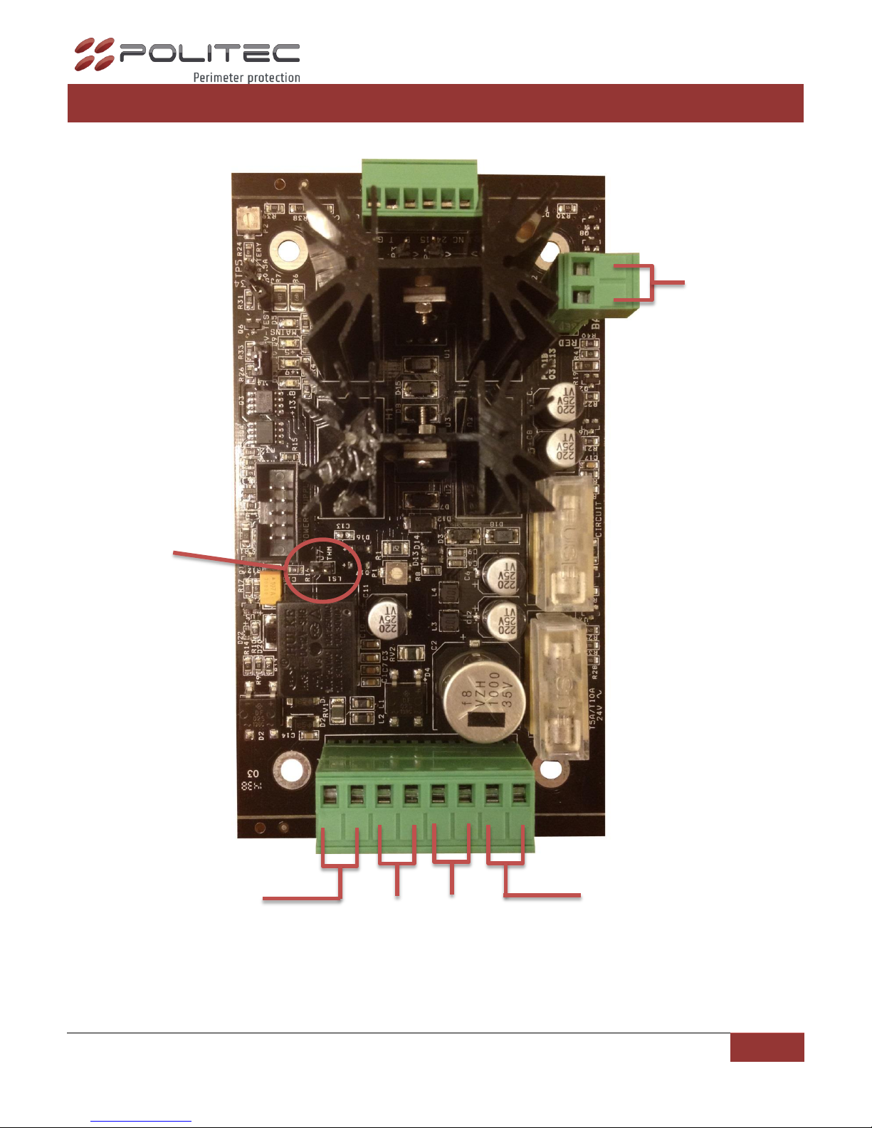
CONNECTIONS AND DESCRIPTIONS PS01B
IN
~19V
OUT
~24V
IN
~24V
OUT
13.8V
BATTERY
1 2 3 4 5 6
J7

POLITEC S.r.l. | Manual MANA MW – Ver. 2.2.2
15
"Power Connector Circuit Tx or Rx" is to be connected with flat cable to the power connector
board Tx or Rx.
"Jumper V-Test" inserted in position 1-2 enables the lighting of LED power supply, 5V 9V 13.8V.
Return after the test at rest position 2-3.
The 4th Led called "Mains" is always seen when the board is powered by the transformer while it
is off if the battery involved.
"Jumper 0.5 A battery". Insert jumper when using more than 5 Ah batteries.
NB Current limit for battery charging 0.5 A. Without the current bridge load limit is 0.25 A.
" Heater Fuse " normally installed 5 A delayed protecting heaters circuits.
" Circuits Fuse " normally installed by 0.8 A slow, protecting Tx or Rx and infrared circuits.
N
SIGLA
DESCRIZIONE
1
GND
Negativo alimentazione.
2
T
Test batteria. Applicando 5 V è possibile verificare che la batteria abbia una tensione
di uscita >11.4Vdc. Tale informazione viene data sul morsetto “B”.
3
B
Uscita ad alta impedenza se la tensione fornita dalla batteria è <11.4Vdc.
Uscita 120Ω se la tensione della batteria è >11.4Vdc.
Tale informazione è valida se “T” è attivo.
4
15
Uscita ad alta impedenza se la tensione fornita dall’alimentatore è <12.4Vdc.
Uscita 120Ω se la tensione fornita dall’alimentatore è >12.4Vdc.
5
24
Uscita ad alta impedenza se la tensione fornita dal trasformatore sui morsetti
“24Vin” è <18Vac.
Uscita 120Ω se la tensione fornita dal trasformatore sui morsetti “24Vin” è >18Vac.
6
NC
Non collegato
CONNECTIONS AND DESCRIPTIONS CAVITY TX AND
RX
The switch located on the cavity Tx and Rx is positioned to OFF only after installation and after giving
voltage to the columns. The ON position, the active protection of the "receiver" cavity by electrostatic
discharge and damage resulting from installation.

POLITEC S.r.l. | Manual MANA MW – Ver. 2.2.2
16
CONNECTIONS NOTE
Connection to the mains:
Columns can be powered by 19V AC to 13.8V DC, but is preferable by the last.
Connection:
The connection between the transformer and the 230 V ~ must be made with cables whose section
is approximately 1.5 mm ². It is strongly recommended to use an upstream fuse 1 A delayed. The
cable that carries power from the transformer to MANA will be as short as possible, should come
with shield grounded. The two wires must be connected to terminals 1-2 of the "power
connector”. The transformer used must have the following characteristics:
Primary voltage = 230 V~
Secondary voltage = 18 o 19 V~ 1 A
Secondary voltage = 24 V~ 6 A
Minimum power = 160 VA
NB: Use only safety transformers with a certificate, such as 60950. Must be given good
grounding of the housing processor. Connecting the transformer to 230 V ~ must be made
through a device that has the following characteristics:
1. Bipolar with minimum distance between the contacts of 3mm
2. Provided in the fixed installation
3. Easily accessible
In any case, you should carefully follow the requirements contained in the related law of
fixed devices permanently connected to the mains as the Law 46/90 and CEI 64-8.
In the case of mains very disturbed to add an effective filter 230V 1 A
Connection to the Emergency supplier:
Within each column is provided space to house a rechargeable Lead 12 V - 1.9 Ah. The internal
battery is normally recharged from food through a current limiter.
NB: The casings of the battery used, shall have a flammability class HB or better (UL 94)

POLITEC S.r.l. | Manual MANA MW – Ver. 2.2.2
17
Connection to the central
Connections to the central processing must be made through shielded cables.
C / o contact Alarm:
The outputs of the devices consist of relay contacts normally closed for reporting states and
tampering alarm.
The contact output to alarm consists of a static relay with a range from 12V 1A.
Tamper output contact is given by the microswitch, with scope 100mA max.
The outputs are enabled for the following reasons:
Alarm Output
1. Intruder alarm on Rx
2. Alarm Channel on Rx
Tamper Output
1. Opening the cap of barriers
NB The High Risk Protection is essential that the detectors are tested with adequate
intervals to Test Operational. In this way the control unit will be able to detect attempts to
circumvent.

POLITEC S.r.l. | Manual MANA MW – Ver. 2.2.2
18
SENSITIVE ZONE
The sensitive area depends on the distance Tx Rx, the sensitivity and the type of antenna. The diagram
below illustrates the sensitive area of diameter at half length as a function of total distance and
sensitivity.
L’altezza consigliata per installazioni di tipo classico è di circa 70 cm dal centro dell’antenna al suolo, con la
sensibilità media impostata.
NB: remember to adjust the sensitivity of "MANA" according to
half width of the beams is desired. As the threshold is higher, the lower the sensitivity and
vice versa.
0 50 100 150 200 250 300
0
2
4
6
8
10
12
Diameter in the
middle (m)
Maximum sensitivity
Length is in meters
L
D
X
X X X
Minimum sensitivity

POLITEC S.r.l. | Manual MANA MW – Ver. 2.2.2
19
DEAD ZONE
The length of dead zones in the vicinity of the columns is on the same apparatus is the distance from the
ground, the sensitivity is set to the Rx circuit. The recommended height for installation of a conventional
type is approximately 70 cm from the center of the antenna to the ground, with the sensitivity set to medium.
0 2 4 6 8 10 12 14 16 18 20
0
10
20
30
40
50
60
70
80
90
H equipment
ground (cm)
Length of the dead
zone in meters
Maximum
sensitivity
Minimum
sensitivity

POLITEC S.r.l. | Manual MANA MW – Ver. 2.2.2
20
OPERATION MODE
COLUMN TRANSMITTER
After you remove the cover and shield, make connections to the mains power transformer and tamper
circuit.
1. Check the various connections: the power transformer to the circuit, the battery, the power
circuit to circuit and transmitter cavities TX (See pp. 9, 12-13).
2. Power board, check the LED lights on Mains power adapter and three power LEDs with V-Test
jumper inserted in position 1-2 (see pp. 12-13).
3. Turn OFF the switch which is on cavity TX. (See page 14).
4. Verify that is in position ON one of the four switches of the "channel selector" tab, TX (same as
RX) See page. 9.
5. Insert the jumper in position 2-3 to verify that LEDs output and VCC (see page 10).
6. Replace the two jumpers in the resting position.
COLUMN RECEIVER
After you remove the cover and shield, make connections to the mains power transformer and tamper
circuit.
1. Check the various connections: the power transformer to the circuit, the battery, the power
circuit to circuit and transmitter cavities RX (Vedi pagg. 10-13).
2. Power board, check the LED lights on Mains power adapter and three power LEDs with V-Test
jumper inserted in position 1-2 (Vedi pagg. 12-13).
3. Turn OFF the switch which is on cavity RX.(Vedi Pag.14).
4. Verify that is in position ON one of the four switches of the "channel selector" tab(same as TX)
(Vedi pagg. 10-11).
5. Check the "voltages" on the receiver, turning in ON position the switch N.10 "selector function",
and displaying the desired tension (5, 9, 13.8 volts) with dip No 7-8-9 (See pp. 11-12).
Perform an initial visual alignment between the two columns (TX and RX).
Horizontal orientation: Loosen the screws and turn the column.
Vertical orientation: Loosen the screws of the handling system of the parable, and rotate.
Verify that on the board RX the leds alarm and Channel are on. Otherwise proceed with the electronic
alignment, however, be made to obtain a precise alignment.

POLITEC S.r.l. | Manual MANA MW – Ver. 2.2.2
21
ALIGNMENT
Turn ON the dip of the "Selector Function" numbers 1,2 and 3, leaving all others to OFF.
Align horizontally and vertically then the parable of the receiver for maximum signal seen on
"Led test alignment”.
If the signal is too strong or too weak to act on the knob of the "gain" so that only the first four
LEDs light up red.
Rerun the orientation of the parabola RX. Once the maximum orientate the parable TX.
Goodness signal: Turn OFF the switching of the "selector functions" 1 and 2 and ON the numbers
3,5 and 10 for the Voltmeter display the gain value. The optimal values are between 4.5 and 6.5
volts.
AGC: position ON the switches numbers 1 and 2 of the "Selector Function", leaving all others to
OFF. Check after about a minute that the 4 LEDs are lit red and 2 yellow LEDs for "Led test
alignment”,too.
Verify that on the board RX the leds alarm and Channel are on. Otherwise proceed with the
electronic alignment.
WALK TEST
1. Turn the knobs "sensitivity" and "Delay" to the minimum and reposition to ¼ of winder.
2. Turn ON the microswitch of the "selector function" Number 4 leaving all others to OFF. This
operation is inserted to signal the buzzer will sound continuously when there is an alarm (see pp.
11, 12), while with a variable sound intermittently when in a sensitive area.
3. In the absence of disturbance signal, turn the potentiometer Walk Test to the point where you
hear no sound.
4. Approaching the center of the cone of the sensitive area, the buzzer there evidence of an
intermittent sound. The sensitive area is represented by the graph on page 17.
5. Test of the acrossing, making sure the intermittent sound of the buzzer and then the long beep
and shutdown "LED Alarm" column on the Rx.
BUZZER: NESSUN SEGNALE

POLITEC S.r.l. | Manual MANA MW – Ver. 2.2.2
22
SENSIBILITY
The sensitivity adjustment potentiometer (see page. 11, 12) affects the alert threshold, the "sensitive
area" (see p.17) and "dead zone" (see p. 18).
NB sensitivity too high can cause false alarms, conversely a too low can prevent the detection of the small
intruders.
Turn ON the dips of the "selector function" Numbers 6 and 10, leaving all others to OFF. In this manner
is displayed on the Voltmeter sensitivity value.
Note that small values indicate a higher value of sensitivity:
0V=maximum sensitivity
9V=minimum sensitivity
Calibration is performed taking into account the user requirements.
Example: the system should not go into alarm when it is crossed by an animal of a certain size. Keep in
mind that high sensitivity can generate false alarms.
BUZZER: SEGNALE INTERMITTENTE
BUZZER: SEGNALE FISSO

POLITEC S.r.l. | Manual MANA MW – Ver. 2.2.2
23
DELAY
The potentiometer adjustment of the delay (see page. 11, 12) affect the crossing speed. To verify the delay
is necessary to experiment crossing at reduced speed. Remember that setting too high or low could cause
false alarms

POLITEC S.r.l. | Manual MANA MW – Ver. 2.2.2
24
TECHNICAL SPECIFICATION
“MW” FREQUENCE
24 Ghz in K band
MAX RANGE
250 m
POWER SUPPLY
220V
ABSORPTION FOR PAIR
Max at 230V 158Watt
OPERATING
TEMPERATURE
- 25°C / + 65°C (Available KIT heaters for lower temperature
operation up to -50°)
“MW” CHANNEL
4 Exchengeable
MODULATION
ON-OFF
SENSIBILITY
ADJUSTMENT
Trimmer.
DELAY ADJUSTMENT
Trimmer.
DIMENSIONS:
Height from 100 to
300 cm
Width 25 cm
Deepness 20 cm
WEIGHT
From 10 to 20 kg for barrier
ALIGNMENT
Eletronic with instruments on motherboard
OUTPUTS
Alarm relay and Tamper
ASSISTENZA TECNICA: +39 039 9081616
 Loading...