

Polini X1R, X2R, X3R User Manual

Page 1
I
I
I
I
I
I
I
V
V
V
I
V
I
I
I. OPERATING INSTRUCTIONS
page
1. Intended use & cautions . . . . . . . . . . . . . . . . . . . . . . . . . . . . . . . . . . . . . . . . . . . . . . . . . . . . . . . . . . . . . . . . . . . . . . 3
2. Initial assembly . . . . . . . . . . . . . . . . . . . . . . . . . . . . . . . . . . . . . . . . . . . . . . . . . . . . . . . . . . . . . . . . . . . . . . . . . . . . . 3
3. Pre-ride checks & initial startup . . . . . . . . . . . . . . . . . . . . . . . . . . . . . . . . . . . . . . . . . . . . . . . . . . . . . . . . . . . . . . . . 5
4. Basic operation & control functions . . . . . . . . . . . . . . . . . . . . . . . . . . . . . . . . . . . . . . . . . . . . . . . . . . . . . . . . . . . . . 5
engine starting & stopping, engine break-in . . . . . . . . . . . . . . . . . . . . . . . . . . . . . . . . . . . . . . . . . . . . . . . . . . . . . . . 5
5. Control adjustment . . . . . . . . . . . . . . . . . . . . . . . . . . . . . . . . . . . . . . . . . . . . . . . . . . . . . . . . . . . . . . . . . . . . . . . . . . 6
brake lever, brake pedal, throttle, bar & lever positioning . . . . . . . . . . . . . . . . . . . . . . . . . . . . . . . . . . . . . . . . . . . . 6
II. GENERAL INFORMATION & SPECIFICATIONS
1. Description - diagram of motorcycle components & controls . . . . . . . . . . . . . . . . . . . . . . . . . . . . . . . . . . . . . . . . . . . 6
2. Specifications . . . . . . . . . . . . . . . . . . . . . . . . . . . . . . . . . . . . . . . . . . . . . . . . . . . . . . . . . . . . . . . . . . . . . . . . . . . . . . . 7
3. Machine ID & date of manufacture information . . . . . . . . . . . . . . . . . . . . . . . . . . . . . . . . . . . . . . . . . . . . . . . . . . . 8
4. Cable & hose routing . . . . . . . . . . . . . . . . . . . . . . . . . . . . . . . . . . . . . . . . . . . . . . . . . . . . . . . . . . . . . . . . . . . . . . . . . 8
5. Fuel & oil requirements . . . . . . . . . . . . . . . . . . . . . . . . . . . . . . . . . . . . . . . . . . . . . . . . . . . . . . . . . . . . . . . . . . . . . . . 8
6. Definition of units & conversions . . . . . . . . . . . . . . . . . . . . . . . . . . . . . . . . . . . . . . . . . . . . . . . . . . . . . . . . . . . . . . . 9
7. Torque values . . . . . . . . . . . . . . . . . . . . . . . . . . . . . . . . . . . . . . . . . . . . . . . . . . . . . . . . . . . . . . . . . . . . . . . . . . . . . . . 9
III. MAINTENANCE, ADJUSTMENTS, SERVICE PROCEDURES
1. Notes & warnings . . . . . . . . . . . . . . . . . . . . . . . . . . . . . . . . . . . . . . . . . . . . . . . . . . . . . . . . . . . . . . . . . . . . . . . . . . .10
2. Maintenance & lubrication schedule chart . . . . . . . . . . . . . . . . . . . . . . . . . . . . . . . . . . . . . . . . . . . . . . . . . . . . . . . .10
3. Maintenance preparation . . . . . . . . . . . . . . . . . . . . . . . . . . . . . . . . . . . . . . . . . . . . . . . . . . . . . . . . . . . . . . . . . . . . .10
4. Coolant . . . . . . . . . . . . . . . . . . . . . . . . . . . . . . . . . . . . . . . . . . . . . . . . . . . . . . . . . . . . . . . . . . . . . . . . . . . . . . . . . . . .11
5. Air cleaner service . . . . . . . . . . . . . . . . . . . . . . . . . . . . . . . . . . . . . . . . . . . . . . . . . . . . . . . . . . . . . . . . . . . . . . . . . . .11
6. Transmission oil . . . . . . . . . . . . . . . . . . . . . . . . . . . . . . . . . . . . . . . . . . . . . . . . . . . . . . . . . . . . . . . . . . . . . . . . . . . . .11
7. Seat removal . . . . . . . . . . . . . . . . . . . . . . . . . . . . . . . . . . . . . . . . . . . . . . . . . . . . . . . . . . . . . . . . . . . . . . . . . . . . . . .12
8. Fuel tank & gas filter . . . . . . . . . . . . . . . . . . . . . . . . . . . . . . . . . . . . . . . . . . . . . . . . . . . . . . . . . . . . . . . . . . . . . . . .12
9. Front & rear brakes . . . . . . . . . . . . . . . . . . . . . . . . . . . . . . . . . . . . . . . . . . . . . . . . . . . . . . . . . . . . . . . . . . . . . . . . .12
10. Expansion pipe & muffler . . . . . . . . . . . . . . . . . . . . . . . . . . . . . . . . . . . . . . . . . . . . . . . . . . . . . . . . . . . . . . . . . . . .13
11. Control cables . . . . . . . . . . . . . . . . . . . . . . . . . . . . . . . . . . . . . . . . . . . . . . . . . . . . . . . . . . . . . . . . . . . . . . . . . . . . .14
12. Plastic care & cleaning . . . . . . . . . . . . . . . . . . . . . . . . . . . . . . . . . . . . . . . . . . . . . . . . . . . . . . . . . . . . . . . . . . . . . .14
13. Footpegs . . . . . . . . . . . . . . . . . . . . . . . . . . . . . . . . . . . . . . . . . . . . . . . . . . . . . . . . . . . . . . . . . . . . . . . . . . . . . . . . . .14
14. Hoses-vent, fuel, coolant & overflow . . . . . . . . . . . . . . . . . . . . . . . . . . . . . . . . . . . . . . . . . . . . . . . . . . . . . . . . . . . .14
15. Reed valve & intake boot . . . . . . . . . . . . . . . . . . . . . . . . . . . . . . . . . . . . . . . . . . . . . . . . . . . . . . . . . . . . . . . . . . . .15
16.1 Engine top end . . . . . . . . . . . . . . . . . . . . . . . . . . . . . . . . . . . . . . . . . . . . . . . . . . . . . . . . . . . . . . . . . . . . . . . . . . . .15
disassembly . . . . . . . . . . . . . . . . . . . . . . . . . . . . . . . . . . . . . . . . . . . . . . . . . . . . . . . . . . . . . . . . . . . . . . . . . . . . . .15
inspection & repair . . . . . . . . . . . . . . . . . . . . . . . . . . . . . . . . . . . . . . . . . . . . . . . . . . . . . . . . . . . . . . . . . . . . . . . .17
reassembly . . . . . . . . . . . . . . . . . . . . . . . . . . . . . . . . . . . . . . . . . . . . . . . . . . . . . . . . . . . . . . . . . . . . . . . . . . . . . . .18
16.2 Crankcase & transmission . . . . . . . . . . . . . . . . . . . . . . . . . . . . . . . . . . . . . . . . . . . . . . . . . . . . . . . . . . . . . . . . . . .19
disassembly . . . . . . . . . . . . . . . . . . . . . . . . . . . . . . . . . . . . . . . . . . . . . . . . . . . . . . . . . . . . . . . . . . . . . . . . . . . . . .19
crankshaft . . . . . . . . . . . . . . . . . . . . . . . . . . . . . . . . . . . . . . . . . . . . . . . . . . . . . . . . . . . . . . . . . . . . . . . . . . . . . . .20
transmission . . . . . . . . . . . . . . . . . . . . . . . . . . . . . . . . . . . . . . . . . . . . . . . . . . . . . . . . . . . . . . . . . . . . . . . . . . . . . .20
reassembly . . . . . . . . . . . . . . . . . . . . . . . . . . . . . . . . . . . . . . . . . . . . . . . . . . . . . . . . . . . . . . . . . . . . . . . . . . . . . . .20
waterpump . . . . . . . . . . . . . . . . . . . . . . . . . . . . . . . . . . . . . . . . . . . . . . . . . . . . . . . . . . . . . . . . . . . . . . . . . . . . . . .21
17. Clutch & kickstarter . . . . . . . . . . . . . . . . . . . . . . . . . . . . . . . . . . . . . . . . . . . . . . . . . . . . . . . . . . . . . . . . . . . . . . . .22
3 shoe clutch . . . . . . . . . . . . . . . . . . . . . . . . . . . . . . . . . . . . . . . . . . . . . . . . . . . . . . . . . . . . . . . . . . . . . . . . . . . . .22
2 shoe clutch . . . . . . . . . . . . . . . . . . . . . . . . . . . . . . . . . . . . . . . . . . . . . . . . . . . . . . . . . . . . . . . . . . . . . . . . . . . . .25
kickstarter . . . . . . . . . . . . . . . . . . . . . . . . . . . . . . . . . . . . . . . . . . . . . . . . . . . . . . . . . . . . . . . . . . . . . . . . . . . . . . .25
18. Carburetor . . . . . . . . . . . . . . . . . . . . . . . . . . . . . . . . . . . . . . . . . . . . . . . . . . . . . . . . . . . . . . . . . . . . . . . . . . . . . . . .26
overview . . . . . . . . . . . . . . . . . . . . . . . . . . . . . . . . . . . . . . . . . . . . . . . . . . . . . . . . . . . . . . . . . . . . . . . . . . . . . . . .26
jetting . . . . . . . . . . . . . . . . . . . . . . . . . . . . . . . . . . . . . . . . . . . . . . . . . . . . . . . . . . . . . . . . . . . . . . . . . . . . . . . . . .26
testing . . . . . . . . . . . . . . . . . . . . . . . . . . . . . . . . . . . . . . . . . . . . . . . . . . . . . . . . . . . . . . . . . . . . . . . . . . . . . . . . . .27
adjustments, disassembly & cleaning . . . . . . . . . . . . . . . . . . . . . . . . . . . . . . . . . . . . . . . . . . . . . . . . . . . . . . . . . . .28
assembly . . . . . . . . . . . . . . . . . . . . . . . . . . . . . . . . . . . . . . . . . . . . . . . . . . . . . . . . . . . . . . . . . . . . . . . . . . . . . . . .30
19. Suspension & chassis . . . . . . . . . . . . . . . . . . . . . . . . . . . . . . . . . . . . . . . . . . . . . . . . . . . . . . . . . . . . . . . . . . . . . . . .30
tires . . . . . . . . . . . . . . . . . . . . . . . . . . . . . . . . . . . . . . . . . . . . . . . . . . . . . . . . . . . . . . . . . . . . . . . . . . . . . . . . . . . .30
wheels & spokes . . . . . . . . . . . . . . . . . . . . . . . . . . . . . . . . . . . . . . . . . . . . . . . . . . . . . . . . . . . . . . . . . . . . . . . . . .31
front suspension, adjusting . . . . . . . . . . . . . . . . . . . . . . . . . . . . . . . . . . . . . . . . . . . . . . . . . . . . . . . . . . . . . . . . . . .32

Page 2
I
I
I
I
I
I
I
V
V
V
I
V
I
I
fork service . . . . . . . . . . . . . . . . . . . . . . . . . . . . . . . . . . . . . . . . . . . . . . . . . . . . . . . . . . . . . . . . . . . . . . . . . . . . . .33
rear suspension, adjusting . . . . . . . . . . . . . . . . . . . . . . . . . . . . . . . . . . . . . . . . . . . . . . . . . . . . . . . . . . . . . . . . . . .34
shock & swingarm removal . . . . . . . . . . . . . . . . . . . . . . . . . . . . . . . . . . . . . . . . . . . . . . . . . . . . . . . . . . . . . . . . . .36
steering bearings . . . . . . . . . . . . . . . . . . . . . . . . . . . . . . . . . . . . . . . . . . . . . . . . . . . . . . . . . . . . . . . . . . . . . . . . . .36
grip replacement . . . . . . . . . . . . . . . . . . . . . . . . . . . . . . . . . . . . . . . . . . . . . . . . . . . . . . . . . . . . . . . . . . . . . . . . . .37
20. Electrical . . . . . . . . . . . . . . . . . . . . . . . . . . . . . . . . . . . . . . . . . . . . . . . . . . . . . . . . . . . . . . . . . . . . . . . . . . . . . . . . .37
spark plug . . . . . . . . . . . . . . . . . . . . . . . . . . . . . . . . . . . . . . . . . . . . . . . . . . . . . . . . . . . . . . . . . . . . . . . . . . . . . . .37
plug reading . . . . . . . . . . . . . . . . . . . . . . . . . . . . . . . . . . . . . . . . . . . . . . . . . . . . . . . . . . . . . . . . . . . . . . . . . . . . . .37
ignition timing . . . . . . . . . . . . . . . . . . . . . . . . . . . . . . . . . . . . . . . . . . . . . . . . . . . . . . . . . . . . . . . . . . . . . . . . . . . .38
flywheel & stator . . . . . . . . . . . . . . . . . . . . . . . . . . . . . . . . . . . . . . . . . . . . . . . . . . . . . . . . . . . . . . . . . . . . . . . . . .38
coil & ignition assembly . . . . . . . . . . . . . . . . . . . . . . . . . . . . . . . . . . . . . . . . . . . . . . . . . . . . . . . . . . . . . . . . . . . .39
21. Final drive . . . . . . . . . . . . . . . . . . . . . . . . . . . . . . . . . . . . . . . . . . . . . . . . . . . . . . . . . . . . . . . . . . . . . . . . . . . . . . . .39
chain adjustment and lubrication . . . . . . . . . . . . . . . . . . . . . . . . . . . . . . . . . . . . . . . . . . . . . . . . . . . . . . . . . . . . . .39
Sprockets & gearing . . . . . . . . . . . . . . . . . . . . . . . . . . . . . . . . . . . . . . . . . . . . . . . . . . . . . . . . . . . . . . . . . . . . . . . .40
chain roller & wear pads . . . . . . . . . . . . . . . . . . . . . . . . . . . . . . . . . . . . . . . . . . . . . . . . . . . . . . . . . . . . . . . . . . . .41
22. Cleaning & storage . . . . . . . . . . . . . . . . . . . . . . . . . . . . . . . . . . . . . . . . . . . . . . . . . . . . . . . . . . . . . . . . . . . . . . . . .41
23. Pre-, post- & between race maintenance . . . . . . . . . . . . . . . . . . . . . . . . . . . . . . . . . . . . . . . . . . . . . . . . . . . . . . . .42
24. Special tools, supplies & chemicals . . . . . . . . . . . . . . . . . . . . . . . . . . . . . . . . . . . . . . . . . . . . . . . . . . . . . . . . . . . . .42
IV. TROUBLESHOOTING GUIDE . . . . . . . . . . . . . . . . . . . . . . . . . . . . . . . . . . . . . . . . . . . . . . . . . . . . . .43
V. PARTS & ACCESSORIES
1. Recommended spares . . . . . . . . . . . . . . . . . . . . . . . . . . . . . . . . . . . . . . . . . . . . . . . . . . . . . . . . . . . . . . . . . . . . . . . .43
2. Tips & tricks . . . . . . . . . . . . . . . . . . . . . . . . . . . . . . . . . . . . . . . . . . . . . . . . . . . . . . . . . . . . . . . . . . . . . . . . . . . . . . .44
VI. CONTACT INFO & RESOURCES
1. Action Racing address, phone & fax numbers . . . . . . . . . . . . . . . . . . . . . . . . . . . . . . . . . . . . . . . . . . . . . . . . . . . . .44
2. www info, support forum, manufacturers links . . . . . . . . . . . . . . . . . . . . . . . . . . . . . . . . . . . . . . . . . . . . . . . . . . . .45
VII. INDEX . . . . . . . . . . . . . . . . . . . . . . . . . . . . . . . . . . . . . . . . . . . . . . . . . . . . . . . . . . . . . . . . . . . . . . . . . . . . . . . . . .46
I
I. OPERATING INSTRUCTIONS
1. Intended use
Thank you for purchasing your Polini motorcycle. With proper care and maintenance, your Polini will last for many years and provide unparalleled performance. ALWAYS wear a helmet and other safety gear, respect the environment & local laws, and ride within
your abilities. Do not carry passengers or operate motorcycle on any roadway. This motorcycle is intended for off-road competition
use only. Learn proper use and operation of your motorcycle before riding. Make note of required service and adjustments as poor
maintenance & service can lead to unsafe bike conditions, damage to the motorcycle and injury to the rider. Always check motorcycle for damage before riding and call your local dealer or Action Racing at (239) 566-9666 if you have any questions or problems.
1. Before use, check for proper adjustments and any broken or worn parts, repair or adjust before riding.
2. Do not ride beyond your abilities, use caution when encountering new obstacles or unfamiliar terrain.
3. Keep both hands on handlebars and and both feet on footpegs.
4. Never leave motorcycle running unattended to prevent theft or injury to others, or allow it to idle for more than a few minutes to
prevent overheating of motorcycle.
5. Wear proper riding gear, including: Snell or DOT approved helmet, goggles, gloves, boots, riding pants, knee/shin guards, elbow
guards, kidney belt, and chest/back protector. Note: kidney belts and chest protectors are strongly recommended for all children in
addition to other protective gear, and are required by most racing organizations.
6. Be very careful to keep hands, feet, hair and loose clothing away from chain, sprockets and wheels to prevent injury.
7. Always apply brakes when starting motorcycle to prevent unexpected movement. The motorcycle is always in gear and will
move any time the throttle is applied.
8. See warnings and precautions in section III-1 before working on motorcycle.
The Polini X1 motorcycles are recommended for children ages 4-6, assuming they have the size, strength, reflexes and maturity to
operate a competition motorcycle. Make sure your child can confidently ride a bicycle and understand and respond to your instruction before allowing them to operate a motorcycle. The X3 model is intended for children ages 7-9, and the X5 model is for children
9 years old and older.
The use of genuine Polini replacement parts is strongly recommended to insure proper fit and function of your motorcycle. Due to
their intended use, neither Polini nor Action North America offer or imply any warrantee whatsoever on any motorcycle or part.
2. Initial assembly
If your Polini motorcycle was shipped to you in a box, you
will have to partially assemble your Polini, make several
adjustments, and add oil and coolant. Take the time to read
through this manual and familiarize yourself with the bike, its
operation and proper maintenance procedures.
In general, it is a good idea to lightly grease any fittings
that screw into aluminum using wheel bearing grease or antiseize compound. Take care not the get any grease on the
brake rotors or brake pads. References to the right and left
side of the motorcycle are the rider’s right and left as seated
on the motorcycle.
Assembly of motorcycle - Carefully open the top of box and
remove packing material. When bike is free to move, lift out
of box holding fork bridge and top of rear rim. Do not lift by
rearfender! Locate and remove hardware bag, decal envelope, handlebar, front wheel, extra heavy rate spring, front
number plate, front fender and bar pad with plastic ties.
Check all parts for damage, if any damage is found take photos of parts and of box damage and contact the shipper right
away so they can file a claim for damage with the carrier.
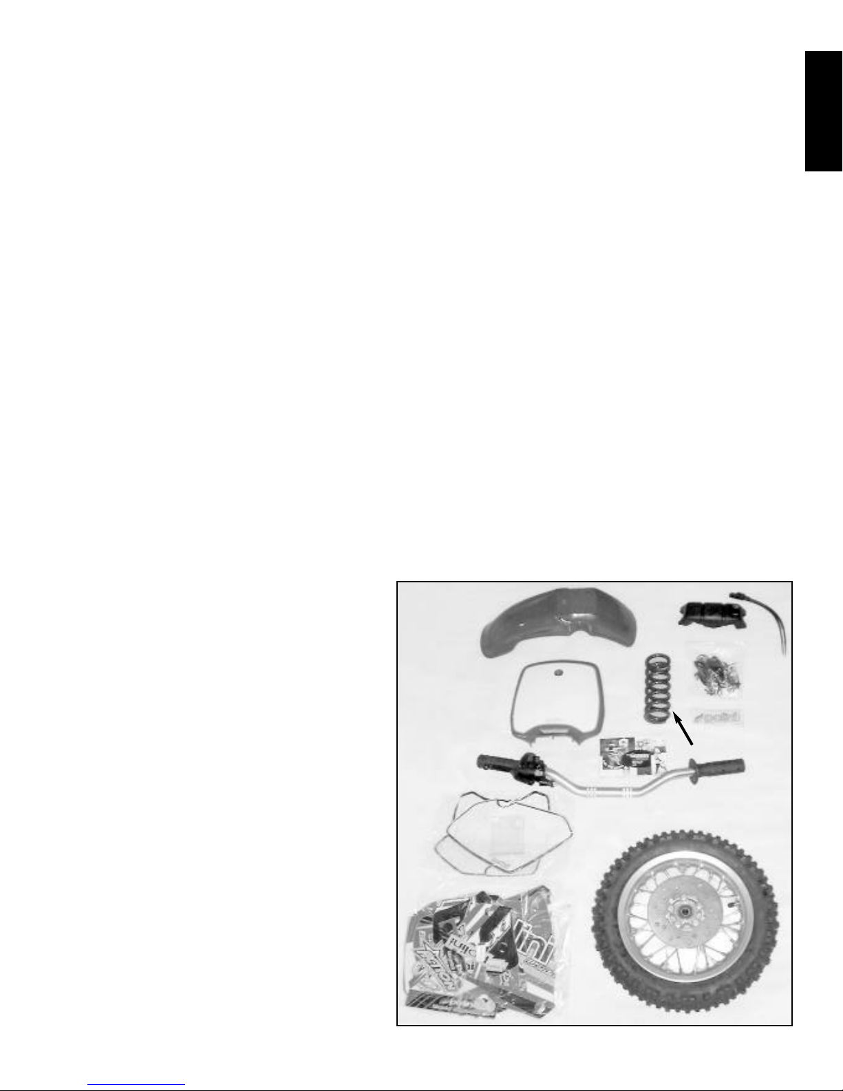
Open parts bag, and compare contents to photo. There should
be 2 footpegs with springs, bolts, & nuts, two bar clamps
with 4 allen bolts, 4 fender screws and washers, 1 brake cable
guide, 1 kill switch clamp assembly, 1 front number plate
screw with spacer, and 1 front axle pinch bolt. See photo I-2.
(Only works models come with optional graphics package)
Contents of shipping box
optional heavier
rear spring
hardware
package
II.1
.1
Page 3
Page 4
I
Begin by cutting the plastic zip tie straps securing the front and rear
calipers to their mounting brackets.
Install front fender using 4 phillips head screws M6x16 and 4 washers
M6x18x1.
Install the front wheel next. Spread brake pads enough to accept rotor,
then align front wheel with axle holes in forks. Insert front axle from
right side of bike, through front wheel and into the left fork. Using a 5⁄16”
or 8mm allen wrench, turn the axle until it is fully threaded into the left
fork, then torque to 50 Nm. Next compress the forks several times to
properly align the forks on axle. Install and tighten axle pinch bolt using a
6mm allen wrench to 25 Nm.
Install handlebar using 2 U-shaped bar clamps with 4 M8x30 socket
head bolts using 6mm allen wrench. Make sure gaps are even from front
to rear of bar clamps. Tighten bolts to 25 Nm. Install bar clamp pad using
2 zip ties provided. Install kill switch on left side of handlebar near grip
pointing up using 2 piece clamp assembly in hardware package.
Route cables as outlined in section II-4. (See page 8)
Adjust front brake lever (bar mounted rear brake lever also, if so
equipped) using adjuster on lever so that free play is from 4 to 5mm,
measured at gap between lever and and cable holder - See photo III-2.
Check wheels for free rotation and proper braking when levers are
applied.
Remove 2 screws from top of throttle housing and remove cover.
Install end of cable into top hole in throttle tube. Install throttle cover
making sure cable is in groove. Twist throttle repeatedly to check for any
binding or failure to return to rest position when released. Fix sticking or
sluggish throttles. Do not lube throttle grip assembly but remove and
clean as needed. Use a small piece of duct tape to secure cable to adjuster
to prevent setting from changing or cable from pulling out. Push cable
boot fully onto throttle housing, using a small zip tie on the end of the boot will help prevent dirt from entering. These tips also
apply to the carburetor end of the cable.
Install front number plate by inserting 3 fingers into holes in front fender, then insert phillips M5x30 screw using metric spacer
5.5 x 12 x 20. Spread the grey plastic front brake cable guide over cable, push into hole in front number plate.
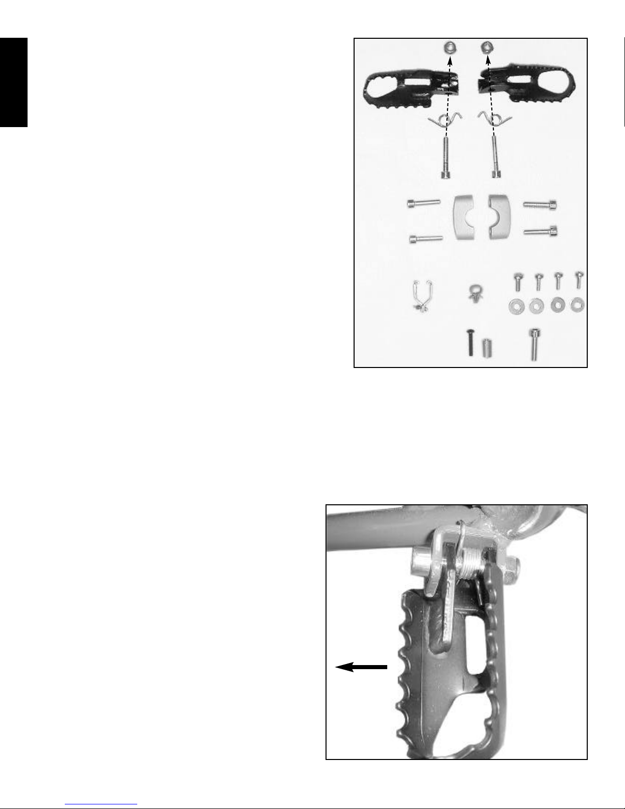
Install footpegs using SCS M8x40, a M8 lock nut, and footpeg spring. See photo I-3. If necessary, bend straight end of spring
down with a pair of pliers to tension footpegs more. To make spring easier to install, use a pair of pliers or a vise to compress spring,
then hold in position using a small zip-tie. Install spring and then cut zip-tie to release.
Inflate tires to 18 psi.
Fill radiator with approximately 27oz. (with dual radiators) of
Engine Ice®antifreeze (ready to use). See section III-4. Fill transmission through vent hole or level checking screw hole with 300
cc (10 oz.) Maxima brand MTL 75 gear lube for best results.
Remove checking screw and fill slowly in case some oil is already
in transmission. Do not overfill. See procedure in section III-6.
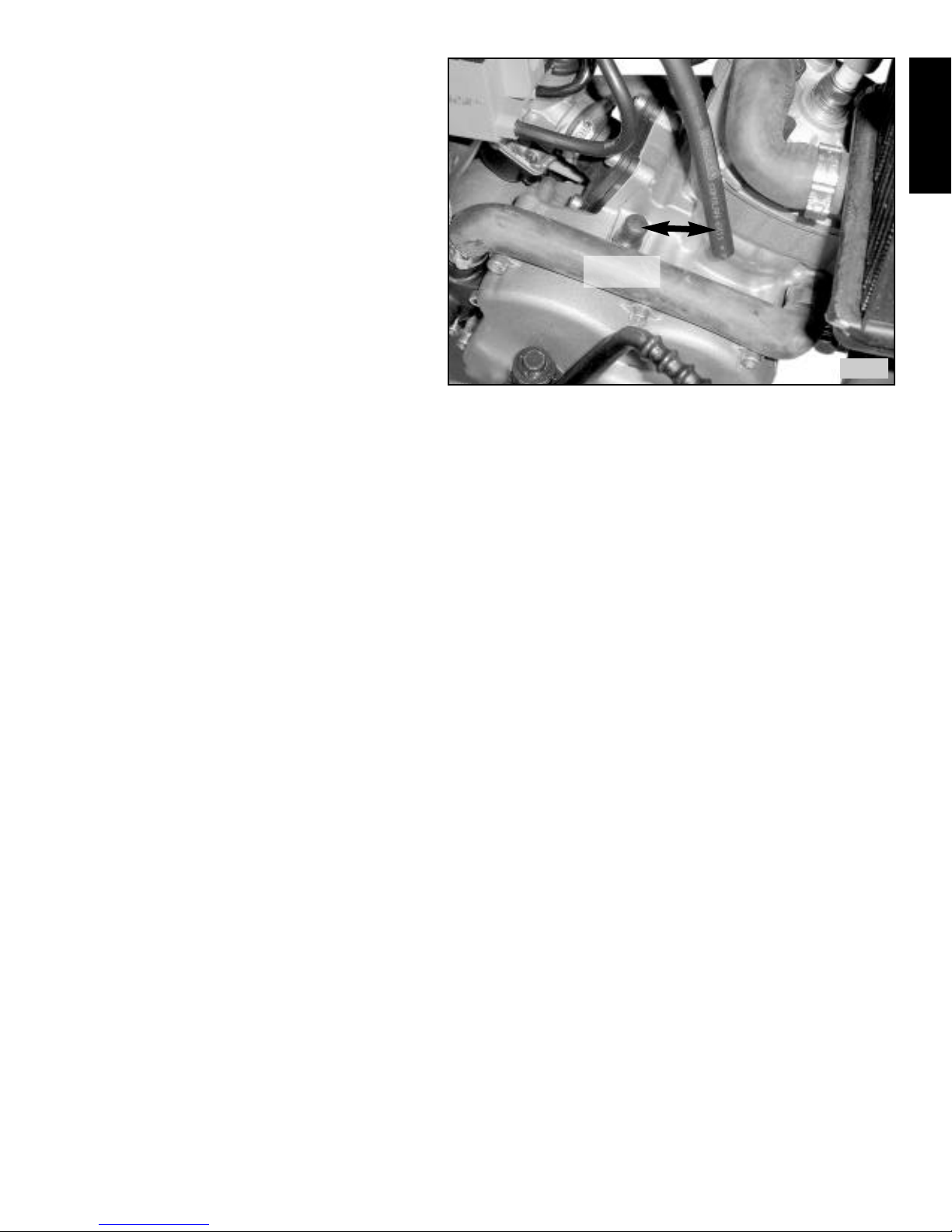
Remove rubber cap from crankcase vent fitting and push vent
tube onto fitting. (See photo I-4)
If kickstarter hits expansion pipe when folding in, remove pinch
bolt using a 5mm allen wrench and remove kickstarter. Insert
screwdriver blade into slot to loosen kickstarter on shaft if necessary. Reposition kickstarter rearward 2-3 splines and re-install.
Torque pinch bolt to 10 Nm.
Apply the decals last (if necessary). Remove the fuel tank with
shrouds attached before applying the decals to them. Try to apply
the decals in a warm, clean, well lit area and at least 24 hours
before the bike is to be ridden.
It is very important to properly prepare your bike’s plastic for
application of pressure sensitive decals. The plastic should be
cleaned with conventional soap and water, and any scratched areas
should be lightly sanded to make them smooth. The smoother the
surface the better the adhesion. Before you peel back the backing
on the decal, fit it in place and line it up properly. Tape it in position
All nuts, bolts and small parts are in a bag inside box.
Footpeg installation - left side shown.
kill switch
clamp
front number
plate screw &
spacer
front axle
pinch bolt
front brake
cable clamp
front fender
nuts & washers
front
II.2
.2
II.3
.3
Page 5
I
with masking tape, and notice where any curves and creases might occur. The curves and areas where the plastic
tapers in 2 directions will be the most difficult areas to
apply. When you’ve determined the best fit, tape one edge
of the decal securely in place, and remove the tape from
the opposite edge. Lift the decal up and spray a light mist
of water from a squirt bottle onto the entire plastic panel.
This will allow you to dampen the adhesive so it won’t
stick as well during the application of the decal and allow
repositioning if necessary without losing the the final bond.
Carefully align the decal and lay it on the plastic. If the
graphic is not fitting the panel correctly, you can peel it
back up and start over. Start pressing down near the center
of the graphic to ‘work’ the water and any air away from
the center and toward the edges of the decal. Pay extra
attention to creases and irregular areas where the graphic
needs to conform to the plastic in unusual ways. Take your
time and work from the middle of the decal to the edges
pushing out any water and air as you go. The water will
weep out the side of the decal as you reach the edges.
If you’re having trouble with an irregular area, use a blow dryer or heat gun to lightly warm up the decal in order to make it conform. The heat will soften the material, so that you can stretch or compress it as needed to make it fit. Use just enough heat to make
the material pliable without melting it.
3. Pre-ride checks
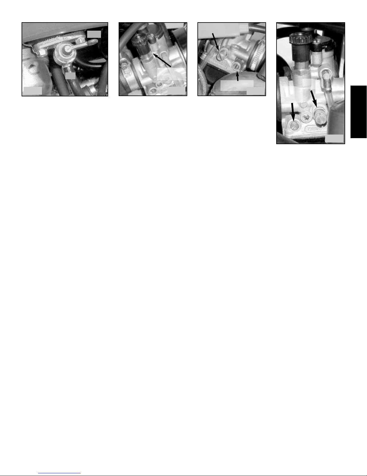
Initial startup - When motorcycle is at operating temperature, adjust idle speed to the lowest speed at which the motorcycle will run
smoothly by using idle adjustment screw. See photo II-6. Then adjust fuel metering screw. Roll on the throttle rapidly. If the engine
bogs or hesitates, try rotating screw clockwise (leaner) in 1⁄4 turn increments until hesitation ceases. If the engine surges or misfires,
rotate screw counterclockwise (richer) in 1⁄4 turn increments until bike accelerate smoothly. If the fuel metering screw has to be less
than 11⁄2 for proper running, consider using a leaner pilot jet. If fuel metering screw is more than 21⁄2 -3 turns out, install a leaner pilot
jet. The fuel metering screw is normally set from 11⁄2 to 21⁄2 turns out from fully seated. Never tighten fuel metering screw, just gently
turn in until it stops, then back out counting the turns to the desired setting. The fuel metering screw can cause overall jetting to be
too rich if it is turned out too far. Note that the fuel metering screw only affects the initial throttle response in conjunction with the
pilot jet until the needle jet takes over at 1⁄4 throttle and above.
Regular pre-ride checklist - Check chain tension and make sure chain is well lubricated and not worn. Check tire pressure, spokes,
all nuts & bolts, steering stem for binding or play, swingarm bolt, engine mounting bolts, oil & coolant levels and condition, lever
and throttle adjustment, & air cleaner. Look for broken or worn parts, leaking fluids, etc. Check brake calipers for proper freeplay
and accumulations of dirt. Clean and adjust as needed to provide proper function.
4. Basic operation & control functions
Engine startup - Make sure motorcycle has premix fuel, transmission oil and coolant. Make sure air cleaner is installed and proper-
ly oiled. Note that arrow on air cleaner and filter cover must point to front of motorcycle.
Turn fuel valve to ON position (vertical position). See photo II-3.
If engine is cold, lift the choke knob on carburetor and rotate about
1
⁄8 turn so it stays in the up position. See photo II-4.
Squeeze brake lever to prevent sudden movement upon starting.
Motorcycle is always in gear and may move suddenly when started or whenever throttle is applied.
Push kickstarter down until slack is taken up, then kick briskly with throttle closed. If necessary, open throttle slightly and hold
while kicking. Motor should start readily. If adult is starting bike, use restraint not to damage kickstarter gears with excessive
force! If bike will not start, find and fix problems rather than just kicking harder! As engine warms, turn choke knob to return
it to the closed position and apply throttle slightly until bike idles without stalling.
To stop motor, depress kill switch until motor stops. If motorcycle will not start and there is a strong smell of fuel, the engine is
flooded. Turn off choke, open throttle fully and hold open, and kick motor approximately 10 times to clear engine of excess fuel.
Release throttle and try starting again. If engine still won’t start, remove sparkplug and inspect. If plug is wet with fuel, replace plug.
If plug seems to be dry, check fuel valve position and carburetor float and needle valve assembly for proper function.
Remove rubber cap, install vent tube onto vent fitting.
remove &
discard cap
II.4
.4

Page 6
I
I
Break in - The initial startup and running of the engine is crucial for long life and full power potential. Always warm engine for a
few minutes before riding motorcycle. Do not idle for extended periods - note that water pump does not circulate when rear wheel is
not turning. When starting for the first time, allow to warm for 1-2 minutes, and then ride motorcycle carefully for about 10-15 min utes. Avoid steep hills, mud, sand or other heavy loads on motor. Use partial throttle only, and vary speed when riding, do not maintain constant speed while breaking in motor. Allow motor to cool thoroughly. Repeat as above, gradually increasing throttle for
another 15 minutes. Allow to cool. Break in is now mostly complete. Change transmission oil at end of day. Check all fasteners for
loosening, check chain tension and brake lever(s) adjustments.
Control Operation - Twist right throttle grip to engage clutch and accelerate. Apply enough gas to fully engage clutch, do not rapidly engage/disengage clutch or premature wear will result. To slow or stop, release throttle and apply front and rear brakes evenly.
Apply brakes while traveling in a straight line until proficient in advanced braking techniques. Note that the front brake is applied
with the right hand lever and the rear brake is applied with the right foot lever (or left hand lever, if so equipped).
5. Control adjustment
Brake Adjustment - To adjust brake lever, (front brake and handlebar mounted rear brake), loosen knurled lock nut, and adjust
threaded adjuster to obtain proper freeplay of 4-5mm as shown in photo III-2. If unable to obtain correct adjustment at brake lever,
adjust play at caliper (see section III-9). Recheck freeplay at lever and make any final adjustments.
Brake pedal - The rear brake pedal is adjusted at the rear caliper. Check the movement of the caliper arm, it should be 5-10mm
measured at the tip of the arm. Adjust caliper as needed using the same procedure as for the front brake caliper (see section III-9). If
pedal has too much or not enough free play after adjusting caliper, loosen cable clamp on caliper arm and adjust cable position to
obtain desired pedal free play. The tip of the brake lever should move between 1⁄4˝ to 3⁄8˝ before tire locks.
Throttle adjustment - With engine off, check throttle grip to make sure there is a small amount of freeplay (1⁄8˝ max). Check again
while turned all the way to the right and all the way to the left. Make sure there is some slack in the throttle cable between where it
is tied to the chassis and where it connects to the carburetor. Start engine and turn bars full left and right and make sure idle does not
change. Adjust freeplay by pulling boot off throttle housing, then loosen locknut and turn adjuster screw into housing for more
freeplay, turn screw out of housing for less freeplay. Tighten locknut and push boot back onto throttle housing.
Bar angle - The angle of the bars can be adjusted to fit different riders. Taller riders might want to rotate bars slightly forward, while
shorter riders can rotate bars backwards to make them easier to reach. Make only small adjustments to bar angle so that the grip
angles do not become excessive.
Lever angle - The front brake lever (and rear if so equipped) can be adjusted so they are horizontal or angled downward. Aggressive
riders who spend most of their time standing will want the levers angled somewhat downward for a more natural grip while standing. Beginning riders will generally prefer a nearly horizontal lever position, especially if they have small hands.
II. GENERAL INFORMATION & SPECIFICATIONS
1. Description - diagram of motorcycle components & controls
rear brake
kickstarter
throttle
fuel cap
front brake
kill switch
throttle &
front brake
lever
cable
clamp
IIII.1
.1
IIII.2
.2
Page 7
I
I
2. Specifications
Length - X1: 50˝ X3: XX X5: XX
Width - X1: 241⁄4˝ X3: XX X5: XX
Height - X1: 32
3
⁄4˝ X3: XX X5: XX
Wheelbase - X1: 343⁄8˝ - 355⁄16˝ X3: XX X5: XX
Seat height - X1: 24˝ X3: 28˝ X5: 32˝
Footpeg height - X1: 93⁄4˝ X3: XX X5: XX
Ground clearance - X1: 8˝ X3: XX X5: XX
Wet weight (no fuel) - X1: 97lb. X3: XX X5: XX
Fuel capacity, type - 1 gallon - 93 octane pump gas (must be mixed with premix oil)
Oil premix ratio - 40:1 mixture of fuel and Maxima K2 premix oil
Chain - Regina 415, 91 links (X1) X3: XX X5: XX
Steering head angle - 20˚
Forks - conventional hydraulic, 51⁄2˝ travel, X1: 160cc 10wt fork oil, X3 & X5: 180cc 10wt fork oil
Shock, gas charged mono-shock, adjustable preload, compression & rebound dampening -
shock springs specs, free length, XX kg/cm, Optional shock spring specs, free length, XX kg/cm,
51⁄2˝ suspension travel ??
Engine type - single cylinder, 50cc case reed 2-stroke motor, liquid cooled
Bore & stroke - 40.2mm x 39.3mm
Compression ratio 14.5:1
Redline - 13,700 rpm
Transmission oil capacity - 10 oz. (300cc)
Coolant capacity - approx. 27oz. Engine Ice®antifreeze (dual radiator models)
Carburetor model - X1: Dell’Orto PHBG19, 19mm (X1 models sleeved to 14mm for AMA compliance) X3: 21mm, sleeved to
19mm X5: XX
jet sizes - X1: main: 88, needle: W3 @2nd clip from top, needle jet: 262, pilot jet: 55, choke jet: 60, fuel metering screw: 21⁄2 turns
from bottomed. X3: XX X5: XX
Float level - ???!!!
Clutch - Works: automatic centrifugal 3 shoe type, engagement rpm adjustable from 5000 to 7000 rpm Std: automatic 2 shoe clutch,
adjustable
Gear ratio - 12T front, 42T rear - Optional 13-14T front and 36-48T rear
Electrical system - Works: Selettra CDI P3356
Spark plug - NGK R5671A-11 or B9EV, gap .024”
Timing specification - 1.6mm BTDC
Wheels - 10” front & rear, straight pull spokes
Tires - Pirelli MT32A 2.50 x 10 @18psi
Brakes - Disc brakes front and rear with mechanical calipers, front brake hand lever, rear brake foot lever (works) or rear hand lever
(std)
Color - Blue & white
Fuel valve - Off position
choke knob
X1
idle screw
fuel metering
screw
Idle, fuel metering screw - X1
Choke knob - X1
lift &
1
⁄8 turn to engage choke
Idle, fuel metering screw
X3 & X5
idle
screw
fuel
metering
screw
IIII.3
.3
IIII.4
.4
IIII.5
.5
IIII.6
.6
choke
choke
IIII.5
.5
IIII.6
.6
IIII.4
.4
IIII.3
.3
ON
OFF

Page 8
I
I
3. Chassis number, production year
4. Cable & hose routing
Route cables, hoses and wires as per photos II.9 and II.10. Be sure seal cable ends with
tape and leave some slack in throttle cable near carburetor. Use a small zip-tie to secure cable
boots and seal out dirt and water. Make sure to always replace vent hose onto vent fitting to
prevent contamination of transmission. Check and clean carburetor vent hoses as needed to
keep carburetor working properly. Clogged vent hoses can cause the carburetor to malfunction and can result in engine damage.
5. Fuel & oil requirements
Fuel requirements - Hi-test pump gasoline is recommended for your motorcycle with a min-
imum octane of 92-94. This octane rating is necessary to prevent possible detonation (pinging) and damage to piston from low octane fuel. If “pinging” or “knocking” occurs, check ignition timing, jetting, plug color, and
piston dome for carbon deposits. An air leak can also cause these symptoms. The fuel must be mixed with the proper type and
amount of oil or severe engine damage will result.
Note: Race fuel is not required unless the compression of the motor has been increased. Race fuel burns slower and will decrease the
acceleration of the motorcycle. Even with increased compression, a 50/50 mixture of race gas and pump gas should be sufficient to
prevent detonation.
Oil requirements - The fuel must be mixed with the proper type and amount of oil prior to fueling the motorcycle. The oil is
required to lubricate the crankshaft bearings, rod bearings, piston, rings and cylinder walls. The transmission oil only lubricates the
clutch and transmission, it does not lubricate the engine components in a 2 cycle engine. The oil must be specifically recommended
for premix use in motorcycles or the oil may not provide enough lubrication, cause piston rings to stick, cause heavy deposits in
engine and foul spark plugs, or separate from the gasoline. The use of Maxima brand K2 premix oil is strongly recommended. If this
product can not be obtained, use a synthetic or semi-synthetic 2-stroke premix oil specifically for motorcycle use.
The oil must be mixed with the fuel at a ratio of 40:1 (40 parts fuel to 1 part oil) Graduated containers can be purchased which
show the proper amount of oil for various quantities of fuel for any common ratio. One common type is called the “Ratio Rite™,”
which can be purchased at most motorcycle stores. Otherwise, to obtain a 40:1 ratio, use 3.2 fluid ounces of oil per 1 gallon of fuel.
(6.4 ounces for 2 gallons, 8 ounces for 21⁄2 gallons, 16 ounces for 5 gallons, etc.) If measuring in liters, use 25cc oil per litre of fuel.
To mix oil with fuel, fill mixing container with 1⁄2 the desired amount of fuel. Add the proper amount of oil (for the total amount of
fuel) to the fuel in the container. Tightly cap and secure vent on container, then vigorously swirl and slosh fuel to mix oil. Add other
half of fuel and continue to mix thoroughly. Mix at least 1-2 minutes. Release fuel pressure using vent before opening container, be
cautious of flammable fumes. Never add oil to gas tank of motorcycle! Always mix fuel and oil thoroughly in a separate container
before fueling motorcycle, otherwise the oil will clog the fuel filter and jets in the carburetor and cause severe starting and running
problems. Do not store gasoline any longer than necessary, as it loses its potency over time. An approved metal container is best for
storage. Do not store fuel mixed with oil. Mix only enough fuel and oil to be used in a short time. Take great care that water or dirt
does not contaminate fuel or gas tank.
Model & year
Chassis number
Cable, hose & wiring routing
IIII.8
.8
IIII.9
.9
IIII.10
.10
leave some
slack in throttle
cable
IIII.7
.7
IIII.8
.8
IIII.9
.9

Page 9
I
I
6. Definition of units/conversions
1˝ = 25.4mm
1mm = .0394˝
1cm = 10mm
1cc = 1 mL = .0338 oz. (fluid)
1 oz. (fluid) = 29.565 mL
1 oz. (weight) = 28.35 grams
1 gram = .035 oz. (weight)
1 liter = 1.057 quarts = 2.114 pints = 4.228 cups
1Nm = .102 m/kg
1m/kg = 9.804 Nm
1 lb. = 2.2 kg
1 ft/lb = 1.357 Nm = .1383 m/kg
1 barrel (beer) = 31 gallons
1 kilometer = .621 miles
To covert degrees Fahrenheit to Celsius: subtract 32 and divide by 1.8
To convert degrees Celsius to Fahrenheit: multiply by 1.8 and add 32.
For any other conceivable conversions you might need, consult www.onlineconversion.com
7. Torque values
Alternator nut ..............................42 ft/lbs (57Nm)
Brake rotor bolts..........................
Case bolts ....................................7 ft/lbs (10 Nm)
Clutch nut ....................................42 ft/lbs (57Nm)
Cylinder nuts................................10 ft/lbs (13.6 Nm)
Engine mount bolt (front)............42 ft/lbs (57Nm)
fork pinch bolts............................11 ft/lbs (15 Nm)
Front axle ....................................37 ft/lbs (50 Nm)
Front axle pinch bolt ....................18 ft.lbs (25 Nm)
Fork cap ........................................4 ft/lbs (5 Nm)
Fork slider retaining bolt ............20 ft/lbs (27.1Nm)
Fuel tank screw............................snug by hand only
Handlebar clamps ........................18 ft.lbs (25 Nm)
Lower shock nut ..........................33 ft/lbs (45 Nm)
Rear axle nut................................37 ft/lbs (50 Nm)
seat bolt........................................snug by hand only
Spark plug....................................20 ft/lbs (27.1Nm)
Sprocket bolts ..............................
Steering stem adjusting nut..........adjust by hand until play is gone
Steering stem top nut ..................18 ft.lbs (25 Nm)
Swingarm nut ..............................37 ft/lbs (50 Nm)
Upper shock nut ..........................33 ft/lbs (45 Nm)
General torque values for fasteners not listed above
bolt size hex head size Socket head size ft/lb m/kg Nm
5mm bolt . . . . .XXmm head . . . . . . . . . . . . . . . . .3.6ft/lb . ..5m/kg . . . .5Nm
5mm screw . . . . . . . . . . . . . . . . . . . . . . . . . . . . . . .2.9ft/lb . .4m/kg . . . . 4Nm
6mm bolt . . . . .10mm head . . . .5mm . . . . . . . . . .7ft/lb . . .1m/kg . . .10Nm
6mm screw . . . . . . . . . . . . . . . . . . . . . . . . . . . . . . .6.5ft/lb . ..9m/kg . . . .9Nm
8mm bolt . . . . .12mm head . . . .6mm . . . . . . . . . .16ft/lb . .2.2m/kg . . 22Nm
10mm bolt . . . .14mm head . . . . . . . . . . . . . . . . . . .25ft/lb . .3.5m/kg . . .35Nm
12mm bolt . . . .17mm head . . . . . . . . . . . . . . . . . . .40ft/lb . .5.5m/kg . . .55Nm
14mm bolt . . . .19mm head . . . . . . . . . . . . . . . . . . .61ft/lb . .8.5m/kg . . .85Nm
16mm bolt . . . .22mm head . . . . . . . . . . . . . . . . . . .94ft/lb . .13m/kg . .130Nm
note: bolt size refers to thread size, not the wrench size used on head of bolt!
bolt head sizes are for standard hardware, use torque values in service sections if provided.
5
6
8
10
12
14
16
Actual bolt sizes

I
I
I
III. MAINTENANCE, ADJUSTMENTS & SERVICE PROCEDURES
1. Notes & warnings
Use caution when working on or around motorcycle. Note that exhaust, engine, cooling system and brake parts may be
extremely hot after operation. Be very cautious of moving parts, especially the chain and sprockets which can draw clothing,
hair and fingers into sprockets, chain guard or chassis causing severe injury. Do not operate motorcycle in a confined area as
exhaust fumes can be fatal. This motorcycle is not equipped with a spark arrester and could discharge sparks from the muffler
which could ignite any nearby combustible materials causing fire or explosion. Do not use gasoline or other highly flammable liquids to clean parts or air filter. Fire or explosion may result. Mix gas and fuel motorcycle only in well vented areas free of
sparks or flame. Note that gasoline fumes can travel long distances along the ground and readily ignite. Safety glasses are nec-
essary whenever working with oils or chemicals, whenever impact tools are used, or when tool breakage would result in flying metal
fragments. Any mechanism with a spring has the potential for flying parts and eye injury. The rear shock is charged with nitrogen
gas under very high pressure. It is not serviceable by the owner. DO NOT disassemble or discharge shock absorber. Use hearing protection to guard against exhaust noise, realize a helmet provides only limited protection from exhaust noise. When using wrenches,
adjust wrench so it can be pulled rather then pushed to prevent injury if wrench or sockets slips. Use caution with open end wrenches as they can easily round off fastener heads.
2. Maintenance & lubrication schedule chart
Air cleaner - Clean and reoil daily or after each moto to prevent motor failure and reduced performance.
Transmission oil - change after every race, or at end of riding day.
Chain - check tension and lubricate before every ride, adjust or replace as needed. Reoil after riding in damp conditions.
Clutch - disassemble and clean clutch assembly frequently, every 2-3 races at least. Inspect kickstarter gears at this time.
Ignition cover - remove cover and wipe dry after each ride or after washing bike to remove condensation.
Piston rings - replace as often as every 3-5 races with expert rider, less often with less aggressive riders.
Piston, pin, rod bearing & circlips - replace as often as every 8-10 races with expert rider, less often with less aggressive riders.
Coolant - change yearly, make sure there is at least a 50/50 mixture of antifreeze if freezing temperatures are possible.
Steering bearings - Check daily for looseness or play. Adjust and regrease as needed.
Swingarm - Check often for looseness. Regrease several times a year. Replace bushings if any play is evident.
Sprockets - check for worn or curved teeth each time chain is adjusted.
Chain roller & wear pads - check roller for free rotation when checking chain. Make sure roller is not bent or damaged. Check
chain wear strips on swingarm and chain guide frequently. Replace as needed to prevent chain from damaging motorcycle.
Spokes - Check after each race or after each day of riding for looseness or damage.
Wheels & tires - check wheels after each race for dents, cracks or other damage. Check tires for cuts, damage or wear. Check tire
pressure daily and adjust for riding conditions.
Shock - Check shaft area daily for signs of oil leakage or damage. Check swingarm and shock bushings for looseness.
Forks - Check forks daily for leaking oil or damage to tubes. Make sure forks are not twisted check for smooth operation.
Spark plug - check sparkplug color and condition after each race or end of riding day. Adjust jetting to keep plug from fouling or
overheating.
Silencer - If bike seems to be getting louder, replace packing and decarbonize inner tube.
Expansion pipe - check daily for large dents, damage or leakage. Remove carbon from headpipe when pipe is removed. Have large
dents fixed, or any dents within 8” of the cylinder. Replace o-rings on pipe as needed to maintain a good seal.
Footpegs - check daily for proper operation, pegs should spring back into place. Make sure pegs are not bent or overly dull.
Handlebars - check bars after any crash for bending. Look for cracks near bar clamps. Replace bars that have been straightened
more than 2 or three times, or if bar is badly bent. Aweakened bar can snap suddenly causing injury to rider.
Throttle - check throttle for proper operation each time before bike is started. Remove and clean inside of grip and bar as needed.
Grips - check grips daily for wear or looseness. Replace as needed. Use grip glue & safety wire to help hold grips in position.
Calipers & pads - check pad wear and caliper function daily or after each race. Replace pads and clean calipers as needed.
Brake lever - check lever daily for damage or wear. Make sure lever is at proper angle for both seated and standing positions. Leave
lever clamp loose enough to allow clamp to rotate during crash rather than breaking lever. Check and adjust freeplay as needed.
Brake pedal - Check pedal daily for damage and proper freeplay. Adjust rear caliper as needed.
Reeds - Remove and inspect reed block during every ring change. Check reeds for signs of wear, fraying and cracking. Make sure
reeds sit flat and seal well. Replace at any sign of wear or damage or at least once a year, more often for expert riders.
Nuts & bolts - Check all nuts and bolts regularly. Make sure to check engine mounting bolts and swingarm bolt frequently.
3. Maintenance preparation
Before servicing, clean motorcycle to allow better inspection and repair, especially before any motor work to prevent dirt from
falling into motor. Closely inspect entire motorcycle for broken or damaged parts on a regular basis.
Page 10

I
I
I
4. Coolant
Filling cooling system - When engine is cool, unscrew radiator cap slowly to release any pressure safely. Do not open when warm
or hot! Fill the radiator until liquid reaches opening. Wait a few minutes for the coolant to reach all the internal cavities, top of f
coolant as needed. Coolant must be visible over internal fins, but does not have to reach all the way to filler neck. Screw radiator cap
back on. Start engine and run for a few minutes, making sure to engage clutch and spin rear wheel. After engine cools, remove cap
and recheck coolant level. Add coolant if required. Screw cap back on. Coolant level must always be checked when engine is cool.
Check each day before riding, and after every race. If the radiators were just filled, some coolant will initially escape as the motor
warms up. If coolant suddenly begins to discharge from the vent tube, look for a combustion chamber leak, improper timing, or lean
jetting. Use motorcycle coolant only, automotive antifreeze contains abrasive silica and may damage water pump seals. Read container before use to determine if antifreeze needs to be diluted before use. Use antifreeze if freezing is possible to prevent engine
damage. Engine Ice®motorcycle coolant is recommended as it will lower operating temperatures and is non-toxic. Keep ALL
antifreeze away from children and pets!
Note: Water pump does not turn unless motorcycle is moving. Do not idle motorcycle for extended periods to prevent overheating.
5. Air filter cleaning
It is crucial to performance and engine life that the air filter be clean and properly oiled at all times. Proper cleaning is necessary to
remove dirt which could severely damage the engine, dirt buildup will also cause the motorcycle to run very rich and lose power rapidly. The filter should be cleaned and re-oiled approximately every two hours of use under normal conditions, much more often during
dusty or wet conditions. Cleaning filter or using a freshly oiled air filter before every race is advisable. If water is used to clean the filter, the filter MUST be completely dry before re-oiling, or the water will evaporate leaving un-oiled portions of the filter which will
allow dirt and dust to pass directly into the motor. If the air filter gets soaked in water during use, it must be cleaned as soon as possible
because the water can displace the filter oil. Performance wise, having a clean air filter is the single most impor tant item on the
motorcycle and requires the most maintenance. Purchasing one or more extra filters is a very good investment.
UNDER NO CONDITIONS USE GASOLINE OR OTHER FLAMMABLE LIQUIDS TO CLEAN FILTER.
In addition to creating an extreme fire hazard, these liquids will damage the filter foam over time, making it brittle and dissolving
the glue used to make the filter.
1. Clean your filter with Maxima, Twin Air air filter cleaner, or kerosene to remove all the oil residue.
2. Next, wash your filter twice with dish soap and hot water. Rinse a third time. Do not stretch or twist the filter. Be careful not to dam-
age or crush the seams at the corners of the filter.
3. Let filter dry completely, or else water will prevent oil from properly coating filter and will allow engine to suck dust through filter.
Use a hair dryer or leave filter in the sun to dry it more quickly.
4. Now that filter is totally dry, hit the filter on your hand to get all the dirt out. If you do this over a piece of paper or cardboard you
can see & hear the dirt falling onto it.
5. Now apply the filter oil, Maxima FFT Foam Filter Treatment is preferred as it is not prone to dripping into the carburetor and is
resistant to washing out by water or gas vapors. Using a plastic bag, put your filter into it and pour in some filter oil. Totally saturate
the filter with oil, making sure there are no dry spots. Squeeze out excess oil. Grease the groove on the aircleaner where it presses
onto the airbox to prevent air leaks. Make sure to use extra grease in the corners. Install filter with arrow to front, making sure groove
in air cleaner fits over sides of air box. Press filter cover over filter with arrow pointing to front to secure filter in place. Note that
spray air filter lubes must also be liberally applied, then squeezed, then the excess removed to insure full coverage. For racing use, a
long zip tie, or several attached together can be wrapped completely around air box and filter cover to insure positive retention.
6. Changing transmission oil
Change transmission oil often to remove clutch wear particles and other contaminants from transmission. Changing oil frequently will greatly reduce the amount of clutch adjustment and cleaning required as well as reducing wear in the transmission. Change oil after every race or at end of each riding day. Note that the Maxima MTL 75 transmission fluid is specifically for-
mulated to extend clutch life and is strongly recommended!
To change the transmission oil, support motorcycle in a level position. Unscrew drain bolt on bottom of transmission cases using a
6mm allen wrench and remove drain screw from clutch side cover to fully drain oil. Drain oil while it is hot from riding to facilitate
draining of oil and wear debris. Dispose of used oil properly. Replace the transmission drain bolt and torque to 15 ft/lbs, install and
snug the transmission cover screw. Refill transmission using 10 oz. of recommended gear oil (Maxima MTL 75) through the upper
level checking screw. The vent hose fitting can also be removed and oil added there. (vent hose fitting is behind the coolant hose at
rear of cylinder) Aketchup squeeze bottle with a pointy tip is useful for injecting oil into screw hole. Mark the proper level on the
container so the right amount can be dispensed in the future without measuring. Check oil level after filling.
To check oil level, support bike in a level position and remove oil level check screw from side of case (screw is below kickstarter).
Oil should flow from hole. Add oil or allow excess oil to drain as required.
Page 11
Page 12
I
I
I
7. Seat removal
To remove seat, loosen large screw at rear of seat using a coin, or a wide, flat screwdriver. When screw is loose, lift up slightly on
rear of seat and slide seat to rear to remove.
To install seat, note slot underneath seat at front. This slot must engage the bolt head on top of the fuel tank. Also note hook
underneath seat. This hook will engage rear of fuel tank. Place seat on motorcycle with slot slightly to rear of bolt on tank. Slide seat
forward, making sure slot engages bolt, and hook engages rear of tank. Push seat forward firmly, then snug screw at rear of seat. Do
not overtighten. Make sure front of seat is properly installed by attempting to lift upwards.
8. Tank removal, checking, gas filter
To remove tank, first remove seat. Use phillips screwdriver to remove tank mounting screw. Disconnect vent hose from fuel cap.
Check to make sure fuel valve is off, then remove fuel line from fuel valve. Lift tank upwards to remove. Make sure rubber pads
located at front and rear of tank in recess that fits over frame do not get lost. A little weatherstrip cement can be used to secure the
pads permanently to the bottom of the tank. Use care in setting fuel tank down so that the fuel valve does not stick into dirt or
debris and get clogged. Make sure tank does not spill gas or vent fumes near flame or sparks.
To install tank, make sure fuel valve is not clogged with debris, run a little fuel into a container if there is any question and clean
as required. Make sure two rubber pads are in place inside fuel tank frame recess. Line slots in tank up with two rubber cylinders on
frame and lower tank onto frame. Install phillips bolt into grommet located to the rear and top of the fuel tank. Snug screw but do
not overtighten. Reattach vent hose. Attach carburetor fuel line to fuel valve, making sure end of line is free of dirt or debris.
To check fuel filter, drain fuel and remove tank. Remove two screws attaching fuel valve to bottom of tank using an 8mm socket.
Pull valve out of tank. Clean fuel filter carefully, do not attempt to remove filter from valve. Insert valve into fuel tank making sure
o-ring is in place and not damaged. Install 2 screws and gently snug against valve. Do not overtighten screws or they will strip the
threads in the tank. They only need to be snug for the o-ring to seal effectively. For racing use, you may wish to turn the fuel valve
around so the lever faces inwards. It may be necessary to file the bump on the end of the lever for clearance.
9. Braking system
The motorcycle uses cable operated mechanical disc brakes. Proper brake function is crucial for safe operation of motorcycle.
For proper operation, they must be kept clean and lubricated and adjusted to specifications. If brake pads are allowed to wear
out, they may damage the discs, requiring costly replacement. Muddy conditions and improper servicing will lead to rapid brake pad
wear and possible loss of braking. Calipers will need to be disassembled, cleaned and lubricated after riding in muddy or wet conditions.
Front and rear calipers are the same except for the mounting bracket. The foot activated rear brake can only be adjusted at the
caliper, using the adjusting screw on the caliper and cable position adjustment. Replace brake pads when friction material is less than
1mm thick or if the pad surface is badly scored or damaged. Use grease cautiously when lubricating caliper assembly so that grease
does not come out and contaminate the pads or disc.
Check brake rotors for damage, wear and wobble. If wear is noticeable check thickness of rotor several times across face, replace
rotors if they measure less than 2.5mm (.098˝). Use threadlocker on brake rotor bolts, and torque to XX ft/lbs.
shaft
pad
retaining
bolts
caliper lever
hold hex nut with
wrench, use allen
wrench to loosen
set screw & adjust
cable
nut
III
III.1.1
III
III.2.2
4- 5mm
Front caliper components, rear similar.
Adjust front brake lever play to 4-5mm as shown.

I
I
I
Brake adjustment - As the brake pads wear, adjustment to the caliper will become
necessary to restore proper freeplay at the brake lever. Astroke of about 5-10mm
should be obtained as measured at end of the caliper lever. To make this adjustment,
unscrew caliper arm nut (2) and rotate threaded shaft (1) clockwise with a 2.5mm
allen wrench until the correct stroke of the caliper lever is restored. Then, while
holding the threaded shaft against rotation, tighten the caliper arm nut (2) again (to
60 in./lbs), and check that the wheel is not dragging or locked. Make final adjustments at the brake lever adjuster as needed. See illustration III.1
Front brake caliper service
Support bike on stand with front wheel off ground. Remove front wheel. Loosen
cable clamp screw using a 2.5mm allen wrench while holding cable clamp body
with an 8mm wrench. Remove cable from arm. Be careful not to lose cable clamp
assembly. Caliper will now slide off pins on mounting bracket. Remove two pad
retaining bolts using a 3mm allen wrench and remove pads. Remove caliper lever
using a 8mm wrench to remove retaining nut. Note position of lever spring.
Remove two caliper housing bolts using a 4mm allen wrench. Push on lever shaft to
remove caliper piston from housing, make sure not to lose two small rollers. Remove
cylinder from center of piston. See photo III-4.
Clean caliper housings thoroughly, especially the piston bore. Clean piston assembly and make sure allen screw turns freely.
Lubricate allen screw and piston cylinder carefully so excess lubricant does not end up on pads or disc. Lightly grease two rollers
and insert them into piston bore, using a little grease to hold them in place. Lightly grease ramps on back of caliper piston and insert
piston back into caliper housing. Assemble caliper housing using two bolts, torque to XX ft/lbs. Then insert pads with friction materials facing each other and install two pad retaining bolts and torque to XX in/lbs. Install lever spring and caliper lever and loosely
install nut to retain lever. Push caliper onto mounting pins and reinstall front wheel. Spread pads to insert disc between pads. If disc
will not fit between pads, turn allen screw on caliper lever shaft counterclockwise to loosen pad adjustment. Attach brake cable to
caliper lever and adjust caliper free play. Tighten caliper lever retaining nut to 60 in/lbs. Adjust cable position and brake lever as
needed.
Rear brake caliper service -
Support bike on stand with rear wheel off ground. Remove rear
wheel. Proceed with service as for front brake caliper. Note that rear brake mounting bracket slot must
engage pin on swingarm to prevent rotation, and that pedal freeplay is adjusted only at the caliper.
10. Expansion pipe & silencer, repacking
The exhaust system on your Polini needs regular service to properly quiet the bike and maintain
peak power. The silencer uses fiberglass packing to reduce sound. If the packing becomes saturated
with oil, or burnt and fragmented the exhaust gases will be much more turbulent in the silencer
which will noticeably reduce power output as well as making the bike much louder.
The expansion pipe should be checked for cracks and large dents on a regular basis. Small dents
on the pipe will not affect power much unless they are located within 6-8 inches of the cylinder.
Make sure to replace the o-rings on the pipe when servicing motor. If the o-rings leak, power will
be reduced in addition to the mess leaking oil will cause. When pipe is removed, check inside of pipe where it joins the cylinder for
deposits of oil and carbon. Remove any deposits with solvent and a scraper. If cracks or holes are found, have welded or replace
pipe. Most dents can be fixed by companies specializing in this service. Make sure pipe mounting spring(s) are in place and tight.
Front caliper assembly
III
III.3.3
lever
arm
hold “nut”
and loosen set
screw to adjust
cable
rollers
III
III.4.4
III
III.5.5
Grease ramps and rollers &
lubricate adjusting screw
grease
lube
Exploded view of caliper assembly.
Page 13
Page 14
I
I
I
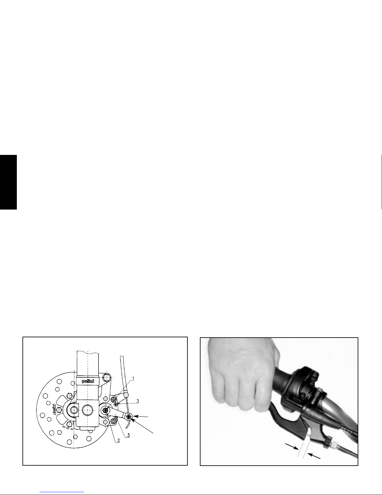
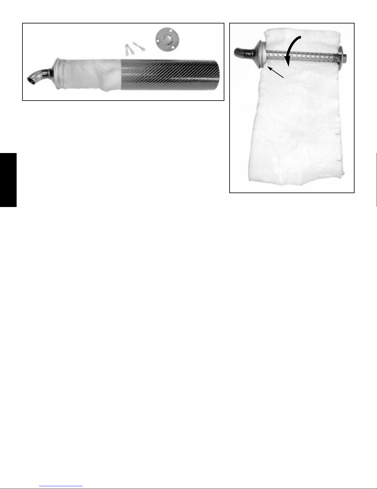
Repacking silencer - To service silencer, remove right side panel/number plate.
Remove bolt and clamp securing silencer to frame using a 6mm allen wrench.
Twist and pull silencer off pipe. Remove three bolts at front of muffler using a
4mm allen wrench. Hold rear section of silencer with one hand and pull outer
body of silencer off with other hand. Remove all remnants of silencer packing
from both sections. If holes in inner tube are partially or fully clogged, use a drill
bit of the proper size to remove the deposits from all the holes. Use a wire brush
on the outside to help loosen deposits. Purchase fiberglass packing made for
motorcycle silencers. If necessary, cut packing to the width of the silencer inner
tube by about two feet long. Starting at one end, roll the packing material around
the silencer inner tube, tucking the material into the endcap as needed. Wrap
material snugly, but not so tight as to compress the material more than a little bit.
If the packing will not fit into the outer body, unroll the packing a few inches
and trim off material until the outer body will fit snugly. Slide the outer body most of the way on, then seal the endcap with a light
coat of silicone sealant to help prevent oil from dripping. Slide the outer body over the endcap, align the three holes and insert and
tighten the three bolts. If oil drips out of silencer, a leaner main jet may be indicated. See section III-18 for testing procedure.
11. Cables - adjustment & lubrication
Check throttle and brake cables frequently for binding or damage. Check for frayed ends or broken strands. Make sure cables have
proper amount of freeplay. Cables can be lubricated with a special tool, available at most motorcycle stores. Replace cables often,
lubrication will not fix a damaged or worn cable. Lubricating a cable will also attract dust, so inspect lubricated cables often.
12. Plastic care and cleaning
Cleaning bike frequently will keep motorcycle cooler and reduce weight. Mud can substantially increase weight of motorcycle. A
clean bike is easier to inspect and service. However, be very cautious if using a pressure washer! The extremely high pressure water
can cause considerable damage to wheel bearings, steering bearings, brake calipers, shock and fork seals, throttle grip, suspension
bearings & bushings, carburetor, air cleaner and many other areas. Do not spray these areas directly, rather, work carefully around
them to remove dirt but not force dirt or water into the bearing and seals of the motorcycle. At end of day, remove alternator cover
and wipe any moisture out with a clean rag. The heating and cooling of the electrical system tends to cause moisture to condense
inside the cover. If racing in mud, spray silicone or cooking spray heavily inside fenders and on number plates to help repel mud.
Also spray a light coat on number plates to help keep numbers visible. Do not use any abrasive cleaners on plastic. Soft Scrub
®
cleanser seems to work well for cleaning dingy white plastic. Simple Green®is excellent for overall bike cleaning, and is non-toxic
and biodegradable as well. It also works well for removing stains from riding gear. Alight coat of WD40®will keep the bike looking
shiny and new. A product called Plastic Renew®also does a good job of making plastic and decals shiny and repairing minor scuffs.
13. Footpegs
Check footpegs often for proper operation. Make sure they pivot freely and return smartly to level position when released. Bend
spring for more tension or replace to maintain proper operation. Check pegs to make sure they are level, replace if they are bent.
Points of teeth can be filed to restore them to their original condition, but for safety’s sake do not make them overly sharp. Sharp
teeth will also increase boot wear.
14. Vent hoses - carburetor, coolant & transmission
Make sure vent hoses are properly routed and not kinked or clogged at the ends. The carburetor vent hoses tend to get clogged at
the ends, which can prevent the carburetor from working properly. The hoses should run between the end of the transmission cases
Roll new packing material around inner core.
Inserting inner tube and packing into outer body.
insert packing
into endcap
III
III.7.7
III
III.6.6
 Loading...