


THOR 100 - 200
USE AND MAINTENANCE MANUAL
PI 470
INTRODUCTION
Congratulation for purchasing a Polini engine. By purchasing it
you have become one of a large family of satisfied Polini products owners. Thor product has been designed to perform as competitively as possible. Read this use and maintenance manual
carefully throughout before flying with your new engine. This
manual contains important information that will help you to
achieve the best satisfactions with the use of the Thor 100 engine. To ensure care-free and satisfying usage you must get to
know your new engine thoroughly and set it up correctly before
you start using it.
INDEX
1- GENERAL ADVICES
2- FUEL
3- ENGINE STARTING
4- RUNNING IN
5- ENGINE SWITCING OFF
6- CARBURETION CHECK
7- CLEANING
8- CARRIAGE
9- ORDINARY SERVICING
10- HOW TO BEHAVE IN FLIGHT
11- ENGINE FITTING ON THE FRAME
12- SERVICING TABLE
1- GENERAL ADVICES
Polini Motori and the distributor decline any and all responsibility
whatsoever - either direct or indirect - for the use of the engine,
above all in the case the engine is modified or manumitted by
third parties. Polini Motori doesn’t assume responsibility for
damages caused by little servicing or wrong assembly, excluding
the pieces from the warranty. Any technical modification may be
introduced by the buyer, who assumes all the responsibilities for
possible damages; spare parts for any modification are not under
warranty. We advice you that any engine modification made by
the buyer or the removal of original parts may make the engine
dangerous to be used!
The user is invited to respect and follow what written in the use
and maintenance manual for his own and third parties safety.
When you use this engine you are making a very dangerous
action, so you may have the maximum care before, during and
after flying, in order to avoid serious accidents. We invite you to
be careful to prevent accidents or damages and to keep always in
mind that:
- the engine can’t solve all the flight problems, so it is important
to avoid dangerous maneuverings. One of the most common
errors is to fly over zones where it is not allowed to land; you
have always to take into consideration the possibility of engine
failure or the need to make an emergency landing. It is forbid-
den to fly over built-up areas, urban centers, to drop things or
liquids when flying.
- the lack of engine power can disturb the flight stability: the
engine could stop suddenly and you may be obliged to make an
emergency landing on a safety area.
Before using it, for your own and third parties safety, it is necessary to be sure that the weather conditions are good, or anyway
adequate for a safety flight, in order not to compromise the good
engine work. Rain or unfavorable weather conditions, besides
being dangerous, could also damage the engine, prejudicing its
normal working. It is not allowed to use the paramotor when
raining or with strong wind. Only fly if the wind speed, its direction and the conditions grant a safety flight. It is important to
check the weather forecasting for the hours close to the flight
and to know the taking off and landing areas. Because of the
risks inherent to the paramotor use, and the flight,
Polini doesn’t give any warranty against accidents,
breakings, injuries or death. To fly with a paramotor
always needs great attention. Be aware that you fly at
your risk. Before every use check the good condition of
your paramotor. This engine is not covered by any
responsibility insurance. By using it you automatically
assume all the risks inherent the paramotor sport or
the personal responsibility towards damages to
yourself or to third parties, accidents, injuries or death.
We invite you to carefully read the instructions contained in this manual since they are helpful for a better
knowledge of the products and the use itself and useful
to prevent and contain the risks.
WARRANTY
All the Polini engines are manufactured with high quality materials which grant a product without defects, under the conditions
that the buyer purchase the products from a Polini authorized
dealer.
VALIDITY OF THE WARRANTY
The warranty is valid for a period of 12 months from the date of
purchase. It is necessary to activate the warranty by filling the
form out and keeping the payment slip or the invoice.
COVERAGE
The present warranty covers the engine damages caused by
defective parts, in shape or materials, for projects not in conformity with the use indicated, wrong assembly by the manufacturer. The warranty includes spare parts only. Delivery costs
are charged to the user.
The warranty doesn’t cover damaged caused by:
- Engine modifications not approved by Polini;
- Wear and tear of the parts;
- Carelessness, lack of servicing, accidents, installations or wrong
maintenance;
- Accidental falls or engine fall or of its components;
ENGLISH
TECHNICAL LIST THOR 100
Polini Engine 2 stroke monocylinder
Cooling Forced air
Bore for stroke 52 x 52
Displacement 110 cm
3
Power 20,5 HP at 8900 R.P.M.
Cylinder Aluminum with Gilnisil coating
Compression ratio 12,5:1
Piston Two chromium plated rings mm 1
Intake Reed valve in the crankcase
Carburetor Walbro / Polini PWK
Air filter Air box
Ignition Electronic and with battery charger possible
Battery charger prearrangement Output power 80 W at 5500 RPM
Spark plug hood 5k Ω resistance
Fuel type Lead free petrol with 2% synthetic oil
Gear reduction unit Helical teeth in oil bath with 3,43 reduction ratio
Starting Pull start with self winding cable
Clutch Centrifugal in oil bath
Muffler Expansion with oval silencer
Engine weight 13,8 Kg
Propeller rotation Clockwise
TECHNICAL LIST THOR 200
Polini Engine 2 stroke monocylinder
Cooling Forced air
Bore for stroke 64 x 60
Displacement 193 cm
3
Power 29 HP at 7400 R.P.M.
Cylinder Aluminum with Gilnisil coating
Compression ratio 11,4:1
Piston Two chromium plated rings mm 1
Intake Reed valve in the crankcase
Carburetor Polini PWK Ø 28 / Walbro
Air filter Air box
Ignition Electronic and with battery charger possible
Battery charger prearrangement Output power 80 W at 5500 RPM
Spark plug hood 5k Ω resistance
Fuel type Lead free petrol with 2% synthetic oil
Gear reduction unit Helical teeth in oil bath with 2,8 reduction ratio
Clutch Centrifugal in oil bath
Muffler Expansion with oval silencer
Engine weight 17,5 Kg (18,5 with electric starter)
Propeller rotation Clockwise
- Engine improper use or misusage;
- Assembly of parts or components not specified for the engine
use;
- Engine overheating or stop after long usage, beyond the term
indicated by Polini;
- Missing or irregular engine servicing as suggested by Polini, use
of improper petrol or oils, presence of dirty parts or foreign
bodies in the engine, even sucked;
- Engine overwork because overloaded;
- Engine or parts deterioration because of improperly storage;
- Faulty engine assembly, including the use of not original Polini
parts or coming from third parties;
- Damages to the engine caused by foreign bodies;
- Servicing operated by person outside Polini or by not authori
zed people;
- Competition use of the engine.
Final user obligations
Claims shall be done by delivering the engine to a Polini authorized dealer. The user shall provide the original document that proves the purchasing or the warranty ticket authenticated by Polini
or by its distributor. To keep the validity of the warranty the user
shall carry out recurrent servicing according to the use and maintenance manual.
Limited liability
Pursuant to this warranty, Polini’s obligations are limited to the
defective parts reparation or, at its discretion, to change one or
more parts, necessary to remedy every malfunctioning caused by
defective materials or labor covered by the warranty. Polini or
the distributor can’t be held responsible for problems or damages
to persons/things/animals during the engine life. We remind
you that this product is not certificated and it is only
dedicated to experimental aircraft and that it can break or
suddenly stop working. No warranty or compensation are foreseen for damages caused to:
- persons/animals/things during the engine use
- persons/animals/things caused by a collide with the propeller
or with parts detached from the engine
- frame, parts and/or propeller caused by the collide with parts
coming out from the engine
- costs for rescue, shipping, phone or rent after the collide,
problems or loss of time, or other indirect damages.
DANGER! This not-certified engine can suddenly stop working. The engine stop can require emergency landings causing
injuries or death. The aircraft thrusts by this engine should fly in
open spaces only or during the daylight. The buyer assumes all
the risks for the use and he knows that by using it the engine can
suddenly stop working. This product is not covered by products
and public liability. Who flies with a paramotor or only
switches it on assumes all the risks inherent to the
paragliding sport and all the responsibilities for damages to things or persons or death caused by the use of
this product.
2- FUEL
Thor 100/200 is a 2-stroke engine that needs oil/petrol mixture.
Only use good lead-free petrol purchased by a petrol station with
98 octane. Add good 2% synthetic oil to the petrol. It is possible
to use a 1,5% oil mixture with the following oils:
MOTUL 800 - CASTROL 242 - BARDAL KXT - ELF 976 - ELF 909.
WARNING: The nature of the carbon deposits on the cylinder
head, spark plug and exhaust port give important information
about the fuel mixture burning in your engine. Remember that
mixes that contain too much oil do not extend the engine’s life.
ATTENTION: petrol is extremely inflammable and explosive. Carry out these operations in a well ventilate place and with
the engine switched off. Refrain from smoking and avoid all
naked flames or sparks where petrol is being drained or where
re-fuelling is being performed.
3- ENGINE STARTING
Start the engine only when all is in good conditions and perfectly
working. Furthermore check that all the nuts are well tightened.
3.1 WALBRO CARBURATOR (THOR 100-200)
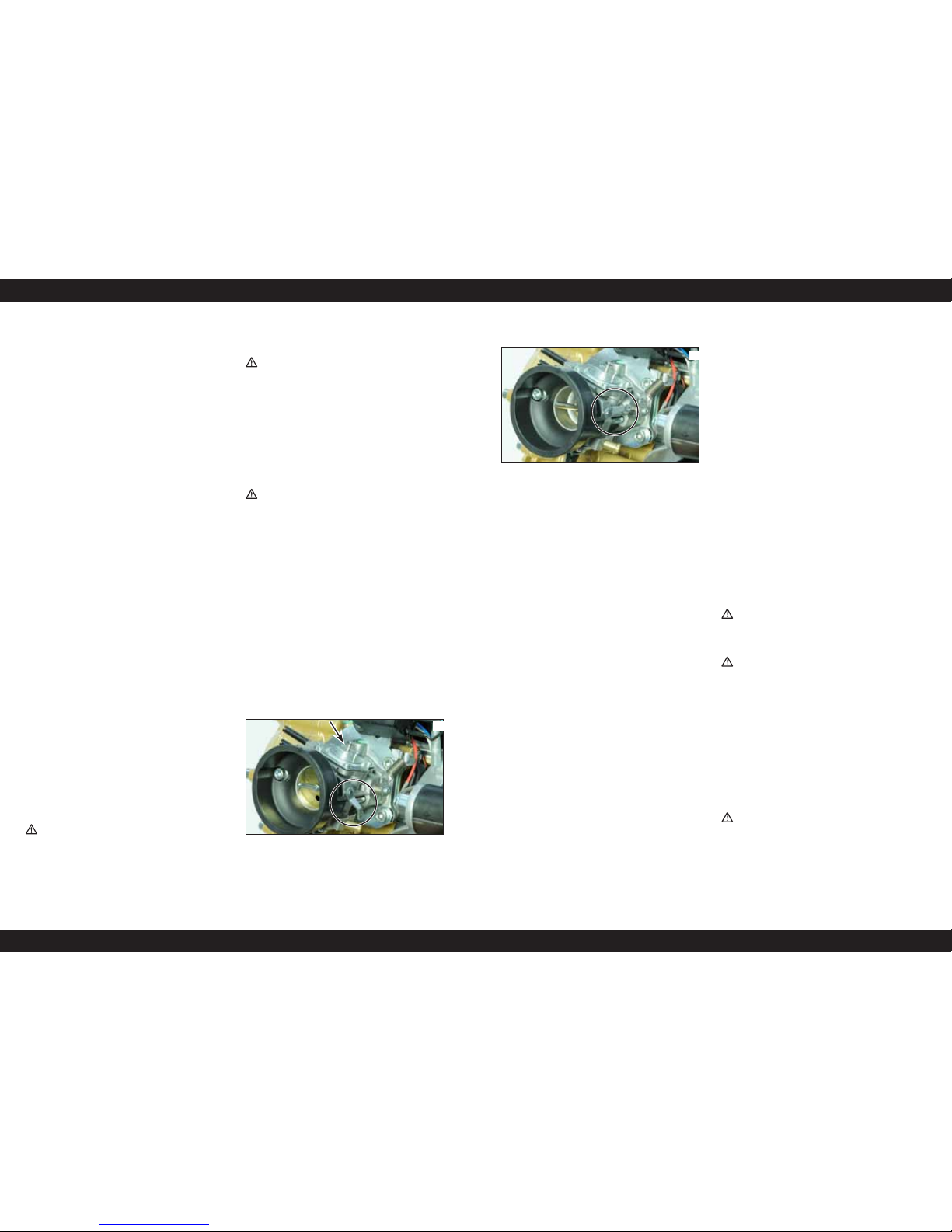
First cold starting: fill in the fuel system using the pump provided
(carefully follow the instructions provided by the frame’s manufacturer to find out it and use it in the correct way). To make this
operation easier push softly with a finger the diaphragm through
the hole indicated by the arrow in photo 1. Fill it in till the petrol
reaches the carburettor. At that moment immediately stop; if you
go on acting on the pump the petrol will leak causing the engine
flooding.
01
WALBRO WG8 CARBURETOR (THOR 100 engine only):
Move the starter level to the off position (photo 1); now hand the
starter and start pulling the rope till it grows hard. Pull with
strength without accelerating till the engine seems to start working (do not repeat this operation more than 3 times otherwise
the engine may flood). Now move the starter lever to the on
position (photo 2) and act on the starting rope without accelerating. If the engine doesn’t work with the first two attempts, try
again accelerating gently.
02
3.2 24/28 PWK CARBURETOR
Fill in the fuel system till the petrol reaches the carburetor hole
and then pump up three times (using the pump provided- Code
316.0016) to fill out the bowl. To start the engine pull upwards
the black level placed in the upper side of the carburettor.
Work the starter without accelerating till the engine start. Once it
works switch it off, disconnect the starter and start the engine
again slightly accelerating. For your safety only start the engine
after your harness has been COMPLETELY fixed!
3.3 THOR 200 ENGINE STARTING WITH ELECTRIC
STARTER
According to the carburettor model (Pwk or Walbro WB37) refer
to section 3.1 and 3.2 to fill in the fuel system. For the model
with electric starter the Polini throttle system has 3 buttons on the
bottom part of the throttle device. To start both the engines push
the black buttons together and slightly accelerate. For your safety
only proceed with this operation after your harness has been
COMPLETELY fixed!
ATTENTION: keep the switch in your hand during all the stages
and be ready to work it in case of any anomaly. If necessary
keep it pressed till the engine has completely stopped.
Once the engine starts we suggest testing the right functioning of
the kill switch button. After having checked it, start the engine
again without accelerating and without using the starter. Now
start the engine and leave it idle until it warms up to normal
temperature.
4- RUNNING IN
Run your engine in as instructed below to ensure that the engine
and transmission bed in correctly and to ensure continuous reliability in future. Once the engine starts, leave it idle until it warms
up to normal temperature. We suggest running the engine 15
minutes at medium-low engine power output gently accelerating
and with different intensity. Now we suggest checking the correct
idling calibration.
During the first flights or for the first 20 litres of petrol we suggest not keeping the engine at the maximum rpm for too much
time, considering that the 2-stroke engine doesn’t stand to the
constant rpm even if of medium power. We suggest varying the
engine rpm. Check the carburetion after the first landing (section
6). Repeat the running in every time you change one of the following parts: piston, rings, cylinder, crankshaft or main bearings.
5- ENGINE SWITCING OFF
Switch the engine off by pressing the button till the complete stop
(see the frame manufacturer’s instructions to find the button
position)
6- CARBURETION CHECK
For a complete carburetion check switch the engine off after
having worked it for some minutes under load. Remove the
spark plug; unscrew it by using the proper key and verify that
the porcelain colour is light-brown. On the contrary, ask to an
authorized dealer for the calibration.
7- CLEANING
Clean the engine when it is switched off and cold to avoid burns.
Clean the engine with a soft cloth soaked with neutral cleansing
and non-aggressive.
WARNING: Do not use acids that may damage the engine.
8-CARRIAGE
ATTENTION: Carry the engine only when cold. Follow the
frame manufacturer’s instructions for its carriage. Be careful of
the petrol during the carriage; its leaking may cause a fire.
8.1 CARRIAGE OF THE ENGINE WITH PWK
CARBURETOR
PWK carburetor has a breather pipe studied to carry the engine
when lying. To empty the carburettor unscrew half turn the breather brass nut (highlighted in photo 3 with an arrow) and wait till
the fuel enters the tank. Close the brass connection again. Now
the carburettor is empty and you can lay the engine ready to be
carry.
ATTENTION: never unscrew more than half a turn the bre-
ather nut to avoid damaging the OR seal. Never close too hard.

03
9- ORDINARY SERVICING
ATTENTION: THE SERVICING OPERATIONS MUST BE DONE
BY QUALIFIED PEOPLE ONLY. IF THE INSTRUCTIONS MENTIONED
BELOW WILL RESULT NOT CLEAR, WE SUGGEST ASKING FOR
SPECIALISTS BY POLINI MOTORI RETAILERS OR WHOLESALERS.
FOLLOW CAREFULLY WHAT DESCRIBED BELOW.
Maintenances and servicing necessary for the best set up of your
engine should be done regularly, or on all occasions before you
start flying. All the tasks and adjustments described below can be
done easily by following the instructions given in this manual.
Refer to your POLINI MOTORI dealer for scheduled services and
repairs, and insist that only original spare parts are used to
replace worn or broken components. Refer to the servicing tables
in sections 12 below for the frequency with which the various servicing operations must be performed.
9.1- REMOVE AND CLEAN THE AIR FILTER
Dirty air filter is one of the most common causes of poor engine
performance.
Clean the filter periodically or change it. Remove the filter loosening the clamps, unscrew the 4 screws using a cross screwdriver,
remove the filter cover and then the filter. Wash the filtering
material with water and mild soap,
After rinsing and wringing the filter, moisten it with oil for filters.
Clean filter box inside using a cloth and check the presence of
foreign bodies. Now reassemble all the parts being careful to
place correctly the 4 bars that maintain the filter in its position
and screw the 4 screws again. Wash the filter for maximum 2-3
times, then replace it.
WARNING. If the filter becomes clogged with fine dust as
well as normal dirt, replace it with a new one.
WARNING. Dirty air filters choke the engine and cause poor
performance. Torn or broken filters can allow dirt to enter the
engine and cause rapid deterioration of the piston rings, piston
and barrel.
9.2- CHECKING OF THE GEAR OIL LEVEL
Operate when the engine is cold. Maintain the engine in vertical
position and remove the oil level screw on the transmission
crankcase. (photo 4). Check that the oil level reaches the lower
edge of the level hole. If there is too much oil, let it flow out
from the level hole until it stops flowing and collect the oil in a
suitable container. If there is not enough oil, top up as required
through the breather hole located at the top. After checking it,
tighten the screws. Use ELF Moto Gear Oil 10 W 40 ANTI Clutch
Slippage or Shell advance gear SAE 10 W 40 API GL-3
04
OIL LEVEL
A
9.3 GEAR OIL REPLACEMENT
Change the oil when the engine is cold. Unscrew the screw on the
lower side of the clutch/gear group. Collect the oil flowing out in
a suitable container. Wait till the oil has completely flown out
and, if necessary, tilt the engine to the side to make this operation easier. Tighten the screws. Unscrew the breather pipe in the
top side of the crankcase and fill it out with:
(FOR THOR 100 ENGINE) 25cc of ELF MOTO GEAR OIL 10 W 40
ANTI CLUTCH SLIPPAGE. Place the connection/breather again.
(FOR THOR 200 ENGINE) 100cc of ELF MOTO GEAR OIL 10 W 40
ANTI CLUTCH SLIPPAGE. Place the connection/breather again.
Another option is: Shell Advance Gear SAE 10 W 40 API GL-3
WARNING: Do not throw spent oil into the environment. Dispose
of it correctly through authorised collection points.
9.4-STARTER ROPE REPLACEMENT
Remove the starter from the engine unscrewing the 4 screws
(Photo 5).
Remove the handle rope. Be careful since the central wheel will
turn till the complete spring discharge: keep it and discharge it
slowly to avoid damages or possible injuries. Remove the central
screw and its cover (photo 5.1).
Attention! Under the cover there are two teeth for the starter
jaw (check their condition and if worn replace them); under them
2 small callipers. Be very careful not to lose these small parts.
Prepare the new rope and tie a knot at the top. Remove the plastic wheel and the old rope.
05
5.1
Thread the new rope in its hole (photo 6), wind the rope on the
wheel (according to the entrance sense of the rope on the wheel)
(Photo 7). Now insert the plastic wheel in its housing again, the
spring, the teeth for the starter jaw and screw the cover again.
Now go on by charging the return spring: take the head of the
rope leaving 5-7 cm coming out the hole with “u” shape on the
wheel side. Turn the wheel three times in anti clock wise sense till
it stops in front of the exit hole on the aluminium case. Keeping
the plastic wheel stopped make the rope go through the case
hole. Insert the handle and the washer and tie a single knot as
shown in photo 8.
Reassemble the starter in the engine and screw the 4 M5 screws
with strength (see the tightening torque values table).
06
07
08
9.5- WALBRO WG8 AND WB37 CARBURETOR
DIAPHRAGM CHANGING
Remove the filter unscrewing the clamp by using a cross screwdriver. After removing the accelerator cable from the carburettor,
the supplementary spring, the carburettor pipe and the diffusion
pipe unscrew the two socket head screws and remove the carburettor from the engine. Now place the parts on a flat plane.
Remove the upper cover by unscrewing the 4 screws , remove the
diaphragm and the gasket, check that the inside part is clean and
reassemble by using the new diaphragm and the new gasket
(photo 09).
09
ATTENTION: The carburettor is made of many small and
fragile parts. Be very careful during all the phases with particular
attention to the idling and its springs; they both must not be touched.

Remove the lower cover by unscrewing the 4 screws (Photo 10),
remove the diaphragm and the gasket, check that the inside part
is clean in particular the metallic filter provided on the Walbro
WG8 model only (Photo 11) and assemble it again using the new
diaphragm and the new gasket. Reassemble the carburettor following the instructions in the opposite way, being very careful to
place the gaskets in the right places.
10
11
10- HOW TO BEHAVE IN FLIGHT
Maximum acceleration is recommended only to take off (full
power) or when really necessary!
In order to avoid a poor mixture from acceleration/ascension to
level flight conditions, loosen the engine till a descending phase
and then gradually accelerate again till achieving a level flight
or a glide angle or a rise angle wished. In this way you will be
sure to maintain firm and efficient the carburation, avoiding to
be over rpm with a minimum valve/throttle opening.
Two stroke engines do not stand constant range for a long time
too much. Take care of your engine by varying now and then the
rpm range. In this way the engine will have constant performance and a good elasticity improving its working during the time.
10.1 TEMPERATURE THERESHOLDS
Your 100/200 Thor engine, according to the pilot weight and
wind size, must have a flight temperature between 230° and
250° under sparkplug (these measures have been taken with
Polini thermocouple tool – 928.830.002). This parameters may
vary according to different factors: environment temperature,
working height, wet, quality of the fuel used, anyway this temperature has not to exceed 265°/280 for short period.
Furthermore it is important to say that carbon deposits caused by
a richer mixture may limit during the time the exceeding loss of
heat, favouring high temperatures that can compromise the reliability of the engine. For these reasons we remind you to follow
very carefully the section concerning the servicing.
11- ENGINE FITTING ON THE FRAME
The engine is supplied in a packaging and it is screwed on a cage
to protect it during its carriage. Unscrew the 4 M8 screws that fix
it and extract the engine. KEEP THE PACKAGING AND ITS CAGE
FOR POSSIBLE REPARATIONS UNDER WARRANTY. WARRANTY IS
NOT ACCEPTED IF THE ENGINE IS NOT SHIPPED IN THE ORIGINAL
PACKAGING. The engine must be fixed on the frame using the 4
clamps with the silent-block and positioning some spacers (on
the Thor 100 only) if the frame doesn’t have the necessary space
to fit the manual starter. Refer to the drawing for the engine
fixing measures.
ATTENTION: The engine must be positioned as indicated in
the picture. To assure a perfect lubrication, do not rotate it.
Because of the overall dimensions during the carriage the filter is
180° rotated. Do not unscrew the clamp to rotate it to reach the
original position. The filter has a hole at the top to be used to
avoid its rotation when using. Place the clamp or a small cable
(they are not provided with the engine) fixing them in a proper
zone of the frame.
ATTENTION: the filter may rotate if you do not fix it and it
could collide with the propeller, breaking it. This may be very
dangerous for your safety.
11.1 FUEL SYSTEM
Prearrange the frame with a proper tank and its pump to make
the fuel reach the carburettor. Connect the fuel pipe to the manifold on the carburettor, fix it using a clamp and verify that there
is not air coming in.
11.2 ACCELERATOR
Fix the carburettor by using the proper accelerator support (not
supplied). After assembling the accelerator, check that its travel is
enough to reach the carburettor throttle valve opening and check
that recovery is good in order to avoid the engine staying accelerated. Check the presence and the right supplementary spring
installation (photo 12) provided with the Thor 100 with Walbro
carburettor only. Connect the electrical wires of the throttle, one
on the mass wire of the coil and the other on the + of the coil
(female connector)
12
11.3 SPARK PLUG
Remove the spark plug and check that the gap between the
spark plug electrodes is 0,9mm. Fit the spark plug hood inside
the conveyor cap being careful to fit it completely. Now engage
on the spark plug and enter the small rubber inside the hole in
the plastic conveyor (photo 13). Spark plug type: NGK BR10EG
13
11.4 PROPELLER
Use propellers by Polini Motori, both for Thor 100 and 200 . The
use of a not proper propeller may compromise the engine working.
11.5 HOW TO CONNECT THE VOLTAGE REGULATOR
(OPTIONAL)
Connect the voltage regulator to the connector. Connect the red
cable (E) to the positive pole on a lead battery (photo 14).
WARNING. Use lead batteries only. The usage of other kind
of batteries could provoke explosions or bursts.
Connect the negative pole of the battery to earth on the engine.
During its working the voltage regulator, if connected in the right
way, will give a 14,5 Vdc voltage on the battery.
14
OPTIONAL
A
B
E
C
D

12- SERVICING TABLE
At every use Check the bolts and screws tightening
Check the silent-block conditions
After the first 10 hours Change the gear oil level
Check carburation
Check the spark plug electrode distance
Every 25 hours Replace the spark plug
Clean the air filter
Replace the muffler springs
Every 50 hours Change the gear oil
Replace the silencer deadening material
Every 100 hours or every year Replace the air filter
Replace the starter rope
Replace the diaphragm and clean it
Replace the silent-block
Replace the fuel system pipes
Replace the reed valves
Every 100 hours Check the piston and piston rings
Replace the pin and rollers cage
Decarbonise and clean the decompression hole
Disassemble the reduction gear and check the clutch and bell wear
Every 200 hours Replace the piston and piston rings
Replace the reed valve
Every 400 hours Replace all the bearings and seals
Replace the crankshaft
100 200
TIGHTENING TORQUE VALUE FOR ENGINE BOLTS AND
SCREWS
M N.m Kgf.m Lbf.ft
Locking
compound
•
HEAD NUTS THOR 100 7 14 1,4 10,3
•
HEAD NUTS THOR 200 6 14 1,4 10,3
•
HEAD NUTS THOR 200 8 22 2,2 16,2
•
CRANKSHAFT NUT - CLUTCH SIDE 12 60 6 44,4
• •
CRANKSHAFT NUT - IGNITION SIDE 10 40 4 29,5
• •
PROPELLER CENTRAL SCREW 10 40 4 29,5 LOCTITE 243
• •
SPARK PLUG 20 2 14,8
•
COUNTERSHFAT THOR 200 12 60 6 44
•
CLUTCH NUT THOR 200 20 80 8 59
• •
CRANKCASE SCREWS 6 8 0,8 5,9
• •
CARBURATOR LOCKING SCREWS 6 8 0,8 5,9
• •
INTAKE MANIFOLD LOCKING SCREWS 6 8 0,8 5,9
• •
MUFFLER STUDS NUTS 6 10 1 7,4 LOCTITE 270
• •
SILENCER LOCKING SCREWS 8 15 1,5 11,1 LOCTITE 243
• •
MUFFLER LOCKING SCREWS 8 15 1,5 11,1 LOCTITE 243
STANDARD TIGHTENING TORQUE VALUES N.m Kgf.m Lbf.ft
5mm Bolts and nuts 6 0,6 4,44
6mm Bolts and nuts 10 1 7,40
8mm Bolts and nuts 25 2,5 18,50
10mm Bolts and nuts 45 4,5 33,30
12mm Bolts and nuts 55 5,5 40,70
13- PROBLEMS DIAGNOSTIC REASON REMEDY
The engine doesn't start Out of petrol Add petrol
Petrol doesn't reach the carburetor Check the fuel system circuit
Old or wrong petrol Empty the tank and the fuel system circuit and replace the petrol.
Flooded engine
Remove the spark plug, start the engine, dry or replace the
spark plug.
Defective spark plug Replace it
Blackened spark plug or wet Clean and dry the spark plug or replace it
Earthened switching off cable Check the wiring
Spark plug hood Check it
Carburetor has problems Clean and check it; eventually replace the diaphragm
No spark Check the ignition, coil and wiring
The engine doesn't idle Dirty carburetor Calibrate the carburetor
Out-of-adjustment screws Clean and check it; eventually replace the diaphragm
Defective spark plug Replace it
The engine doesn't reach the maximum rpm
Wrong carburetion Calibrate the carburetor
The carburetor has problems Clean and check it; eventually replace the diaphragm
The reed valve has problems Replace the reeds or the whole reed valve
Dirty air filter Clean or replace it
Dirty exhaust system Clean or replace the deadening material
Engine revved up when idling Out-of-adjustment screws Calibrate the carburetor
Air through the gaskets Replace the gaskets and seals
 Loading...