

Page 1

ALARMING DEVICE
FOR DETECTION OF GAMMA RADIATION
AND CHEMICAL WEAPONS VAPORS PM2010
OPERATING MANUAL
Page 2

2
CONTENTS
1 INTRODUCTION ……………………………………………………………………….3
2 DESCRIPTION AND OPERATION OF THE DEVICE ......................................... 4
2.1 Application of the device ................................................................................... 4
2.2 Delivery kit......................................................................................................... 5
2.3 Specifications .................................................................................................... 6
2.4 Design and theory of operation ................................ ................................ ......... 8
3 USE OF THE DEVICE ......................................................................................... 13
3.1 Preparation for use ............................................................................................ 13
3.2 Device operation .............................................................................................. 14
4 MAINTENANCE ................................................................................................... 16
5 TROUBLESHOOTING ......................................................................................... 19
6 STORAGE AND SHIPPING................................................................................. 20
7 UTILIZATION ...................................................................................................... 21
8 WARRANTY ........................................................................................................ 22
9 PACKING CERTIFICATE .................................................................................... 23
10 CERTIFICATE OF PUTTING INTO SERVICE................................................... 24
11 ACCEPTANCE CERTIFICATE .......................................................................... 25
12 WARRANTY CERTIFICATE ................................ ................................ .............. 26
13 CLAIMS ............................................................................................................. 27
APPENDIX A Copy of certificate toxic substance detection module (tsm) ...................... 28
APPENDIX B Beta radiation source, copy of passport ................................................. 29
Page 3

3
1 INTRODUCTION
The present Operating Manual is intended to describe the design and operation of the
alarming device for detection of gamma radiation and chemical weapons vapors PM2010
(hereinafter referred to as device). The Operating Manual includes general description of the
device, specifications, operation instructions, instructions for its maintenance, as well as some
other information necessary for the proper operation of the device and full realization of its
possibilities.
The name of the device in the documentation is written as follows: “Alarming device
for detection of gamma radiation and chemical weapons vapors PM2010
Type 100345122.042-2004”.
During manufacturing of the device some changes may be introduced in its electrical
scheme, construction, appearance and software that do not influence the specifications and
metrological parameters and, therefore, may be not specified in this manual.
Page 4

4
2 DESCRIPTION AND OPERATION OF THE DEVICE
2.1 Application of the device
2.1.1 The device is designed for
- alarming about exceeding a set threshold of the ambient dose equivalent rate
Н
(10) of
photon radiation (DER) relative to set threshold;
- alarming about exceeding vapor concentration in air of toxic substances -
organophosphorus substances (sarin, soman, V-gases) and arsenic-containing substances
(lewisite) relative to the threshold of toxic substances vapors concentration.
The device operation history is stored in its non-volatile memory and can be transferred
to a personal computer (PC) via an infrared (IR) interface of data transmission using IrDA
interface.
The device may be operated both indoor and outdoor by a wide range users involved in
detecting of ionizing radiation sources and vapors of toxic substances.
The device may be used by staff of emergency services, by border guards, customs
officers and other services.
2.1.2 The device is to be used under environmental conditions as follows:
- temperature from -10 oC to + 50 oC;
- relative humidity at +25 oC
and lower temperature up to 98 %;
- atmospheric pressure from 84 kPa to 106.7 kPa;
- air dust content, no more than 0.2 mg/l.
Page 5

5
2.2 Delivery kit
2.2.1 The delivery kit of the alarming device is presented in the Table 1.
Table 1
Item
Quantity Note
Alarming device for detecting of gamma
radiation and chemical weapons vapors
PM2010
1 piece
Operating manual
1 piece
Case
1 piece
CD with software
1 piece
Passport of radioactive source
1 piece
included in operating
manual, Appendix B
Certificate of toxic substance module
1 piece
included in operating
manual, Appendix A
Battery Energizer L91BP – 2 AA
1)
2 pieces
IR adapter (ACT-IR220L or IR-210B)
2)
1 piece
Set of spare parts and tools (SET-O)
Filter
1 piece
Rod
1 piece
Screwdriver
1 piece
Filtering tissue element
4 pieces
Filtering element
4 pieces
Bottle with filter filler
1 piece
Coarse calico strip
0.4 m
Imitator
2)
1 piece
Rotameter
2)
1 piece
1)
other batteries with similar parameters may be used;
2)
available as option upon request
Page 6

6
2.3 Specifications
2.3.1
Modes of operation
- test mode;
- calibration mode;
- mode of detection of exceeding the set
thresholds of gamma radiation and
concentrations of toxic substance vapors;
- mode of communication with PC
2.3.2
Range of the DER threshold
from 0.001 to 999 mSv/h
2.3.3
Step of threshold setting
1 Sv/h
2.3.4
Main relative error of a comparison of a
registered DER value at
137
Cs radiation
with the set DER threshold value
(30+K/
Н
) %,
where
Н
– DER value, mSv/h,
K – coefficient equal 0.01 mSv/h
2.3.5
Gamma radiation energy range
from 0.06 to 3.0 MeV
2.3.6
Energy response relative to
137
Cs, no
more
30 %
2.3.7
Time of the device response in case of a
step DER increase from a value of
10 Sv/h to a value of no less than
100 Sv/h, no more than
10 s
2.3.8
The device should produce audio and
visual signals in case when the set
thresholds are exceeded and record in
non-violate memory the events of set
DER threshold exceeding and history of
DER registration in case of supply
voltage changes
from 2.5 to 3.2 V
2.3.9
Threshold of detection (with a toxic
substance module) at contents higher
than threshold values at normal climatic
conditions (NCC): temperature 205 oC;
atmospheric pressure 101.3(+5.4;
-17,3) kPa; relative humidity 60(+20;
-30) % should be no more than
- vapors of toxic organophosphorus
substances (sarin, soman, V-gases)
- arsenic-containing substance (lewisite)
510-5 mg/l for 15 s
210-4 mg/l for 5 s
2.3.10
Variation of the threshold of detection
(with a toxic substance module) at limit
temperature values compared to the
threshold value at NCC, no more than
-50 %
2.3.11
Variation of the threshold of detection
(with a toxic substance module) at
relative air humidity (98 % at 25 oC and
lower) compared to the threshold value
at NCC, no more than
-400 %
2.3.12
Residual effect of a toxic substance
module at operation temperature range,
no more than
30 s
Page 7

7
2.3.13
Instability of comparison of registered
DER value with threshold value for 24 h
of continuous operation no more than
5 %
2.3.14
Device should not produce visual and
audible alarm when substances as
follow are present in air:
- gasoline at vapor concentration no
more than
- diesel fuel (used both in summer and
winter) at vapor concentration no more
than
- exhausts of isolated internalcombustion engines (gasoline or diesel)
at distance to exhaust tube more than
1.5 mg/l
0.5 mg/l
15 m
2.3.15
Battery lifetime at normal conditions and
audio alarm sounding no more than
5 min/24 h
40 h
2.3.16
Device is resistant to
- temperature of ambient air from -10 to
+50 oC;
- relative air humidity up to 98 % at 25 oC;
- atmospheric pressure from 84 to 106.7 kPa
2.3.17
Device is resistant to
- sinusoidal vibration in a frequency range
of 5 – 35 Hz and a bias amplitude for
frequencies lower than the transition
frequency 0.75 mm;
- repeated shocks with acceleration of
100 m/s2, duration of shock pulse of
2-50 ms, at shock rate of 60-180 shocks per
minute
2.3.18
Device is resistant to RF electrical and
magnetic fields (under IEC 61000-4-3:1995):
- in the frequency range of 80 to 1000 MHz
- in the frequency range of 800 to 960 MHz
and of 1.4 to 2.0 GHz (generated by digital
mobile phones)
10 V/m (severity degree 3)
30 V/m (severity degree 4)
2.3.19
Device is resistant to electrostatic
discharges (under IEC 61000-4-2:1995)
8 kV
2.3.20
Device in a transportation case is proof
against
- temperature from -20 up to +50 oC;
- humidity up to 100 % at 35 oC;
- shocks with an acceleration of 147 m/s2, a
duration of 10 ms;
- vibrations with a frequency of 5-35 Hz and
a bias amplitude 0.75 mm
2.3.21
Protection degree of the case
IP31
2.3.22
Device weight, no more
no more 0,55 kg
2.3.23
Device weight in a case, no more
no more 1,2 kg
2.3.24
Device dimensions, no more
no more 60х35х230 mm
2.3.25
Reliability parameters:
- average time to first failure
no less than 20 000 h
- average service life
no less than 10 years
- average time of recovery
no more than 120 min
Page 8

8
2.4 Design and theory of operation
2.4.1 The device consists of two independent modules:
- gamma radiation detection module (GMM);
- toxic substance vapor detection module (TSM).
The dose equivalent rate is registered in the mode of detection of exceeding the set
thresholds of gamma radiation using GMM based on the Geiger-Muller counter.
Exceeding of air concentrations of toxic substances vapors relative to set threshold level
is detected by using a TSM based on an ionizing chamber with 63Ni beta-source. An analyzed
air is pumped through the chamber using a micropump.
The principle of the device operation is based on comparison of the registered DER value
with the set DER threshold and the registered concentration value of toxic substance vapors
with the set threshold value of concentration level.
The detection modules are operated by a microprocessor controller with a built-in
analogue-digital converter (ADC).
The device is powered by two AA batteries. The nominal battery voltage is 1.5 V.
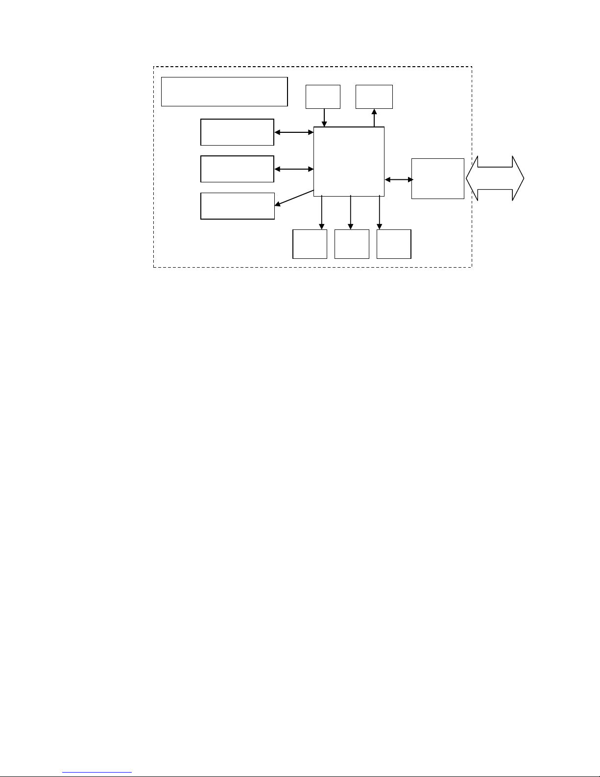
2.4.2 A block diagram of the device is presented in Figure 1.
The device consists of:
- gamma radiation detection module (GMM);
- toxic substance vapor detection module (TSM);
- microprocessor controller (MPC);
- audio alarm device (AAD);
- red light-emitting diode (R-LED) for alarming about exceeding a threshold of the toxic
substance vapor concentration;
- yellow light-emitting diode (Y-LED) for alarming about exceeding a threshold of the
gamma radiation DER;
- green light-emitting diode (G-LED) for indicating the device ON and the battery voltage;
- infrared interface (IRI);
- ON/OFF button (BN);
- batteries;
- micropump (MP).
Page 9
9
Figure 1 – Block diagram of the device
The device operation algorithm provides for a continuous measurement, statistical
processing of measurement results, fast adaptation to variations of the radiation intensity (a
time of measurement is inversely dependent on the radiation intensity). An infrared interface
(IrDA) is used for an exchange of information between MPC and PC.
The device is equipped with a non-volatile memory used to accumulate and store
information.
2.4.3 Design of the device
2.4.3.1 The device is designed as a monoblock consisting of a toxic substances module
(TSM), a Geiger-Muller module (GMM), a printed circuit board of a microprocessor controller
(MPC) and a housing involving an audio alarming device (AAD) and batteries. The input
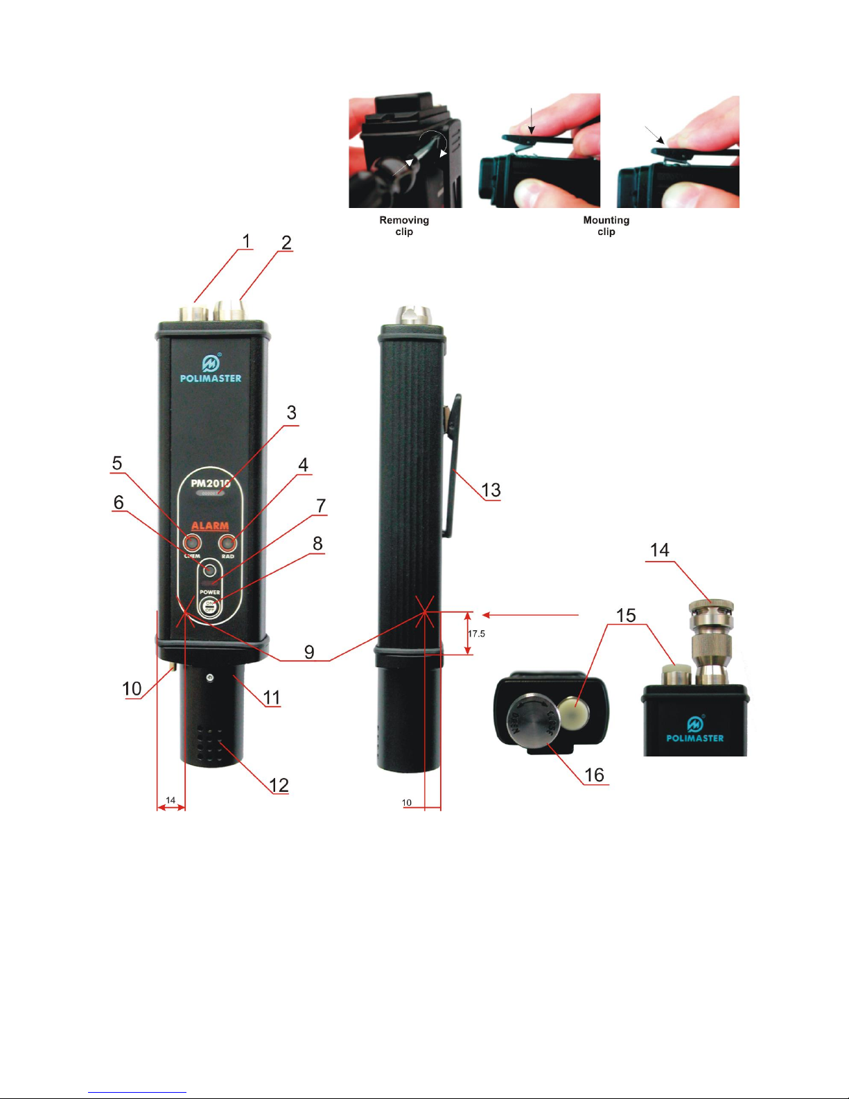
connecting pipe 2 of TSM (Figure 2) with a cap 15 is located on the top cover of the device.
When the device is operated the cap is taken off the connecting pipe 2 and fixed adjacent to the
connecting pipe at a plug 1. During the device calibration, the filter 14 involved in the set of
spare parts and tools (SET-O) is screwed on the connecting pipe 2. The Red-LED 4, YellowLED 5, Green-LED 6 , ON/OFF button 8, window 7 of the IR interface and device serial number
3 are located on the front panel of the device.
The clip 13 is placed on the back side of the device. The Figure 2 shows how to mount
and remove the clip.
The Geiger-Muller module (GMM) is located in the bottom part of the device. The
housing 11 involving batteries and the audio alarming device (AAD) 12, as well as the cap 10 of
the output connecting pipe are fixed to the lower cover of the device.
The GMM effective center 9 is shown in Figure 2, and an arrow points a direction of
calibration.
MPC
AAD
IRI
GMM
TSM
IrD
R-LED
G-LED
Y-LED
BN
IrDA
PM2010
MP
Page 10
10
1 – plug for fixing the cap of the input connecting pipe of TSM; 2 – input connecting pipe of
TSM; 3 – window with the device serial number; 4 – Yellow-LED; 5 –Red-LED; 6 – Green-LED;
7 – input window of the IR interface; 8 – ON/OFF button; 9 – GMM geometric center; 10 – cap
of the output connecting pipe; 11 – housing with batteries; 12 – window for the audio alarming
device; 13 – clip; 14 – filter, 15 – cap; 16 – filter cover
Figure 2
Page 11

11
2.4.4 Modes of operation of the device:
- test mode;
- calibration mode;
- mode of detection of exceeding the set thresholds of gamma radiation and
concentrations of toxic substance vapors;
- mode of communication with PC.
In any operation mode the device controls over the battery voltage (see clause 3.2.5).
2.4.4.1 Test mode
The device enters this mode every time when it is turned ON or the batteries were
replaced. While in this mode the microprocessor controller provides for testing and diagnostics
of the main device modules. If all tests are passed successfully.
2.4.4.2 Calibration mode
The device enters this mode the batteries were replaced.
While in this mode, the device performs the calibration of the TSM channel (blow through
the ionization chamber, autocalibration of "zero" of the TSM channel). After calibration is
completed, the device automatically goes into the mode of detection of exceeding the preset
thresholds of gamma radiation and concentrations of toxic substance vapors.
2.4.4.3 Mode of detection of exceeding the preset thresholds of gamma radiation and
concentrations of toxic substance vapors.
While in this mode the device performs a continuous and independent control of the
radiation and chemical conditions.
While in this mode the device produces light and audible signals as follows:
- "Chemical alarm" (Red-LED is flashing) when the threshold value of the TSM is
exceeded;
- "Radiation alarm" (Yellow-LED is flashing) when the preset DER threshold is exceeded.
The light alarms are accompanied by audible alarms if these are enabled in the mode of
communication with PC.
The device provides for a possibility to record and store the history of operation (DER
values with set time intervals, alarms, i.e. exceeding of the set threshold value of DER and
concentration of TSM), and values of preset parameters in the non-volatile memory.
2.4.4.4 Mode of communication with PC
The device performs an exchange of information with PC using OS WINDOWS through
the infrared channel. An IR adapter and an exchange protocol compatible with the IrDA
interface are used.
While in the mode of communication with PC the following operations may be performed:
- the device can be registered to a specific user;
- to store a time when the device was received and returned by user;
- to read information from the device memory;
- to change the following device parameters:
the set DER threshold;
to disable audio alarms;
the time interval to store the history of operation;
- to store and transmit to PC the history of the measurement of the photon radiation DER,
records about exceeding the preset thresholds of gamma radiation and concentrations of toxic
substance vapors.
Page 12

12
2.4.5 Marking and sealing
The logo and name of the manufacturer, name of the device, IP code, and the device
serial number are inscribed on the device. The "Radiation danger" sign with the source type and
its activity is marked on the bottom side of the device housing.
A seal that prevents an unauthorized opening of the device is placed in the faceplate of
the device in the screw groove.
2.4.6 Packing
The device is put into a pasteboard box together with its documents and SET.
Page 13

13
3 USE OF THE DEVICE
3.1 Preparation for use
3.1.1 General information
3.1.1.1 When buying the device please check the delivery kit according to clause 2.2.1
and perform the device operation check up according to clause 3.1.4.
The device should not be subjected to severe mechanical shocks, any strong chemicals
and solvents and open fire sources.
3.1.2 Safety precautions
3.1.2.1 During the device assembling, calibration, repair and maintenance when
radioactive sources are used, all the requirements and regulations ensuring the radiation and
sanitary safety should be observed.
3.1.2.2 The beta radiation source IBIRRZN-63-IIa, 7016-056-41805307-2002 which is
included in the ionization chamber contains the 63Ni radionuclide of 0.6 GBq activity. This
source is located inside of the ionizing chamber in the device housing.
3.1.2.3 The beta radiation DER does not exceed the natural background level at any
point of the outer surface of the package with the device inside. The device design excludes the
possibility of the access to the source during device operation. Therefore it is not necessary to
take any additional safety precautions actions for radiation security.
3.1.3 Preparation for operation
3.1.3.1 Before using the device, please read this operating manual carefully.
3.1.3.2 Take the device from the package.
3.1.3.3 Insert the batteries into the battery compartment 11 (Figure 2).
3.1.3.4 Remove cap 15 from the connecting pipe of the ionizing chamber 2 and the
output connecting pipe 10.
3.1.3.5 Screw cap 15 on the connecting pipe at a plug 1, and put cap 10 of the output
connecting pipe into SET-O.
3.1.3.6 When starting the operation after the long storage of the device, it is required to clean
the gas system and the ionizing chamber in according to clause 4.4 of the present Manual.
3.1.3.7 Calibrate the device according to clause 3.2.1.2. After calibration completion the
device is ready for operation
3.1.4 The device operation checking
3.1.4.1 After device calibration according to clause 3.2.1 it is necessary to check up the
device operation. After calibration completion, the Green-LED should light constantly and a
sound of the working micropump should be heard.
To check up the chemical channel operation, bring the imitator from the SET-O (set of
the spare parts and tools) to the input of the ionizing chamber. The light alarm (Red-LED)
should flash and audio alarm will be heard. Remove the imitator. The light and audio alarms will
be switched OFF in no more than 30 s.
Caution! When checking up the chemical channel operation with the imitator from
the SET-O in enclosed space it is necessary to provide the blowout from the output
connecting pipe outdoors (exhaust ventilation). Before the iterative checking up it is
necessary to blow out the gas system through the TSM filter for 10-20 minutes
To check up the radiation channel, bring a radioactive source (its energy range is from
0.06 to 3.0 MeV) close to the GMM geometrical center 13 (Figure 2). The light alarm (YellowLED) will flash and audio alarm will be heard. Remove the source. The light and audio alarms
will be switched OFF for no more than 30 s.
To turn the device OFF, press the button 8. The Green-LED 6 and the micropump should
be switched OFF.
Page 14

14
3.2 Device operation
3.2.1 Turning on the device turn, testing and calibration
3.2.1.1 To turn the device ON, press the ON/OFF button 8 (Figure 2). The device enters the
test mode after it is turned ON or after the batteries are replaced. While the device is in this mode,
Red-LED and Yellow-LED are flashing in turn. After completion of the test mode the device can go
either to the calibration mode (if batteries were replaced), or to the mode of detection of exceeding
the preset thresholds. The device is ready for operation, when Red-LED and Yellow-LED are
switched OFF and Green-LED is switched ON.
3.2.1.2 While in the calibration mode, Red-LED and Yellow-LED are flashing
simultaneously. The calibration of TSM is performed in this mode. To calibrate the TSM, mount
the filter 14 (Figure 2) (included in SET-O) to the input connecting pipe 2 and turn its cover 16 to
the “Open” position. After that enter the calibration mode by replacing the batteries. The
calibration will be completed in no more than 2 min. The calibration completion is indicated by
Red-LED and Yellow-LED switching OFF. After the calibration completion, turn the filter cover
16 to the “Close” position, remove the filter 14 and bring it into the right position in the SET-O.
The device automatically enters into the mode of detection of exceeding the preset thresholds
of the gamma radiation DER and concentrations of toxic substance vapors.
Caution! If the calibration process was interrupted (the device was turned OFF
before the simultaneous flashing of the Yellow-LED and the Red-LED stopped), then in
the mode of detection of exceeding of the set thresholds of gamma radiation and
concentrations of toxic substance vapors the Red-LED will be flashing with 10 s
intervals. In this case to ensure detection thresholds, perform calibration until both the
R-LED and the Y-LED are off.
3.2.2 Device operation in the mode of detection of exceeding the preset thresholds of the
gamma radiation DER and concentrations of toxic substances vapors
3.2.2.1 While in the mode of detection of exceeding the preset thresholds of the gamma
radiation DER and concentrations of toxic substances vapors, the device can be used for the
simultaneous detection of toxic substance vapors (TSV) in air and the detection and location of
gamma radiation sources (GRS).
The device operates with the parameter values set by the manufacturer (3.2.3.1). To use
other parameters, it is necessary to set the other values (3.2.4).
The device automatically enters the mode of detection of exceeding the preset thresholds
of GRS and TSV after the completion of the calibration mode.
3.2.2.2 Detection of GRS and TSV
To achieve the maximum sensitivity during the GRS detection, the device should be
placed in such a position that the calibration direction indicated in Figure 2 coincides with a
direction to a scanned object.
The detection efficiency is dependent on the proximity of the device to an examined
object (thing, car, person, etc) and velocity of its movement along the object.
To achieve the maximum sensitivity during the TSV detection, the input connecting pipe
of the toxic substance module should be completely opened.
3.2.2.3 Location of gamma radiation sources
When a gamma radiation source is detected, it can be located.
To locate the source, the device should be at no more than 10 cm distant from the
scanned object. The velocity of the device movements along the scanned object should not
exceed 1cm/s. As the device moves closer to the gamma radiation source, a rate at which
Yellow LED is flashing and audio tone is repeated will increase.
When the maximum rate of audio signals is achieved, a continuous audio tone is
produced. The source can not be located better.
Page 15

15
Note – The location of GRS is only possible in the only case when DER emitted by a
source at a distance of 10 cm is higher than 1 Sv/h, as the minimum settable threshold equals
to 1 Sv/h.
3.2.3 Parameters setting
3.2.3.1 The preset parameters
The device is shipped with the preset parameters as follows:
- time intervals for storage of current photon
radiation DER values in the device non-volatile memory 60 min
- threshold photon radiation DER value 1 Sv/h
- threshold for detection of vapors of
- organophosphorus substances (sarin, soman, V-gases, etc. ) 510-5 mg/l
- arsenic-containing substances (lewisite) 210-4 mg/l
- audio alarm device enabled
3.2.4 Device operation in the mode of communication with PC
3.2.4.1 The device is in the mode of communication with PC during 15 s after it is turned
ON. To repeat a communication, it is necessary to turn the device OFF and then to turn it ON
again.
To use the mode of communication with PC is possible only after the application program
supplied on CD is installed on PC.
An IR adapter and the application program PM2010 (supplied on CD) should be used to
operate with the device in the mode of communication with PC.
Minimum requirements to a computer and its software:
- Intel Pentium;
- 128 Mb RAM;
- Windows;
- 20 Mb free on the hard disk and an adequate space available to install the database;
- 800X600 resolution of a monitor;
- IrDA.
Connect the cable of the IR adapter to a communication port of the personal computer or
use the PC with a built-in IR adapter.
To install the application program, use the CD with software included in the delivery kit.
The Help file describes how to run the application program.
To communicate with PC, turn the device ON and place it for 15 s near the IR adapter at
a distance of 10-20 cm, the IR interface window should face the IR adapter. The information
exchange between the device and PC will be carried out in some seconds. The information
exchange mode is confirmed by periodic flashing (2 times per second) of the Yellow-LED and
Red-LED. Follow the instructions given in the application program for further activities.
3.2.5 Control over the battery voltage
3.2.5.1 In any mode of operation, the device continuously controls over the batteries
voltage, that is indicated by a solid light of Green-LED. If the batteries voltage drops below the
permissible level, Green-LED flashes. The batteries should be replaced. If the batteries are not
replaced, the device microprocessor switches OFF the micropump and the device will operate in
the only mode of detection of gamma radiation sources, and the TSM will not operate (GreenLED is flashing). If the batteries voltage drops even lower, the device will be turned OFF.
3.2.6 To turn the device OFF
3.2.6.1 To turn the device OFF, press the button 8 (Figure 2). The information exchange
mode is confirmed by periodic flashing (2 times per second) of the Yellow-LED and Red-LED.
Page 16

16
4 MAINTENANCE
4.1 General guidelines
4.1.1 The device maintenance is performed by specially trained personnel which have
finished the training and have the experience in maintenance.
4.1.2 The maintenance is to be carried out in due time to provide the device readiness for
operation and maximum service life.
4.1.3 The maintenance is carried out:
- when the device is delivered by the manufacturer;
- in the course of operation.
4.2 Safety measures during maintenance
4.2.1 The TSM module includes the beta radiation source. The TSM module design
ensures the operation safety of personnel without using special radiation shields. The radiation
background level on the device surface is within the natural background values.
WARNING! It is forbidden to disassemble the ionization chamber and to take out
the beta radiation sources without a special need.
4.2.2 After the beta radiation source service life, indicated in source passport (Appendix
B) is expired, it should be replaced by a new one. The radioactive source replacement should
be performed by the specially trained personnel of the manufacturer (personnel of A group).
4.2.3 The utilization of used sources should follow a determinate order observing the
requirements of handling radioactive materials.
4.3 Maintenance procedure
4.3.1 When the device is put into service, as well as during operation the scheduled
maintenance should be provided. A list of activities and the time intervals between their
fulfillment are given in the Table 2.
Table 2
List of activities
Time intervals between activities
1 Cleaning of gas systems and
ionizing chamber:
- detection of
organophosphorus
substances
- detection of arsenic –
containing substances
when the device is delivered by the manufacturer;
1 year;
1 year
2 Replacement of filtering
elements of filter 2.5 years
3 Replacement of radioactive
source
5 years
4 Decontamination of device
as needed, but at least once a year
Page 17

17
4.4 Cleaning of gas system and ionizing chamber
4.4.1 To clean the input connecting pipe of the TSM:
- turn the device OFF, put the device in an upright position, filter 14(Figure 2) up, take
the filter out;
- take the rod and a coarse calico strip, 8-10 mm wide, 10-15 mm long (from the
SET-O), pass the strip through the rod slot, moisten it with alcohol and squeeze to
remove drops;
- insert the rod into the TSM input connecting pipe to a depth of 25-30 mm and wipe
the rod hole with rotatory movements;
- renew the strip and repeat the procedure until the tissue is quite clean.
4.4.2 To clean the ionizing chamber:
- insert the rod with tissue moistened with alcohol into the ionizing chamber through the
cleaned input connecting pipe;
- wipe the chamber internal surface with rotatory movements.
Repeat the procedure 2-3 times renewing the tissue strip.
When the cleaning is completed the device should be held OFF without filter for one
hour.
4.4.3 To blow out the gas system, it is necessary to turn the device ON (the filter cover
open) and hold it ON for one hour. False “chemical alarms” may occur. After an hour turn the
device OFF and close the filter cover.
CAUTION! When the maintenance of the gas system and ionizing chamber is
performed, alcohol drops and tissue fibers should not be left in the ionizing chamber and
connecting pipe.
4.5 Replacement of the filtering elements of the TSM filter
4.5.1 Take out the filter 14 (Figure 2).
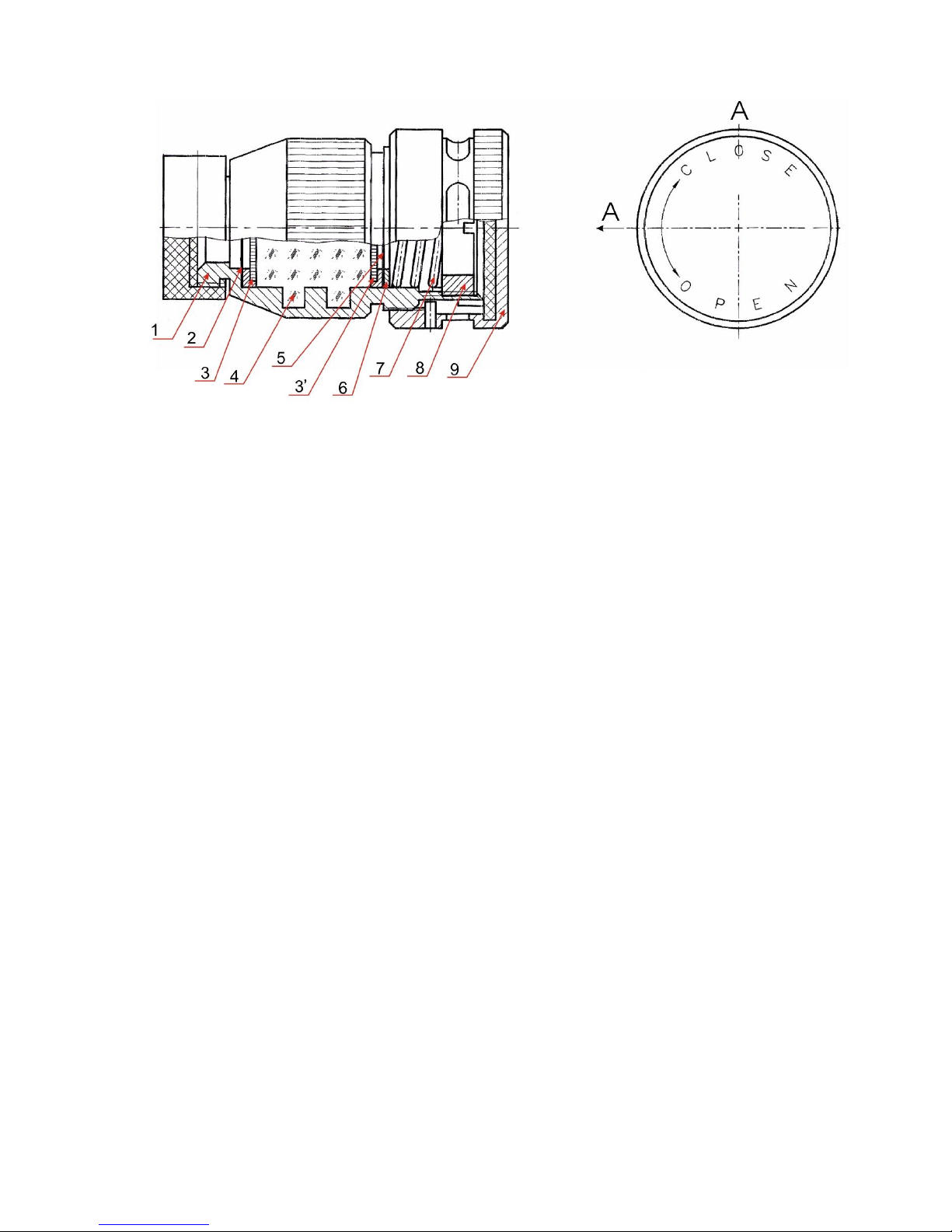
Figure 3 shows the filter structure. To replace the filtering elements of the TSM filter:
- open the cover 9;
- unscrew the nut 8 from the body 1 using a screwdriver (included in SET-O);
- take off spring 7, washer 6, filter 5 (replace the filter 5 by a new one from SET-O) and
gauze screen 3 (blow the screen out) from the body 1;
- remove carbon filler 4;
- take off screen 3’ and filtering tissue 2. Replace filtering tissue 2 by a new one from
SET-O, blow screen 3’ out and place it into the filter body 1;
- fill up the body 1 hole with carbon 4 (included in SET-O);
- place screen 3, filter 5, washer 6, spring 7;
- screw in nut 8 until spring 7 is compressed;
- close the filter cover 9.
Page 18
18
1 – filter body, 2 – filter tissue (included in the SET-O), 3 and 3’ – gauze screen, 4 – carbon filler
(included in SET-O), 5 – filtering element (included in SET-O), 6 – washer, 7 – spring, 8 – nut,
9 – cover
Figure 3
4.6 Device deactivation
4.6.1 The maintenance involves the external examination, dust and dirt removal and
decontamination in case when radioactive substances are fallen on the device housing.
Decontamination is carried out by wiping the device housing with a soft tissue moistens with
ethyl alcohol.
Page 19

19
5 TROUBLESHOOTING
5.1 Possible problems and their solutions are given in Table 3.
Table 3
Problem
Possible cause
Solution
1 Device is not turned ON
Batteries are absent, discharged
or inserted improperly
Replace batteries or insert
them properly
2 Green-LED is flashing
Batteries are discharged
Replace batteries
3 Device does not
produce “Chemical alarm”
when the imitator is put to
the input connecting pipe
of TSM
Cap of the ionizing chamber is
not removed.
Blocking of the gas system and
ionizing chamber.
Imitator cover is not removed.
TSM module is failed
Remove the cap.
Clean the gas system and
ionizing chamber according
to clause 4.4.
Remove the cover.
Send device to the
manufacturer
4 Red-LED and YellowLED are flashing in turn
for more than 2 minutes
One of the modules is failed
Send device to the
manufacturer
5 Device does not exit
the calibration mode
(permanent Yellow-LED
and Red-LED light)
Blocking of the gas system and
ionizing chamber
Clean the gas system and
ionizing chamber according
to clause 4.3.2
Page 20

20
6 STORAGE AND SHIPPING
6.1 Devices are to be stored in the manufacture’s package at the air temperature from 20 to 50 C and relative humidity up to 95 % at temperature of +35 C. Storage duration should
not exceed the average service life, i.e. 10 years.
Devices without package are to be stored at the air temperature from 10 to 35 C and
relative humidity of 80 % at temperature of 25 C.
The storage place should be free of dust, vapors of strong chemicals and other
substances that may cause corrosion.
6.2 Devices in package may be shipped by any kinds of enclosed transport at the air
temperature from -20 to 50 C.
Devices in package should be fastened in a vehicle. They must be arranged and
fastened in transport so as to ensure their stable position and to avoid shocks to each other and
the walls of a vehicle.
When carried by see, devices in package should be placed in hermetic plastic bags with
silicagel.
When carried by air, the devices in package should be placed in hermetic compartments.
The environmental conditions during transportation should be within the limits as follow:
- air temperature from - 20 to 50 C;
- relative humidity up to 100% at temperature 40 C.
Page 21

21
7 UTILIZATION
7.1 The device contains the beta radiation source type IBIRZN-63-IIa,
7016-056-41805307-2002 and belongs to the radioisotope devices of the group 3. The
utilization of the used source should be performed according to the requirements of regulations,
and safety measures for the radioactive source handling should be observed.
7.2 Precious metal data contented in the device are not quoted as their weight is not
higher than the values stated in the Sate Standard GOST 2.608-78.
Page 22

22
8 WARRANTY
8.1 The manufacturer warrants this device to meet specifications provided that the user
follows the instructions for the operation of the device, shipping and storage described in the
Operation manual.
8.2 Warranty operation period is 18 months since the date the device putting into
operation. If there is no mark on device putting into operation, then the warranty period will be
started from the date of warranty shelf-life end.
8.3 The warranty period is 6 months since the date of manufacturer Quality Control
Department accepting the device.
8.4 Warranty and after-warranty repairs are performed by the manufacturer or by a
company authorized by the manufacturer.
8.5 Warranty does not cover the devices:
- subjected to the user’s service (the device was tampered/opened by the user);
- with mechanical damages, if the requirements of operation and storage were not
satisfied;
- without the operation manual;
- if their warranty period is expired.
8.6 The warranty period is extended for a period of warranty repair.
8.7 Warranty doesn’t cover the batteries. The battery replacement is not considered as
the warranty repair.
Page 23

23
9 PACKING CERTIFICATE
Alarming device for detection of gamma radiation and chemical weapons vapors PM2010
№___________________
serial number
packed
______________________________________________________________
name of manufacturer
According to the requirements of design documentation
__________________________
________________________
______________________
position
signature
family name
____________________________________
year, month, date
stamp
Page 24

24
10 CERTIFICATE OF PUTTING INTO SERVICE
Alarming device for detection of gamma radiation and chemical weapons vapors PM2010
Serial number ______________
is put into service ______________________
date of putting into service
“___” _________________ _________________________
signature and name of the responsible person
Page 25

25
11 ACCEPTANCE CERTIFICATE
Alarming device for detection of gamma radiation and chemical weapons vapors PM2010
Serial number ___________________
is manufactured to meet the requirements of State Standards and the Design documentation
and accepted for operation.
Head of Quality Control Department
stamp place
_____________________ ________________
signature name
“___ “________________ _____________
Page 26

26
12 WARRANTY CERTIFICATE
Alarming device for detection of gamma radiation and chemical weapons vapors PM2010
Serial number ___________________
is manufactured “___” ____________ ______.
Manufacturer POLIMASTER Ltd.
OFFICE
Production Department
Phone: (375 17) 217 70 80
Phone: (375 17) 268 68 19
Fax: (375 17) 217 70 81
Fax: (375 17) 260 23 56
E-mail: [email protected]
E-mail: [email protected]
Address: 112 M. Bogdanovich str., Minsk,
220040, Republic of Belarus
Address: 51 Skoriny str., Minsk,
220141, Republic of Belarus
Date of sale “___” ________ _____
Seller ______________
signature
Seller stamp _________________
The warranty (after warranty) repair is made
“___” ____________ ______
The warranty period is prolonged till
“___” ____________ ______
Manufacturer’s officer
______________________
signature
Manufacturer’s stamp
Page 27

27
13 CLAIMS
Page 28

28
APPENDIX A
COPY OF CERTIFICATE
TOXIC SUBSTANCE DETECTION MODULE (TSM)
serial No _________, batch No ___________
A.1. ACCEPTANCE CERTIFICATE
A.1.1 TSM is manufactured to meet the requirements of the design specifications and accepted
for operation.
A.2 SPECIFICATIONS
A.2.1 TSM is designed for detection of vapors of organophosphorus substances (sarin, soman,
V-gases) and arsenic-containing substances (lewisite) in air.
A.3 DELIVERY KIT
A.3.1 TSM delivery kit includes:
Toxic substance detection module
1 piece
Quality certificate (passport) of radioactive source (Appendix 2 of the
present Manual)
1 piece
SET-O (set of spare parts and tools)
1 set
* batch of TSM delivered to one address is supplied with 3 operating manuals per 10
pieces of TSM.
A.4 SERVICE LIFE, WARRATY
A.4.1 TSM service life is no less than 10 years.
A.4.2 Warranty period is 2 years.
Page 29

29
APPENDIX B
BETA RADIATION SOURCE
COPY OF PASSPORT
B.1 GENERAL INFORMATION
B.1.1 Passport No 1168/ ______
of the beta radiation source type IBIRZN-63-IIa
based on Nickel-63 radionuclide
Serial number No ____________ .04
Manufacturer STATE ENTERPRISE SCIENTIFIC PRODUCTION AMALGAMATION
“V.G.KHLOPIN RADIUM INSTITUTE” & STOCK COMPANY “RITVERTS, Saint-Petersburg.
Date of manufacturing : ____________________
Classification according to GOST25926: C45344.
B.1.2 The source is a plate with Nickel-63 radionuclide applied to its working surface. Nickel-63
radionuclide is covered with a hermetic seal of stable nickel. Non-working surface of the source
is marked with “”.
B.2 SPECIFICATIONS
B.2.1 Source dimensions, mm plate width 101
plate length 301
plate thickness 0.05 - 0.25
B.2.2 Nominal activity, GBq 0.6.
B.2.3 Ionization current created by the source external radiation, nA ______________
B.2.4 Relative error of the ionization current value at 0.95 confidence level 15
B.2.5 The radioactive contamination of the source external surface does not exceed the
permissible value.
An activity of radioactive substances taken from the source surface by the “smear” method of
determination of the radioactive contamination level is no more than 5nCi (185Bq)
B.2.6 The source is hermetically sealed.
The Nickel-63 activity transferred to a hot water when testing the source hermetic state does not
exceed 185 Bq.
B.3 SERVICE LIFE AND WARRANTY
B.3.1 The set service life of the source is 5 years from the date of its manufacturing. The above
service life is valid if the requirements of the Design Documentation
type 7016-056-41805307-2002 are observed.
B.3.2 The manufacturer guarantees that the source meets requirements of the Design
Documentation type 7016-056-41805307-2002 during the set service life provided that the
operation, shipping and storage conditions are observed.
Page 30

30
B.3.3 Warranty period is 5 years since the date of manufacturing.
B.4 DELIVERY KIT
B.4.1 Delivery kit includes:
source 1 piece
source passport 1 piece
B.4.2 The source is packed in a small glass bottle and a hermetically sealed tin box.
B.5 PACKING CERTIFICATE
B.5.1 Beta radiation source type IBIRZN-63-IIa, serial number __________.04 is packed by
STATE ENTERPRISE SCIENTIFIC PRODUCTION AMALGAMATION “V.G.KHLOPIN RADIUM
INSTITUTE” according to requirements of the Design Documentation type
7016-056-41805307-2002.
B.6 SHIPPING AND STORAGE
B.6.1 The source should be shipped in package by any kinds of ground and water transport,
there are no limitation in speed and distance. It can be shipped by air transport without
limitations in speed and distance at a height up to 12 500 m.
B.6.2 The source should be stored in package during the set service life at a temperature from –
50 oC to +50 oC and a relative humidity up to 98 % at +40 oC.
B.6.3 Do not remove seals and open package during the source transportation and storage.
B.6.4 Sources should not be stored in rooms provided with a closed ventilation system, as well
as in the same room with inflammable, explosive substances and aggressive chemicals.
B.7 OPERATION GUIDELINES
B.7.1 When operating the source, requirements of the closed ionizing radiation source handling
should be observed.
B.7.2 Operation conditions. The source parameters remain unchanged when it is operated
under:
1 temperature – from -50 to +50 oC;
2 humidity – from 95 to 98% at +40 oC;
3 pressure – from 25 to 105 kPa;
4 chocks: chock duration to 100 ms, maximum acceleration 50 m/s2;
5 vibrations: frequency from 5 to 50 Hz at acceleration from 5 to 200 m/s2 .
B.8 UTULIZATION GUIDELINES
B.8.1 When the source service life is expired or there is no need in its operation any longer
before the set service life expiration, it should be sent for burial (utilization) to a specialized
enterprise or to the source manufacturer.
Page 31

31
 Loading...