

Polimaster PM1703SERIES User Manual
POLIMASTER
PERSONAL RADIATION DETECTORS
РМ 1703М-О РМ 1703GNО
РМ 1703МА РМ 1703GNА
РМ 1703МВ РМ 1703GNВ
РМ 1703М-О1 РМ 1703М-О1А
OPERATION MANUAL
http://www.polimaster.com

CONTENTS
General......................................................................................................................................................3
Indicator composition............................................................................................................................... 5
Specifications ............................................................................................................................................6
Provision of explosion protection............................................................................................................. 8
FCC statement ..........................................................................................................................................8
Clamp removal and installation............................................................................................................... 9
Installation and replacement of a power supply cell ...............................................................................9
Control buttons. Information on LCD.....................................................................................................9
Indicator operation................................................................................................................................... 11
Indicator on/off.........................................................................................................................................11
Operation modes....................................................................................................................................... 11
Testing mode.............................................................................................................................................12
Calibration mode for the background level.............................................................................................12
Searching mode. Detection and localization of sources of gamma and/or neutron radiation…............13
Measuring mode of power ambient equivalent gamma radiation dose..................................................15
Measuring mode of power ambient equivalent gamma radiation dose along with the search function
...................................................................................................................................................................15
Searching mode "0-9". .............................................................................................................................16
Gamma registration mode........................................................................................................................ 16
Indication mode of the average speed of gamma radiation counting over the time of accumulation. ..17
Indication mode of neutrons. ................................................................................................................... 17
Indication mode of the average speed of and count of neutrons over the time of accumulation .......... 17
Quick switching of sound or vibration indication ...................................................................................17
Communication mode by a radio channel with a Pocket PC................................................................. 18
Setting mode .............................................................................................................................................18
n factor setting of the gamma channel.....................................................................................................19
n factor setting of the neutron channel .................................................................................................... 19
Setting of the searching threshold by power ambient equivalent gamma radiation dose for the searching
mode "0-9"................................................................................................................................................20
Setting of the fixed threshold of the count of neutrons for the searching mode "0-9" ..........................20
Mode of indication setting.
On/off of the sound and/or vibration indication......................................................................................21
Setting of the sound indication volume....................................................................................................22
Communication mode with a personal computer. Indicator parameters. .............................................23
Technical maintenance............................................................................................................................. 24
Possible malfunctions ...............................................................................................................................24
Storage and transportation ...................................................................................................................... 24
Manufacturer’s guarantees......................................................................................................................25
Acceptance certificate............................................................................................................................... 25
Limited warranty .....................................................................................................................................26
Attachment A
Chart of ordering the operation modes and functions of the device.......................................................27
2

We thank you for purchase of the personal radiation detector of “Polimaster”
H
•
Before the beginning of operation with the personal radiation detector you should get
acquainted with the present manual.
! During the search of radiation sources observe the existing rules of operation with radio
active materials and sources, as well as the standards of radiation safety.
active (and nuclear materials)2 by means of the analysis of the counting speed of impulses delivered from the
detector outlet at registration of gamma (and neutron)2 radiation with indication on a LCD:
(in the devices having the detector of neutron radiation2);
collimated radiation (hereinafter referred to as “MED”).
wide circle of consumers, who are by their mode of activities related to detection and localization of sources
of the ionizing emissions.
electric equipment of group II, sub-group IIC. By the level of explosion protection the indicator relates to
the especially explosion-proof electrical equipment and is intended for the use in potentially explosion-proof
environments (zone 0). The type of indicator explosion protection is “the sparkle-proof electric circuit ia”.
to a personal computer (PC) via the infra-red (IR) communication channel.
GENERAL INFORMATION1
The personal radiation detector
РМ 1703М-О
РМ 1703МА
•
РМ 1703МВ
•
• РМ 1703GNО
• РМ 1703GNА
• РМ 1703GNВ
• РМ 1703М-О1
• РМ 1703М-О1A
(hereinafter referred to as the indicator) is intended for searching (detection and localization) of radio
- the average counting speed of gamma radiation;
- the average counting speed of neutron radiation средней скорости счета нейтронного излучения
•
- power of the ambient equivalent of a dose of gamma radiations
*
(10) along the line
The indicator is not a meter.
The indicator can be operated both in premises and in the open air. The indicator can be used by a
The indicator is made as an explosion-proof model. The indicator relates to the explosion-proof
The history of indicator operation is retained in the power-independent storage and can be transferred
137
Cs in the
1
In the process of indicator manufacture amendments may be entered to the electric circuit, construction, external execution and software, which do not influence
the technical and metrological specifications and, therefore, not reflected in the present manual.
2
РМ1703GNO, РМ1703GNA, РМ1703GNB
3
• • •
•
• •
•
•
• •
• •
•
•
•
The indicator is manufactured in 7 modifications.
Detector type modifications
Peculiar features of modifications
• γ-
CsI (Tl)
scintillator
3
сm
3
• γ- G-M сounter
• n- LiI (Eu) scintillator1 сm3
CsI (Tl) scintillator 4 сm
Increased pulse sensitivity of γ-detector
LiI (Eu)
Increased pulse sensitivity of n-detector
Information transmission to a Pocket PC (РРС) by a radio
channel of Bluetooth type
Possibility of identification of the radio nuclide
composition of the substance with the aid of РРС
scintillator 2 сm
ATTENTION!
The indicators may differ by the totality of included (activated) operation modes.
Operation modes are switched on/off by the manufacturer according to the preliminary order of the customer (user) in
accordance with the chart of modes.
Certain modes may be independently switched on/off by the customer (user) by using the software included to the set of
indicator delivery.
Descriptions of all modes which are possible for devices of РМ1703 series are shown in “Operation modes”.
The chart of operation modes of your indicator is shown in Attachment А.
3
3
РМ1703М-О РМ1703М-О1 РМ1703М-О1А РМ1703МА
ANSI 42.33(1)
РМ1703МВ РМ1703GNО РМ1703GNА
ANSI 42.33(1)
РМ1703GNВ
4
2)
INDICATOR COMPOSITION
The supply set composition of the indicator complies with the table.
Description, type
РМ
1703M-O
РМ
1703М-О1
РМ
1703М-О1А
Quantity per model
РМ
1703МА
РМ
1703МВ
РМ
1703GNO
РМ
1703GNA
РМ
1703GNВ
Personal radiation detector РМ1703М-О 1 - - - - - - Personal radiation detector РМ1703М-О1
Personal radiation detector
РМ1703М-О1А
Personal radiation detector РМ1703МА
Personal radiation detector РМ1703МВ
Personal radiation detector РМ1703GNO
Personal radiation detector РМ1703GNA
Personal radiation detector РМ1703GNВ
-
-
-
-
-
-
-
1 - - - - - -
- 1 - - - - -
- - 1 - - - -
- - - 1 - - -
- - - - 1 - -
- - - - - 1 -
- - - - - - 1
Disk (software on CD) 1 1 1 1 1 1 1 1
Panasonic POWER LINE АА (LR6) power supply cell
1)
1 1 1 1 1 1 1 1
Key 1 1 1 1 1 1 1 1
Housing (made of synthetic cloth)2) 1 1 1 1 1 1 1 1
IR communication channel adapter (ACT-IR220L or IR210B)
Pocket РС
1),2)
- - - - 1 - - 1
1 1 1 1 1 1 1 1
Operation manual 1 1 1 1 1 1 1 1
Consumer’s package 1 1 1 1 1 1 1 1
Transport package 1 1 1 1 1 1 1 1
1)
USE OF OTHER SIMILAR BY PARAMETERS ONES IS ALLOWED
2)
SUPPLIED AS PER INDIVIDUAL ORDER
5

SPECIFICATIONS
,
РМ 1703М-О
РМ 1703М-О1
РМ 1703М-О1А
РМ 1703GNО
70 s-1/(mcЗv/h) (0.7 s-1/(mcR/h))– for
100 s-1/(mcЗv/h) (1.0 s-1/(mcR/h))– for
РМ 1703МА
РМ 1703МВ
РМ 1703GNА
РМ 1703GNВ
Sensitivity of the indicator to neutron radiation, at least
РМ 1703GNО
РМ 1703GNВ
РМ 1703GNА
100 s-1/(mcЗv/h) (1.0 s-1/(mcR/h))– for
100 s-1/(mcЗv/h) (1.0 s-1/(mcR/h))– for
0.05 imp.⋅cm2/neutron - for Pu- α -Be;
1.3 imp.⋅cm2/neutron-for heat neutrons
0.1 imp.⋅cm2/neutron - for Pu- α -Be;
2.5 imp.⋅cm2/neutron-for heat neutrons
Range of powers of gamma radiation registration from 0,033 to 3,0 MeV
Range of powers of neutron radiation registration
РМ 1703GNА
РМ 1703GNО
РМ 1703GNВ
From heat to 14,0 MeV
241
Am;
137
241
137
Cs
Am;
Cs
Range of indication of MED of photon radiation
РМ 1703М-О1
РМ 1703М-О1A
РМ 1703М-О
РМ 1703GNО
РМ 1703МА
РМ 1703МВ
РМ 1703GNА
РМ 1703GNВ
Relative error of MED measurement by line
137
Cs in the
collimated radiation, not exceeding:
РМ 1703М-О1
- in the range from 0,1 to 9999 mcЗv/h (10 mcR/h–1000
мР/ч)
РМ 1703М-О1А
- in the range from 0,1 mcЗv/h to 10 Зv/h
- in the range from 10 mcR/h–1000 mR/h
- in the range from 0,1 to 70 mcЗv/h (10 – 7000 mcR/h)
РМ 1703М-О
РМ 1703GNО
РМ 1703МА
РМ 1703МВ
РМ 1703GNА
РМ 1703GNВ
0,01 - 9999 mcЗv/h (1 – 1000 mR/h)
0,01 mcЗv/h - 13 Зv/h (1 mcR/h – 1300 mR/h)
0,01 - 99.99 mcЗv/h (1 – 9999 mcR/h)
± 30 %
±(15+К1/Н+К2Н)%, wherein N-value of MED, mЗv/h
К1 –factor equal to 0,0045 (mЗv/h)
К2- factor equal to 0,0015 (mЗv/h)
±(15+К1/Н+К2Н)%,
К1 - factor equal to 0,45 (mR/h)
К2- factor equal to 0,000015 (mR/h)
±
30 %
wherein N-value of MED , mR/h
-1
-1
6

Time of measurement 0,25 s
Frequency of false operations in the mode of registration
of gamma-emissions with the radiation background 0,2
mcЗv/h (20mcR/h)
No more than operation per 12 h of continuous
operation
Frequency of false operations in the mode of registration
of neutron emission
РМ 1703GNА
РМ 1703GNО
РМ 1703GNВ
Time of indicator continuous operation
No more than operation per 12 h of continuous
operation
At least 1000 h*
Calibration by background level -аutomatic – in case indicator switching, change
of n factors
-аutocalibration when the background level is
changed
-forced calibration by pressing the push button
by the user
Signaling type:
-sound
-vibration
-visual
Communication with PC via IR channel - Reading of data from storage,
- Setting of indicator working parameters
Communication with Pocket PC by the radio channel of
Bluetooth type
РМ 1703MВ
РМ 1703GNВ
Nuclide Identification and network data
transmission
Quantity of recorded events to the indicator storage by 1000
Terms of operation:
- range of ambient temperatures;
- relative humidity
The indicator has resistance against impact of direct and
alternate magnet fields having intensity
The indicator has resistance against impact of
electrostatic discharges
The indicator has resistance against impact of radio
frequency electro-magnetic fields (under conditions of
noise emission from digital radio telephones)
Indicator supply
From minus 30°C to 50 °С (-22° F to 122° F)
(LCD from minus 15°C to plus 50 °С)
by 95 % at 35°C (+95° F)
by 400 А/m
8 kV (air discharge),
6 kV (contact discharge)
10 V/m in the range of frequencies from 20 to 1000
МHz (amplitude sinusoidal modulation having depth of
80 % and frequency 1 KHz), 30 V/m in the range of
frequencies from 800 to 960 kHz and from 1,4 to 2,0 GHz,
(amplitude rectangular modulation having the depth of
100 % and frequency 200 Hz)
1.5 V*
(one cell POWER LINE АА (LR6) or similar by
parameters)
Protection degree of the indicator housing IP65
The indicator is resistant against dropping from a height
to the concrete floor
0.7 m (2.3 ft)
(1.5 m (4.9 ft) in a special protection housing)
7

Overall dimensions
РМ 1703М-О
РМ 1703МА
РМ 1703GNО
РМ 1703GNА
РМ 1703М-О1
РМ 1703М-О1А
РМ 1703МВ
РМ 1703GNВ
Mass (without a housing), not exceeding
РМ 1703М-О
РМ 1703МА
РМ 1703GNО
РМ 1703GNА
РМ 1703М-О1
РМ 1703М-О1А
РМ 1703МВ
РМ 1703GNВ
* For power supply of the indicator a rechargeable storage battery may be used (or a supply cell differing from the
shown one in specifications). It is important that the typical size should correspond to АА (LR6) and rated voltage should be
within 1,1 - 1,6 V. However, in this case duration of the continuous work and the range of working temperatures may differ
from the above shown.
ATTENTION! The manufacturer guarantees the technical parameters of the indicator as far as detection of sources
and false operations are concerned at n factors set up at the manufacturer’s. :
- for gamma radiation n=5,3;
- for neutron radiation n=5
2 1
72 х 32 х 87 mm (2
75 х 35 х 89 mm (2
180 g (6.35 oz)
200 g (7.05 oz)
230 g (8.1 oz)
" х 1 ¼" х 3
13/16
" х 1
15/16
3/8
" х 3
7/16
7/8
")
")
PROVISION OF EXPLOSION PROTECTION
The explosion proof model of the indicators is provided by the type of explosion protection “sparklefree electric circuit ia” as per IEC 60079-11 and execution of the indicator construction in accordance with
the requirements of IEC 60079-0 owing to the following designing and circuit technical solutions:
- provision of the normal degree of mechanical strength of the indicator casing in accordance with
the requirements of IEC 60079-0;
- the use of materials in the casing of the indicator excluding inflammability from electrostatic
discharges;
- limitation of the short circuit current down to 1,0 А from a galvanic supply cell having voltage 1, 5
V with the aid of a current limiting resistor and a fuse;
- the use of a special key for unscrewing the cover of the supply cell and a warning note in the
explosion hazard area “Do not open!”;
- limitation of internal capacity of alarm to values not exceeding the intrinsic safety level;
- introduction of limiting stabilitrons, shunting the piezoceramic cell 20 mm х 0,38 mm 4 kHz;
- use of sealing by means of the voltage converter compound 1,5 V – 20 V;
- provision of the protection degree for the indicator casing IP65 as per IEC 529.
Marking of the explosion protection at the indicator casing EEx ia IIC T4.
FCC STATEMENT
This device complies with Part 15 of the FCC Rules. Operation is subject to the following two
conditions: (1) This device may not cause harmful interference, and (2) this device must accept any
interference received, including interference that may cause undesired operation
2
РМ1703GNO, РМ1703GNA, РМ1703GNB
8
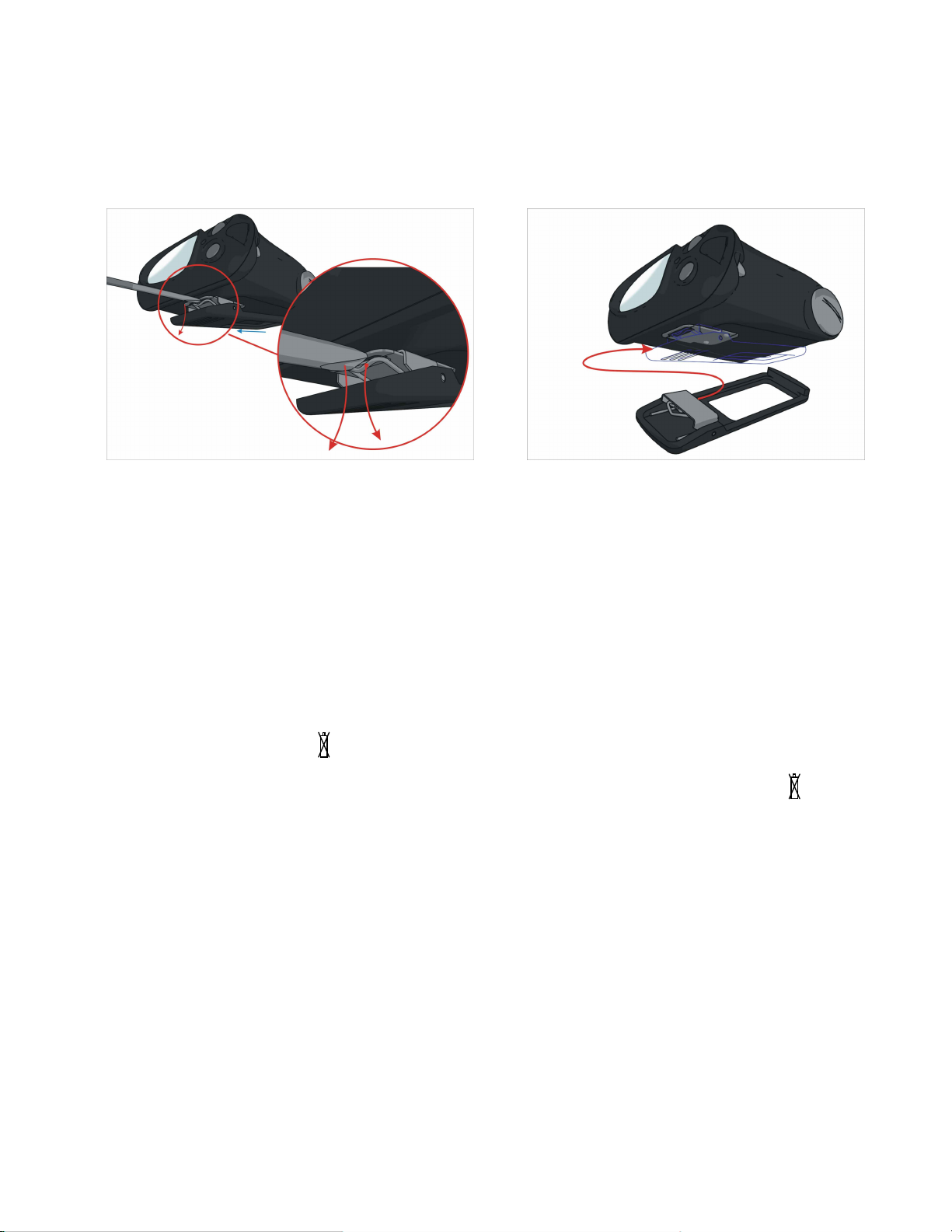
CLAMP INSTALLATION AND REMOVAL
A removable clamp is provided to the indicator for wearing at the waist belt. The clamp may be
removed with the aid of a screw driver, as shown in fig.1a. The clamp is installed according to fig. 1б.
By an individual order the indicator may be provided with a protecting housing made of synthetic
cloth , also providing possibility of wearing at the waist belt. When the protecting housing is used, the clamp
is recommended to be removed.
а) b)
Figure 1
INSTALLATION AND REPLACEMENT OF POWER SUPPLY CELL
The indicator is supplied without a supply cell installed.
For installation of the supply cell a cover of the supply section is to be unscrewed (11) (figure 2) with
the aid of a special spanner included to the supply set; to be installed to the supply cell by observing polarity
(the cell electrode marked with "+", must be directed inside the indicator); the cover of the supply section is
to be restored.
When the supply cell is installed the indicator is automatically switched on.
During switching on and during operation of the indicator periodic control is effected of voltage in
the supply cell. If the voltage becomes lower than 1,1 V, a mark “ ” is induced in the left lower part of the
LCD, and a light and sound (and/or vibrating) signal is given). In this case the supply cell should be
replaced.
Note – After appearance of a discharge symbol on the LCD the device retains workability for
at least 8 hours (with the normal background level).
The user may disconnect the indicator of the supply cell discharge for approximately 30
minutes by a short pressing the MODE button. Being so, signaling by operation thresholds will be
switched on.
CONTROL BUTTONS. INDICATION AT LCD
Two push buttons for the device control are located on the front panel of the indicator: (MODE) and
(LIGHT) , a liquid crystal display (LCD), a window of the IR transmitter-receiver, a light diode (LED),
figure 2.
9
 Loading...