

Page 1

X-RAY AND GAMMA RADIATION PERSONAL DOSIMETERS
РМ1621
Models:
РМ1621
РМ1621А
РМ1621М
РМ1621МА
OPERATING MANUAL
Page 2

2
CONTENTS
1 DESCRIPTION AND OPERATION OF THE DOSIMETER .............................................. 4
1.1 Application Range ...................................................................................................... 4
1.2 Delivery kit .................................................................................................................. 5
1.3 Specifications ............................................................................................................. 6
1.4 Design and theory of operation ................................................................................. 11
2 USE OF THE DOSIMETER ............................................................................................ 15
2.1 General guidelines .................................................................................................... 15
2.2 Safety instructions .................................................................................................... 15
2.3 Preparation for use ................................................................................................... 15
2.4 Use of the dosimeter................................................................................................. 15
3 MAINTENANCE ............................................................................................................. 25
4 TROUBLESHOOTING.................................................................................................... 26
5 VERIFICATION METHOD ................................ .............................................................. 27
5.1 Introduction ............................................................................................................... 27
5.2 Verification procedures and tools ............................................................................. 27
5.3 Verification officers’ qualification requirements ......................................................... 27
5.4 Safety requirements.................................................................................................. 27
5.5 Verification conditions ............................................................................................... 28
5.6 Pre-verification procedure ......................................................................................... 28
5.7 Verification procedure ............................................................................................... 28
5.7.1 External examination of the instrument .................................................................. 28
5.7.2 Carrying out verification (testing) ........................................................................... 28
5.7.3 Metrological examination ....................................................................................... 28
6 STORAGE AND SHIPPING ........................................................................................... 31
7 WARRANTY ................................................................................................................... 32
ATTACHMENT A
Typical instrument anisotropy (data are normalized to the calibration direction 0o) .......... 33
ATTACHMENT B
DIAGRAM OF DOSIMETER ROTATION TO MEASURE ANGULAR RESPONSE .......... 34
ATTACHMENT C
OVERALL DIMENSIONS, EFFECTIVE CENTER OF THE DOSIMETER DETECTOR .... 35
Page 3

3
This Operating Manual combined with the logbook and passport describes the design,
operation and use of the X-ray and gamma radiation personal dosimeter:
- PM1621;
- РМ1621А;
- РМ1621М;
- РМ1621МА
(further dosimeter or instrument).
The Operating Manual includes the general description, specifications of the
dosimeter, as well as some other information necessary for the proper operation of the
dosimeter and a full realization of its possibilities.
During manufacturing of the dosimeter some changes may be introduced in its
electrical scheme and construction that do not influence the specifications and
metrological parameters and, therefore, may be not specified in this manual.
Page 4

4
1 DESCRIPTION AND OPERATION OF THE DOSIMETER
1.1 Application Range
Dosimeter is designed for:
- continuous measurement of the personal dose equivalent (further dose
equivalent or DE) of external gamma and X-ray (further - photon) radiation Hp(10);
- continuous measurement of the time of the DE accumulation;
- continuous measurement of the personal dose equivalent rate of external photon
radiation
)10(
.
p
H
(further dose equivalent rate or DER);
- communications of information accumulated and stored in a non-volatile memory
through infra-red (IR) communication channel (the protocol is compatible with IrDA
interface) into the personal computer (PC) using the internal or external IR adapter.
Dosimeter is manufactured in four models:
- X-ray and gamma radiation personal dosimeter РМ1621;
- X-ray and gamma radiation personal dosimeter РМ1621А. Differs from РМ1621
model by extended DER measurement range;
- X-ray and gamma radiation personal dosimeter РМ1621М. Differs from РМ1621
model by search mode and integrated vibro and light alarm;
- X-ray and gamma radiation personal dosimeter РМ1621МА. Differs from РМ1621
model by extended DER measurement range, search mode and integrated vibro and light
alarm.
The dosimeters may be used independently or as a part of a system for everyday,
efficient and emergency dosimetric control of the personnel and people at sites, production
facilities and units, where there is a potential or real risk of exposure to external X-ray and
gamma radiation by officers of customs and border services, personnel of nuclear
facilities, radiological and isotope laboratories, officers of the emergency services, civil
defense, fire brigades, police, as well as in other spheres of use where there is a necessity
in measurement of the personal dose equivalent and personal dose equivalent rate,
alarming of the exceeding of the preset dose and dose rate levels, information about the
dose accumulation and conduct of the dose rate in time, as well as association of the
measured parameters with an individual, systematization and complex analysis of the
accumulated dosimetric information.
Operating conditions:
- ambient air temperature from - 40 up to 60 C;
- relative humidity up to 98% at the temperature 35 C;
- pressure from 84 up to 106,7 kPa.
Atte ntio n! LCD will still continue to indicate the readings when the
instrument is heated up +50 С.
Page 5
5
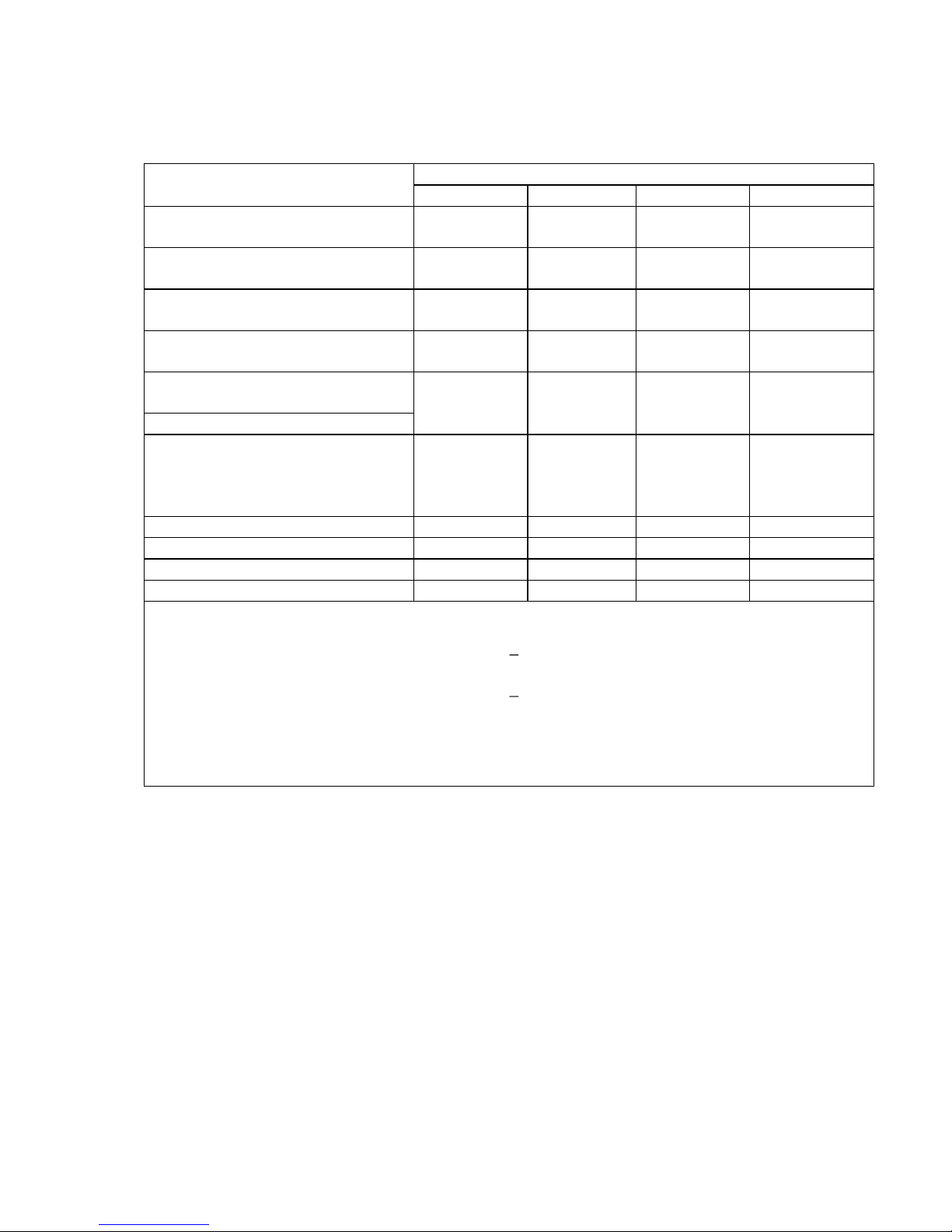
1.2 Delivery kit
1.2.1 Delivery kit of the dosimeter corresponds to the Table 1.1.
Table 1.1
Item, type
Quantity, pcs
РМ1621
РМ1621А
РМ1621М
РМ1621МА
X-ray and gamma radiation
dosimeter – РМ1621
1 - -
-
X-ray and gamma radiation
dosimeter - РМ1621А
- 1 -
-
X-ray and gamma radiation
dosimeter - РМ1621М
- - 1
-
X-ray and gamma radiation
dosimeter - РМ1621МА
- - -
1
Accessories set:
- IR channel adapter 1)
1 1 1
1
- Power supply element
РANASONIC POWER LINE LR6
AA
2; 5)
or Power supply element
Energizer L91BP-2 AA
3; 5)
1 1 1
1
-software
1 CD
1 CD
1 CD
1 CD
Operating manual 4)
1 1 1
1
Cover 5) 1 1 1 1
Packaging 1 1 1
1
1)
Supplied by customer request, by separate order;
2)
Used within the temperature range of minus 20 plus 60°С. Usage of other batteries with similar
parameters is allowed;
3)
Used within the temperature range of minus 20 plus 60°С. Usage of other batteries with similar
parameters is allowed;
4)
Methods of calibration are included;
5)
Supplied on agreement with a customer (buyer).
Page 6

6
1.3 Specifications
1
Operating mode:
- measurement of photon radiation DER;
- measurement of photon radiation DE;
- indication of settings;
- search (for РМ1621М, РМ1621МА);
- indication of partial and critical battery
discharge;
- audio and (additionally for РМ1621М,
РМ1621МА) light and vibro alarm activation
when DE or DER thresholds are exceeded
- indication of the dosimeter’s number ("blind
dosimeter");
- PC data exchange
2
DER measurement range
- for РМ1621, РМ1621М
0.1 Sv/h – 100 mSv/h
- for РМ1621А, РМ1621МА
0.1 Sv/h – 1.00 Sv/h
DER indication sub-ranges
0,01 – 9,99 Sv/h;
10,0 – 99,9 Sv/h;
100 – 999 Sv/h;
1,00 – 9,99 mSv/h;
10,0 – 99,9 mSv/h;
100 – 200 mSv/h (РМ1621, РМ1621М);
100 – 999 mSv/h (РМ1621А, РМ1621МА);
1,00 – 2,00 Sv/h (РМ1621А, РМ1621МА).
- DER analogue scale (seven
segments) in a logarithmic gauge
Number of indicated segments (from left to
right) corresponds to the following DER
threshold values on the LCD display:
- one segment – 0.1 Sv/h;
- two segments – 1 Sv/h;
- three segments –- 10 Sv/h;
- four segments – 100 Sv/h;
- five segments – 1 mSv/h;
- six segments – 10 mSv/h;
- seven segments – 100 mSv/h
3
Maximum permissible intrinsic relative
error of DER measurement
(15 + К1/ + К2 ) %,
where DER value, mSv/h;
К
1
– coefficient 0.0015 (mSv/h);
К
2
– coefficient 0.01 (mSv/h)-1
4
DE measurement range
1.0 Sv 9.99 Sv
5
Maximum permissible intrinsic relative
error of DE measurement
15%
6
DE measurement range
0.01 Sv – 9.99 Sv
Indication sub-ranges:
0.01 – 9.99 Sv;
10.0 – 99.9 Sv;
100 – 999 Sv;
1.00 – 9.99 mSv;
10.0 – 99.9 mSv;
100 999 mSv;
1.0 Sv – 9.99 Sv
7
Discreteness of DE accumulation time
indication
1 h
Page 7
7
8 The dosimeter provides inputting, storage in a non-volatile memory and continuous
control of two DER and DE threshold levels within the whole measurement range, various
audible alarms, as well as vibro and light alarms (additionally for РМ1621М, РМ1621МА)
at exceeding of the preset first and second threshold levels.
Discreteness of threshold level setting
Unit of lower-order indicated position
9
Registered energy range
10 keV – 20 МeV
Energy response relative to
0.662 MeV (
137
Cs), no more than
30%
10
Coefficient of variation (deviation of the
dosimeter’s readings caused by statistic
fluctuations) at DER measurement at a
confidence coefficient 0,95, no more
than
10%
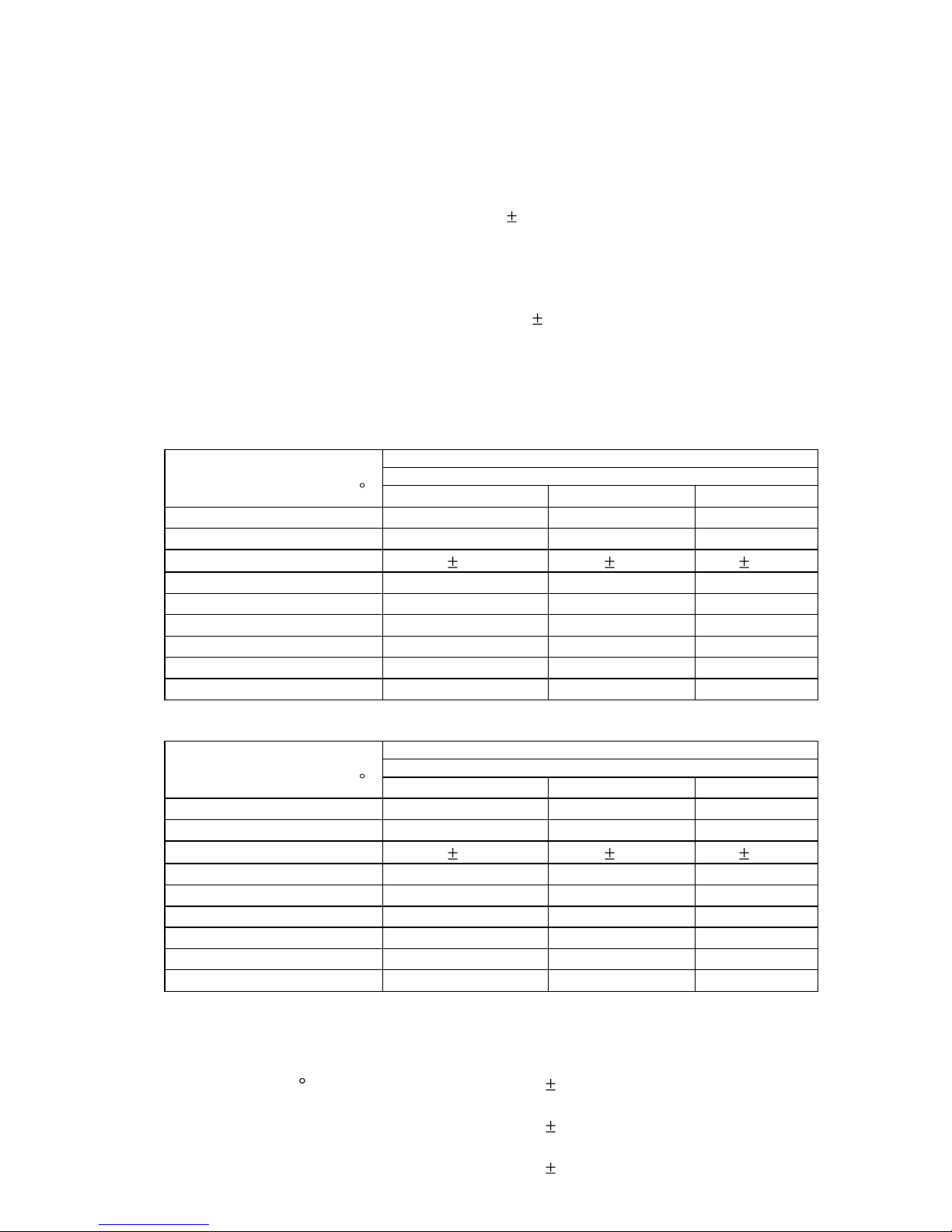
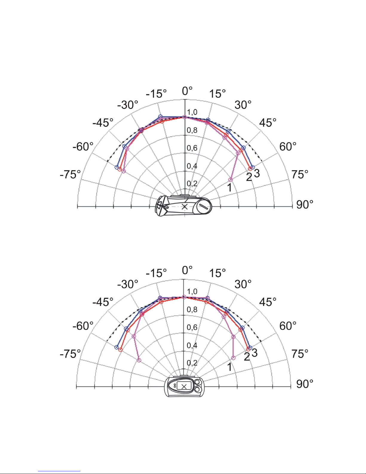
11 Anisotropy (type dependence is given in Attachment A) of the Dosimeter for each
energy does not exceed values (in %) presented in Table 1.2, when the Dosimeter is
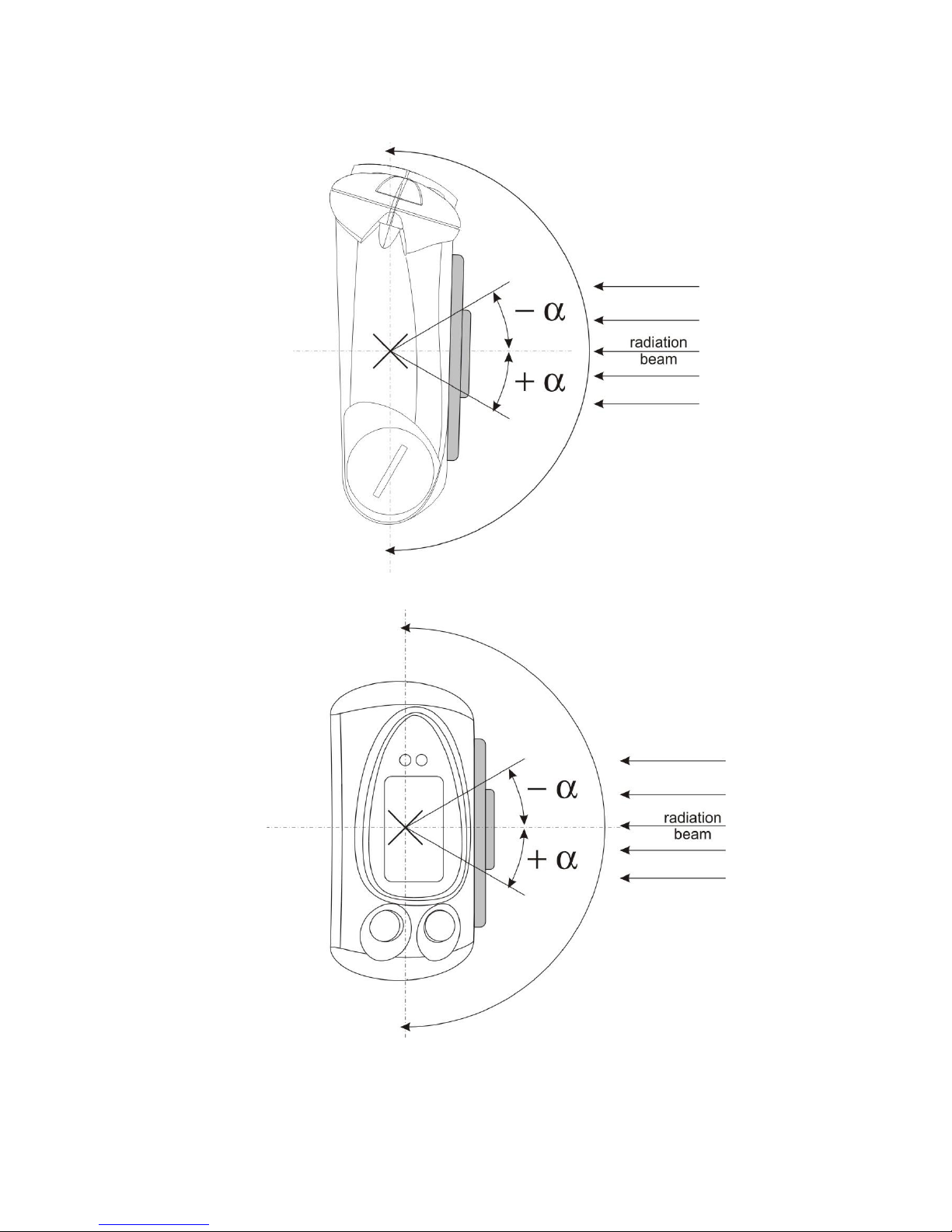
rotated in the horizontal plane (Attachment B, figure B.1) and values (in %) presented in
Table 1.3, when the Dosimeter is rotated in the vertical plane (Attachment B, figure B.2).
Table 1.2
Angle of detection relative to
the direction of graduation,
Energy of gamma radiation, MeV
Anisotropy
0.059
0.662
1.25 0 0
0 0 15
± 5
± 5
± 5
30
10
10
10
45
± 20
± 15
± 15
60
± 40
± 20
± 20
-15
± 5
± 5
± 5
-30
± 10
± 10
± 10
-45
± 20
± 15
± 15
-60
± 40
± 20
± 20
Table 1.3
Angle of detection relative to
the direction of graduation,
Energy of gamma radiation, MeV
Anisotropy
0.059
0.662
1.25 0 0
0
0
15
± 5
± 5
± 5
30
10
10
10
45
± 20
± 15
± 15
60
± 40
± 20
± 20
-15
± 5
± 5
± 5
-30
± 10
± 10
± 10
-45
± 20
± 15
± 15
-60
± 40
± 20
± 20
12
Maximum permissible additional relative
error of DER measurement:
- at temperature variations from minus
40 to plus 60 С
10%
- at relative humidity of ambient air 98 %
at 35 °С
10%
- at power voltage variations from
nominal value to limiting voltage values
5%
Page 8

8
- on exposure to magnetic field of 400
A/m strength
5%
- on exposure to radio frequency
electromagnetic fields of 30 V/m
strength
5%
13
LCD backlight at pressing LIGHT/SET
button
3-5 s
14
Instability of readings during 24 hour
continuous work, no more than
5%
15
Response time when DER value is
increased more than 10 times, from
initial low DER value to finite fixed high
DER value exceeding 10 Sv/h, no
more than
5 s
16
Response time when DER value is
decreased more than 10 times, from
initial high to finite fixed low DER value
exceeding 10 Sv/h, no more than
10 s
17
PC communication
- by a special program using IR
communication channel adapter
18
In the mode of data transmission to PC
the dosimeter provides the following
functions:
1) permission or prohibition the following
be displayed on LCD:
- DER or DE photon radiation measured
value indication;
- relative mean square error of average
value of measurement result with 0.95
probability (statistical error) in percents;
- dosimeter number (“blind dosimeter”);
2) reading from PC into dosimeter and
storing in instrument’s non-volatile
memory the following information:
- dosimeter serial number;
- history of DE and DER accumulation at
user set time periods;
- DE (DER) values when set thresholds
are exceeded, as well as time, date and
month, when set thresholds where
exceeded;
- DE and DER set thresholds values;
- service information;
3) following information is recorded from
PC to dosimeter:
- values of DE and DER thresholds
being set;
- current date and time for DE
accumulation history;
- operation modes.
19
In the search mode the dosimeter
PМ1621М, РМ1621МА) enables
following functions:
- detect and locate the photon radiation
sources on the basis of audio-, vibroand light (LED blinking) alarm signal
frequency changes;
- search mode on/off;
- search mode on/off state indication.
Page 9

9
20
Sound pressure level at the distance of
20 cm (for РМ1621М, РМ1621МА), no
less
85 dB (А).
21
Power supply
1.5 (+ 0.1; minus 0.4) V (one AA type
battery)
22
Period of continuous operation of the
dosimeter from one battery, using LCD
backlight not more than 20 s/day,
audible alarm – not more than 20 s/day
and at an average value of the
measured DER up to 0.3 Sv/h:
- at a temperature from 0 up to 60 C
12 months
- at a temperature minus 40 C, at least:
6 months
23
Protection degree of the dosimeter’s
case
IP67
24
The dosimeter is proof against the
action of:
- temperature of an ambient air from
minus 20 up to plus 60 C with indication
of measurement results on LCD;
- temperature of an ambient air from
minus 40 up to minus 20 C without
indication of measurement results on
LCD but with recording of measurement
results in a non-volatile memory;
- relative humidity of an ambient air up
to 98 % at 35 C;
- atmosphere pressure from 84 up to
106,7 kPa
25
The dosimeter is proof against:
- sinusoidal vibration in the frequency
range 5 - 35 Hz and bias amplitude for
frequencies lower than the transition
frequency 0.75 mm;
- shocks with acceleration 100 m/s2,
duration of shock pulse 2-50 ms, shock
rate is 60 - 180 shocks per minute
26
The dosimeter meets drop test against a
concrete surface from the height
0,7 m
27
The dosimeter is proof against the
action of static and variable magnetic
fields of strength
up to 400 А/m
28
The dosimeter is proof against the action of radio frequency electromagnetic fields up
to 30 V/m in the frequency range from 80 to 1000 MHz, from 800 to 960 MHz, from
1.4 to 2.5 HHz of strength (in electromagnetic emission envoronment of digital
radiophone)
- the dosimeter is proof against the action of electrostatic discharges, test level 3 (air
discharge, 8 kV, contact discharge 6 kV) , performance criterion В;
- dosimeter corresponds electromagnetic compatibility state standard of
manufacturing country (EN 55022:1998 (class B)) requirements by the level of emitted
radio noise
29
The dosimeter in a transport package is
proof against the action of:
- temperature from minus 50 up to plus
50 C;
- humidity up to 100 % at 40 C;
- shocks with acceleration 98 m/s2,
duration 16 ms;
- vibrations with frequency 5-35 Hz and
bias amplitude 0.75 mm
Page 10

10
30
Weight, no more
РМ1621, РМ1621А
РМ1621М, РМ1621МА
0.165 kg
0,185 kg
Weight in package
not more than 0.4 kg
31
Overall dimensions, no more
not more than 87х72х39 mm
32
Reliability parameters:
- average full operating time
no less than 20000 h;
- average service life
no less than 10 years
- average time of recovery
no more than 60 min
Note – For addition information about dosimeter, please visit
www.polimaster.com.
Page 11
11
1.4 Design and theory of operation
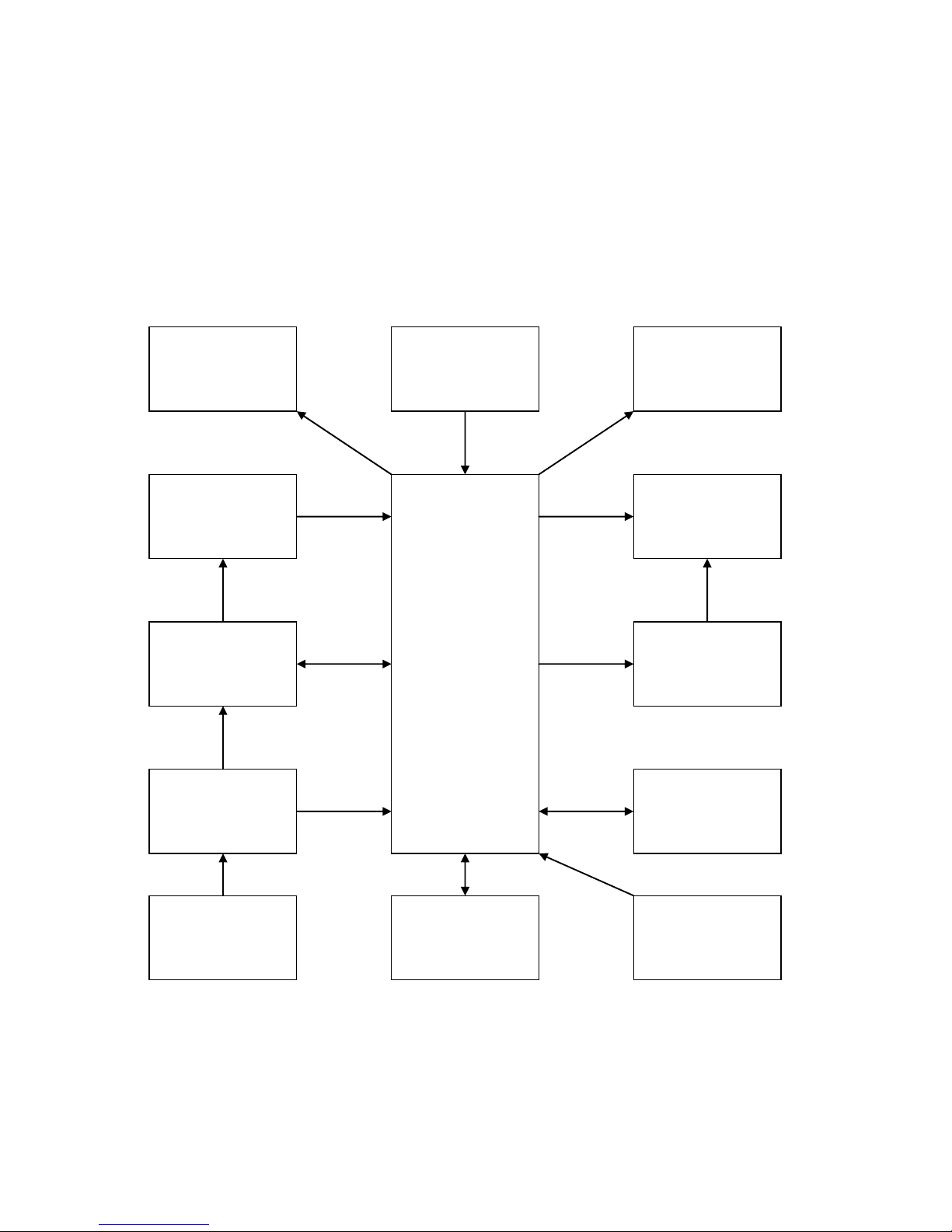
1.4.1 The dosimeter comprises the following main blocks and modules:
- radiation detector;
- microprocessor;
- LCD;
- secondary power supply;
- IR-transceiver;
- non-volatile memory.
The block diagram of the dosimeter is shown in Figure 1.1.
Figure 1.1 – Block diagram of the dosimeter
A Geiger-Muller tube with a filter for spatial-energy formation of sensitivity, which
converts photon radiation quanta to electric pulses, is used as a radiation detector. The
detector has a high-voltage power supply.
Backlight
driver
Quartz
generator
Microprocessor
IR-
transceiver
Battery
1.5 V
Secondary
power supply
Radiation
detector
DAC
of temperature
compensaton
LCD
RAM
High voltage
power supply
Control
buttons
Alarm
(audible, vibro
and light)
Page 12

12
The microprocessor controls the dosimeter’s operating modes, backlight driver,
audible alarm driver, infrared communication channel, LCD, non-volatile memory, highvoltage power supply of the detector, operates the control buttons, performs all the
necessary calculations, self-diagnostics.
The dosimeter’s operating algorithm ensures continuity of the measurement
process, statistical processing of the measurement results, a prompt adaptation to the
variation of level of the photon radiation dose rate (setting the time of measurement in
inverse dependence on the dose rate) and effective output of the information obtained to
the LCD. The IR-communication channel provides an exchange of information with PC.
The dosimeter has an internal non-volatile memory that allows the information
accumulation and storage.
Secondary power supply provides transformation of the battery’s voltage 1.5 V into
a stable voltage 3.0 V necessary for the dosimeter’s power supply.
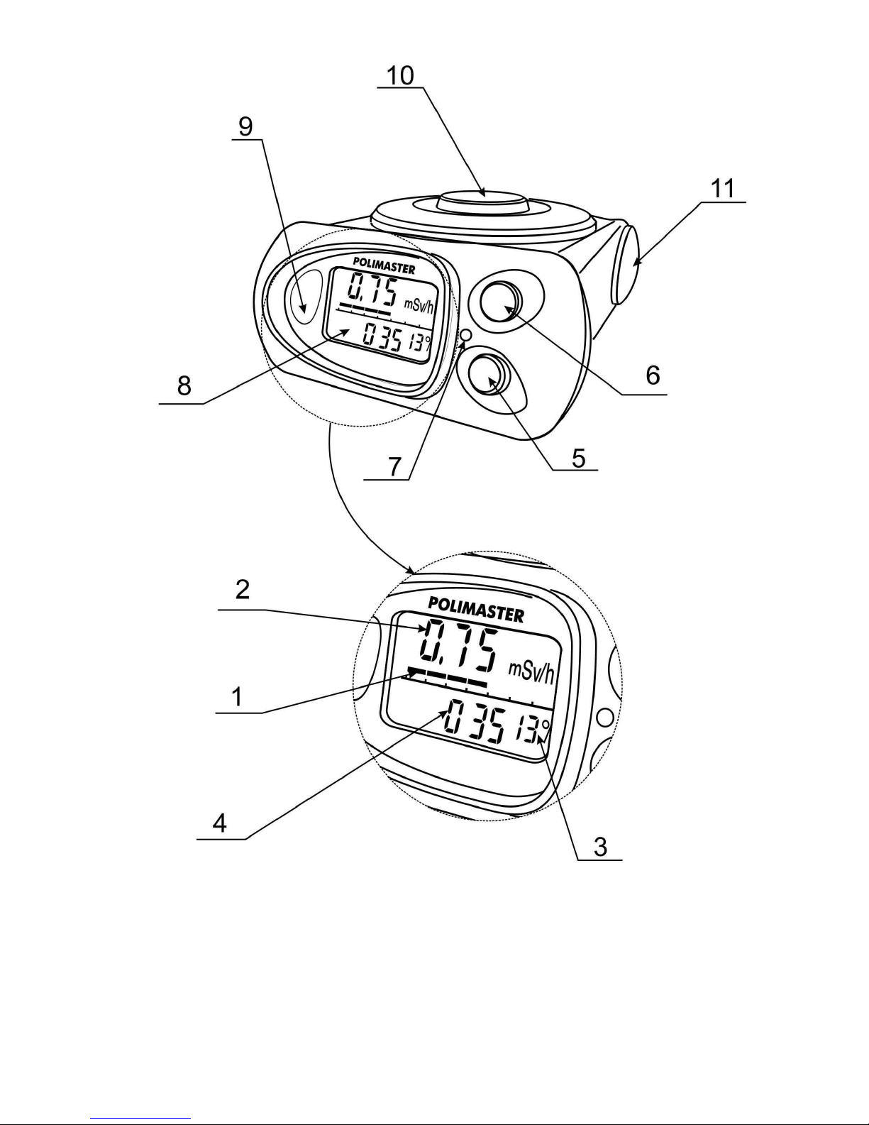
1.4.2 The Dosimeter is designed as a unit housed in a plastic shock-proof case.
General overview of the dosimeter and its parts are shown in Figure 1.2. Indication
elements, positions 1 4, are on the LCD (8).
1 – DER analog scale (seven segments) for effective control over radiation
situation, analog scale (four segments) – sound pressure level indicator in the search
mode;
2 – DER digital panel in DER measurement mode, DE in DE measurement mode,
year of production in the dosimeter’s number indication mode, indication of IR
communication channel switch on/off in the PC communication mode;
3 – digital panel of indication of statistical error in percents in DER measurement
mode, DE accumulation time indication in thousands of hours (h) in DE measurement
mode, month of production in the dosimeter’s number indication mode;
4 – digital panel of indication of time of averaging DER values (in seconds) in DER
measurement mode, of DE accumulation time in DE measurement mode;
5 – the (LIGHT/SET) button for switching on LCD backlight, switching on PC
communication mode, entering the set mode and exiting it;
6 – the (MODE) button for selecting the dosimeter’s indication mode (DER, DE,
the dosimeter’s number, PC communication);
7 – light alarm outlet;
8 – LCD;
9 – IR-transceiver window;
10 – detector;
11 – screw-cover of battery compartment.
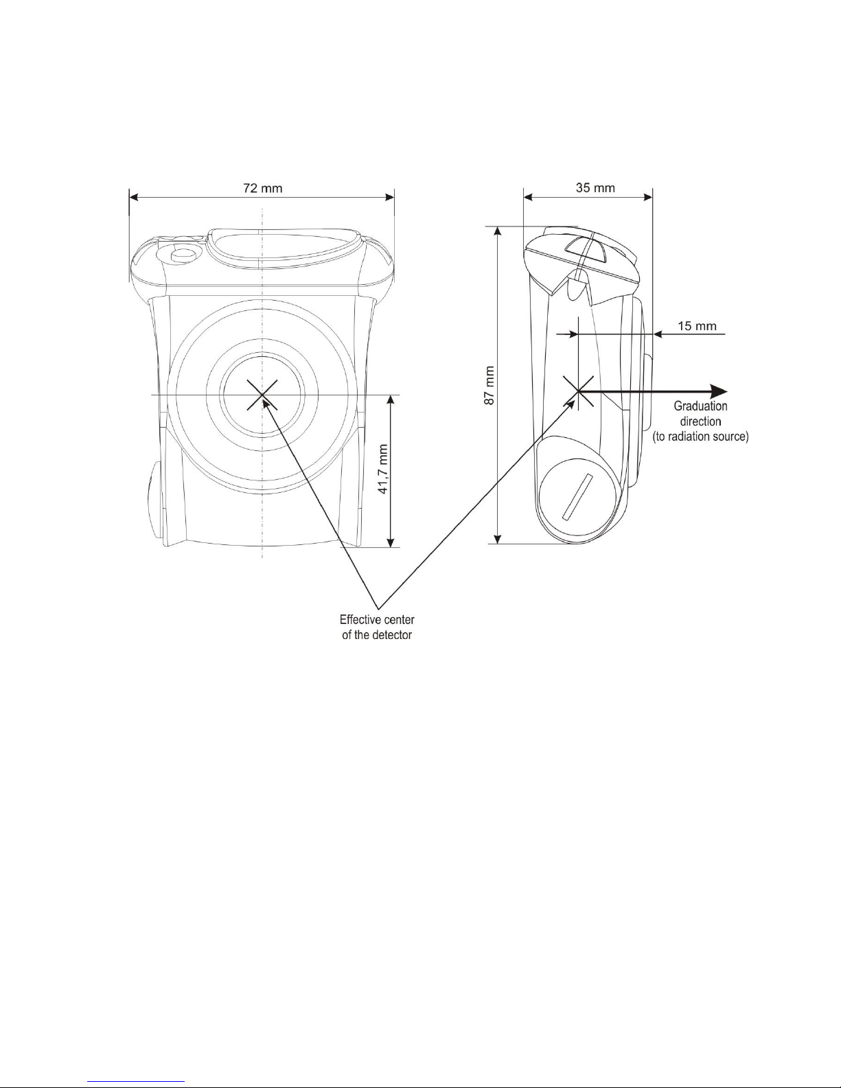
A direction of calibration and the detector effective center relative to which the
factory calibration is performed are placed at a 15 mm distance from the dosimeter
detector’s surface (Attachment C).
The total surface density of the walls surrounding the detector is 1 g/cm2 that
provides the detector shielding from the background beta radiation.
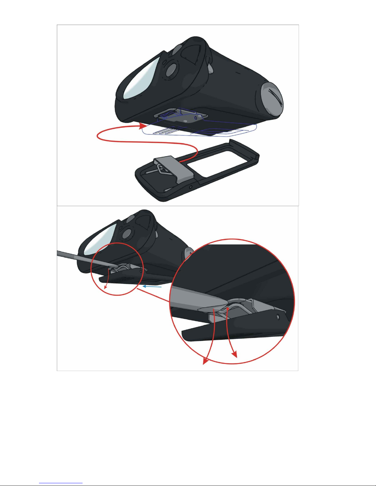
РМ1621М and РМ1621МА dosimeters are equipped with removable clip to be worn
on belt. See Figure 1.3 for the way to demount the clip from the dosimeter body.
Dosimeter can be supplied with protective case made from synthetic fabric so that
user can wear it on the belt. Polimaster recommends demounting the clip when wearing
dosimeter in protection cover.
Page 13
13
Figure 1.2 – General overview of the dosimeter
Page 14
14
Figure 1.3 – Demounting the clip from РМ1621М and РМ1621МА
Page 15

15
2 USE OF THE DOSIMETER
2.1 General guidelines
When purchasing the dosimeter it is necessary to check the delivery kit (chapter
1.2.1) and the proper operation of the instrument in all the operation modes (chapter 2.4).
Protect the instrument from shocks and mechanical damages. Avoid exposing the
dosimeter to hostile environments, organic solvents and open fire.
2.2 Safety instructions
During the dosimeter adjustment, checking, repair, maintenance and verification, if
the radioactive sources are used, the regulations for work with radioactive materials and
other radiation sources, as well as Standards of radiation safety should be followed.
2.3 Preparation for use
2.3.1 It is necessary to study all sections of the present operating manual before
using the dosimeter.
2.3.2 Unpack the dosimeter.
2.3.3 Switching on:
- unscrew the battery compartment’s cover using the screwdriver;
- insert the battery, observing the polarity (battery’s electrode marked with “+”
should be directed inside the dosimeter);
- fix the battery compartment’s cover in its place.
Right after inserting the battery the dosimeter performs LCD testing (all the
segments and graphic symbols should be displayed for about 2 s and then disappear),
then the dosimeter should enter the measurement mode. One minute after inserting the
battery the dosimeter is ready for use.
2.3.4 Place and fix the dosimeter, detector outwards, on a breast pocket of overalls
or inside it.
Attention! If the dosimeter is expected to be used under conditions when the
dose rate value is higher than 0.1 mSv/h, it is recommended to insert a new battery.
2.4 Use of the dosimeter
2.4.1 Dosimeter operation modes
- photon radiation DER measurement mode;
- photon radiation DE measurement mode;
- dosimeter’s number indication mode (“blind dosimeter”);
- mode of data transmission to PC;
- search mode (for РМ1621М and РМ1621МА);
- mode of audio alarm state indication;
- mode of vibro alarm state indication (for РМ1621М, РМ1621МА)
- partial or critical battery discharge indication mode;
- settings mode;
- audible alarm mode at the exceeding of the preset DE or DER thresholds, as well
as vibro and light alarm mode for РМ1621М and РМ1621МА additionally.
The dosimeter’s non-volatile memory ensures storage of the following values when
replacing the battery for the moment of the battery’s removal:
- accumulated dose (DE);
- DE accumulation time;
- DE and DER accumulation history;
- preset DER and DE thresholds values.
Page 16

16
When using the dosimeter in a temperature range from -40 up to -20 C the
Dosimeter provides performance of the dosimetric functions without displaying the result of
measurement on LCD. When returning the dosimeter into conditions with a temperature
higher than -20 С LCD operates in a normal way.
The dosimeter performs continuous DER and DE measurement, DE accumulation
time counting in all modes, excluding an active mode of data transmission to PC (Ir/on).
Standard configuration of the dosimeter when shipping ensures indication of the
following parameters and functions performed:
DER measurement mode – On
On a display (2), figure 1.2 – DER values output
On a display (3) – output of statistical error values, % - Off
On a display (4) – output of DER values averaging - Off
Thresholds setting enable - On
Audible alarm - On
DE measurement mode – On
On a display (2), figure 1.2 – DE values output
On a display (3) – output of DE accumulation time values in thousands hours
(symbol “h” is indicated at DE accumulation time less than a thousand hours).
On a display (4) – output of DE accumulation time values in hours - On
On a display (4) – output of the values of time remaining for staying at the working
place - Off
Thresholds setting enable On
DE reset On
Audible alarm On
Dosimeter’s number indication mode – On
On a display (2), figure 1.2 - dosimeter’s number;
On a display (3) - month of the dosimeter’s production;
On a display (4) - year of the dosimeter’s production;
Audible alarm - On
Search mode - On.
Audio alarm indication mode - On.
Vibro alarm indication mode - On.
2.4.2 Selection of an indicated parameter
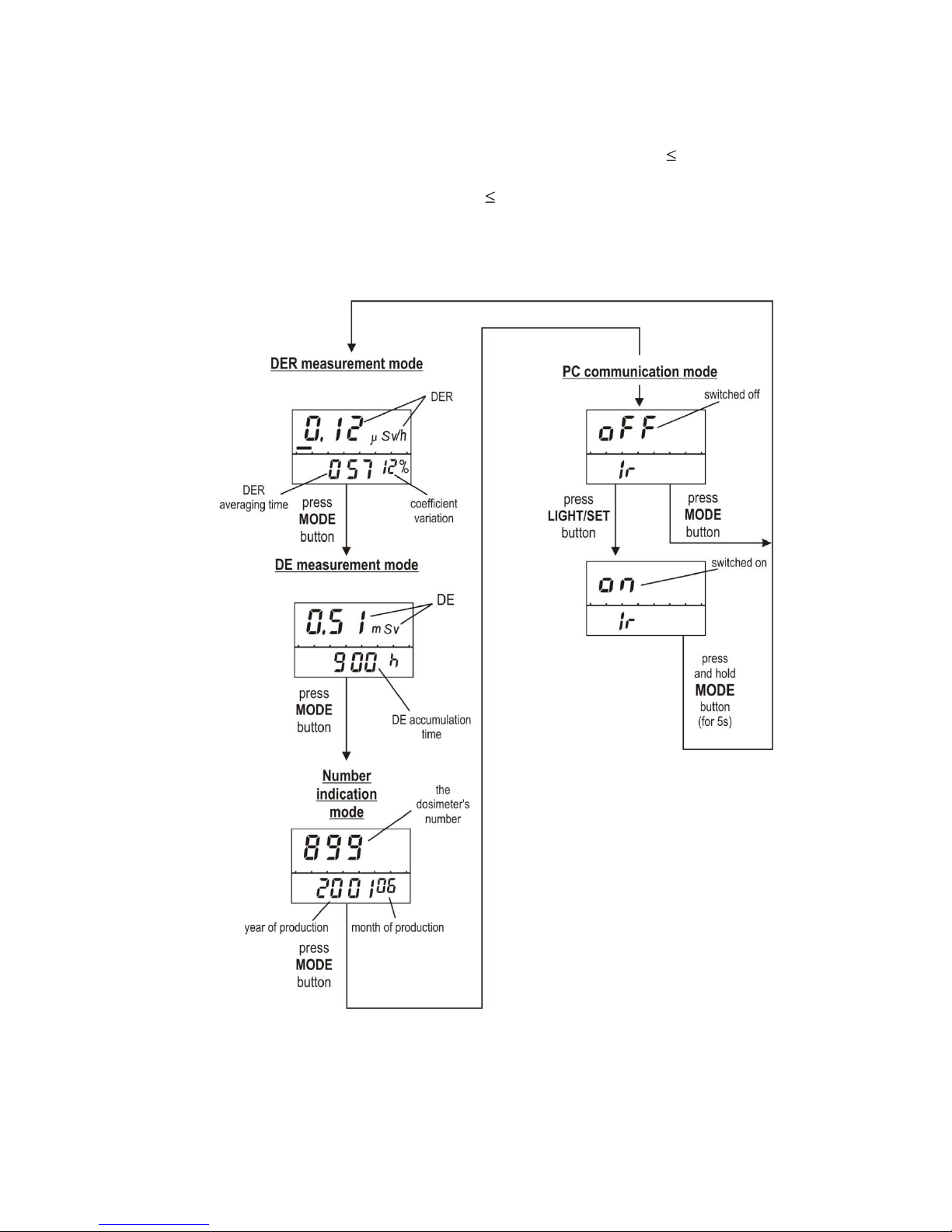
Modes of DER, DE, dosimeter’s number and data transmission to PC indication are
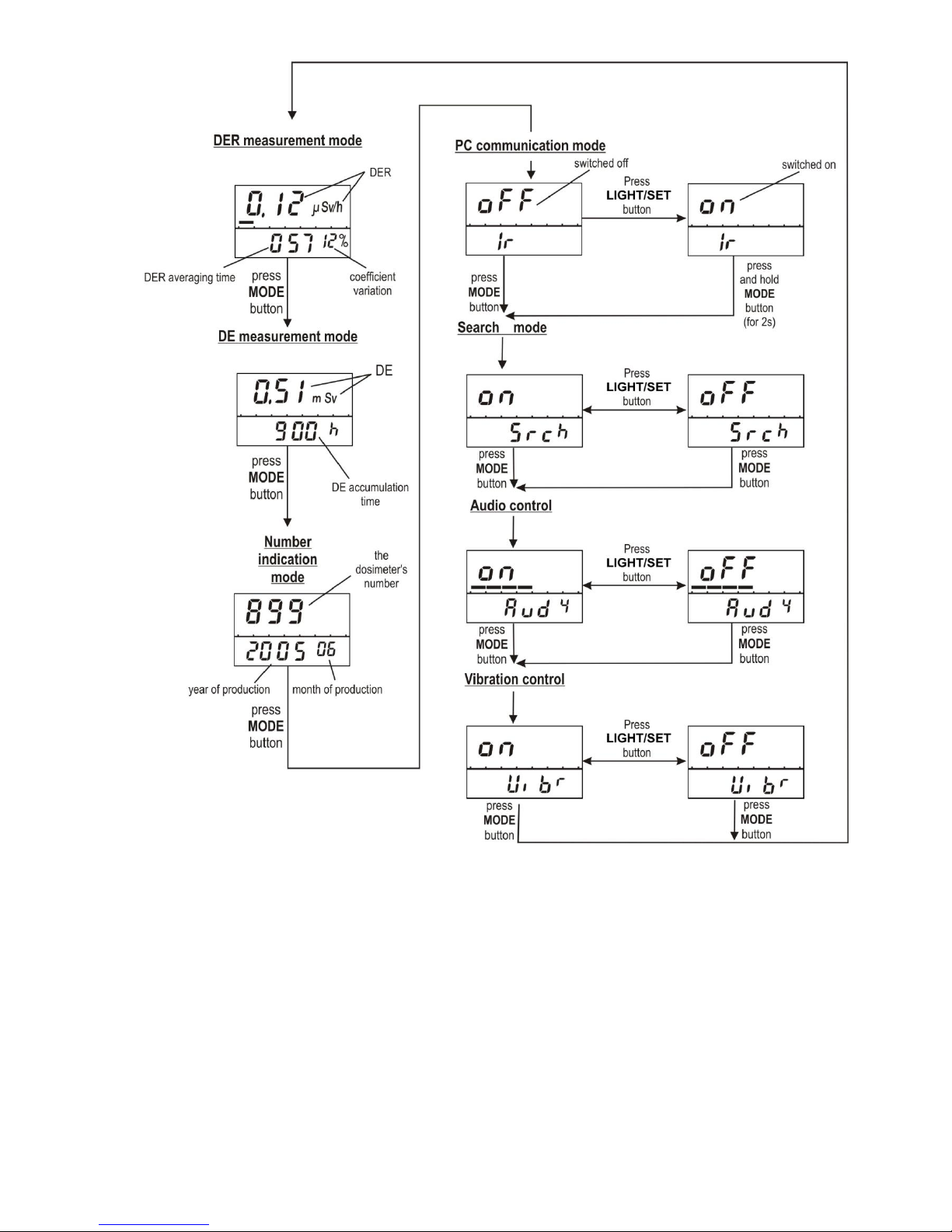
switched on by a successive pressing of the MODE button (figure 2.1 and 2.2).
The dosimeter allows switching on/off all the above-mentioned indication or
measurement modes. Change of the configuration is performed in the mode of data
transmission to PC.
2.4.3 DER measurement mode
In the DER mode (figure 2.1 and 2.2) the following values are indicated on the LCD:
- DER ( Sv/h, mSv/h, Sv/h);
- DER on the analogue scale in a logarithmic gauge (seven segments);
- statistical error in percents;
- averaging time of DER values (Range of the averaging time indication is from 1 up
to 2999 s. If the averaging time exceeds 2999 s, the symbols “- - -” are indicated on the
LCD).
Page 17

17
If the measured DER value is over the upper limit of the DER indication range
(200 mSv/h for the РМ1621, РМ1621М and 2.0 Sv/h for РМ1621А, РМ1621МА), the LCD
will show the overload symbol “OL” and non continuous audible signal will sound.
In the DER mode the collected statistics of DER measurement can be reset and the
process of measurement can be reactivated by simultaneous pressing of the
LIGHT/SET+MODE buttons.
2.4.4 DE measurement mode
In the DE mode (figure 2.3) the following values are indicated on the LCD:
- DE ( Sv, mSv, Sv);
- DE accumulation time.
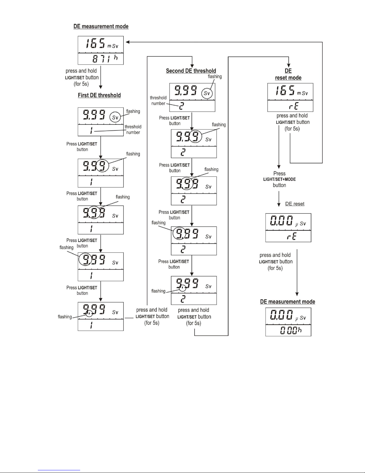
DE and DE accumulation time reset is possible in the set mode by simultaneous
pressing of the LIGHT/SET+MODE buttons (figure 2.3).
In the mode of data transmission to PC it is possible to set an inhibit for DE reset
using the buttons.
There are two methods of measurement of the DE accumulated over a certain period of
time.
The first method (recommended). In the beginning of measurement the DE should
be reset using the keys or the PC and the user software supplied on CD. Then the dose
displayed at the end of the period will be the dose accumulated over the period of
measurement.
The second method. The dose value in the beginning of the period of
measurement should be deducted from the DE value displayed at the end of the period.
In the DE mode the indication (figure 1.2 display (3) and (4)) of values of time
remaining for staying at the working place depending on the current measured DER and
DE values is possible. Calculation of time is performed relative to the second preset DE
threshold (the function may be switched on at the DE measurement mode configuration).
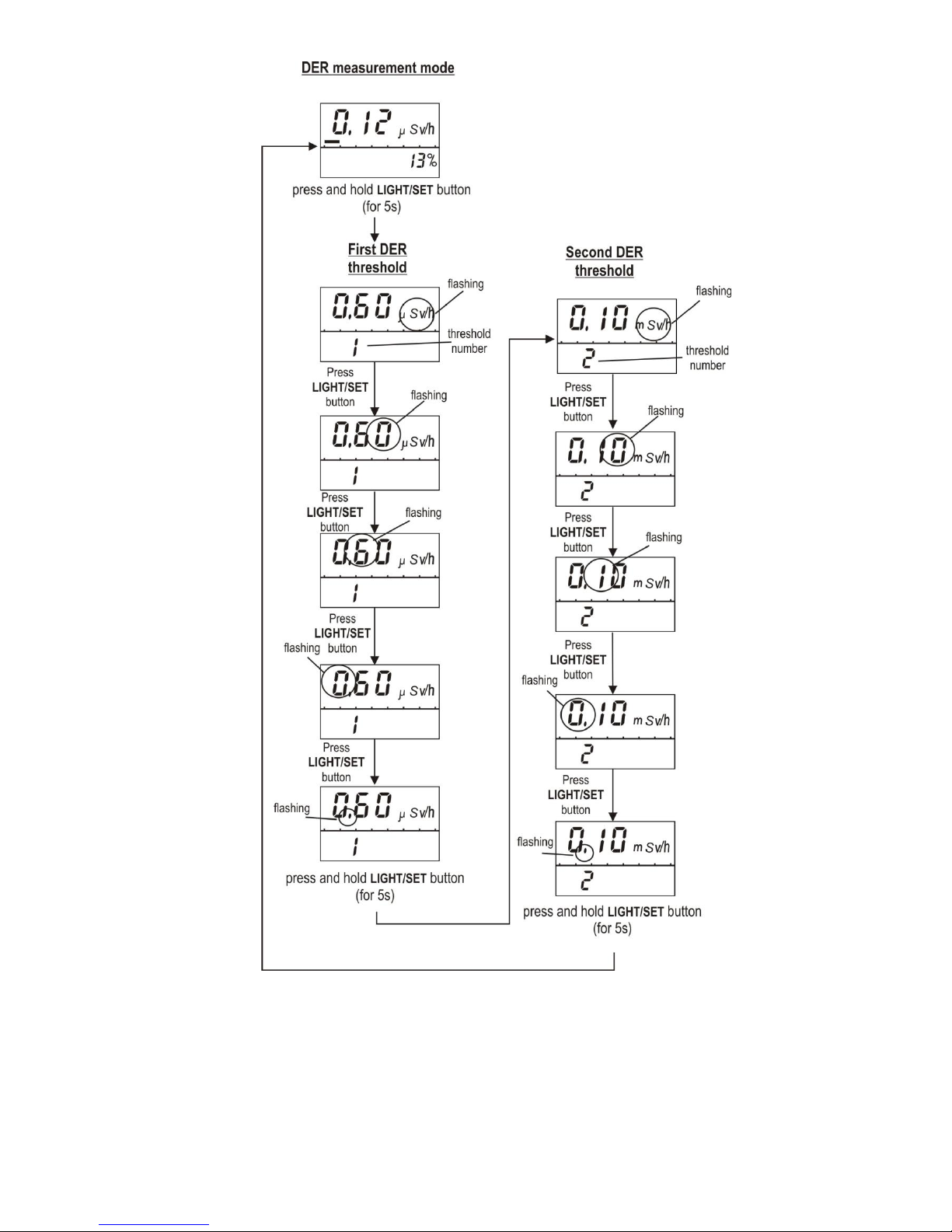
2.4.5 Settings mode
Auxiliary mode of settings (figure 2.4) is meant for verification and (or) setting of the
threshold DE (DER) values, DE and DE accumulation time reset.
Attention! To enter the “set” mode press and hold for about 5 s the
LIGHT/SET button and the parameter to be set will be flashing.
To chose the parameter press and release the LIGHT/SET button.
To change the set parameter:
- rapidly – press and hold the MODE button;
- for exact setting – press and release the MODE button.
The dosimeter will exit the “set” mode by pressing and holding the LIHGT/SET
button or automatically in approximately 90 s.
Inputting the DER (DE) threshold levels into the memory
This procedure can be performed in the DER (DE) measurement mode as well as in
the mode of data transmission to PC. DER (DE) thresholds are inputted during DER (DE)
measurement on the LCD.
Enter the settings mode by pressing and holding the LIHGT/SET button (figure 2.4).
Input successively the first and then the second threshold levels.
Exit the set mode.
In the mode of data transmission to PC it is possible to set an inhibit for changing
the threshold levels using the buttons.
In case of exceeding the value of the first (second) DER (DE) threshold the
dosimeter turns correspondingly into the DER (DE) measurement mode and
noncontinuous (frequent noncontinuous) audible signal will sound.
When DER value decreases below the preset threshold, the audible signal will shut
off. Press any button to silence the alarm sound. The audible signal will shut off
Page 18

18
automatically in approximately 60 s, the repeated audible signal will sound in
approximately 4 min.
2.4.6 The dosimeter’s number indication mode
In the dosimeter’s number indication mode the following items are indicated on the
LCD:
- the dosimeter’s number on a display (2);
- year (4) and month (3) of production.
2.4.7 Mode of data transmission to PC
2.4.7.1 The dosimeter allows storing and transmitting to PC a history (further –
"history") of DE, DER accumulation, events of exceeding the preset DE and DER
threshold values, event of DE reset trough IR communication channel using the buttons.
Selection of the events to be stored in the history, frequency of these recordings is
performed under a special program. History data are inaccessible without IR adapter
(internal or external).
The dosimeter performs data transmission to PC under the user software supplied
on CD through the adapter of IR communication channel over the communications
protocol compatible with IrDA interface.
System requirements to a computer:
- A PC not lower than Pentium III;
- 1 GВ free HDD space;
- printer and unit for operation with IrDA protocol for the exchange of information
with the Dosimeters are necessary for comfort program running;
- The program runs under OS Windows 2000/XP/VISTA, Windows 7.
2.4.7.2 For using the dosimeter in the mode of data transmission to PC it is
necessary to:
- read the user software supplied on CD;
- connect the adapter of IR communication channel to a PC COM port (using the
adapter built in a PC shall be permitted);
- install the unit of IrDA communication in the system and switch on the IR
connection in the mode of searching external IR connection devices;
- install the user software supplied on CD to PC;
- orient the dosimeter and adapter of IR communication channel of the PC by
placing the dosimeter at a distance of 10-20 cm from the adapter of IR channel;
- choose the mode of data transmission to PC using the MODE button (figure 2.1);
- press and release the LIGHT/SET button for PC link startup through IR channel;
- perform readout of the dosimeter's information, following the program's
instructions.
2.4.7.3 Allow or prohibit operation modes (parameters) of dosimeter (РМ1621М,
РМ1621МА):
- DER measurement;
- DER coefficient variations indication;
- indication of DER averaging time;
- DE measurement;
Page 19

19
- DE accumulation time indication;
- indication of counter of the left time of presence on the work place depending in
current measured DER and DE values;
- dosimeter number indication;
- audio alarm;
- setting DER and DE threshold values using buttons;
- reset DE using buttons.
2.4.7.4 Read-out from dosimeter to PC the following information (РМ1621М,
PМ1621МА):
- dosimeter parameters;
- DER history and DE accumulation (date, time, event, value);
- DE value (DER) at the moment of set threshold exceeding, as well as time, date
and month when set thresholds were exceeded;
- values of set DE and DER thresholds;
- service information.
2.4.7.5 Record from PC into dosimeter the following information (РМ1621М,
РМ1621МА):
- dosimeter parameters;
- DE and DER threshold values;
- recording interval of DER history and DE accumulation;
- current time and date for generating DE accumulation history;
- service information.
2.4.8 Search mode (РМ1621М, РМ1621МА)
In the search mode the dosimeter enables functions of detection and localization of
gamma radiation sources (GRS). See figure 2.2 for the way to switch search mode on.
When first DER threshold level is exceeded (GRS are detected), audio, light and
vibro alarms rate will increase as the dosimeter is being moved closer to GRS.
When limiting frequency is reached, the dosimeter will emit continuous audio alarm.
At single pressing of LIGHT/SET button the frequency of audio, light and vibro alarms can
be decreased, that improves dosimeter’s detection power when it gets closer to GRS.
Another pressing the LIGHT/SET button resets the frequency of audio, light and
vibro alarms to initial state. When second DER threshold level is exceeded, dosimeter
emits frequent discontinuous audio, light and vibro alarms.
When doing localization of GRS place the dosimeter so that dosimeter’s effective
center (attachment C, figure C.1) faces the tested object. Hold the dosimeter at the
distance of the tested object no more than 10 cm. Move the dosimeter alongside the
tested object no faster than 10 cm/s.
2.4.9 Indication mode of audio alarm state (РМ1621М, PМ1621МА)
In the indication mode of audio alarm state (figure 2.2) the dosimeter enables
following functions:
- audio alarm on/off;
- indication when audio alarm is on/off;
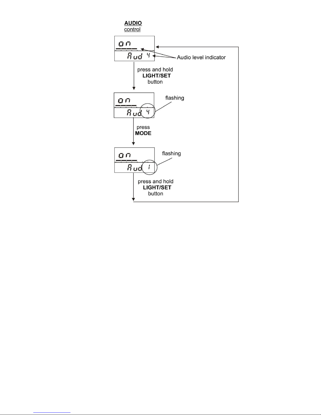
- adjust audio alarm sound pressure (figure 2.5);
- indicate sound pressure level as analogous scale and digitally (from 1 to 4). Level
1 (one line) corresponds to minimum sound level, and level 4 (four lines) corresponds to
maximum sound level.
2.4.10 Indication mode of vibro alarm state (РМ1621М, РМ1621МА)
In the indication mode of vibro alarm state (Figure 2.2) the dosimeter enables
following functions:
- vibro alarm on/off;
Page 20
20
- indication when vibro alarm is on/off.
2.4.11 Partial or critical battery discharge indication mode
The dosimeter controls battery discharge once in 10 minutes.
In case of the battery partial discharge (approximately 1.1 V) the LCD will
indicate the flashing symbol "bat". The battery is to be replaced! (3.3) In case of the
battery critical discharge (approximately 0.9 V) the dosimeter will turn into the DE
measurement mode, the symbol "bat" will become solid, the dosimeter will stop the
measurements, LCD backlight and audible alarm will become locked. The battery is to be
replaced! (3.3)
Figure 2.1 – Select the РМ1621 (РМ1621А) dosimeter operating (indication) mode
Page 21
21
Figure 2.2 – Select the РМ1621М (РМ1621МА) dosimeter operating (indication) mode
Page 22
22
Figure 2.3 – Setting the DE threshold values
Page 23
23
Figure 2.4 – Setting the DER threshold values
Page 24
24
Figure 2.5 – Indication of audio alarm state
(on/off, adjustment of sound volume of РМ1621М (РМ1621МА) dosimeter)
Page 25

25
3 MAINTENANCE
3.1 Maintenance involves preventive services, battery replacement and regular
performance check (according to 2.4.3 - 2.4.5).
3.2 Preventive services include external examination, dusting and decontamination
in the event of radioactive contamination.
For decontamination wipe the case of the dosimeter using a cloth wetted with
ethanol.
3.3 Battery replacement:
- unscrew and remove the cover of the battery compartment;
- remove the old battery;
- insert the new battery observing the polarity (the “+” sign of the battery should
be inwardly directed);
- fix the cover of the battery compartment in its place.
After the battery is replaced, the LCD will display all segments, and then the
dosimeter should enter the measurement mode. All the previous measurements and
parameters necessary for proper operation of the dosimeter are stored in its non-volatile
memory.
NOTE – Insert a new battery before sending a dosimeter for calibration.
Page 26

26
4 TROUBLESHOOTING
The list of possible problems and their solutions are specified in the table 4.1.
Table 4.1
Problem
Possible cause
Solution
1 The LCD indicates “bAt”
message
Battery discharge
Replace the battery
2 No indications on the LCD
Battery discharge
Replace the battery
Battery is inserted
incorrectly
Insert the battery in the proper
way
3 The Dosimeter does not
respond to pressing a
button, the LCD indicates
incorrect symbols
Microprocessor error
condition
Remove the battery and insert
it again in 5 minutes
4 The LCD indicates Er1Er7
Dosimeter failure
Send the Dosimeter for repair
to the manufacturer’s
maintenance center
Note – If a defective battery is used the Er1 – Er7 message may appear.
At t e n t i o n ! When the Er1 – Er7 message appears, press any button. When the
error message appears for the second time (approximately in 15 minutes) the
dosimeter is considered not suitable for operation.
Page 27
27
5 VERIFICATION METHOD
5.1 Introduction
Current verification procedure covers РМ1621, РМ1621А, РМ1621М and
РМ1621МА (further – dosimeters) and scheduled dosimeters verification.
Verification is done by local state metrological services (Gosstandart (state
standard of manufacturer country) and correspondingly authorized companies.
Verification is done by the manufacturer on the site, after repair, while in service
and storage with 12 months periodicity.
5.2 Verification procedures and tools
Verification requires the following procedures and tools, stated in the Table 5.1.
Table 5.1
Procedure name
Verification
procedure
chapter
number
Name of reference and auxiliary measurement tools; their
main characteristics
External
examination
5.7.1
-
Testing
5.7.2
-
Metrological
examination
5.7.3.1,
5.7.3.2
Calibration assembly with
137
Cs source. Certified
uncertainty of calibration assembly must be no more
than 5 % at confidence probability 0.95
-
5.5
Barometer. Scale interval 1 kPa. Measurement range 60 120 kPa
-
5.5
Thermometer. Scale interval 0.1 С. Measurement range
10 - 30 С - 5.5
Hydrometer. Measuring range 30 - 90%
-
5.5
Stopwatch. Range of measurement from 1 to 600 s
-
5.5
Dosimeter DBG-06Т. Main error 15%. (Another
dosimeter allowing required measurement accuracy can
be used)
-
5.7.3
Water phantom, dimensions 30х30х15 cm*
* A plane-parallel phantom from PMMA, dimensions 30х30х15 cm, can be used
5.3 Verification officers’ qualification requirements
Only persons certified as state verification officers in accordance with established
procedure are allowed to conduct measurements during verification and (or) analyze
measurement results.
5.4 Safety requirements
5.4.1 Obligatory safety requirements for verification:
- any works with radioactive sources must be done according to state and local
safety instructions for radioactive sources and other ionizing radiation sources valid at the
verification site.
5.4.2 Verification process must be referred to working under harmful labor
conditions.
Page 28

28
5.5 Verification conditions
Verification requires following conditions:
ambient air temperature 20 5 С;
- relative air humidity 60 (+20;- 30) %;
- atmospheric pressure 101.3 (+5.4; -15.3) kPa;
- ambient gamma radiation no more than 0.2 µSv/h.
5.6 Pre-verification procedure
Pre-verification requires following preparatory procedures:
- carefully read current Operation Manual;
- make instrument ready for operation according Chapter 2.3 of the current
Operation Manual.
5.7 Verification procedure
5.7.1 External examination of the instrument
When doing external examination, be sure that the instrument corresponds to the
following requirements:
- instrument delivery kit corresponds to Operation Manual requirements;
- there is initial verification mark in the Operational Manual or certificate of the last
verification;
- there are clear markings on the instrument’s surface;
- there is no dirt and mechanical damages that can influence instrument operation.
Instrument is considered as not valid for further verification if it doesn’t meet the
above requirements.
5.7.2 Carrying out verification (testing)
Testing requires following:
- check instrument operability according to Chapter 2.4 of current Operation
Manual;
- set maximum threshold levels of personal dose equivalent rate
H
р
(10) (further –
DER) and personal dose equivalent Нр(10) (further –
Chapter 2.4.5 of current Operation Manual.
5.7.3 Metrological examination
5.7.3.1 DER measurement main relative error is calculated as follows:
1) switch on DER measurement mode;
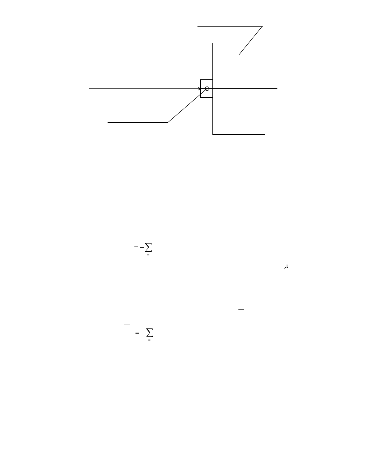
2) fasten the dosimeter on the phantom so that “This side to body” inscription faces
the phantom. Place the dosimeter with phantom onto the verification dosimetric unit so that
the normal line from the geometrical center of phantom’s front wall coincides with the
central axis of collimator of verification dosimetric unit. Central axis of collimator of
verification dosimetric unit must go through geometrical center of detector of the dosimeter
being tested, figure 5.1. Geometrical center of detector is stated in the dosimeter’s
Operation Manual;
Page 29
29
3) calculate an average value of measured gamma radiation ambient background
DER (further – gamma background) when there is no reference radiation source. To do it,
wait no less than 600 s from the moment the instrument was placed on the dosimetric
equipment and then take 5 DER measurement readings at 150 s interval (no less). Then
calculate average DER meaning of gamma background
b
H
.
, by formula (5.1). One
segment of analogue scale must be indicated.
5
1
..
5
1
i
bib
HH
, (5.1)
where
bi
H
.
– i-th meaning of gamma background DER measurement, Sv/h;
4) move the dosimeter on the dosimetric unit so that geometrical center of the
detector coincides with the reference point, where reference DER value is 3,0 μSv/h, and
expose the dosimeter to irradiation. At that two segments of analogue scale must be
indicated;
5) wait at least 100 s after exposure starts, then take 5 DER measurement readings
(at 60 s interval at least). Then calculate average DER value
j
H
.
by formula
5
1
..
5
1
i
jij
HH
, (5.2)
where
ji
H
.
– i-th dosimeter reading when measuring DER in j-th tested point;
6) repeat measurements for points where reference DER value is 80,0; 800 μSv/h.
At that three segments of analogue scale must be indicated if DER is 80,0 μSv/h and four
segments if DER is 800 μSv/h;
7) move the dosimeter on the dosimetric unit so that geometrical center of the
detector coincides with the reference point, where reference DER value is 8,0 mSv/h;
8) expose the dosimeter to irradiation, at that five segments of analogue scale must
be indicated;
9) wait at least 60 s after exposure start, then take 5 DER measurement readings
(at 20 s interval at least) and then calculate average DER value by
j
H
.
by formula (5.2);
10) repeat the measurement for the reference point where reference DER value is
80 mSv/h. At that six segments of analogue scale must be indicated;
Phantom
Irradiation direction
Detector geometrical center
Figure 5.1 – The way for dosimeter with phantom be placed on the verification
dosimetric unit
Page 30
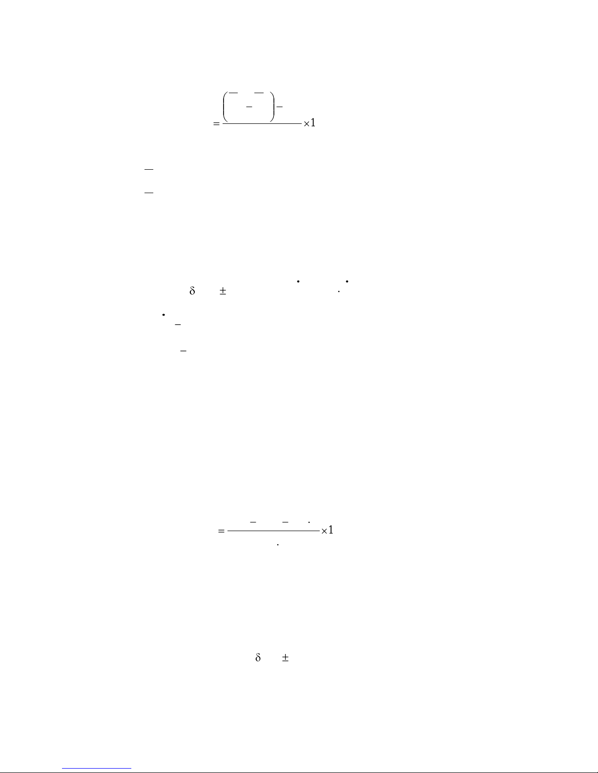
30
11) when using РМ1621А, РМ1621МА dosimeters: repeat measurements
according to article 9) for the reference point where reference DER value is 800,0 mSv/h.
At that seven segments of analogue scale must be indicated;
12) calculate relative measurement error Qj, %, by formula
100
.
...
oj
oj
bj
H
HHH
Q
, (5.3)
where
oj
H
.
– reference DER value in the tested point;
j
H
.
– average DER value in the tested point;
b
H
.
– average DER value of gamma background in μSv/h equal to 3,0; 80,0
and 800,0 μSv/h and average DER value of gamma background in mSv/h when reference
DER is 8,0; 80,0 и 800,0 mSv/h;
13) Verification results are considered positive, if DER measurement error results
for all tested points, Qj, don’t exceed error Q
add
, calculated by formula 5.4.
add
= (10 + 0,0015/H+ 0,01H) %, (5.4)
where H DER value, mSv/h;
0,0015 – coefficient, mSv/h;
0,01 coefficient, (mSv/h)-1.
5.7.3.2 DE measurement main relative measurement error is calculated as follows:
1) set maximum DER and DE threshold levels on the dosimeter and switch on DE
measurement mode;
2) do actions described in 5.7.3.1.(2);
3) read initial DE value from the dosimeter;
4) move the dosimeter on the dosimetric unit so that geometrical center of the
detector coincides with the reference point, where reference DER value from the reference
gamma source
137
Cs is 3,0 μSv/h, and irradiate the dosimeters during T time equal to
60 min;
5) read end DE value from the dosimeter when irradiation is over;
6) calculate main relative DE measurement error Qj, in percents, by formula
100
)(
.
.
TH
THHH
Q
oj
oj
Hjkj
j
, (5.5)
where Нкj – end DE value, mSv;
Н
нj
– initial DE value, mSv;
oj
H
.
– reference DER value in the tested point, mSv/h;
Т – irradiation time in hours.
7) repeat measurements (1-6) for the reference point, at DER value equal to
80,0 mSv/h during T time equal to 30 min;
8) Verification results are considered positive, if DE measurement error results for
all tested points, Qj, don’t exceed
add
= 15%.
Page 31

31
6 STORAGE AND SHIPPING
6.1 Dosimeters in package may be shipped by any kinds of closed transport at the
air temperature from -50 to +50 C.
6.2 Dosimeters in package should be arranged and fastened in the transport so that
their stable position is ensured and shocks are avoided.
6.3 When carried by sea, Dosimeters in package should be placed in hermetic
plastic bags with silica gel.
6.4 When carried by air, Dosimeters in package should be placed in hermetic
compartments.
6.5 Dosimeters should be stored in the manufacturer’s package at the air
temperature from -15 to +50 C and air relative humidity up to 95 % at a temperature of
35 C.
6.6 Dosimeters without package are to be stored at the air temperature from 10 to
35 C and relative humidity up to 80 % at a temperature of 25 C.
6.7 The storage place should be free of dust, vapors of strong chemicals,
aggressive gases and other substances that may cause corrosion.
Page 32

32
7 WARRANTY
7.1 The manufacturer guarantees that the Dosimeter meets the requirements of
Technical Specification provided that the customer will observe the guidelines of its use,
shipping and storage described in this manual.
7.2 The warranty period of use is 18 months from the date of sale (placing the
Dosimeter in service).
7.3 The warranty period of storage is 6 months since the date of acceptance of the
Dosimeter by the officer of the Quality Control Department of the manufacturer.
7.4 Warranty and after-warranty repair is carried out by the manufacturer or the
institutions that have a permission of the manufacturer.
7.5 Warranty does not cover the Dosimeters:
- without the operating manual;
- in case of their unauthorized opening;
- with mechanical damages;
- if the requirements of exploitation and storage were not satisfied;
- after expiration of the warranty period stated in article 7.2.
7.6 The warranty period of use is prolonged for a period of warranty repair.
7.7 Warranty does not cover the battery. The battery replacement is not considered
as the warranty repair.
Page 33
33
ATTACHMENT A
(reference)
Typical instrument anisotropy
(data are normalized to the calibration direction 0o)
Figure A.1 – for horizontal installation at the phantom (rotation in vertical plane):
1 –
241
Am (59,5 keV); 2 –
137
Cs (662 keV); 3 – 60Co (1250 keV)
Figure A.2 – for vertical installation at the phantom (rotation in horizontal plane):
1 –
241
Am (59,5 keV); 2 –
137
Cs (662 keV); 3 – 60Co (1250 keV)
Page 34
34
ATTACHMENT B
(reference)
DIAGRAM OF DOSIMETER ROTATION TO MEASURE ANGULAR RESPONSE
Figure B.1 – Diagram of dosimeter rotation in horizontal plane
Figure B.2 – Diagram of dosimeter rotation in vertical plane
Page 35
35
ATTACHMENT C
(reference)
OVERALL DIMENSIONS, EFFECTIVE CENTER OF THE DOSIMETER DETECTOR
Figure C.1
 Loading...