

Page 1

G
4
Radio Installation Manual
Polhemus
40 Hercules Drive
PO Box 560
Colchester, VT 05446-0560
Tel: 802-655-3159
Fax: 802-655-1439
URM10PH234
REV A
AUG 2010
Page 2
Introduction
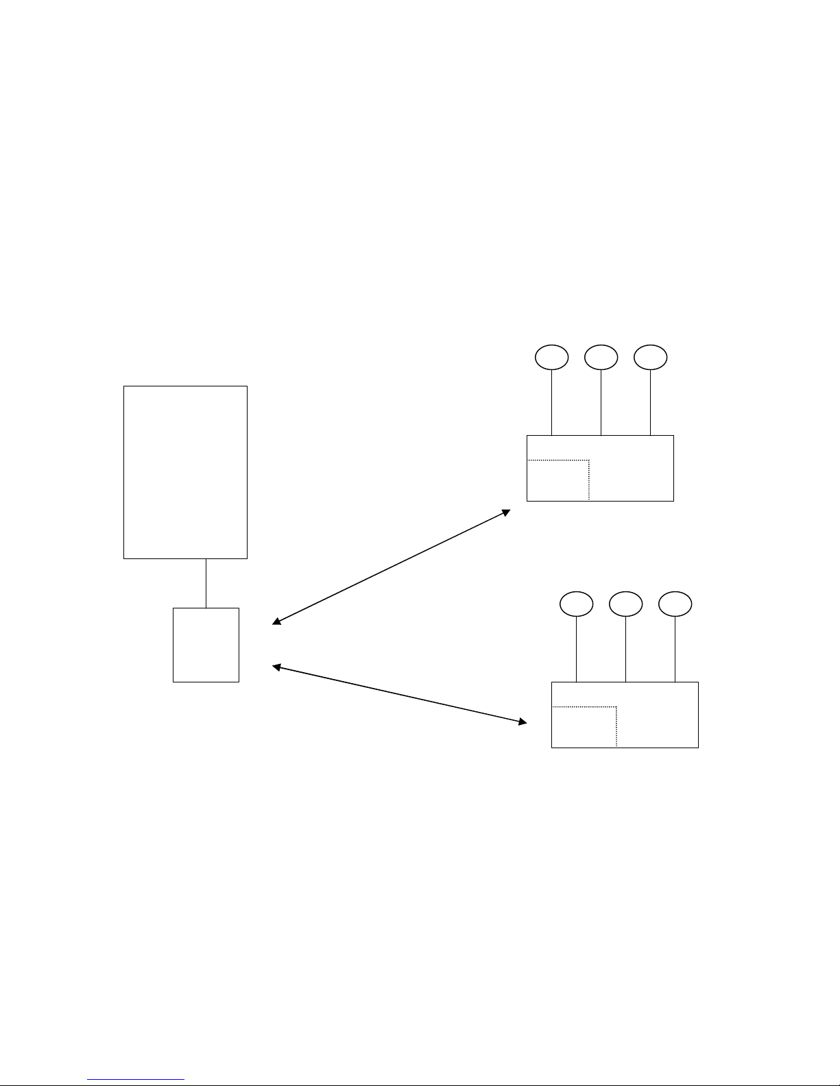
The G4 radio link is a 2.4 GHz Spread Spectrum system consisting of one or more data
collecting HUB devices that each have their own RF transceiver module and a common
USB dongle radio module that attaches to a host computer. The user can use Polhemus
provided software to operate the system or develop their own custom software
applications using Polhemus provided SDK for Windows or LINUX. A simple block
diagram of the system is shown below.
Magnetic Sensors
Host
Computer
RF
Module
USB
Dongle
2.4
GHz
RF link
G4 system
G4
RF
Module
HUB
Magnetic Sensors
G4
RF
Module
HUB
The user is required to do a one time set-up to associate the USB dongle with the HUB
devices. Once that is done the system connects automatically and there is no need for
user intervention to operate the RF system.
URM10PH234 REV A AUG 20101
Page 3
Preparing the system
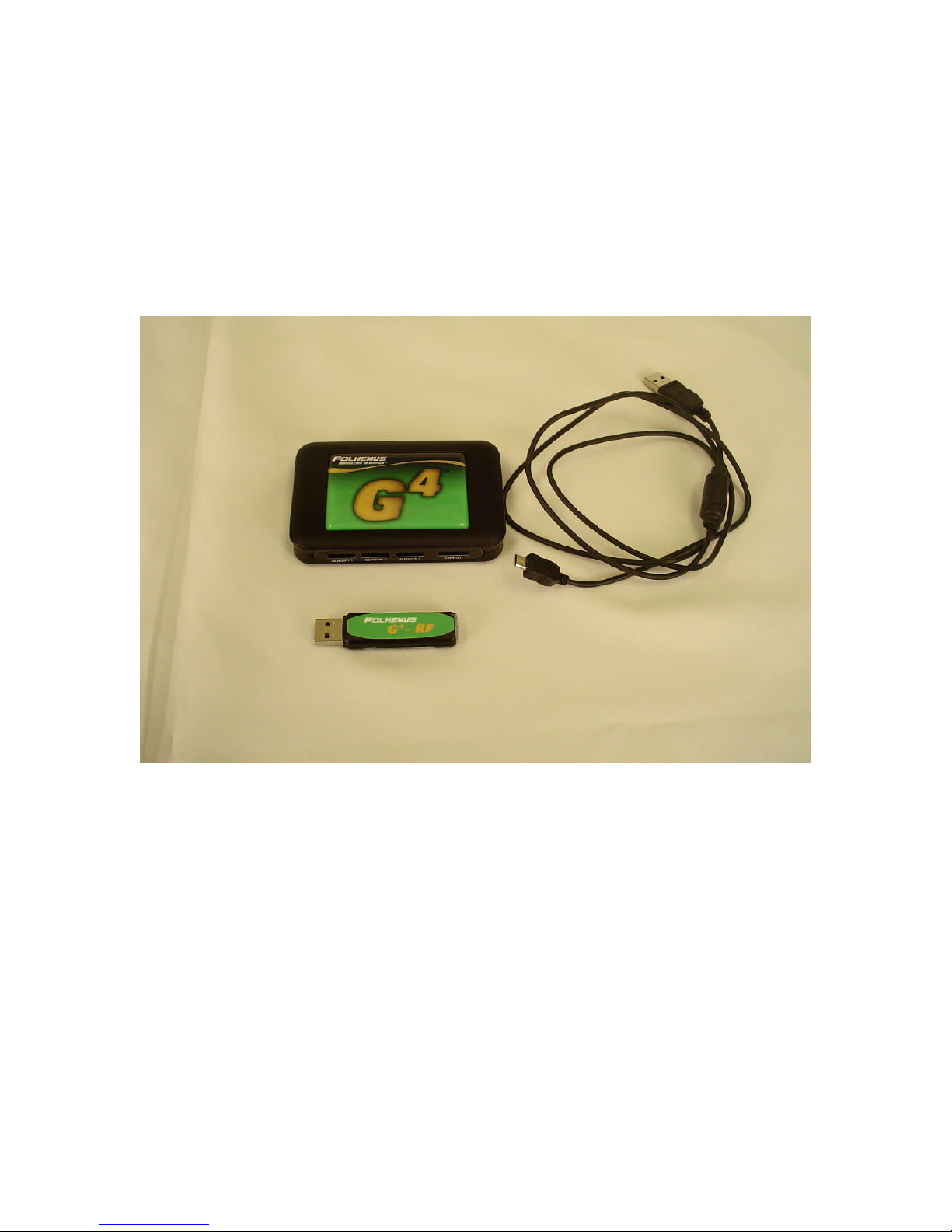
To prepare the system you will need the Hub or Hubs, the USB dongle and a USB cable
(provided with the system). You must also have a host computer available with the
configuration software provided on the CD that came with the G4 system loaded on the
host computer. When you place the CD in the host computer the installation program
will automatically run. Follow the instructions to load all the required software
components.
The diagram below shows the connection ports, switch and LED indicators on the Hub.
All that is required for the RF setup is a USB cable. There is no need to have any sensors
plugged in for the initial setup. The battery in the hub is charged via the USB cable so
allow at least 30 minutes of charging time to ensure you can complete the set-up and test
the system before needing to charge the battery again. The G4 Hub had 3 sensor ports for
connecting magnetic sensing devices. It has a digital I/O port that is user configurable for
us to 8 separate digital inputs. A USB connection is used for charging the Hub battery
and configuring the HUB. It can also be used in areas of heavy RF interference to bypass
the RF link and send the data directly to the USB port. Four blue indicators are used to
display the RF signal strength.
URM10PH234 REV A AUG 20102
Page 4
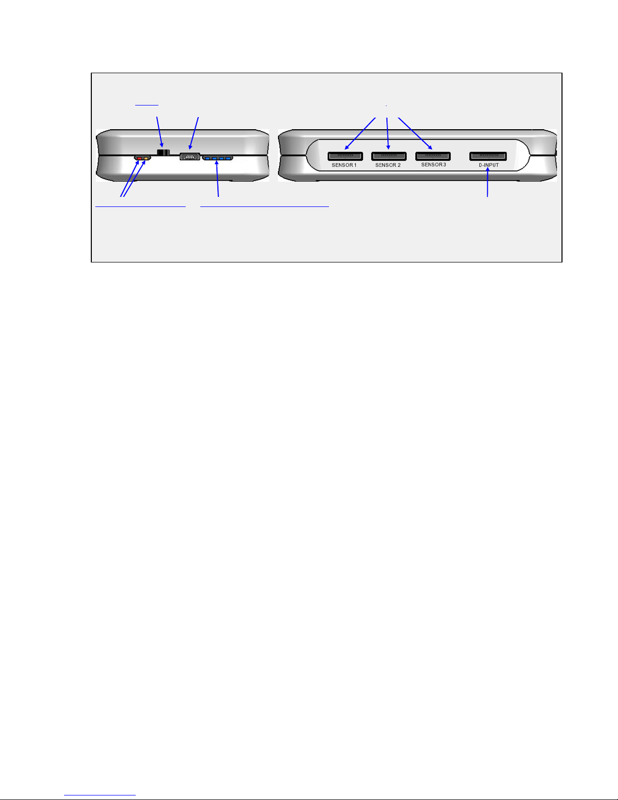
Power
OFFON
4 Lights = Strongest
Red = Low
USB
Sensor Ports
Digital Accessory Port
T
OP
S
IDE
Battery Status Indicators
Orange = Charging
RF Signal Strength Indicators (Blue)
Strobing = Searching
The next sections will describe how to set up the radio sytem. Polhemus has provided
configuration software that walks the user thhough the set up process step by step. Two
software versions are available: one for Windows™ and one for LINUX™.
URM10PH234 REV A AUG 20103
Page 5
Windows Setup
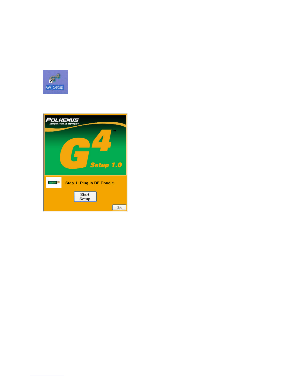
Install the G4 host software from the CD provided with the system. After installation
click on the G4 configuration icon located on the desk top.
The following screen will appear:
Plug in the RF dongle to an available USB port on the host computer. The found new
hardware ICON will appear and a request for you to load the USB driver. Click the
button that loads the drivers automatically. Press the Start Setup button. The following
screen will appear. Note in this screen example a generic serial number is shown. The
factory serial number will be shown on an actual setup.
URM10PH234 REV A AUG 20104
Page 6
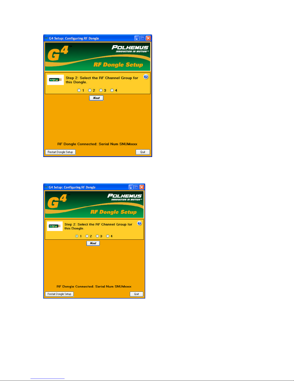
You have your choice of one of four RF channel groups. This allows the user to attempt
different RF channels in case of interference. In this case channel 1 is chosen.
Click on the next button. The follow screen appears
URM10PH234 REV A AUG 20105
Page 7
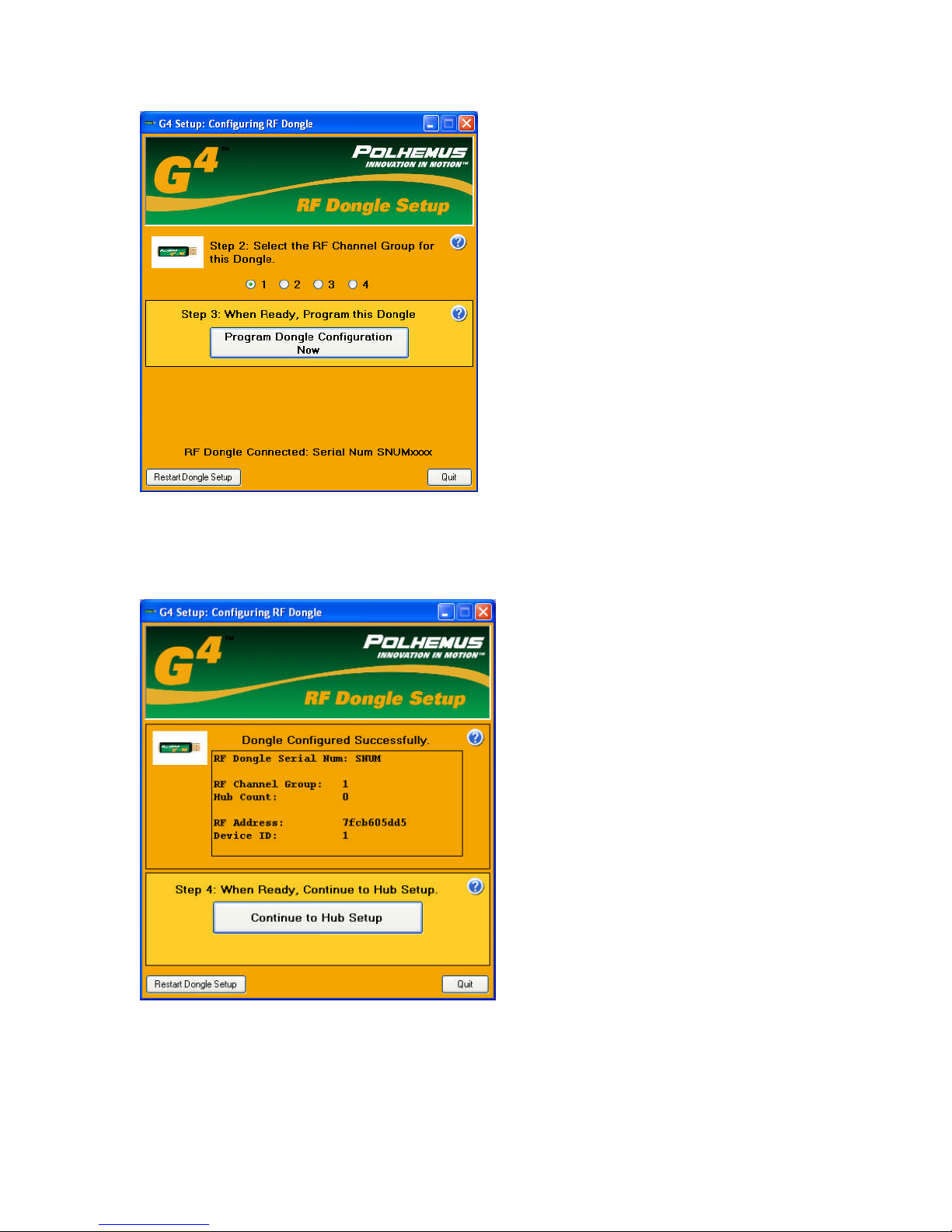
Press “Program Dongle Configuration Now”
The following screen will appear
A random RF address will be generated that will provide a unique identifier to the USB
Dongle.
URM10PH234 REV A AUG 20106
Page 8
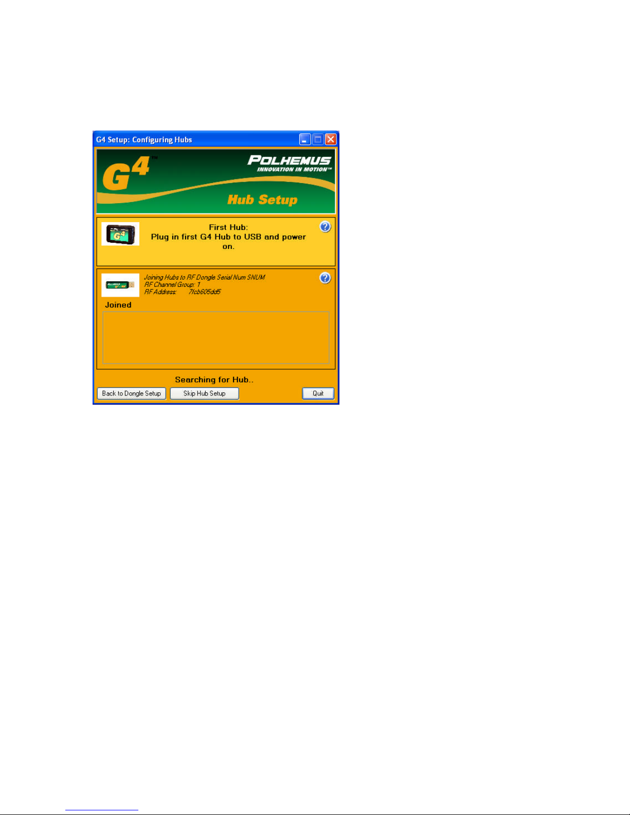
The next step is to associate the Hubs to the RF dongle. Up to 255 hubs can be
associated to a dongle. Click on the “Continue to Hub Setup” button. The following
screen will appear.
Using the USB cable provided with the system plug one end into the G4 Hub and the
other end a USB port on the Host computer. Turn the HUB on by sliding the power
switch on the side.
The hub will be discovered by the host computer and the following screen will appear.
Again a generic serial number is shown in this example instead of the factory serial
number.
URM10PH234 REV A AUG 20107
Page 9
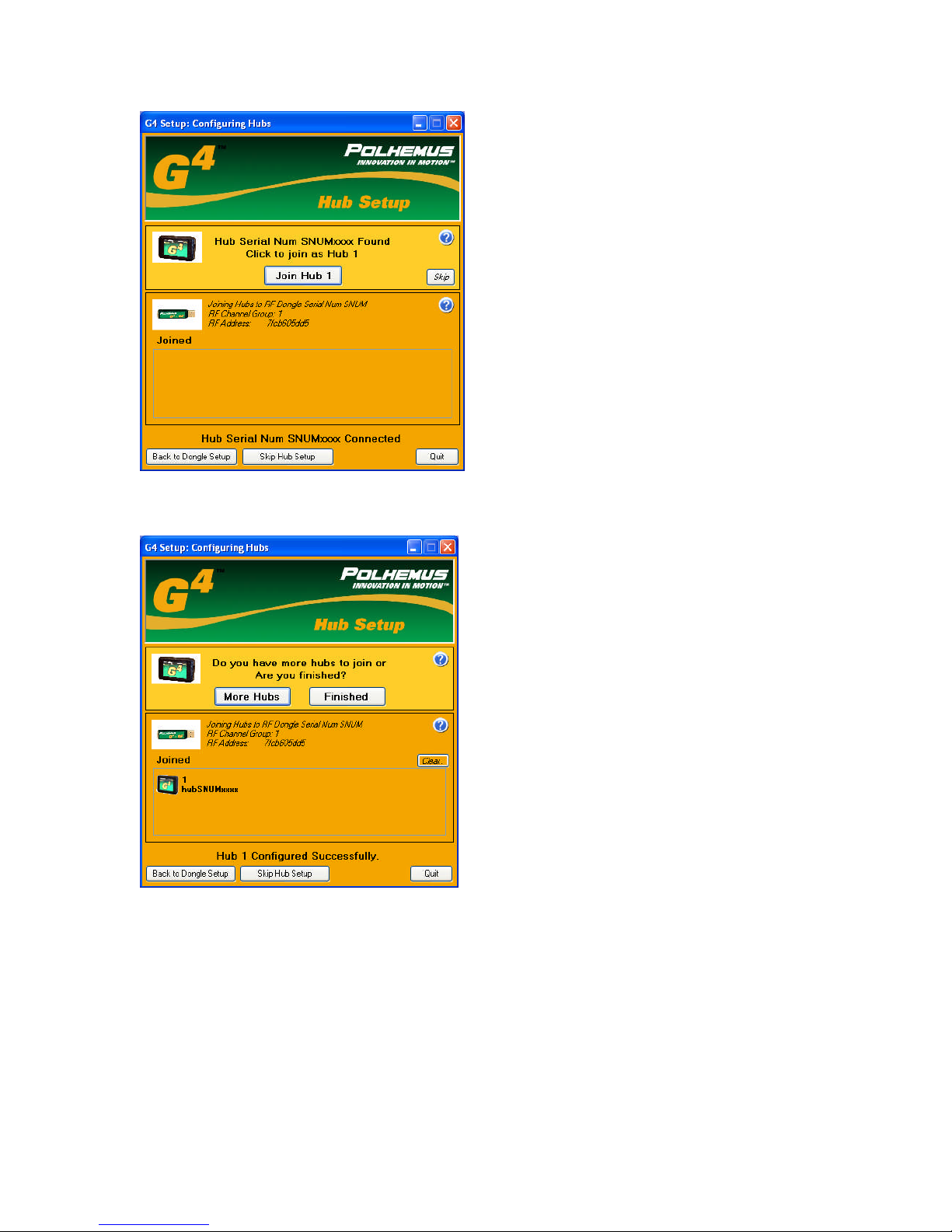
Press the Join Hub 1 button. The following screen will appear.
You can now click on the More Hubs button to continue joining more hubs to the RF
dongle or click on Finished. If you join more hubs, disconnect the first hub from the host
computers USB port and plug in the next hub and join it. You will get a screen similar to
the one below.
URM10PH234 REV A AUG 20108
Page 10
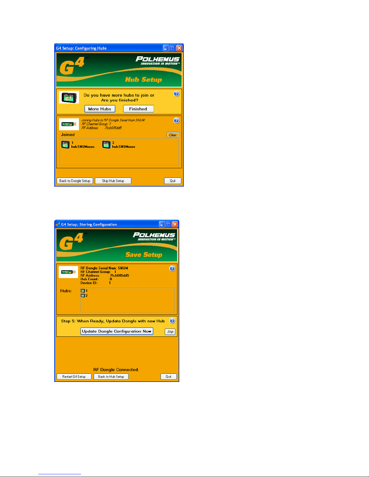
Every time you join a hub it will appear in the lower window. Once you have joined all
the hubs click the finished button. You will get the following window.
In the above example two Hubs have been joined. You can now disconnect the USB
cable and turn off the HUB. Insert the RF Dongle back into the host computer and click
“Update Dongle Configuration Now” to update the dongle with the Hub information.
URM10PH234 REV A AUG 20109
Page 11
Now the system is ready to test. Plug one of the Polhemus sensors provided in the
system. Ensure the Dongle is connected to a USB port on the host computer. Power on
the G4 hub by turning on the power switch. The Blue LED indicators will blink several
times and then go solid. The more indicators lit, the higher the signal strength. Once the
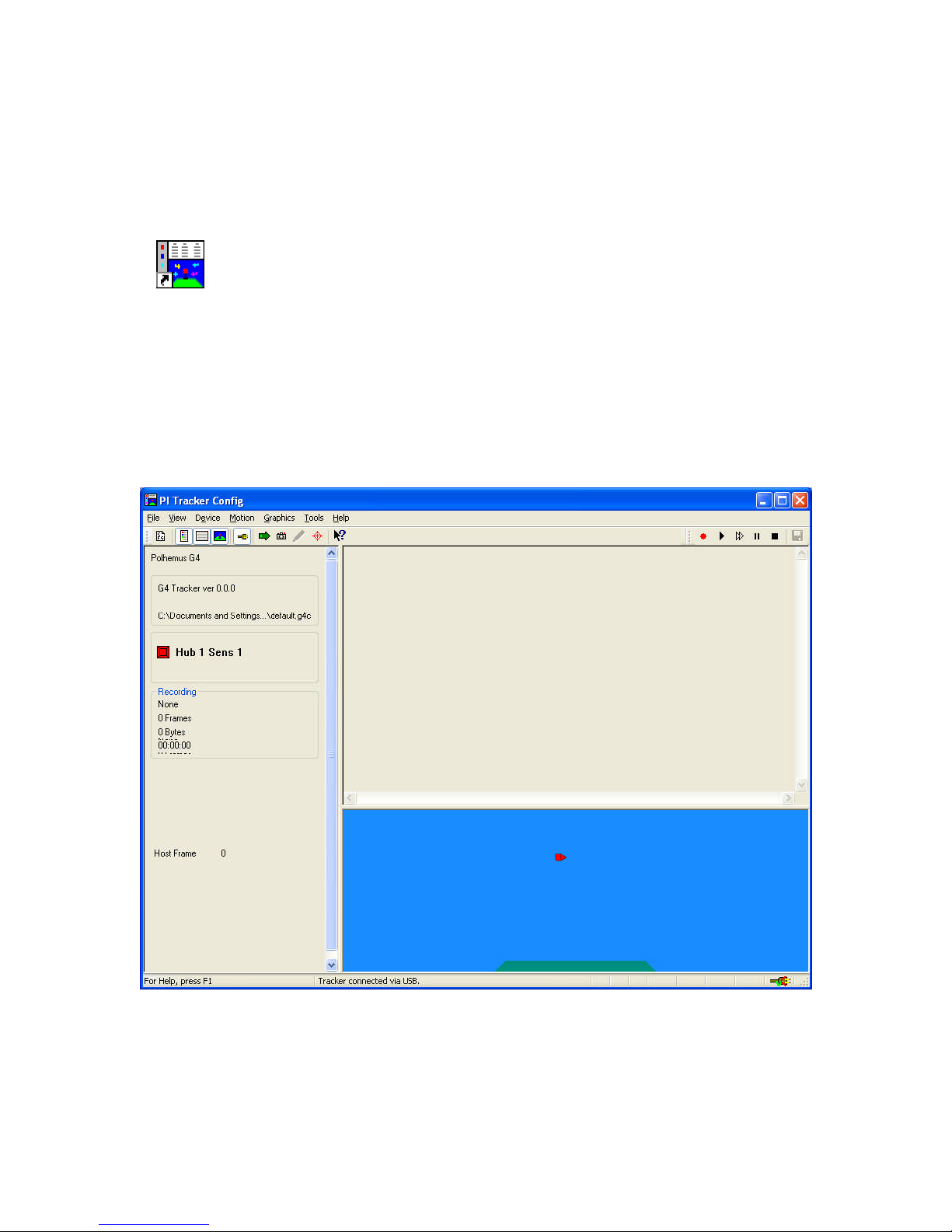
system finishes this initialization, click on the PImgr link on the host computer Desktop.
Pimgr.lnk
The following screen will appear showing the number of active Hubs and the number of
sensors active on each hub. The system is operational now and the PIMgr software can be
used to collect data or the user can commence writing their own software using the
Polhemus provided SDK.
URM10PH234 REV A AUG 201010
Page 12
LINUX Setup
The RF configuration program is self explanatory and walks you through the set-up of the
G4 radio system. This section will give the user guidance on how that program
functions.
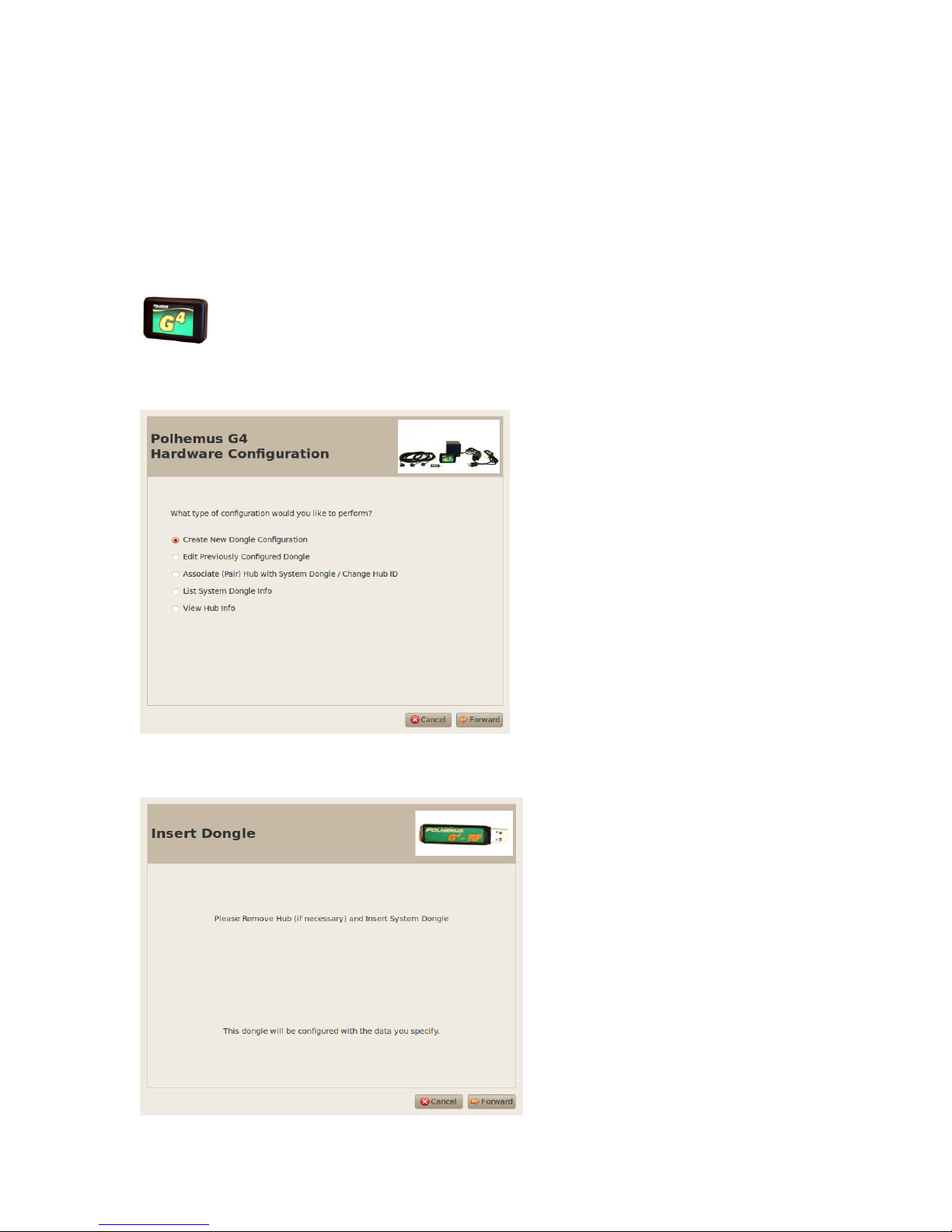
Start by clicking on the RF configuration program Icon
You will get the following window:
Click the “Create New Dongle Configuration” button and then click “Forward”
You will get the following window:
URM10PH234 REV A AUG 201011
Page 13
Follow the instructions on the screen and then click forward to the next screen:
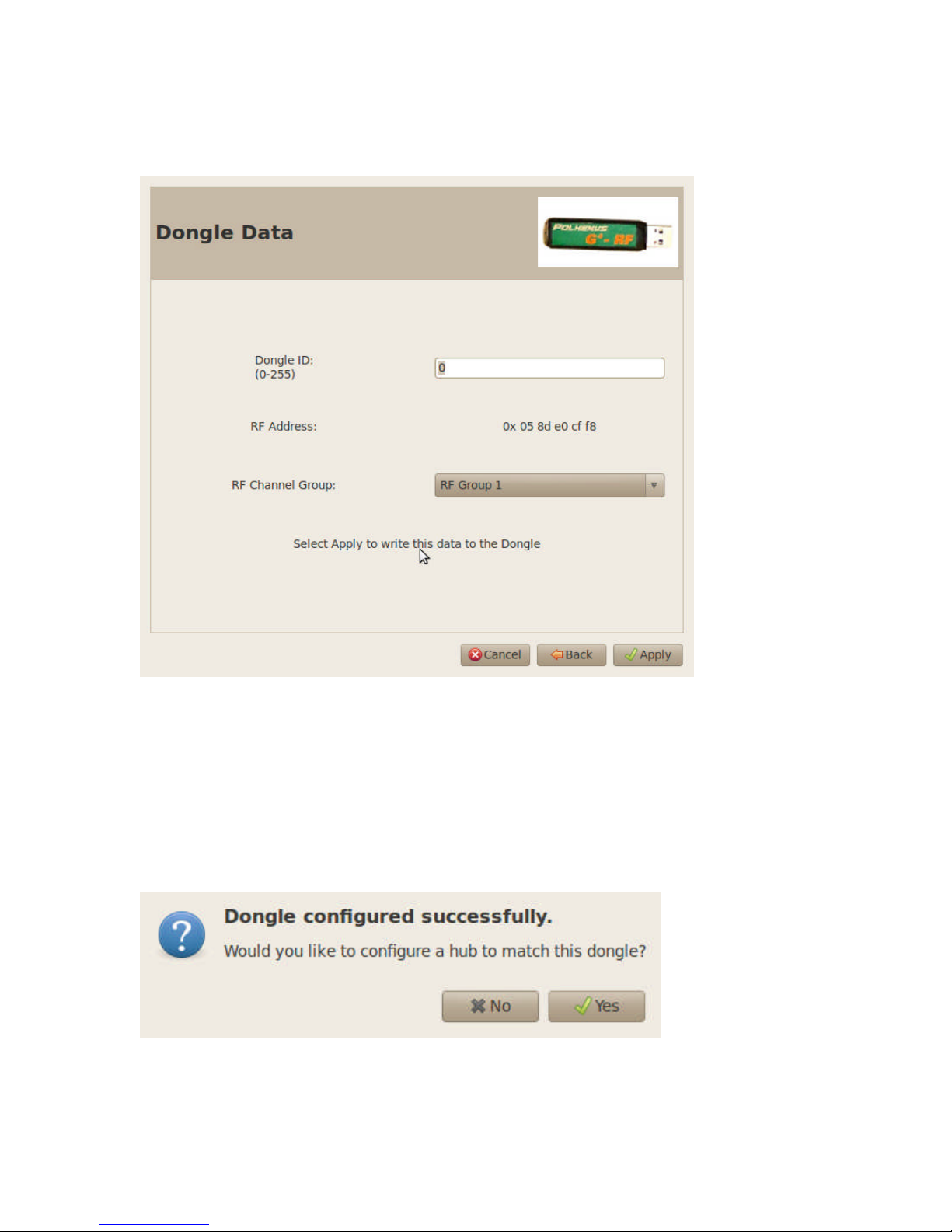
At this point you can give the Hub a unique ID number. Data from this Dongle will be
labeled with this ID. A random RF address is created for this dongle to uniquely identify
it when the dongle is associated to a hub. Finally one of four RF groups can be selected.
This allows the user to shift frequency band in the case of interference. When done
making the desired selections click the apply button. You will then get the following
window:
Press Yes to receive the following Window:
URM10PH234 REV A AUG 201012
Page 14
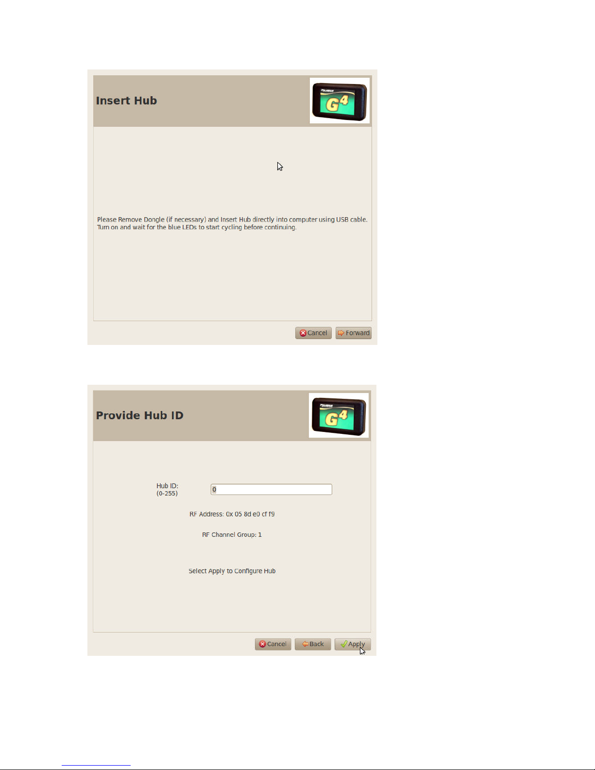
Follow the instructions on the screen and the click Forward to get the following screen:
Provide an ID for the Hub. Since multiple Hubs can be associate to the same RF dongle
this ID will uniquely identify the data. After choosing an ID click apply.
URM10PH234 REV A AUG 201013
Page 15
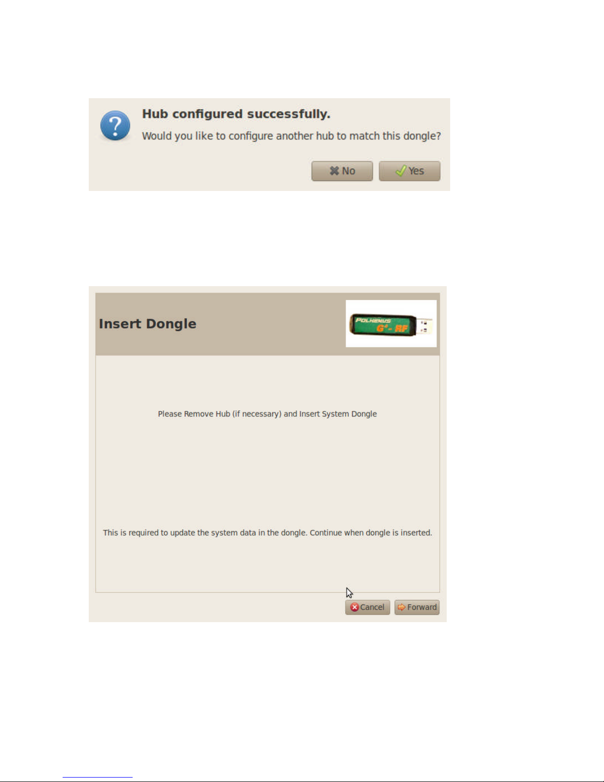
You will get the following Window.
Click yes if you have more Hubs to configure. Be sure to give each Hub a unique ID
number. When done configuring all the Hubs, click no. You will get the following
Window:
This next step updates the user HUB configuration in the RF dongle. Follow the
instructions on the screen and click forward. The setup is now complete and you will
get the following screen:
URM10PH234 REV A AUG 201014
Page 16
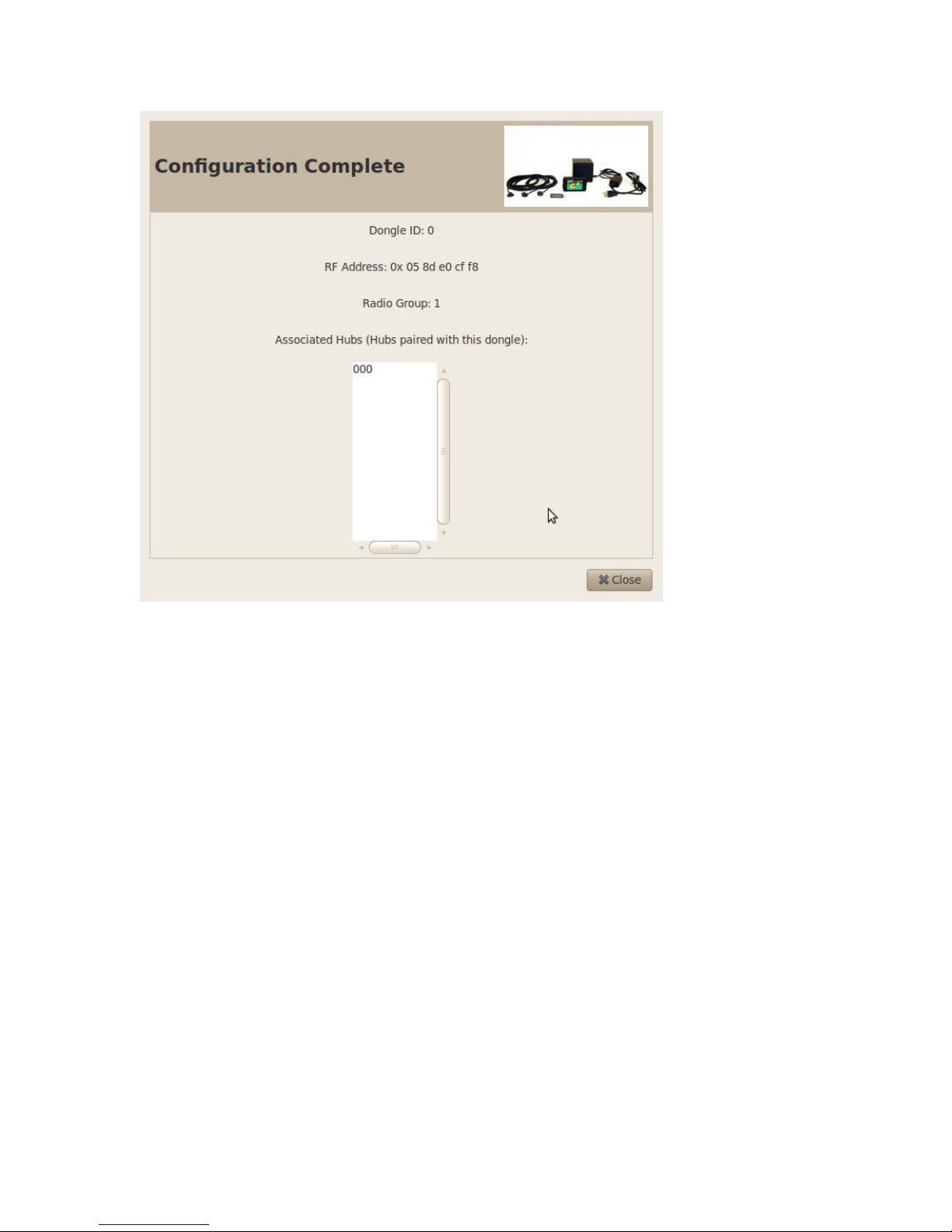
The system is now ready for testing. Plug the USB dongle into the Host computer.
Connect 1 to 3 sensors to each HUB to be tested. Turn on the HUB devices. The Blue
LED indicators will blink and then go solid. If the signal is weak as indicated by the blue
LED array, try using a USB extension cable to move the RF dongle away from the host
computer. Next start the G$ terminal application provided by Polhemus. You will get a
screen like the one below.
URM10PH234 REV A AUG 201015
Page 17
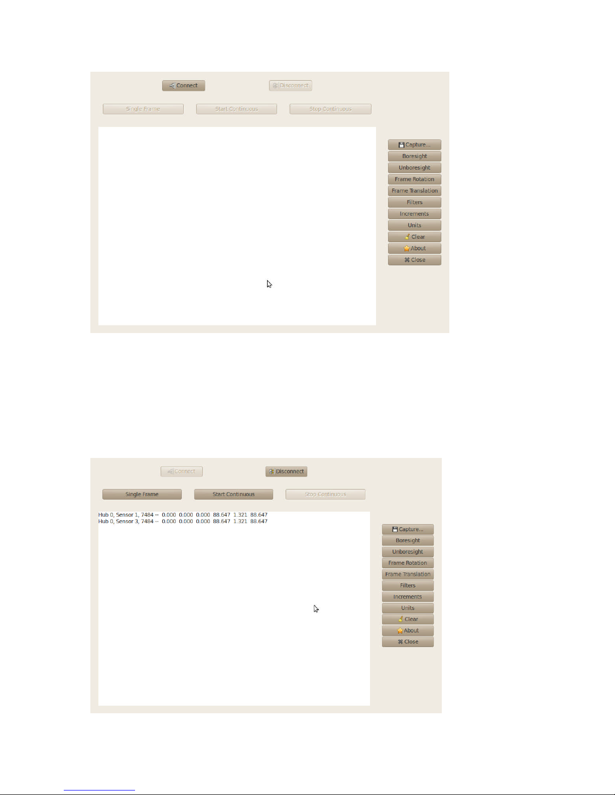
Press the connect button to connect the Hub to the host computer. Once connected the
connect button will shade and the disconnect button will be highlighted. You can now
press the “Single Frame” button and data will be displayed like shown below: In this
example only one Hub is present with 2 sensors connected. At this point this system is
set-up and functional.
URM10PH234 REV A AUG 201016
Page 18
Regulatory Information
Caution: Any changes or modifications not expressly approved by the party responsible
for compliance could void the user's authority to operate the equipment.
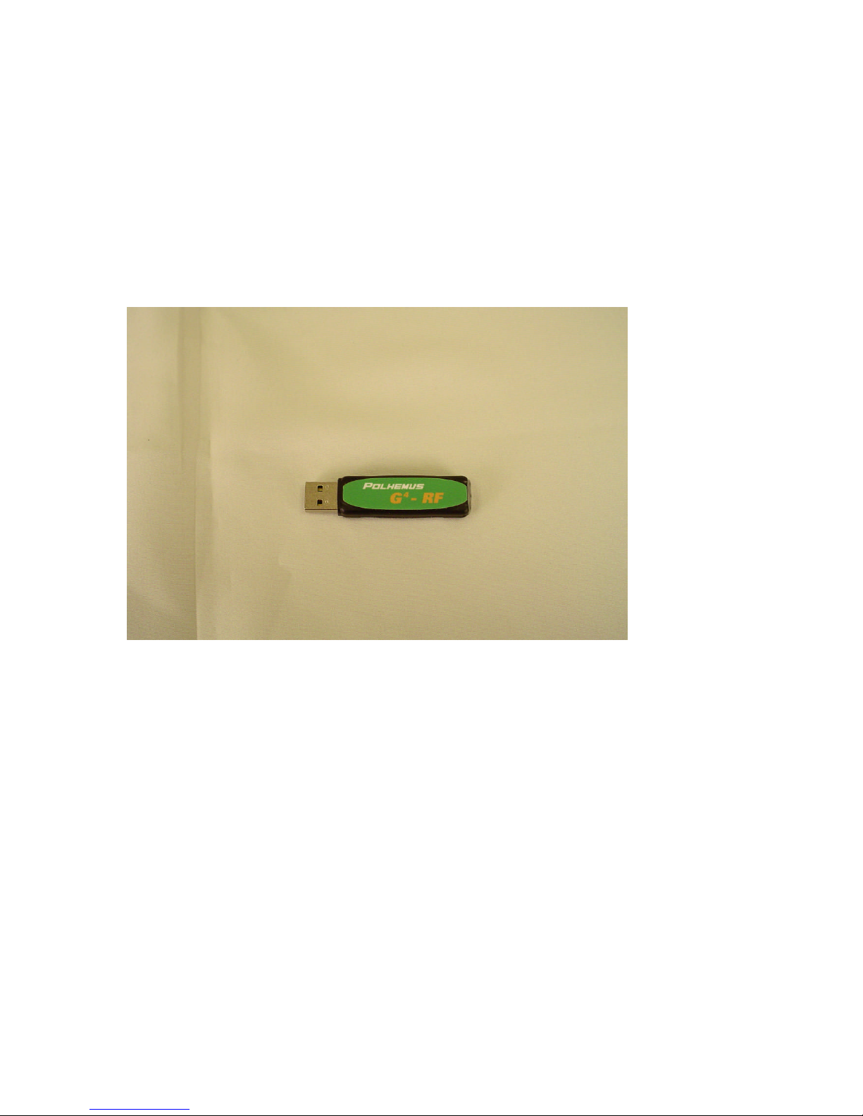
RF Dongle
FCC ID YJUG4USB01
IC: 9183A-G4USB01
Polhemus G4 RF Dongle
This device complies with Part 15 of the FCC Rules. Operation is subject to the following
two conditions: (1) this device may not cause harmful interference and (2) this device
must accept any interference received, including interference that may cause undesired
operation
URM10PH234 REV A AUG 201017
Page 19
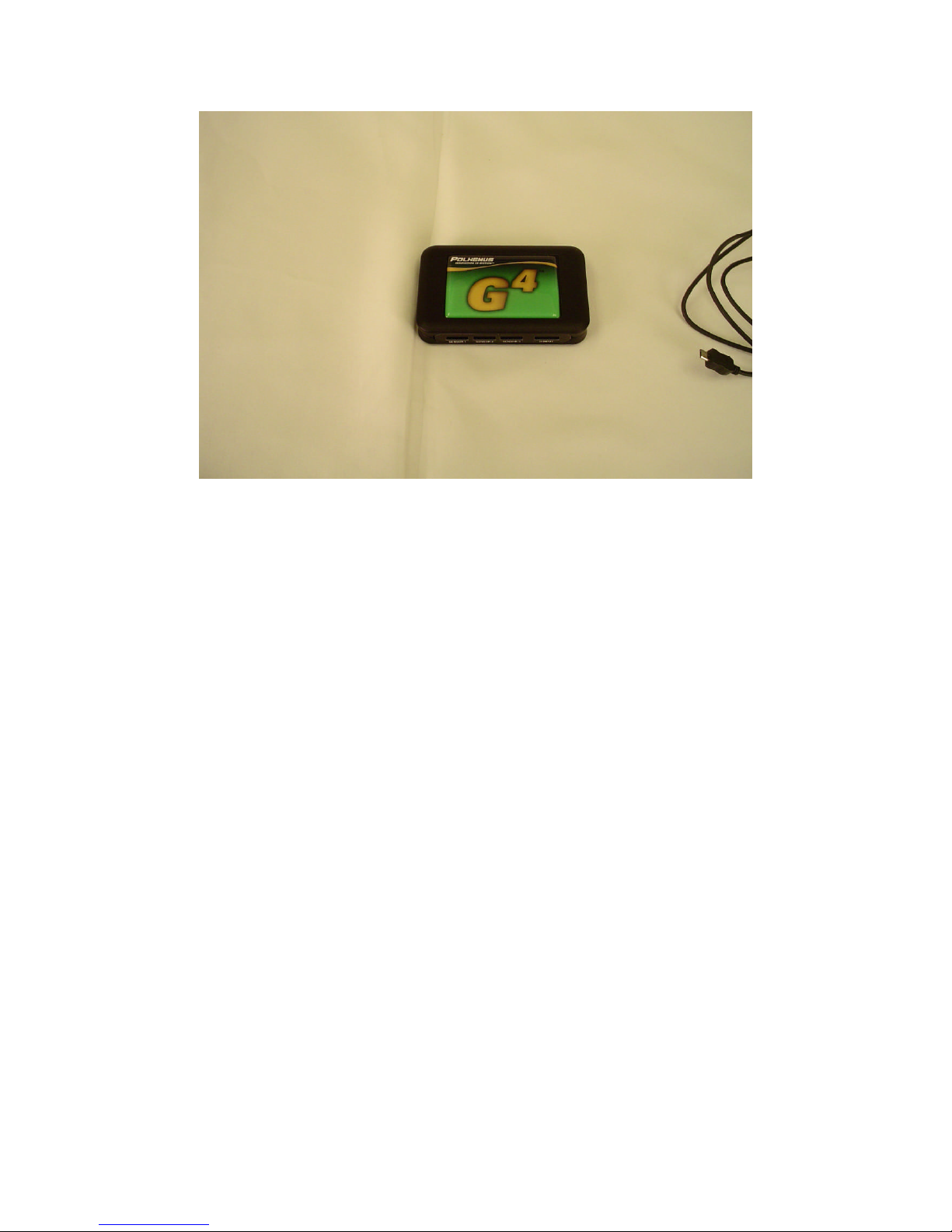
FCC ID YJUG4HUB01
IC: 9183A-G4HUB01
Polhemus G4 Hub
This device complies with Part 15 of the FCC Rules. Operation is subject to the following
two conditions: (1) this device may not cause harmful interference and (2) this device
must accept any interference received, including interference that may cause undesired
operation
Note: This equipment has been tested and found to comply with the limits for a Class B digital device,
pursuant to part 15 of the FCC Rules. These limits are designed to provide reasonable protection against
harmful interference in a residential installation. This equipment generates, uses and can radiate radio
frequency energy and, if not installed and used in accordance with the instructions, may cause harmful
interference to radio communications. However, there is no guarantee that interference will not occur in a
particular installation. If this equipment does cause harmful interference to radio or television reception,
which can be determined by turning the equipment off and on, the user is encouraged to try to correct the
interference by one or more of the following measures:
—Reorient or relocate the receiving antenna.
—Increase the separation between the equipment and receiver.
—Connect the equipment into an outlet on a circuit different from that to which the receiver is connected.
—Consult the dealer or an experienced radio/TV technician for help.
URM10PH234 REV A AUG 201018
Page 20

URM10PH234 REV A AUG 201019
 Loading...