

Polatrak Deep C Meter 300 AD Operation Manual

Corrosion testing probes
Deep C Meter 300 AD™
ROV-mounted CP probe
Operation manual
ROV-interfaced
cathodic protection
monitoring system
Deepwater Corrosion Services Inc.
©
2015 Deepwater C orrosion Servic es Inc. Specications subject to change without notice
Can output both
contact and EFG
probe readings
|
13813 FM 529 Rd, Houston, TX 77041 USA
Digital output
RS232 standard
ASCII string
+1 (713) 983 7117
|
Email: sales@stoprust.com
No batteries;
ROV 24V DC
powered
|
polatrak.com
SMB-001 Deep C Meter 300 AD Manual

Deep C Meter 300 AD™ operation manual
Table of contents
1 Overview 3
2 Documentation 4
3 Health and safety 4
4 LED readout components 5
4.1 Deep C Meter 300 AD™ 5
4.2 Articulating mount 6
4.3 Flying leads 6
5 Probe unit components 7
6 ROV interface 8
7 Calibration 8
7.1 Deep C Meter AD calibration 8
7.2 Bucket calibration 9
7.3 Subsea calibrations 9
7.4 Online calibration 9
8 Operation 10
8.1 Mounting on ROV 10
9 Taking CP potential readings 11
10 Data interpretation 11
10.1 Removal from ROV 11
11 Maintenance and repair 12
11.1 Tip replacement 12
11.2 Electrode element replacement 12
12 RS232 functions 13
12.1 Data output 13
12.2 Control data input 13
13 Troubleshooting 14
13.1 General 14
14 Spare parts and accessories 15
List of gures
Figure 1 - Overview 3
Figure 2 – Rear of pressure housing 5
Figure 3 – Front of pressure housing 5
Figure 4 - Meter mount 6
Figure 5 - Flying leads 6
Figure 6 - SEA CON® RMG-3FS wiring diagram 12
Figure 7 - Calibration vs. zinc coupon 16
www.polatrak.com
©
2015 Deepwater C orrosion Servic es Inc. Specications subject to change without notice
|
13813 FM 529 Rd, Houston, TX 77041 USA
|
Telephone: +1 (713) 983 7117
2 SMB-001 Deep C Meter 300 AD Manual
|
Email: sales@stoprust.com
Deep C Meter 300 AD™ operation manual
List of tables
Table 1 - ROV interface pin outs 8
Table 2 - CP equipment pin outs 7
Table 3 - Normal cathodic protection ranges for bare carbon steel in seawater 10
Table 4 - RS232 Communication settings 12
Table 5 - RS232 Command list 13
Table 6 - Troubleshooting quick guide 14
Table 7 - List of spare parts 15
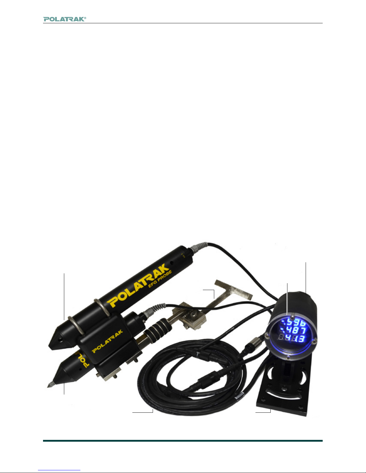
1. Overview
The Deep C Meter 300 AD is a complete ROV-interfaced cathodic protection monitoring system.
The system comprises ve basic parts:
1.1 LED readout
Triple voltmeters housed in a Delrin pressure housing.
1.2 Contact probe
Twin element, tip contact CP probe (Polatrak® Model ROV-II™).
1.3 Flying lead
Three-meter-long umbilical that connects the probe to the readout.
1.4 Power whip
Two-meter-long umbilical that interfaces with the ROV for power and data output.
1.5 EFG probe (optional)
Can be added as an upgrade to the standard package.
EFG probe
(optional)
ROV-II
™
contact
probe
Flying
lead
ROV-II
™
T-handle
mount
Power lead
(attaches to
rear of display)
LED
readout
Mount
Figure 1: Deep C Meter 300 AD™ components
www.polatrak.com
©
2015 Deepwater C orrosion Servic es Inc. Specications subject to change without notice
|
13813 FM 529 Rd, Houston, TX 77041 USA
|
Telephone: +1 (713) 983 7117
3 SMB-001 Deep C Meter 300 AD Manual
|
Email: sales@stoprust.com

1.6 The Deep C Meter 300 AD™ has the following upgrades from previous versions:
• Smaller pressure housing
• Combines ROV-II™ and Polatrak EFG pressure housing
• Programmable ultra-bright LED displays with brightness adjustments
• Digital output (RS232 – standard ASCII string)
• ROV 24V DC powered, which eliminates the need to open the pressure housing to change batteries
2. Documentation
The following documents are contained in the appendix:
2.1 ROV-II Operations Manual (354-MN01-ENG)
2.2 EFG 1 Operations Manual (358-MN02-ENG)
2.3 RUSS Operation Manual (358-MN04-ENG)
2.4 Parker Seals - Parker O Lube MSDS – O-ring lubricant
2.5 Dow Corning – 4 Electrical Insulating Compound MSDS – connector sealant
PLEASE CONTACT YOUR DEEPWATER REPRESENTATIVE FOR ANY QUESTIONS AND/OR
ISSUES REGARDING THIS MANUAL.
Deep C Meter 300 AD™ operation manual
3. Health and safety
It is the intention of Deepwater Corrosion Services that all procedures will be carried out in a safe
manner in accordance with the Health and Safety At Work Act and any other relevant legislation. If
required by the client, Deepwater personnel will attend any site safety induction courses before
carrying out work on site.
www.polatrak.com
©
2015 Deepwater C orrosion Servic es Inc. Specications subject to change without notice
|
13813 FM 529 Rd, Houston, TX 77041 USA
|
Telephone: +1 (713) 983 7117
4 SMB-001 Deep C Meter 300 AD Manual
|
Email: sales@stoprust.com

Deep C Meter 300 AD™ operation manual
4. LED readout components
The readout unit has three major sub-assemblies: The pressure housing, articulated mount and ying leads.
4.1. Deep C Meter 300 AD™
4.1.1. Pressure housing - The pressure housing is made from Delrin and is rated for water
depths of 300 meters (1,000 feet).
4.1.2. Lens - One end of the housing contains an acrylic lens that seals on the pressure housing
with o-rings. Four stainless-steel screws keep the lens seated in the pressure housing. Access
to the inside of the pressure housing is gained by pulling the lens. Removing the lens in the eld
should be avoided wherever possible.
4.1.3. Bulkhead connector - The back end of the pressure housing is sealed with three bulkhead
connectors. These connectors thread into the back of the pressure housing and also seal with
o-rings. It should not be necessary to remove these connectors during normal maintenance. Blank
(dummy) plugs are provided and should be in place whenever the mating connector is removed.
4.1.4. Voltmeter module - The digital voltmeter module is located within the pressure housing.
The module contains three independent LED displays. Default factory range is ± 2499 mV DC on
the top two display lines. The lower display line is set to ± 199.9mV DC. The meter is powered by
24VDC nominal power but will function between 8-36VDC.
EFG
ROV-II
Power,
24 VDC
RS232
Figure 2: Front of pressure housing Figure 3: Rear of pressure housing
and
www.polatrak.com
©
2015 Deepwater C orrosion Servic es Inc. Specications subject to change without notice
|
13813 FM 529 Rd, Houston, TX 77041 USA
|
Telephone: +1 (713) 983 7117
5 SMB-001 Deep C Meter 300 AD Manual
|
Email: sales@stoprust.com
 Loading...