

Page 1
5-BUTTON MANUAL / AUTOMATIC
TRANSMISSION REMOTE STARTER
WITH VIRTUAL TACH SYSTEM
(AS PRG-1000 COMPATIBLE)
Notice
The manufacturer will accept no responsibility for any electrical damage resulting from improper installation of the product, be that either
damage to the vehicle itself or to the unit. This unit must be i nstalled by a certified technician using all safety devic es supplied. Please
note that this guide has been written for properly trained Autostart technicians: a certain level of skills and knowledge is therefore
assumed. Please review the installation guide caref ully before beginning any work.
Warning
Before installing the unit, if installing on a vehicle with a manual transmission, test that the OEM Door Switch contacts of the vehicle work
well, and that the Parking Brake system operates properly. If installing on a vehicle with an automatic transmission, test that the vehicle
does not start when the gearshift lever is in the “Drive” position. If it starts in gear, reset the remote starter to manual transmission.
Doc#: 090826 Rev:1.1 - PS-3175E - - YB - Assembled in Canada
PS-3175E
Quick Installation Guide
(For a copy of the complete install guide visit http://www.autostart.ca)
Table of Contents
Entering Programming Mode ................................... 2
Manual or Automatic Transmission ........................ 2
Resetting the Module................................................ 2
Transmitter Programming Procedure ..................... 2
Entering Programming Options .............................. 2
Programming Options .............................................. 3
Bypass ........................................................................ 4
Optional Time Delay Adjustment in Virtual
Tach System .......................................................... 4
Multi-speed Tach Programming .............................. 5
Horn Honk Timing adjustment ................................. 5
Programming the transponder ................................ 8
Supplementary Information ..................................... 9
Fifth Relay Output (2nd IGN, ACC or CRANK) ..... 9
Tach jumper settings ............................................. 9
Testing ...................................................................... 10
Remote-Starting Your Vehicle ............................... 10
Setting Your Vehicle Into Ready Mode ............... 10
Diagnostics via parking lights ............................... 11
Diagnostic table for shutdown. ............................ 11
Diagnostic table for start failure. .......................... 11
EncryptR™ Technology ......................................... 12
P. 12 http://www.autostart.ca Installation Guide
EncryptR™ Technology
Note: EncryptR™ Technology will be launched October 1st 2009.
How to enable EncryptR™ Technology in a vehicle?
1. Use a Polarstart remote starter (PS-3175E or PS-4661-TWE or PS-4461-TWE with software V.5.0 and
up)
2. Use an EncryptR™ Ready iDatalink ADS-TB or ADS-AL-CA module with EncryptR™ enabled software
which can be downloaded from the idatalink website at www.idatalink.com.
3. Set the Remote Starter in “ADS” bypass mode found in Mode 4 of the remote starter installation manual.
4. Set the Remote Starter in “2way Communication” found in Mode 4 of the remote starter installation
manual.
5. Program the remote starter module to the vehicle, as normally done.
6. Program the ADS bypass module to vehicle, as normally done by following the ADS installation guide.
7. Remote start the vehicle once. If the communication is good between the remote starter and the ADS
bypass module, the LED on the bypass module will blink GREEN upon remote starting the vehicle.
8. EncryptR™ Technology is now automatically set and enabled!!!
What can make the encrypted communication fail?
x Replacing the remote starter module
x Factory reseting the remote starter module
How to re-synchronize the encryption?
1. Follow the ADS bypass reset procedure from the ADS installation manual
2. Re-learn bypass to vehicle by following the ADS installation manual
3. Remote start vehicle once
4. EncryptR™ Technology is now automatically set and re-enabled!!!
About synchronization
x Disconnecting the bypass module and remote starting the vehicle without any bypass module connected
will NOT cause the remote starter module and the ADS bypass to be out of synchronization.
x Disconnecting the battery of the vehicle will NOT cause the remote starter module and the ADS bypass
to be out of synchronization.
x Upon remote starting the vehicle; the remote starter communicates with the ADS bypass module thru the
supplied ADS data cable. Since the communication is set in 2 way communication, the remote starter is
waiting for a confirmation back from the ADS bypass module that it acknowledges upon the start
command. If no answer back from the ADS bypass module, the remote starter will wait for the bypass
module answer in order to change the encrypted code.
x The EncryptR™ is now the safest way to prevent theft from stealing vehicles by using the remote starter.
Using the supplied ADS data cable and the EncryptR™ encryption makes the installation safer than ever
and cannot be tampered with by generating the “Out When Running” signal in the ADS data cable to
override the security on the vehicle.
NOTE: In order to qualify, upon completion of the installation, the installer must go on-line to
www.encryptrtechnology.com
and fill out the Limited anti-theft warranty form.
Page 2
Installation Guide http://www.autostart.ca/ P. 11
Valet mode. Make sure the remote car starter is able to properly enter and exit valet mode. When setting the
remote car starter into valet mode, pressing the lock button will lock the doors without activating the starter kill.
(Refer to the user guide for further information on valet mode.)
Idle mode. Make sure the vehicle properly enters and exits idle mode.
Most comebacks are the result of misunderstandings about how a product works o r performs. Take the
time to properly explain all functions and features to the customers before they leave the premises.
Doing this will save time and money.
Diagnostics via parking lights
Diagnostic table for shutdown.
Parking lights flashes Cause
1
x Runtime has expired.
2
x Shutdown by remote.
x Ready mode is activated.
3
x Failed start.
4
x Brake shutdown.
10
x Hood shutdown.
Flash for 30sec
x Panic mode
Flash for 60sec
x Alarm triggered
Diagnostic table for start failure.
Parking lights flashes Cause
1
(Manual transmission
only)
x Ready mode is not activated.
x Tach signal is not learned.
1 slow Î 2 quick
x The system is set to valet mode.
3
(Automatic transmission
only)
x The parking brake is active.
x Yellow loop is connected.
4
x Brake wire is active
6
x A tach signal is detected before Ignition.
10
x Hood wire is active.
Note: The installer can also use the PRG-1000 to diagnose shutdown and remote start failures. Refer to the
PRG-100 manual guide.
P. 2 http://www.autostart.ca Installation Guide
Entering Programming Mode
Using the Hood Pin
Using the Antenna Programming Assistance Button
(A.P.A.B.) (Optional)
x Press and hold the hood pin for 4 seconds. x Make sure the hood is closed.
x Release the hood pin.
The parking lights will turn ON.
x Turn the ignition key to the IGNITION ON (RUN) position.
x While the parking lights are ON, press the hood pin once
more and release immediately.
The parking lights will turn ON and stay ON for 20
seconds.
x Within 5 seconds, press the programming button on the
antenna twice for 1 second each time.
The LED will come ON solid.
x You now have 20 seconds to select one of the sub-
menus.
x You now have 20 seconds to select one of the sub-
menus.
Note: To exit programming mode, close the hood.
Note: To exit programming mode, press on the antenna
button once (the LED will come ON) and release.
Manual or Automatic Transmission
This module may be installed on vehicles with manual or automatic transmissions. It is originally configured for manual
transmissions. If the vehicle you are working on is automatic, it is mandatory to make a few quick and easy modifications before
the unit is connected. In the event that the configuration requires changes afterwards, a complete reset will be
necessary before those changes become effective.
To install this unit in a vehicle with a manual transmission:
1. Make sure the Yellow loop on the PC board is connected.
2. Connect the Orange handbrake wire located on the 12-pin harness to the vehicle handbrake switch.
3. Connect the Blue/White (+) door input OR
the Grey (-) door input wire located on the 12-pin harness to the
vehicle door pin wire, which monitors all the doors of the vehicle (only use 1 of the 2 door trigger inputs).
4. Make sure the Purple TACH wire is plu gged in – the TACH wire MUSTbe hooked up when the module is set for
a manual transmission.
5. Make all your regular connections.
6. Power up the unit by first inserting the 5-pin connector, then the 6-pin connector and finally the 12-pin connector.
The parking lights will flash 4 times.
7. When learning the transmit ter, the parking lights will flash 5 times quickly.
8. Upon the first successful remote start, the system will lock the transmission settings to manual mode.
To install this unit in a vehicle with an automatic transmission:
1. Cut the loop on the pc board (Yellow wire).
2. Make sure the Orange handbrake wire is not
connected to any of the vehicle circuits.
3. Make all the regular connections.
4. Power up the unit. The parking lights will flash 4 times.
5. When learning the first transmitter, the parking lights will flash 5 times quickly then give 2 slow flashes .
6. Upon the fi rst successful remote start once the yellow loop has been cut, the system will lock the
transmission settings to automatic mode.
Note: If upon pressing the
START button, the parking lights give 3 slow flashes, make sure that the Orange handbrake wire is
not connected and that the yellow loop is cut and isolated.
Resetting the Module
WARNING! By resetting the module, all programmed values are erased i.e.: tach, transmitter as well as
programming options. The programming options are returned to their default values.
1. Enter programming mode (see on page 2).
2. Once having reached the programming mode, quickly press and release the brake pedal until the parking lights flash 8
times (you will need to press the brake pedal a minimum of 5 times).
Transmitter Programming Procedure
1. Enter programming mode (see on page 2) the parking lights will stay on for up to 20 seconds.
2. Before the lights go out, t urn the ignition key to the
OFF position, then to IGNITION ON (RUN) and immediately back to the OFF
position.
3. Press and hold the
LOCK button and keep it down until the parking lights flash 5 times quickly.
4. The transmitter has been stored in memory.
Note: Each unit can store 4 remotes in its memory.
To program a transmitter on the second vehicle for multi-car operation, you must press the
TRUNK button (instead of LOCK
or UNLOCK) in step 3 of the transmitter programming procedure:
Entering Programming Options
1. Enter programming mode (see on page 2) the parking lights will stay on for up to 20 seconds.
2. Before the lights go out, press and hold t he brake pedal and then press one of the following buttons. Note: For vehicles that
require the ignition to be turned ON to activate the brake, follow these steps:
Page 3
Installation Guide http://www.autostart.ca/ P. 3
a. Turn the ignition O N; The parking lights will turn OFF
b. After 4 seconds the parking lights will turn ON and then press the brake.
LOCK ................................................. to access mode 1;
UNLOCK ............................................ to access mode 2;
TRUNK ............................................... to access mode 3; or
START .............................................. to access mode 4.
3. The parking lights will flash and the horn will honk (if programmed) once, twice, three or four times to confirm entry into a
mode.
4. Release the brake pedal.
Once the desired mode has been selected, the unit will fall (by default) into function #1 of that mode; you can now select the
option you want in function 1. Once this option has been chosen, the unit will move on to function 2 of the mode selected, and
so on.
LOCK for Option 1,
UNLOCK for Option 2,
TRUNK for Option 3;
START for Option 4.
Programming Options
MODE 1
* INDICATES DEFAULT SETTING
FUNCTION 1 – Ignition-controlled door locks
OPTION 1* Ignition lock DISABLED
OPTION 2 Ignition lock ENABLED
OPTION 3 Ignition unlock only
OPTION 4 Ignition lock only
FUNCTION 2 – Secure Lock
OPTION 1* Secure lock DISABLED
OPTION 2 Standard secure lock ENABLED
OPTION 3 Smart secure lock ENABLED
FUNCTION 3 – Starter Kill arming mode
OPTION 1* Passive arming (60 sec.)
OPTION 2 Active arming
OPTION 3 Passive arming (3 min.)
FUNCTION 4 – Door lock / unlock pulse timing
OPTION 1* 7/10-sec. lock/unlock pulses
OPTION 2 4-sec. lock/unlock pulses
OPTION 3 7/10-sec. lock pulse and two ¼-sec. unlock pulses
OPTION 4 1/10-sec. lock/unlock pulses
FUNCTION 5 – LED flashing
OPTION 1* ENABLED (without starter kill Æ will flash only when ignition is OFF)
OPTION 2 DISABLED
OPTION 3 ENABLED (with starter kill Æ will ONLY flash when the starter kill engages.
This option should be selected ONLY if the starter kill is installed.)
MODE 2
* INDICATES DEFAULT SETTING
FUNCTION 1 – Safe Start
OPTION 1 Safe Start ENABLED
OPTION 2* Safe Start DISABLED
OPTION 3 “Swap Start” – enhanced safe start mode with extended safety: To start the engine: press
the LOCK and UNLOCK buttons simultaneously. To trigger AUX 2: press START button.
FUNCTION 2 – Engine Run Time
OPTION 1 Run Time = 3 minutes in gas mode / 8 minutes diesel mode
OPTION 2* Run Time = 15 minutes in gas mode / 20 minutes diesel mode
OPTION 3 Run Time = 25 minutes in gas mode / 30 minutes diesel mode
FUNCTION 3 – Idle Mode & Turbo Mode (auto) / Turbo Mode (manual)
OPTION 1 Idle mode & turbo mode DISABLED (AUTO) / turbo mode DISABLED (MANUAL)
OPTION 2* Idle mode & turbo mode ENABLED (AUTO) / turbo mode DISABLED (MANUAL)
OPTION 3 Idle mode & turbo mode ENABLED (AUTO) / turbo mode ENABLED (MANUAL)
FUNCTION 4 – Engine type and Cold Weather Mode
OPTION 1 Diesel mode with 20-minute run time in cold weather mode (30-sec. wait to start delay)
OPTION 2* Gas mode with 3-minute run time in cold weather mode
OPTION 3 Diesel mode with 8-minute run time in cold weather mode (18-sec. wait to start delay)
OPTION 4 Diesel mode with 8-minute run time in cold weather mode (7-sec. wait to start delay)
FUNCTION 5 – Ignition Valet
OPTION 1 Ignition valet DISABLEDOPTION 2* Ignition valet ENABLED
P. 10 http://www.autostart.ca Installation Guide
Testing
Before putting back the vehicle together, it is recommended to check that the system operates properly. The
following testing procedures should be used to verify proper installation and operation of the system. Before
testing, make sure that all connections are soldered and that the unit is plugged in.
Remote-Starting Your Vehicle
Setting Your Vehicle Into Ready Mode
If the vehicle has a manual transmission
you must read the following indications. The unit must first be set to
Ready Mode in order to start the vehicle by remote. If the unit is not set to Ready Mode, it cannot remote start
the vehicle.
Please note that Ready Mode can be enabled by the remote or the handbrake, depending on the option that
was selected. Therefore, you must follow the appropriate procedure between the two described below in order
to set the vehicle into Ready Mode.
Once the system is set to Ready Mode, the vehicle can be remote started and stopped at any time. The system
will exit Ready Mode if a door, the hood or the trunk is opened, if the brake pedal is pressed, if the parking
brake is disengaged or if the ignition key is turned to the IGNITION ON (RUN) position.
To set the system to Ready Mode:
If Ready Mode is enabled by remote If Ready Mode is enabled by handbrake
1. Ensure that all the doors, hood and trunk are closed. Make sure that the gear selector is in the neutral position.
2. With the engine already running, apply the
parking brake once and release the brake pedal.
2. With the engine already running, apply the parking
brake twice within 10sec.
Make sure to release the brake pedal.
The parking lights will flash 3 times quickly and
remain lit.
Skip to step 4.
3. Within 20 sec. of engaging the parking brake,
press and hold , or on the
transmitter.
The parking lights will flash 3 times quickly and
remain lit.
-
4. Remove the key: the engine will continue running.
5. Exit the vehicle and close all doors, hood and trunk.
6. Press for approx. 1 second either:
x to lock the doors and shut down the engine;
x to unlock the doors and shut down the engine;
x to shut down the engine without affecting the doors.
7. The parking lights will flash twice to confirm ready mode activation.
Remote-start the engine and listen for starter drag. If the starter cranks for too long, carry out another tach
programming procedure.
Hood switch shutdown. With the vehicle running under the remote car starter, open the hood; the vehicle
should shut down. If it does not shut down, check the hood pin-switch and its connector.
Brakes shutdown circuit. With the vehicle running under the remote car starter, press and release the brake
pedal. The engine should shut down immediately. If the engine continues to run, check the brakes switch
connection.
OEM alarm control. Make sure the module is able to arm and disarm the oem alarm (if applicable).
Door locks and trunk testing. Make sure each of these options respond to the transmitter (if installed).
Starter kill option. Sit inside the vehicle with all doors closed. Arm the vehicle, then try to start the engine with
the key. The engine should not start. If the engine starts, rewire the starter kill to reach proper operation.
Page 4

Installation Guide http://www.autostart.ca/ P. 9
Supplementary Information
Fifth Relay Output (2nd IGN, ACC or CRANK)
Remote car starters of this series are equipped with an
on-board high-current programmable 5
th
relay that can
be used to power a second ignition, accessory or crank
wire. The unit uses 3 sets of pins; each set corresponds
to a specific function of the output. In order to activate
one of the three possible functions, you must place the
jumper (supplied) on one of the three sets of pins and
connect the 14 AWG wire to the second IGN. / ACC. /
CRANK wire of the vehicle.
Caution!
Only one set of pins can be used at one time. Using more than one jumper may result in serious damage to the
vehicle. The relay output rating on this unit is 25a at most. Defective oem solenoid switches can sometimes
draw up to 50 or 60a, causing the 30a fuse to blow. Always verify your circuit with an appropriate measuring
device.
Tach jumper settings
Some new vehicles have a higher TACH
voltage threshold, which would fall out of the
normal TACH trigger circuit of the remote car
starter. Changing the jumper to TACH
Threshold HIGH will allow the module to
properly detect the TACH signal.
P. 4 http://www.autostart.ca Installation Guide
MODE 3
* INDICATES DEFAULT SETTING
FUNCTION 1 – Home Valet
OPTION 1 Home valet ENABLED
OPTION 2* Home valet DISABLED
FUNCTION 2 – AUX 1 Programming
OPTION 1 Horn confirmation upon the 2nd press of the LOCK button.
OPTION 2* Priority door access
OPTION 3 Horn confirmation upon the 1st press of the LOCK button.
FUNCTION 3 – AUX 2 Programming
OPTION 1 Constant output by pressing LOCK and UNLOCK buttons simultaneously
In safe start mode: activate AUX 2 by pressing the START button.
OPTION 2* Toggle ON/OFF (with 30-second time out)
OPTION 3 Toggle ON/OFF (with 4-minute time out) Æactive when under remote run
OPTION 4 Priority door access
FUNCTION 4 – AUX 3 / Zone 3 Programming
OPTION 1 1-sec. output when TRUNK button is pressed for 3 sec. with ignition off or under remote run
OPTION 2* Constant output while the TRUNK button is pressed
OPTION 3 Trunk output with disarm and rearm pulses
FUNCTION 5 – External Trigger
OPTION 1 Zone 3 disarm/rearm (trunk pin: a disarm pulse is sent before the trunk opens; the vehicle
rearms 4 seconds after the trunk is closed)
OPTION 2* Key sense
OPTION 3 Engine start / stop
OPTION 4 Pager
MODE 4
* INDICATES DEFAULT SETTING
FUNCTION 1 – Alarm Control
OPTION 1 ENABLED (HORN must be enabled)
OPTION 2* DISABLED
FUNCTION 2 - Ready Mode Option
OPTION 1 Enabled by handbrake
OPTION 2* Enabled by remote
FUNCTION 3 - Bypass
OPTION 1 ADS
OPTION 2* Xpresskit
OPTION 3 Fortin
FUNCTION 4 – Bypass Type
OPTION 1 One-Way communication
OPTION 2* Two-Way communication (For Xpresskit and ADS bypass only)
Bypass
Remote starters of this series have the ability to work in two way mode (D2D) with Xpresskit and ADS bypass
modules. They also offer one way communication with ADS, Fortin and Xpresskit bypass modules. Note: For
Hardware 5.0 and higher there can only be one bypass connected to the unit.
Virtual Tach System
* Virtual Tach System combines the latest microcontroller technology and a complex algorithm that took years
to develop. VTS is able to effectively monitor the engine starting sequence and release the starter at the right
time without physically connecting the tach wire to the remote starter. The VTS constantly monitors the data
and readjusts itself automatically in order to maximize its capability to start the engine properly in any weather
or deteriorating battery condition (automatic transmission only).
Optional Time Delay Adjustment in Virtual Tach System
Follow these steps to program crank time adjustment, if needed:
1. Enter programming mode (see on page 2) the parking lights will stay on for up to 20 seconds.
2. Before the lights go out, press and hold the brake pedal and press the LOCK and UNLOCK buttons
simultaneously the parking lights will flash 4 times. Do not release the brake pedal. Note: For vehicles
that require the ignition to be turned ON to activate the brake, follow these steps:
a. Turn the ignition ON; The parking lights will turn OFF
b. After 4 seconds the parking lights will turn ON and then press the brake.
3. Press the LOCK button if you wish to increase the time delay or the UNLOCK button if you want to
decrease it. The time delay will be increased or decreased by 50ms. and the parking lights will flash
once every time the LOCK or UNLOCK button is pressed.
4. Press the TRUNK button to save the settings you have entered.
5. Release the brake pedal – the time delay programming is now complete.
Page 5
Installation Guide http://www.autostart.ca/ P. 5
Multi-speed Tach Programming
1. Enter programming mode (see on page 2) the parking lights will stay on for up to 20 seconds.
2. Before the lights go out, press and hold the brake pedal and press the LOCK and UNLOCK buttons
simultaneously the parking lights will flash 4 times. At that point, release the brake pedal. Note: For
vehicles that require the ignition to be turned ON to activate the brake, follow these steps:
a) Turn the ignition ON; The parking lights will turn OFF
b) After 4 seconds the parking lights will turn ON and then press the brake.
3. Start up the engine and allow the vehicle to reach regular engine idle speed.
4. Once the engine is running at normal idle speed, press the brake pedal and keep it down until you hear the
parking lights output click 5 times.
5. Release the brake pedal the tach programming is now complete.
Horn Honk Timing adjustment
1. Enter programming mode
2. Press and hold the brake pedal, then simultaneously press the UNLOCK and START/STOP buttons
the horn will chirp 5 times. Note: For vehicles that require the ignition to be turned ON to activate the
brake, follow these steps:
a. Turn the ignition ON; The parking lights will turn OFF
b. After 4 seconds the parking lights will turn ON and then press the brake.
3. Release the brake pedal.
4. To change the timing:
To increase the Horn pulse by 3 ms, press the LOCK button.
To decrease the pulse by 3 ms, press the UNLOCK button.
To increase the pulse by 10 ms, press the START button.
To decrease the pulse by 10 ms, press the TRUNK button.
5. To save the new settings: press LOCK and UNLOCK. If 3 chirps are returned, the new settings have
been saved.
P. 8 http://www.autostart.ca Installation Guide
Programming the transponder
This feature will be very useful especially in manual transmission vehicles. Upon using the data cable between the bypass and
the remote starter it is impossible to trigger the bypass “Out When Running” wire since the information is sent by data from the
remote starter. Now with this learning procedure the remote start will automatically generate the ignition, 2nd ignition and
accessory and “Out When Running” signal upon request.
1. Turn ig nition ON/OFF 5 times, to access Valet Mode;
x The LED on the antenna will stay ON to confirm that the system has successfully
entered Valet mode
2. Learn th e first key, learn the second key then keep the Ignition ON.
3. Press and hold the brake and then press
.
1*
x The parking lights will turn ON confirming the accessing of the “Transponder learn
mode”
4. Release the b r ake and then turn the Ignition OFF.
2*
x The parking lights will turn OFF.
x There will be a delay of 3 seconds before the remote starter activates IGN, ACC, 5
th
relay and Ground Out for up to 5 minutes.
5. To immediatel y exit the “Transponder Learning Mode”, press and release the Brake.
1) Warning! If the button is not pressed within 5seconds, the system will automatically
exit the “Transponder learn mode”. To return to “Transponder learn mode”, the system must be put out of valet
mode by turning the ignition ON/OFF 5 times and then repeat the steps from step#1.
2) Warning! If the IGN is not turned OFF within 5 seconds, the system will automatically exit
the “Transponder learn mode”. To return to “Transponder learn mode”, the system must be put out of valet mode
by turning the ignition ON/OFF 5 times and then repeat the steps from step#1.
Note: For diesel vehicles, the Glow plug wire must be left unconnect ed when doing the “Transponder learn
mode”.
Page 6
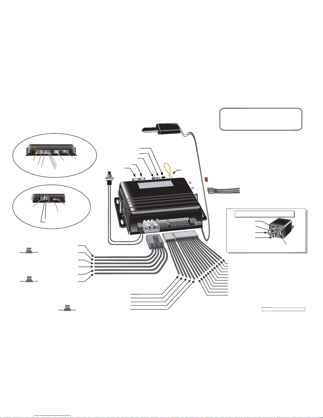
1. (-) Aux 2 output
2. (-) AUX 1 output
3. (-) Parking lights
1. GRAY/LIGHT BLUE ... (-) AUX 2 output
2. BLUE/WHITE ... (
-
) AUX 1 output
3. YELLOW/WHITE ....... ( PARKING LIGHTS
-)
12- YELLOW .......................... (+) Glow plug input
11- GREY ............................... (
-
) NEG. Door input
10- WHITE .............................. (
-
) GROUND when running
9- PURPLE ............................ (
-
) EXT. TRIGGER input
8- ORANGE ........................... (
-
) Parking Brakes input
7- WHITE/ORANGE ............... (
-
) Starter kill output
6- BLUE/WHITE ..................... (+) POS. Door input
5- WHITE/GREEN .................. (
-
) DISARM
4- WHITE/BROWN ................. (
-
) REARM
3- GREEN .............................. (
-
) UNLOCK
2- BROWN ............................. (
-
) LOCK
1- BLUE ................................. (
-
) TRUNK
Loop
LOOP
V1.00 SS - Feb. 18, 2009 -
Jumpers for second outputs
(Starter, Ignition, Accessories)
Starter 2 Jumper
Ignition 2 Jumper
Accessories 2 Jumper
INV-200 Connector
INV-200 CONNECTOR
(Door Lock pulse
inverter)
RS-232 Port
RS-232 port
Bypass/GPS port
Bypass/GPS port
Pager port
Pager port
REAR VIEW OF MODULE
PUSH-BUTTON
VALET SWITCH
(N/A)
GREEN ............ 5
th
RELAY
PURPLE ............. STARTER
ORANGE ...ACCESSORIES
(Heater Blower Motor)
YELLOW ........... IGNITION
RED ............+12V (Battery)
RED ..............12V (Battery)
30 A Fuse
30 A Fuse
1- BLACK ........................ GROUND (
-
)
2- PURPLE ........................... TACH (AC)
3- GREY ................. HOOD SWITCH (
-
)
4- ORANGE ........ BRAKE SWITCH (+)
5- YELLOW ....... PARKING LIGHTS (+)
15 A Fuse
85
87
(Solenoid Side)
86
30
STARTER WIRE
(Key Side)
IGNITION (+)
N/A
Start Kill Output (-)
87
A
STARTER WIRE
Optional Starter Kill Relay
N/A
TACH Threshold: HIGH
TACH Threshold: NORMAL
Programming
Assistance Button
(Hood Switch
Interrupt)
SIDE VIEW OF MODULE
NA
WIRING SCHEMATIC
For Automatic Transmissions
Cut the yellow loop before plugging
in the module.
:
 Loading...