

Page 1
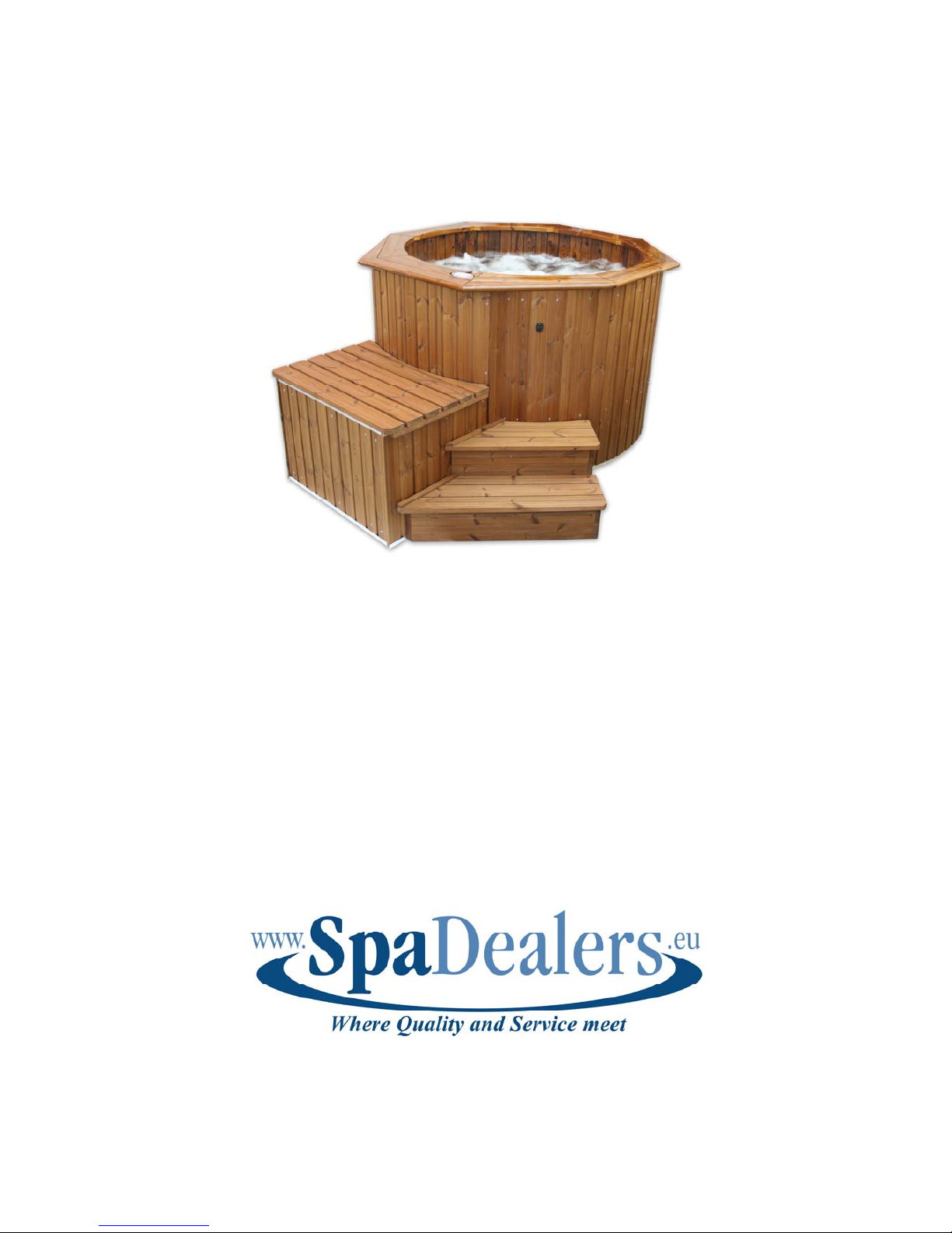
AquaKing
Additional Instructions
WARNING
Read the technical instructions before installing the bath
Do not bring sharp objects into the bath
Contact the seller if the colours appear to be changing under or on top of the coating
If a leakage appears it should be resolved from inside and without any delay
All electrical work should be perfomed by a qualified electrician
The buyer is responsible for ensuring that the instructions are followed even if
assembly is performed by a third party.
ATTENTION! If the hot tub will be integrated e.g. into a terrace it is necessary that the
access is not obstructed in any way order to be able to service it. Service hatch and
outer panel should be removable without difficulties.
Page 2
1
1
2
2
3
3
4
4
5
5
6
6
7
7
8
8
9
9
10
10
11
11
12
12
A A
B B
C C
D D
E E
F F
G G
H H
Article
Polar
Part Number
AquaKing
Material
LunaWood
Page Size
A4
Designed by
JI 01.10.08
Checked by
Aproved by
Scale
1:18
Revision
v 2.1
Sheet
22/22
1
1
1
4
6
2
6
3
9
4
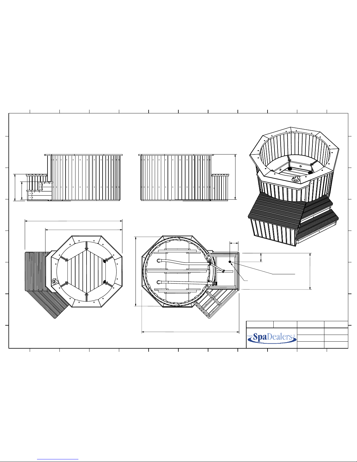
2248
1782
2289
1
6
3
5
Water drainage
and electric wiring
8
5
0
2
1
0
200
Hose Ø 33 mm
22
Page 3
1
Additional assembly instructions for Polar AquaKing (v. 092009)
Thank you for choosing a product from SpaDealers. Polar AquaKing is a unique wooden spabath
with a plastic inner lining and edging. This makes cleaning easy and protects the wood. When
assembling it is very important to follow the instructions in order to avoid leakages. Please read our
guarantee conditions and what they include.
NOTE! All wooden parts must be stored at a dry location and be dry during assembly. Never
assemble in the rain or when humidity is high.
These additional assembly instructions contain important descriptions, which refer to the picture
numbers shown in the graphic instructions. This text refers to AquaKing Jets. The assembly of
AquaKing Standard follows the same procedure, but the holes and parts needed for connecting the
jet massage are not included. If you have any queries, please contact us at +358-(0)10-239 5600
or info@spadealers.fi
Taping the joint before applying sealant
IMPORTANT! Before starting to fill the joints, masking tape should be applied according to
recommendations. See pictures 1
, 2, 3 and 4. Masking tape needs to be placed outside the pre-
marked line. Note where the masking tape starts and ends according to the letters in the pictures.
This is important, because it will be easier to remove the tape when the sealing procedure has
finished. Otherwise, there is a risk of not getting a good final finish and might cause problems later.
NOTE! Study the details in the pictures, for example the folding of the first masking tape, picture 1
/e/B. The reason for this is the fact that you need something to grip when removing the tape. Check
additional instruction “Mask properly”.
Sealing groove and nozzles for sealant
Grooves have been made in the benches and side parts in order to guarantee the best possible fit.
There are also grooves made for the sealant. Pictures 5 and 7. The assembly tools contain a nozzle
for the black sealing compound which is used to fill the cut outs and grooves.
VERY IMPORTANT! Fill the grooves with a bit more sealing compound than necessary, just that
it comes into contact with the other surface by pressing it down, see picture 5
/D. However, be
careful that you do not use too much of it, because it can get quite difficult to press the surfaces
against each other.
Assembly of seating area
The seating area is assembled so that 3 benches are assembled first, picture 7
. Then assemble the
other 3 benches and put both sets of benches facing each other, picture 8. Assemble on a clean
smooth cardboard surface or similar to avoid scratching the benches. Use the included textile hoop
in order to tighten the seating area. Place the seating area on the level shown in picture 10 /F and
tighten carefully. Carefully tap the vertical sides and the benches with a rubber mallet. The arrows
in picture 9 show the recommended places. Tighten a bit more and repeat tapping gently with the
rubber mallet. Go all the way round and try to tighten the seating area as well as possible. The
theoretical opening between the benches is 1.5 mm divided equally between all the benches. If too
much sealant has been used, it is possible that the seating area won't become tight enough. In such a
situation it can help to tap the benches and let the tightening pressure press the sealant together.
Tighten the angle bar to each seat, picture 9
/8.
Afterwards please assemble the air valves of the bubble system. It is important to apply silicone
beneath the air valves and on top of the threads. Smear the silicone down on the threads using your
finger. The rubber sealing ring should be placed on the backside and not beneath the air valves,
picture 11.
Page 4
2
Now you can start with the caulking of the seating area’s inside in alphabetical order according to
pictures 9 and 10. The sealant should be evened out until it covers the surfaces to the masking tape.
Repeat a few times. It is recommended to use your finger for this. Remember to rinse your finger
with turpentine afterwards. It´s important that the sealant is smoothed out thin towards the edge of
the masking tape, in order to make it easier to remove the tape.
Bubble system assembly
After the caulking has been completed, the bubble system’s hoses can be assembled. Note that the
placement in picture 12 shows the AquaKing Jets, where one vertical part (at the very bottom) has a
hole for connection to an extra pump for optional extra jets and lamp. The AquaKing Standard
without extras doesn’t have these extra holes. One hose for the T-connection 20x32x20 (marked
with a !) is longer than the other and it should be placed as shown in picture 12.
Adjusting the seating area to the base
When the base has been assembled the connection pipes for the pressure and suction side should be
mounted now (picture 15), the two horizontal grooves are filled with sealing compound and
smoothed out, picture 16. Now fill the sealing agent in the base’s joints, picture 17. After having
done this it is time to lift the seating area into position. The T-connection for the bubble system air
hose connection must be mounted in the same direction and place as shown in picture 17!
If the seating area is correctly assembled, it will now fit into the groove at the base. Otherwise,
adjustments might be necessary. Do these by gently tapping the vertical sides with a rubber mallet
to make them fit into the grooves. Then gently tap on top of the benches to make the assembly fall
down into the grooves and come in contact with the sealant.
Attending to the sealing joint for the seating area and base
Then turn the base upwards in order to be able to screw it to the seating area, picture 18. Use the
included screw 4.5x50 mm (3), picture 18 /3. In order to get the right distance between the base and
the bench, use the included 6 pre-cut pieces, picture 18/10. The adjustment of side modules is then
easy. After this procedure, the sealing joint between the base and the seating area must be fixed and
smoothed out, picture 19/a. Then do the same with the upper joint between the benches, picture
19
/b. Remove the masking tape now. Start at the point where the masking tape is folded and then
pull outwards, picture 20
. Let the joints dry. Check additional instruction “Mask properly”.
Preparing the side modules
While the joints are drying you can start taping the side modules joints (unless it hasn´t already
been done). It is important to do this according to the instructions. See picture 22 and tape in the
right order a-c. Check additional instruction “Mask properly”. Also check for possible small cracks
and holes due to knots in the side module where the TubCoat application does not cover. They are
unlikely, but not impossible. If you find cracks or holes, mend them by putting a bit of sealant on
top of them. Press the sealant in and smooth it out. Wipe extra sealant off with a bit of turpentine.
This gives a result that is virtually invisible.
IMPORTANT!!! Leakage test
One important part of the assembly process is the leakage test. This is first made with the seating
area. Note that the joints should be coated first. Check additional instruction “Mask properly” for
drying times in section 4. The test must be made in stages according to the graphic instructions.
Before this, the bubble system air hose with vent and connection to air pump must be mounted,
picture 30/Q. The included pipe system for pumps must also be connected and the taps must be
closed. The massage pump connection for the AquaKing Jets should be mounted with its lower part
turned towards the bench during the test, so the water doesn’t leak out. If there is a lamp
Page 5

3
(accessory), it should also be mounted according to the instructions. This can be done while the
joints dry.
Mending leakages for joints
If a leakage is detected, it should be fixed before the next test is made. Mark the leakage, empty the
water, wipe clean, mask the spot where the leakage has been detected (and at least 10 cm to each
side), put on some sealant, press it down and smooth it out with your finger. Then remove the tape.
You can now do the next test without drying time. Continue until the entire seating area has been
tested. Empty the water and then continue with the assembly of the side modules.
ATTENTION! A leakage which has not been resolved correctly can lead quite likely to other
leakages due to its material movements. A leakage should be always resolved from “inside” and
without any delay.
Side module assembly
Before starting the side module assembly, apply masking tape to the top of the benches around the
entire seating area. Follow the marked line, picture 23. Start by mounting the side module with the
hole, and place it opposite the suction and pressure side at the base. When doing the assembly, the
masked line of the side module (left and right side) must fit in so it meets exactly the line of the
joints on the seating module, picture 24
/L. When the side modules are assembled so that horizontal
and vertical joints follow each other, the result will look good. The side modules should follow the
outer line where the masking tape is, picture 24
/K, 25/M. NOTE! The side should not be tapped so
hard that they move towards the masking tape. At the base, there is also a line showing
approximately how far the three longer staves should be tapped inwards, picture 24/J.
Tightening the hot tub
After the side modules have been assembled, they must be tightened and “locked” with 2 included
stainless hoops. Follow the measurements and placing shown in picture 26. The tightening must be
made in stages. First tighten the lower part, but only until it feels a bit tight. Walk around the tub
and tap with the rubber mallet at the height where the side modules and benches are fastened to
each other. Try to get an even distance between side modules and the line where the masking tape
is. At this stage it is still possible to make the vertical groove on the side to follow the joint between
the benches. NOTE! Be careful and don’t tap the outer staves in the outer-most side module from
the side. This could cause cracks along the joint that is already plasticized. If cracks occur they must
be dealt with later according to the method that has been described earlier in the chapter
“Preparing the side modules”. Tighten the upper hoop every time the lower hoop has been fixed.
The opening between the hoops should be approx. 40 mm when they are tightened enough, picture
26/N.
Sealing benches and sides
First fill the vertical grooves between the side modules, 6 pcs, with sealant. Then apply sealant to
the joint between benches and sides, picture 27. Smooth everything out before removing masking
tape, picture 28. Let the joints dry and then add coating. Check additional instruction “Mask
properly” for drying times, section 5.
Leakage test above benches
When everything else has been assembled, including the thermostat sensor and skimmer. Use
silicone in the hole for the screws. If you have an AquaKing Jets, all the jet nozzles should also be
mounted with included hose connections. Follow separate instructions. HINT! This can be also
done while the joints are drying. A leakage test can now be made above the benches. First, fill water
over the joint where the benches and the sides are mounted, picture 29/1. Check for any leakages.
Then make the leakage test above, picture 29/2. Normally there is no reason why there should be a
Page 6
4
leakage above the benches. If not enough care has been taken when assembling the side modules,
there is a risk that a crack could occur in the thin part of the inner tongue. In such cases, the risk of
leakage above the joint between the benches and side module is high, and almost always there is
then a leakage in the side stave tongue, which makes water drip in the lower end. Find the crack and
resolve it promptly according to chapter “Preparing the side modules”.
Mounting insulation and side panels
After the leakage test has been made, the mounting of the insulation and side panels can begin. Note
the place for the first side insulation, pictures 30
/P and 31 /R. If the bubble system air connection
has not been mounted yet, do it now. See picture 30
/O for placement. Mount the side insulation so
that the upper edge is at the same height as the side modules and fasten the panel. Use a part of the
edge in order to get the panel and the insulation at the same height as the side module, picture 31.
Follow the measurements shown in picture 31 /R. HINT! Nail small nails in the side modules, 4 pcs
for each insulation sheet, which makes it easy to fasten the side insulation, picture 30
/P. Before
putting the covering shelf in place, the control system level indicator must be mounted. See separate
instructions concerning this. Assemble the rim, picture 35
, 36, 37. HINT! Use silicone around
the holes and screws. This is just to make sure that no water can get in the hole, picture 35/1/5. Do
the same where the brown protection covers for the screws will be put on, picture 37. Before
mounting the rim please put some masking tape 1 cm beneath the upper edge of the tub. When the
rim has been mounted, apply some sealing compound between thios and the side wall and smooth it
out. When finished you can take off the masking tape.
Turn the tub so that it is lying on its side (put something soft underneath) and mount the base
insulation. See page 19, picture 38 och 39. Fix the bottom insulation inside the box before the
technical parts get installed. The gap between the box’s insulated sides and tub needs to be filled
with a insulation foam, picture 42.
The hot tub is now ready for use.
Remember that water hygiene is important and follow our recommendations concerning this. We
hope you thoroughly enjoy your spa bath!
Page 7
Mask properly
In order to make the work on the joints
easier and more secure (no leaks) it is
important that the masking is done in
accordance with our directions. We
also recommend that the joints are
coated afterwards to protect agai nst
chemicals and eventual wear on the
joints. The following text illustrates
how to properly mask and do the
joints.
Masking for coating
-holes for ”guide rod” are turned
upwards
• Start with taping about 1 cm
outside the lines that are marked
up. The exact distance is not
important but try to make a straight
line. Press the tape down in one
end and keep it stretched in order
to easily get a straight line.
• Put the following lines of tape so
that every new tape is on top of
the preceeding one.
• The end of the last line of tape
however is put under the first bit of
tape (picture 3). Trim the tape so
the edge follows the edges of the
tape underneath as picture 3 and
4 illustrates. See guide
“Sanding”.
• Put the first tape bit over the last
one and then fold an edge
that you
can easily grasp later when you
will remove the tape, see picture 4
and 7. This way the tape will be
easy to remove.
Masking for the joints
-holes for ”guide rod” are turned
upwards
Repeat the steps above but instead
follow the line
that determines where
the seam ends.
The same principle is used for all parts
that will be joined and coated.
When the masking for the joints is
removed the tape for the coating will
remain, this way you can easily coat
the joints and get an aesthetically
pleasing result. The masking is
removed when the coating is done
43
21
5
6
7
4
1
3
1
2
3
4
2
Page 8

The same principle is used for all parts that will be joined and coated.
1 2
3 4
5 6
~20mm
~20mm
Page 9
9 10
11
7 8
12
~5mm
~
10mm
Page 10

Mask the base parts according to the same principle
Begin masking the side modules when the joints on "sitting well" are done.
13 14
Page 11

Trim the masking tape for the
coating about 1 cm in from the line
that marks the joints.
See guide “Sanding” before doing this
step
1. Mask with tape along the lines for the
joints on both sides.
2. Then do the lower line for the joint.
3. Trim the edges of the tape so they follow
the lines.
All the joints, except the one that will later
be applied to the "sitting well" are now
done. See page 11 in the graphical man ua l.
Page 12

5. When the side modules are assembled and the sealing mass has dried for at least 6 hours, the vertical joints and the
j
oint between the seat and side should be coated using the method illustrated earlier. Let it dry for at least 12 hours
before checking for leakage. If the application of coating is made after the bath has been in use then the coating
should be applied only after the joints, and a small area out from this, are cleaned with acetone and sanded.
Coating of joints Improper use of chlorine, or some other combination of chemicals, can damage the sealing mass
that is used on the joints. It’s therefore recommended that the joints on the benches, between the side and bottom modules
are treated with a layer of coating to protect them. The joints first have to be dry and clean. This guide describes this
process in detail during the assembly stage. If the coating is applied after the tub has been in use, then all joints and the
area a few centimeters around the joints has to be cleaned with acetone or an similar product and sanded. WATCH OUT!
When coating the tub with TubCoat it is important that the surface is t otally dry and that the proc ess itself won't be done
within a humid environment otherwise it results in a grey-whitish colour while hardening. Because of the same reas o n the
material needs to dry at least 12 hours before it gets in contact with water.
2. In order to get a good looking result the
masking is applied “double”. See “Mask
properly”. Remove the masking tape for the
j
oints. Let it dry for at least 6 hours before
1. The coating consists of two components,
"Comp. A" and "Comp. B", the mixing ratio is
4:1 (A:B)
4. Turn the seating area and apply coating onto
the joints between the seats and the two joints in
the base. Remove the tape afterwards. Wait 5
hours and then apply new masking, sanding and
plastic application according to ”second
coating”
3. Mix up 50 ml Comp. A and 12.5 ml Comp. B
and apply the coating over the joints. HINT! Turn
the base on it's edge to see better. First hold the
brush so it covers the joint and then so the coating
is also applied outside the joint itself.
Page 13

SANDING
To ensure the coating will take a firm hold, sanding shall be done inside the
first masking and out against the edge before the second masking is applied.
Page 14
1. First coating
3. Apply new masking at the outer edges,
folliwing the same line as before, when it
has dried.
4. Apply masking along the innermost
black line on the seating well.
5. The sides are assembled and a joint is
made with sealer around the seating well
and sides.
3.1 Lightly sand inside the masking
2. Masking removed
6. When the sealing mass has dried the joints are
to be coated inside the masking, which can then
be removed afterwards.
Second Coating
Page 15

Bubble system assembly
Picture shows parts,
Drive the air jet into the hole using a rubber mallet.
Note! Remove gasket before. Hold it from
underneath and support the part with your arm.
Remove the air jet.
Picture shows air jet + gasket installed.
Screw on and tighten underneath. Do not forget to
put the thicker gasket in between first!
The finished part.
Gasket
Gasket
Assemble the air jet. The thinner of the gaskets is
placed on the top side.
Gasket
Page 16

The airjet should be coated with silicon before the
T-connection is attached
Apply silicon on the airjet
Silicon applied Smear out the silicon
Attach the T-connection The finished part.
Page 17

– Gäller endast om du har AquaKing Jets –
– Only applies if you have AquaKing Jets –
1
2
3
4
5
6
Page 18

Page 19

The pictures show the installation of the temperature sensor.
Page 20

Assembly of edge
Apply masking tape as shown on picture Then apply sealing sikaflex in the joint
Spread out the mass as see in in picture 3
Remove masking tape. Repeat procedure
for remaining joints.
Picture shows one section of the edge and placement of the parts.
3
1 2
4
Page 21

Mask with tape about 1cm below the hot tubs lower edge before
the rim is attached. See steps 36-37 in the main assembly guide
on how to assemble the rim.
When the edge is in plane, mask the edges
on the edge with masking tape and sand the
area with scotch brite as shown in picture 1.
Apply the masking so there is a 1,5mm
space between the rounded edge and the
tape.
1
2
Apply a new layer of tape on top that goes
all the way to the edge.
Apply mass in the joint as shown in picture
3.
Spread out the mass with, for instance, a
spatula as shown in picture 4. Check that
the mass covers the whole joint all the way
around so it meets up with the seal that was
made on underside of the edge.
3
4
Page 22

Apply silicone under the control panel before it is attached to the edge. It is enough to push
it down into the hole and it will be securely fastened when the silicone has dried.
Apply silicone around the
hole before you insert the
p
lastic plug. After the
silicone has dried excess
material can be pulled off.
Then make a protective
seal between tub and rim
using silicone.
Remove the top layer of masking tape
quickly.
Repeat the procedure for every joiint, when
the mass has dried apply TubCoat over the
j
oints and remove the remaining masking
tape.
5 6
Page 23

Picture 2 show how the air pump for the bubble system is placed.
It should not be oriented with the air exhaust upwards.
If the AquaKing is equipped with the BactiSafe (accessory) then it is positioned according to picture 1.
The control system is fastened in the position that is shown in picture 2.
Connect the nut to pump and filter properly (picture 3)
3
When installing the insulated box insulating foam (polyurethane) will be applied between the side insulation
of the spa bath and the boxe's insulation, see picture. The insulatio n be neath the lid of the box should not be
used when the temeprature indica te s more than + 10 degrees. To protect BactiSaf e a ga i nst damage from
freezing it should be drained by loose ning the stainless nut and the sealing around the glass tube.
Lowering into terrace ATTENTION! If the hot tub will be countersunk e.g. in a terrace it is necessary
that the access is not obstructed in any way order to be able to service it. Service hatch a n d ou ter p anel should
be removable without difficulties.
1 2
 Loading...