

Page 1
15” / 19” HD LCD TV & DVD Combo
Questions?
Need some help?
This manual will help you
understand your new product.
If you still have questions,
call our help line found on
the insert with this icon:
Or visit
www.polaroid.com/support.
Page 2

©2007 by . All rights reserved.
“Polaroid” and “Polaroid and Pixel” are trademarks of Polaroid Corporation, Waltham, MA, USA.
Changes are periodically made to this document. Changes, technical inaccuracies, and
typographic errors will be corrected in subsequent editions.
For service, support and warranty information, visit www.polaroid.com.
This product contains electrical or electronic materials. The presence of these materials may,
if not disposed of properly, have potential adverse effects on the environment and human
health. Presence of this label on the product means it should not be disposed of as unsorted
waste and must be collected separately. As a consumer, you are responsible for ensuring that
this product is disposed of properly. To fi nd out how to properly dispose of this product, please
go to www.polaroid.com and click on “Company“ or call the customer service number for your
country listed in the instruction manual.
Manufactured under license from Dolby Laboratories.
“Dolby” and the double-D symbol are trademarks of Dolby Laboratories.
Confi dential unpublished works. © 1992 -1997 Dolby Laboratories, Inc. All rights reserved.
This TV incorporates High-Defi nition Multimedia Interface (HDMITM) technology.
HDMI, the HDMI logo and High-Defi nition Multimedia Interface are trademarks or registered
trademarks of HDMI Licensing LLC.
Page 3
FCC
Federal Communications
Commission Statement
This equipment has been tested and found to comply with the limits of a class B digital device,
pursuant to Part 15 of the FCC Rules. These limits are designed to provide reasonable protection
against harmful interference in a residential installation. This equipment generates, uses and can
radiate radio frequency energy and, if not installed and used in accordance with the instructions, may
cause harmful interference to radio communications. However, there is no guarantee that
interference will not occur in a particular installation. If this equipment does cause harmful
interference to radio or television reception, which can be determined by turning the equipment off
and on, the user is encouraged to try to correct the interference by one or more of the following
measures:
1. Reorient/Relocate the receiving antenna.
2. Increase the separation between the equipment and receiver.
3. Connect the equipment into an outlet on a circuit which is different from what the receiver is
connected to.
4. Consult the dealer or an experienced radio/TV technician for help.
Changes or modifications not expressly approved by the manufacturer
responsible for compliance could void the user authority to operate the
equipment.
ENGLISHENGLISH
1
Page 4
Warnings and Precautions
Warnings and Precautions
To prevent any injuries, the following safety precautions should be observed in the installation, use,
servicing and maintenance of this equipment.
Before operating this equipment, please read this manual completely, and keep it nearby for future
reference.
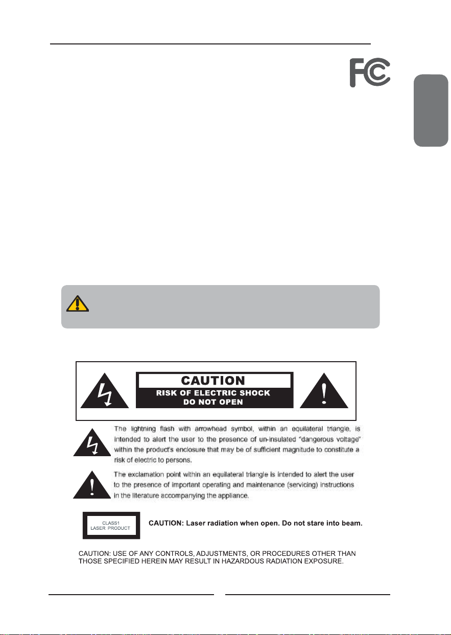
This symbol is intended to alert the user to avoid the risk of electric shock.
WARNING
CAUTION
This equipment must not be disassembled by anyone except qualifi ed service personnel.
This symbol is intended to alert the user to the presence of important operating and
maintenance instructions in the literature accompanying the appliance.
To reduce the risk of fi re or electric shock, do not expose this equipment to rain or moisture.
▪ TO REDUCE THE RISK OF ELECTRIC SHOCK,
▪ DO NOT REMOVE COVER (OR BACK).
▪ NO USER-SERVICEABLE PARTS INSIDE.
▪ REFER SERVICING TO QUALIFIED SERVICE PERSONNEL.
Use of controls, adjustments or performance of procedures other than those specifi ed herein
may result in hazardous radiation exposure.
Important Safety Instructions
This symbol indicates caution points.
This symbol indicates actions that should not be done.
This symbol indicates actions that must be performed.
▪ Do not place the equipment on any uneven or unstable carts, stands, tables, shelves etc.
The equipment may fall, causing serious injury to children or adults and serious damage to
the equipment itself.
▪ Use only a cart or stand recommended by the manufacturer. This equipment and
recommended cart or stand should be handled with care. Quick stops, excessive force, and
uneven surfaces may cause the equipment and cart/stand to overturn.
▪ Do not disable the 3-wire grounding type plug. The grounding pin on the 3-prong plug is an
important feature. Removing the grounding pin will increase the risk of damaging the
equipment.
▪ If you can not fi t the plug into the electrical outlet, contact an electrician to install a grounding
outlet.
▪ Always operate this equipment from the type of power source indicated on the rear of the
serial/model plate.
▪ Never overload wall outlets and extensions.
2
Page 5

Warnings and Precautions
▪ Use and handle the power cord with care. Do not place any heavy objects on the AC
power cord.
▪ Do not pull the AC power cord. Do not handle the AC power cord with a wet hand.
▪ Do not touch the power cord and antenna cable during lightning.
▪ Remove the plug from the wall outlet, if the equipment will not be used for a long period
of time.
▪ Do not place, use or handle this equipment near water.
▪ Never expose the equipment to liquid, rain, or moisture.
Seek for service if any of the above is spilled into the equipment.
▪ Do not expose the equipment to extreme temperature or to direct sunlight, as the
equipment may heat up and suffer damage.
▪ Do not install the equipment near any heat sources such as radiators, heat registers,
stoves, or any other apparatus that might produce heat.
▪ Do not attempt to service the equipment yourself.
▪ Opening and removing the covers may expose you to dangerous voltage or other
hazards and may void your warranty. Refer service to qualifi ed personnel.
▪ Do not place or drop any other objects on top.
▪ Do not insert anything into the ventilation holes of your equipment.
Inserting any metal or fl ammable objects may result to fi re or electric shock.
▪ Protect the power cord from being walked on or pinchrd particularly at plugs ,convenience
receptacles, and the point where they exit from the apparatus.
▪ Do not place the equipment on uneven or unstable carts, stands, tables, shelves etc. The
equipment may fall, causing serious injury to children or adults and serious damage to
the equipment itself.
Always place the equipment on the fl oor or on a surface that is sturdy, level, stable and
strong enough to support the weight of the equipment.
▪ Do not block any ventilating openings. Leave an open space around the equipment.
Never place the equipment :
on a bed, sofa, rug, or any other similar surfaces; too close to drapes/curtains/walls, in a
bookcase, built-in cabinet, or any other similar places that may cause poor ventilation.
▪ Unplug this apparatus during lightning storms or when unused for long periods of time.
▪ Refer all servicing to qualified service personnel. Servicing is required when the
apparatus has been damaged in any way, such as power-supply cord or plug is
damaged, liquid has been spilled or objects have fallen into the apparatus, the apparatus
has been exposed to rain or moisture, does not operate normally, or has been dropped.
▪ Always remove the power cord from the outlet before cleaning the equipment.
▪ Never use liquid or aerosol cleaners on the equipment.
Clean only with a soft dry cloth.
ENGLISHENGLISH
▪ Only use attachments/accessories specified by the manufacturer.
3
Page 6
Warnings and Precautions
Outdoor Antenna Safety Instructions
If an outdoor antenna is connected, follow the precautions below:
▪ An outdoor antenna should not be located in any area where it could come in contact with
overhead power lines, or any other electric light or power circuits.
▪ When installing an outdoor antenna system, extreme caution should be taken to prevent
contact with power lines. Direct contact with power lines may be fatal and should be avoided
at all costs.
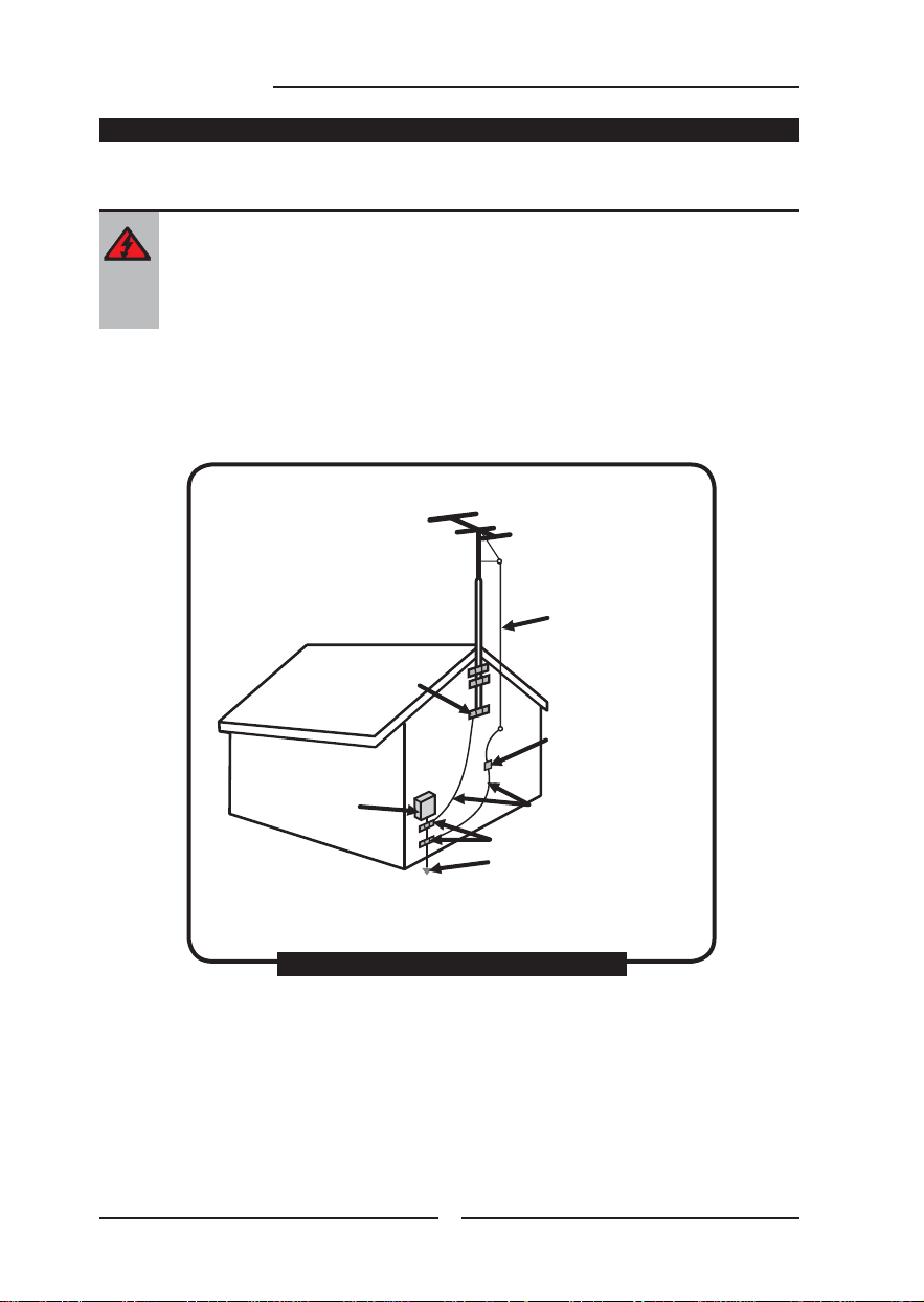
Section 810 of National Electrical Code (NEC) provides information with respect to proper grounding of the
mast and supporting structure, grounding of the lead-in wire to an antenna discharge unit, size of grounding
conductors, location of antenna discharge unit, connection to grounding electrodes, and requirements for
the grounding electrode.
Antenna lead-in wire
Ground clamps
Electric service
equipment
Ground clamps
Power service grounding
(NEC Art250 part H)
NEC : National Electrical code
EXAMPLE OF OUTDOOR ANTENNA GROUNDING
4
Antenna discharge unit
(NEC section 810-20)
Grounding conductors
(NEC section 810-20)
Page 7

TABLE OF CONTENTS
Federal Communications Commission Statement .......................... 1
Warnings and Precautions
Important Safety Instructions .......................................................................................2
Antenna Safety Instructions ......................................................................................... 4
Chapter 1 Introducing the LCD TV
Key Features ...............................................................................................................6
Package Contents .......................................................................................................7
Setting Your LCD TV .................................................................................................... 8
Your LCD TV ...............................................................................................................11
Your Remote Control .................................................................................................13
Chapter 2 Installing the LCD TV
Connecting a TV Cable or an Antenna ......................................................................17
Connecting an A/V Device with Composite Connector .............................................. 22
Connecting an A/V Device with S-Video Connector ..................................................23
Connecting an A/V Device with Component(YPbPr) Connector................................24
Connecting an AV Equipment with HDMI Connector ................................................. 25
Connecting an AV Equipment with DVI Connector .................................................... 26
Connecting a PC........................................................................................................ 27
Connecting an Audio Receiver or a Dolby Digital 5.1 Sound System........................28
Chapter 3 USING THE FEATURES
Using The Built-in DVD ....................................................................................29
Using The USB Storage and SD Card Reader ................................................... 31
Wide Screen Viewing ......................................................................................34
Using the Program Guide ................................................................................35
Operating the Menu ........................................................................................ 36
Customizing the VIDEO Settings ......................................................................38
Customizing the AUDIO Settings ......................................................................40
Customizing the TV Settings ............................................................................42
Customizing the SETUP Settings......................................................................44
Using the Parental Control Settings .................................................................. 47
ENGLISHENGLISH
Specifi cations ........................................................................................................52
Programming your Remote Control ......................................................... 53
5
Page 8

Chapter 1 Introducing the LCD TV
Chapter 1
Introducing the LCD TV
Key Features
Various Audio/Video terminals for external equipment connection
▪ 1 composite VIDEO input terminal
▪ 1 S-VIDEO input terminals
▪ 1 sets of component Video input terminals
▪ 1 VGA/VGA LINE input terminals
▪ 1 HDMI input terminal
▪ 1 set of Audio(L/R) input terminals for composite C-VIDEO/S-VIDEO
▪ 1 set of Audio(L/R) input terminals for component
▪ 1 COAXIAL output terminal
▪ 1 Headphone terminal
Built-In Slot-type DVD Player
▪ Supports DVD/SVCD/VCD/CD compatibility.
Built-in SD Card Reader
▪ Allows access to digital content stored on a SD card.
Built-In USB Connector
The built-in TV tuner to receive HD ATSC
▪ This function allows the reception of HD broadcasting without the addition of a set top
box.
High Definition Multimedia Interface (HDMI)
▪ High Defi nition Multimedia Interface (HDMI) is a small, user-friendly interconnect that
can carry up to 5 Gbps of combined video and audio in a single cable. This system
eliminates the cost, complexity and confusion of multiple cables used to connect
current A/V systems.
HDTV Component Video Inputs
▪ Offers the best video quality for DVD (HD1080p,1080i, 720p) and digital set-top-box
(HD1080p,1080i, 720p) connections.
3D Digital Noise Reduction
▪ This function can digitally reduce image noise to provide better picture quality.
Film-Mode Detection (3:2 Reverse Pull Down)
▪ This function can automatically detect content derived from fi lm and adjust the
interlacer’s frame matching to provide a more natural-looking, clearer image of the
moving picture.
6
Page 9

Package Contents
DVR
Chapter 1 Introducing the LCD TV
Make sure all of the following contents are included.
LCD TV
VIDEO Cable Remote Control/
AAA Batteries x 2
SET UP
CAB/
AUXDVD
TV
SAT
SLEEP
DVD MENU
PAGE
VOL CH
LAST
MUTE
ASPECT
LIVE TV
PIP
MENU
GUIDE
OK
EXIT
INFO
CC
DVR
2
3
1
ABC
DEF
5
4
JKL6MNO
GHI
9
7
8
WXYZ
PQRS
TUV
INPUT
0
ENTER
.
Power Cord
AUDIO Cable
ENGLISH
Component Cable
AC-DC Adapter
User’s Manual
Quick Start Guide
Warranty Card
These items are all you need to set up and operate the LCD TV in its basic confi guration.
Make sure all of the above contents are included in the package. If you are missing
any items, please contact the Polaroid customer service department.
7
Page 10
Chapter 1 Introducing the LCD TV
Setting Up Your LCD TV
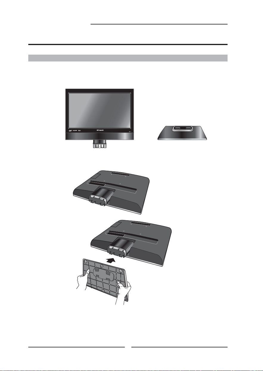
How to install the TV Stand
Follow the instructions below to install the TV stand:
Open the box, and make sure all necessary parts are in the box. The package
contains:
LCD TV
Stand
Cover an even stable surface with a soft cloth. Place the LCD TV unit face-
down on the cloth. Fit the stand onto the bottom of the LCD TV unit as shown:
Then push until stand into the LCD TV’s stand socket.
8
Page 11
Setting Up Your LCD TV
Chapter 1 Introducing the LCD TV
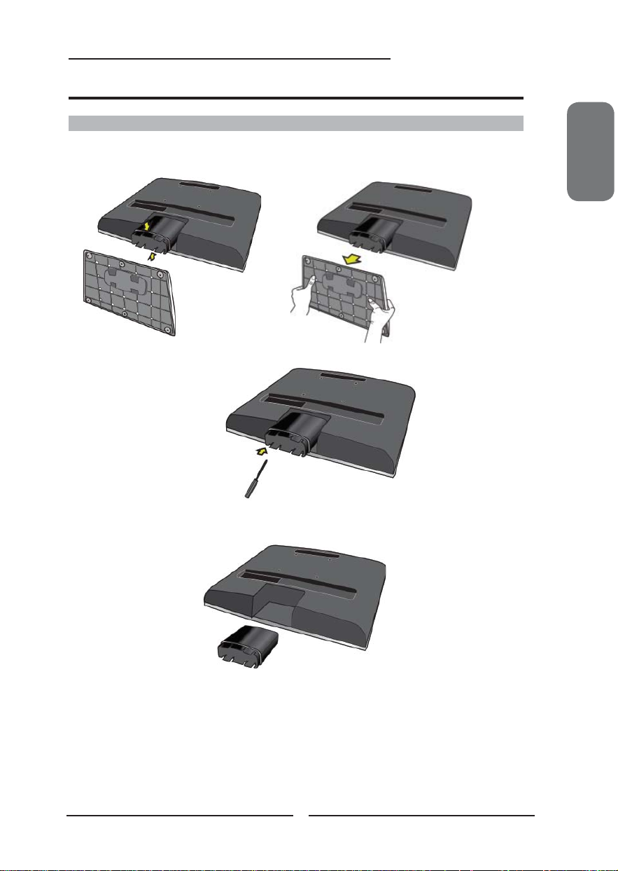
How to Remove the TV Stand
If you would like to mount your TV on a wall, please follow the instructions below:
Remove the base of the TV stand.
Use a Phillip’s head screwdriver to remove the screw inside the
neck of the TV stand.
Slide the neck of the TV stand off the rod that is connected to the back of
the TV .
ENGLISH
To attach this LCD TV to a wall, a standard 100x100 VESA mounting bracket is
required. See the VESA mounting bracket instructions (not provided) to fi nish
mounting your TV to the wall.
9
Page 12
Chapter 1 Introducing the LCD TV
How to setup the TV
Use a supplied antenna cable to connect the VHF/UHF signal to the LCD TV’s ANT.
terminal (refer to page19-20).
Connect the AC power cord at the back of the TV and connect the power cord to wall
outlet.
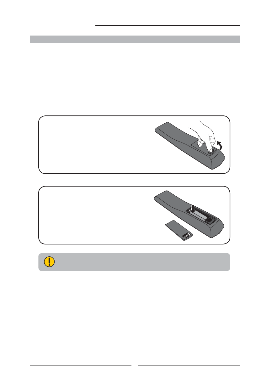
Insert the 2 batteries supplied in remote control.
Step1 Slide the back cover up to open the
battery compartment of the remote
control.
Step2 Insert two AAA size batteries.
Make sure to match the (+) and
( - ) ends of the batteries with
the (+) and ( - ) ends indicated
in the battery compartment.
Slide the cover back into place.
Do not use caustic cleaners (porcelain, stainless steel, toilet, or oven cleaner
etc.) on the remote, as it may suffer damage.
Connect other an external AV device (refer to page21-27).
10
Page 13
Your LCD TV
Chapter 1 Introducing the LCD TV
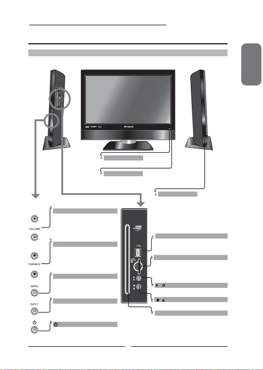
Front/Left /Right Side View and Controls
Infrared Receiver
The LED light indicates when the
LCD TV is activated.
VOLUME
+-
Adjusts the volume up and
down. Selects the main-menu
item and change values for
items when in the OSD mode.
CHANNEL▲▼
Scans up and down through
channels. Selects sub-menu
item when in the OSD mode.
MENU
Press once to display the OSD
(on screen display), press again
to turn the OSD off.
INPUT
Chooses from different input
signal sources.
Turns the LCD TV on and into
standby mode.
IR
LED
Front View
11
Left Side ViewRight Side View
HEADPHONE
Connects to the external headphone
for private listening.
USB
Allows access to digital content stored
on a USB storage : MP4/JPEG
BUILT-IN SD CARD READER
Allows access to digital content stored
on a SD card : JPEG/MPEG1/MPEG2/
MPEG4
/
PLAY/PAUSE
/
STOP/EJECT
SLOT-TYPE DVD PLAYER
Any of the following disc types can
be played on the DVD player: DVD/VCD/
CD/CD-R/CD-RW/JPEG/KODAK
PICTURE CD/WMA/DVD+R/RW/DVD-R/
RW/MPEG-4
ENGLISH
Page 14
Chapter 1 Introducing the LCD TV
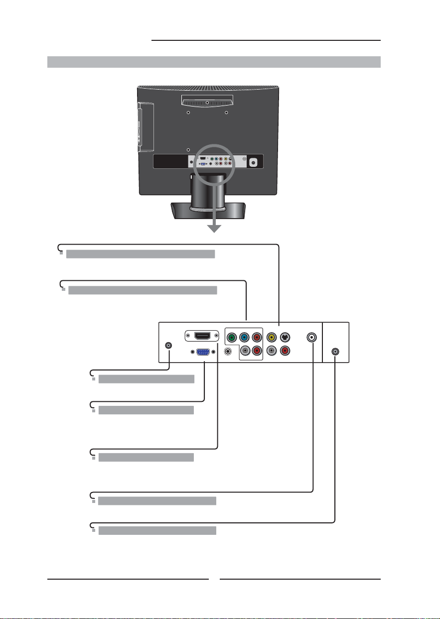
Rear View and Jacks
S-VIDEO/VIDEO/AUDIO(L/R) IN
Connects to the S-Video/Composite VIDEO and AUDIO(L/
R) output jacks on external video equipment.
YPbPr IN
Connects to the DVD player, Digital Set-Top-Box, or
other AV equipment with component(YPbPr) video
and audio output jacks.
HDMI IN
VGA IN
YPbPr
VGA LINE IN
YPbPr IN
VIDEO S-VIDEO COAXIAL
LR LR
VHF/UHF IN
DC IN
Connects to the AC-DC adapter
VGA IN/ VGA LINE IN
Connects the PC, or other AV
equipment with VGA and AUDIO
output jacks.
HDMI IN
Connects the all digital AV equipment with HDMI
connector.HDMI supports enhanced, high-defi nition
video and two-channel digital audio.
SPDIF OUT
Connects to the audio jack on the digital/standard 5.1 audio system.
VHF/UHF IN
Connects RF input from VHF/UHF antenna or cable
to receive high/standard defi nition television.
12
Page 15
DVR
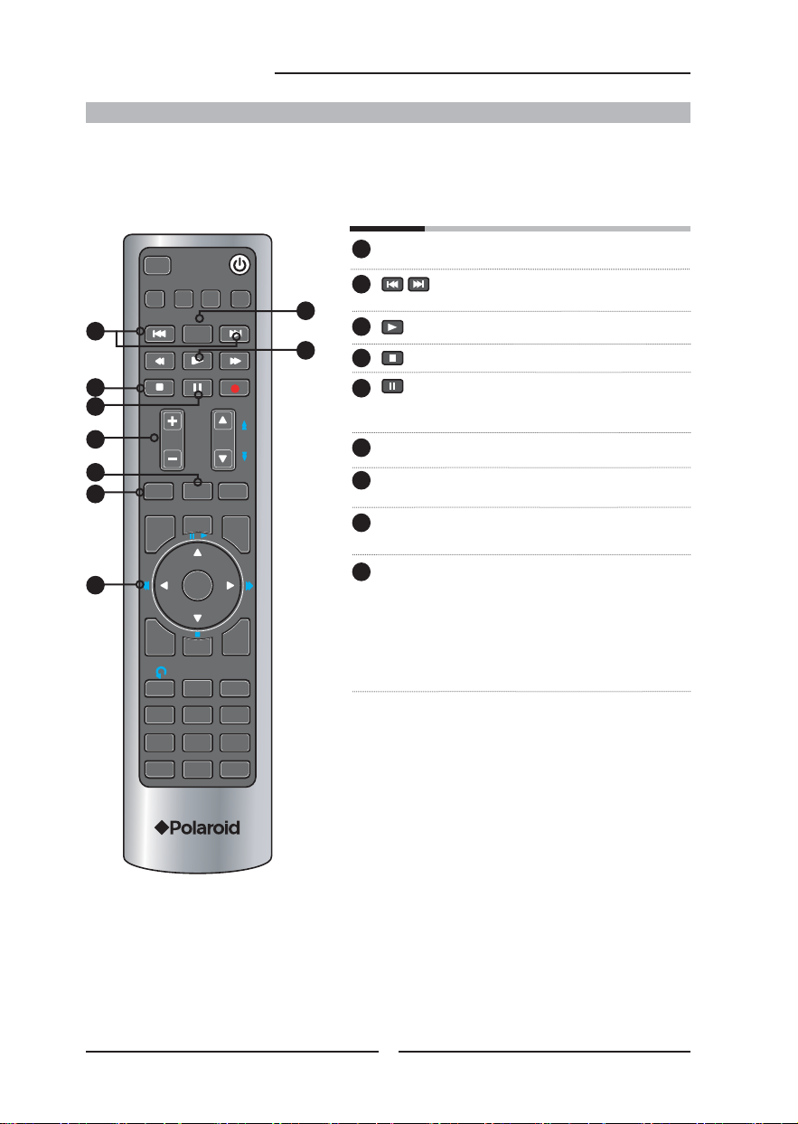
Your Remote Control
Chapter 1 Introducing the LCD TV
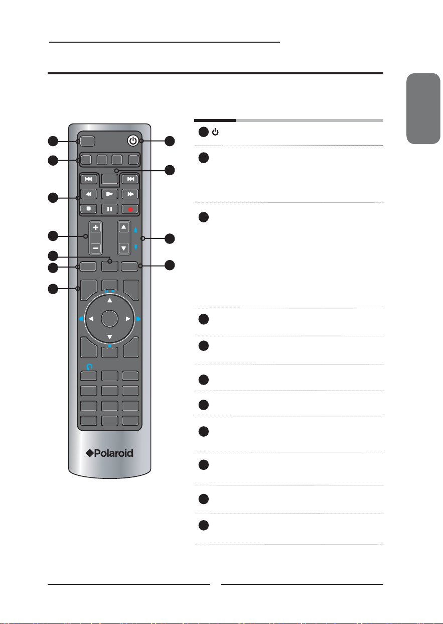
This package includes a Polaroid remote that enables control of up to four devices.
To select a device, simply select one of the following device mode controls: TV, CBL/SAT, DVD/VCR,
or AUDIO.
Turns the LCD TV on and off
2
3
SET UP
TV
CAB/
SAT
SLEEP
DVD MENU
1
AUXDVD
4
5
1
SET UP Remote control universal code setup.
2
2
For more information on setting up your
remote control, please see the
“Programming Your Remote Control”
section (refer to page 56)
TV Controls the LCD TV/Built-in DVD/USB /
3
SD card reader.
11
6
VOL CH
8
MUTE
9
ASPECT
GUIDE
LIVE TV
PIP
OK
PAGE
LAST
MENU
10
7
CAB/SAT Controls Cable Converter or Satellite
Receiver
DVD Controls DVD player or Video player
AUX Controls Audio Amplifi er
4
2
SLEEP Cycles through the LCD TV sleep time:
OFF/10/20/30/40/50/60/90/120 mins
5
INFO
1
4
GHI
7
PQRS
INPUT
.
CC
2
ABC
5
JKL6MNO
8
TUV
0
ENTER
EXIT
DEF
WXYZ
3
9
► Other device function keys
6
VOL+- Increases and decreases volume
7
CH▲▼ Change channel up and down
8
ASPECT Cycles through Wide mode settings:
NORMAL/FULL/WIDE/ZOOM
ENGLISH
9
MUTE Pressing once mutes audio. Pressing
again restores audio
10
LAST Returns to previously selected channel
11
GUIDE In TV mode, pressing GUIDE displays
the Program Guide on the screen
13
Page 16
Chapter 2 Installing the LCD TV
DVR
SET UP
CAB/
TV
SAT
SLEEP
DVD MENU
AUXDVD
12
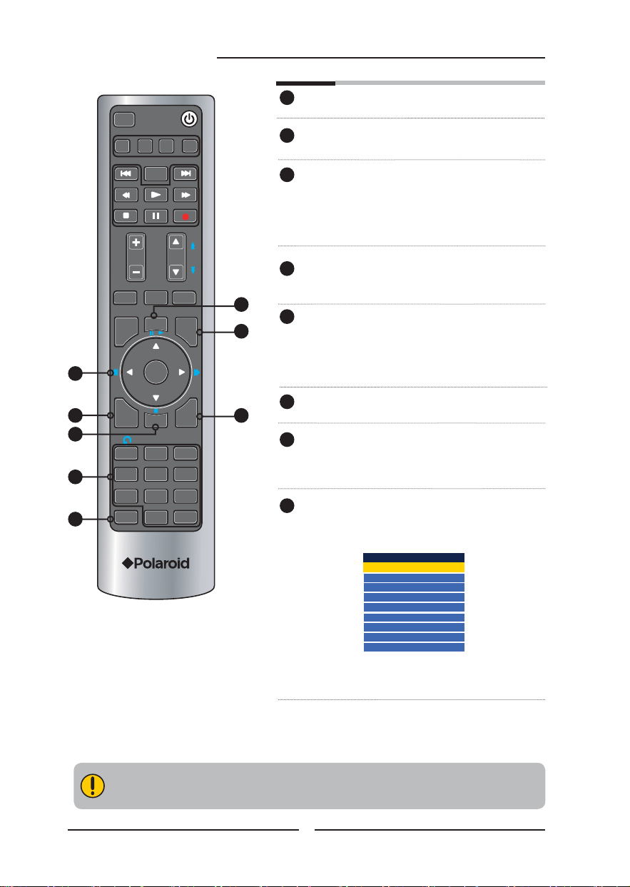
PIP Other device function key
13
MENU Displays the OSD menu on the
screen.
◄ ►▲▼,OK Cycles through OSD options and selects
14
individual menu items. OK confi rms option
OK In TV mode, pressing OK to display a
channel list
settings
14
15
16
18
19
VOL CH
MUTE
ASPECT
LIVE TV
GUIDE
INFO
1
4
GHI
7
PQRS
INPUT
.
PIP
OK
CC
2
ABC
5
JKL6MNO
8
TUV
0
ENTER
LAST
MENU
EXIT
3
DEF
9
WXYZ
PAGE
INFO Displays information on the LCD TV
15
screen such as input source, channel,
program title.
12
CC Cycles through the Closed Caption:
16
13
Analog Closed Caption:OFF/CC1/
CC2/CC3/CC4/Text1/Text2/Text3/
Test4
Digital Closed Caption:
Allow to set the digital closed caption
EXIT Exits the OSD menu
17
17
18
0-9/ENTER Pressing a number selects a channel.
Following selection, pressing ENTER
activates the channel, or channel
activates automatically in 3 seconds
INPUT Pressing INPUT to display a source
19
list, use ▲▼ to select the video
equipment connected to the video
inputs of your LCD TV:
Main
TV(CABLE/AIR)
VIDEO1 (AV)
VIDEO2 (S-VIDEO)
VIDEO3 (YPbPr)
DVD
USB
CARD READER
VIDEO4 (HDMI)
COMPUTER(VGA)
▪ In TV mode, use with 0-9 and ENTER
buttons to select a digital channels.
Effective range:
The remote can control the LCD TV from up to 5m away, if pointed directly at the receiver.
14
Page 17
DVR
Chapter 2 Installing the LCD TV
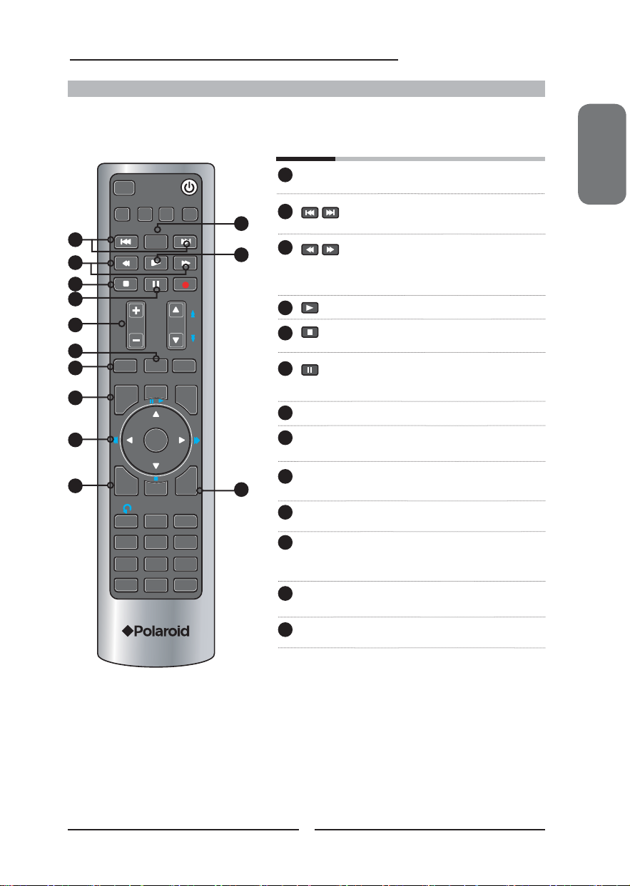
Controlling The Built-in DVD
Press the TV button once to activate the built-in DVD control keys, the following functions are preset to
operate the built-in DVD:
DVD MENU Press to display the menu of a DVD
10
11
12
SET UP
CAB/
TV
SAT
2
3
SLEEP
DVD MENU
AUXDVD
1
4
While playing, press to jump to the
2
2
Pressing this button during playback
3
5
1
6
7
VOL CH
PAGE
8
ASPECT
LIVE TV
PIP
LAST
MENU
9
MUTE
GUIDE
OK
CC
2
ABC
5
JKL6MNO
8
TUV
0
ENTER
EXIT
DEF
WXYZ
13
3
9
INFO
1
4
GHI
7
PQRS
INPUT
.
Normal playback.
4
While playing, press this button to stop
5
While playing, press this button once to
6
7
VOL+- Increases and decreases volume.
8
ASPECT Cycles through Wide mode settings:
MUTE Pressing once mutes audio. Pressing
9
GUIDE Displays the
10
11
◄ ►▲▼,OK Cycles through Built-in DVD OSD
12
INFO Displays current information on screen
disc.
previous/next chapter or track.
advances/reviews playback; speed
increases with each pressing:
2x/4x/8x/16x/32x
playing.
pause playing, press once again to
resume playing.
NORMAL/FULL/WIDE/ZOOM
again restores audio.
Built-in DVD Setup Menu
on the screen.
options and selects individual menu
items. OK confi rms option settings
during playback.
EXIT Press this button to eject the disc.
13
ENGLISH
15
Page 18
DVR
Chapter 2 Installing the LCD TV
Controlling The USB Storage and SD Card Reader
Press the TV button once to activate the built-in USB and SD Card Reader control keys, the following
functions are preset to operate the USB Storage and SD Card: For more information on setting up your
USB storagnd adn card reader, please see the “Using the USB Storage and SD Card Reader” section.
DVD MENU Press to display FILE MENU.
SET UP
CAB/
TV
SAT
2
SLEEP
DVD MENU
AUXDVD
1
3
4
5
6
VOL CH
PAGE
7
ASPECT
LIVE TV
PIP
LAST
MENU
8
MUTE
GUIDE
1
Press to go to the next or previous
2
image.
3
Normal playback.
Press to display the thumbnail album.
4
While Slide show, press this button
5
once to pause playing, press once
again to resume playing.
6
VOL+- Increases and decreases volume.
ASPECT Cycles through Wide mode settings:
7
NORMAL/FULL/WIDE/ZOOM
8
MUTE Pressing once mutes audio. Pressing
again restores audio.
◄ ►▲▼,OK In FILE MENU and thumbnail album,
9
OK
9
Press to move the highlight bar to a fi le,
then press OK to confi rm the selected
fi le.
INFO
EXIT
CC
◄ ► While image displaying, press to rotate
an image 90 degrees in a clockwise or
1
4
GHI
7
PQRS
INPUT
.
2
ABC
5
JKL6MNO
8
TUV
0
ENTER
DEF
WXYZ
3
9
counterclockwise.
16
Page 19
Chapter 2 Installing the LCD TV
Chapter 2
Installing the LCD TV
Refer to the owner’s manual of any external equipment to be connected.
When connecting any external equipment, do not connect any AC power cords to wall outlets
until all other connections are completed.
Connecting a TV Cable or an Antenna
Antenna Connection
The antenna requirements for good color TV reception are more important than those for a black &
white TV reception. For this reason, a good quality outdoor antenna is strongly recommended.
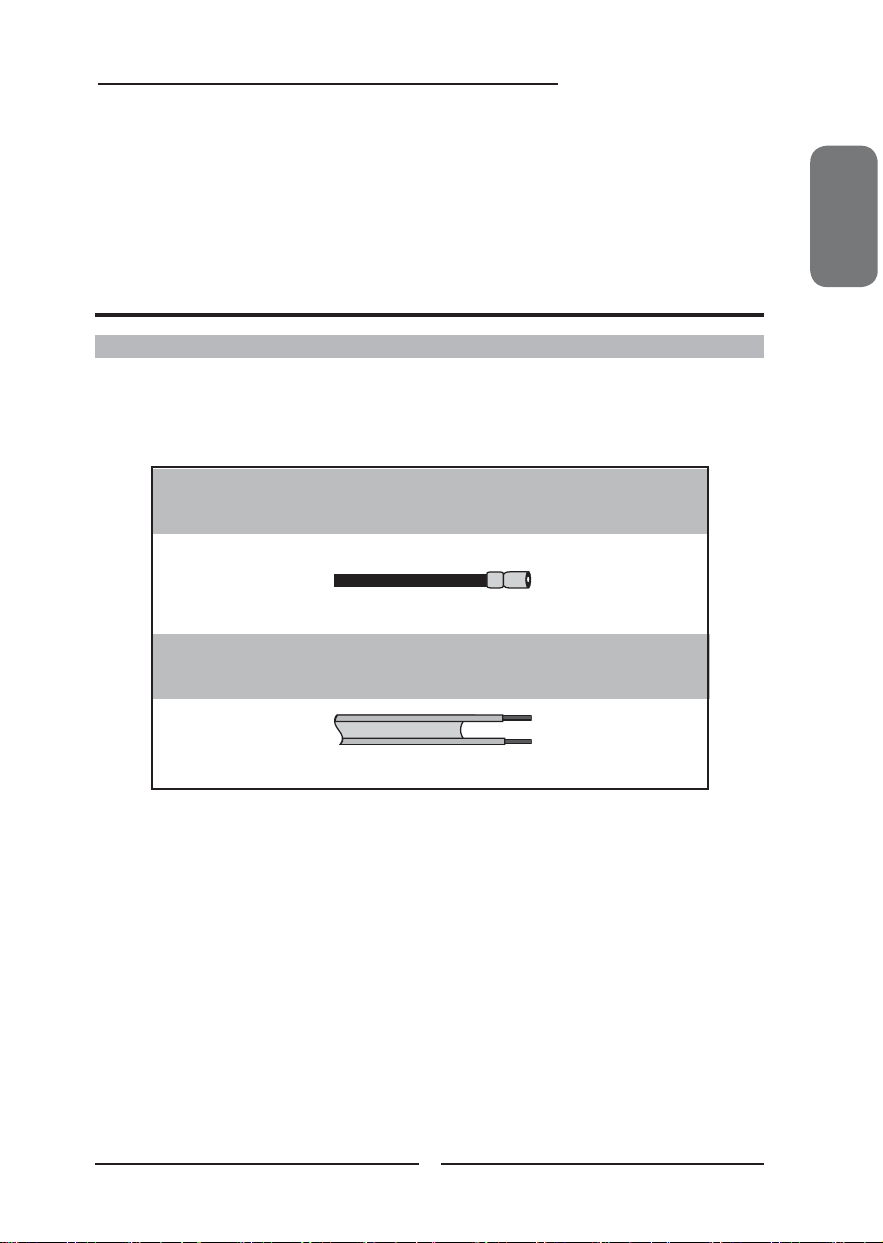
The following is a brief explanation of the type of connection that is provided with the various antenna
systems.
■ A 75-ohm system is generally a round cable (not included) with F-
type connector that can easily be at tached to a terminal without
tools.
F-type connector
75-ohm coaxial cable (round)
■ A 300-ohm system is a f lat twin-lead cable (not included) that can
be attached to a 75-ohm terminal through a 300 -75-ohm adapter
(not include d).
ENGLISH
300-ohm twin-lead cable (flat)
17
Page 20
Chapter 2 Installing the LCD TV
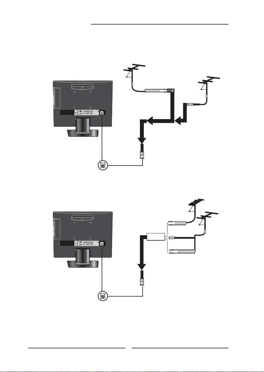
Use one of the following two diagrams when connecting an outdoor antenna.
A: Shows how to use a VHF/UHF combination outdoor antenna.
B: Shows how to use a separate VHF and/or UHF outdoor antenna.
A. Combination VHF/UHF antenna
VHF/UHF
Antenna
300-ohm twinlead cable
300/75-ohm adapter
(not included)
B. Separate VHF and/or UHF antennas
75-ohm
coaxial cable
VHF/UHF
Antenna
18
Combiner
(not included)
IN
OUT
300-ohm twinlead cable
75-ohm
coaxial cable
300-ohm twinlead cable
UHF
Antenna
VHF
Antenna
Page 21
Cable TV (CATV) Connection
Chapter 2 Installing the LCD TV
This reminder is provided to call the CATV system installer’s attention to Article 820-40 of the
National Electrical Code (NEC) that provides guidelines for proper grounding and, in particular,
specifi es that the cable ground shall be connected to the grounding system of the building
accurately, or as close to the point of cable entry as possible. Use of this TV for other than
private viewing of programs broadcasted on UHF, VHF or transmitted by cable companies for
the use of the general public may require authorization from the broadcast/cable company, and/
or program owner.
■ A 75-ohm coaxial cable connector is built into the set for easy hookup.
When connecting the 75 -ohm coaxial cable to the set, connect the 75-
ohm cable into the ANT. terminal.
■ Some cable TV companies offer premium pay channels. Since the
signals of these premium pay channels are scrambled, a cable TV
converter/descrambler is generally provided to the subscriber by the
cable TV company.
This converter/descrambler is necessary for normal viewing of scrambled channels.
(Set your TV to channel 3 or 4, typically one of these channels is used. If this is unknown,
consult your cable TV company.)
For more specifi c instructions on installing cable TV, consult your cable TV company.
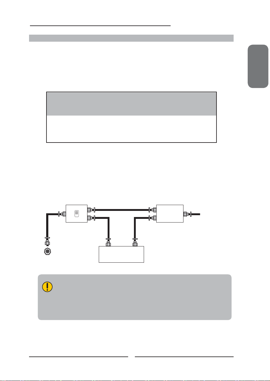
One possible method of connecting the converter/descrambler provided by your cable TV
company is shown in the diagram below.
RF switch
(not included)
2 set signal
splitter
(not included)
Cable TV Line
OUT
A
IN
B
ENGLISH
Cable TV converter/
descrambler
VHF/UHF IN
(not included)
■ The RF switch (not included) is required to provide two inputs (A and B). Setting
the RF switch to position A allows viewing of all unscrambled channels by using
the TV channel keys.
■ Setting the RF switch to position B allows viewing of all scrambled channels via
the converter/descrambler by using the converter channel keys.
19
Page 22

Chapter 2 Installing the LCD TV
Use a supplied antenna cable to connect the TV signal to the LCD TV’s TV CABLE terminal.
VHF/UHF IN
Connect the DC plug of the AC-DC adapter to the DC 12V port at the back of the TV.
Connect the AC-DC adapter and its power cord. Connect the power cord to wall outlet.
Press the button on the remote to turn on the LCD TV.
Always disconnect the LCD TV from the main voltage when the LCD TV will not
be used for a long period of time. The POWER button on the front panel is only
used for switching the LCD TV into standby, it does not disconnect the device
from the main voltage. To completely disconnect the main voltage, please
remove the power plug from the socket.
Press the INPUT button on the remote to display the Input List. Use the ▲▼ buttons to
select TV and press the OK button.
Main
TV(CABLE/AIR)
VIDEO1 (AV)
VIDEO2 (S-VIDEO)
VIDEO3 (YPbPr)
DVD
USB
CARD READER
VIDEO4 (HDMI)
COMPUTER(VGA)
20
Page 23

Chapter 2 Installing the LCD TV
Press the MENU button on the remote control to display the Main menu, and use the ◄►
buttons to select the TV.
Channel Scan
Tuner Mode Cable
Channel Skip
Time Zone Eastern Time
TV Select Exit
Press the ▼ button to select Channel Scan, and press the OK button.
The Channel Scan automatically creates a list of receivable channels. Press the
MENU button at any time to interrupt the memorization process.(the list cannot be
created if interrupted)
The Channel Scanning will create a list of receivable channels for the current
input (antenna or cable). You will be required to run Channel Scanning for each
RF input to create a list of available channels from both inputs.
Press the OK button to display the received channel list, then press ▲▼ to select a
channel. Or, use the ▪ (INPUT button) with 0-9 buttons to select digital channel( for
example 9.1)
Channel List
5-2 RF5-2
9-1 KQED-HD
9-2 KOED-SD
8 CCT
12
13
15
ENGLISH
The digital main channel might include many subchannels (for example 9-1, 9-
2..) that are showing program at the same time.
21
Page 24

Chapter 2 Installing the LCD TV
Connecting an A/V Device with Composite Connector
Rear of TV
HDMI IN
VGA IN
VGALINE IN
YPbPr IN
YPbPr
VIDEO S-VIDEO COAXIAL
R
AUDIO Cable
AV Cable
VHF/UHF IN
VIDEO OUT
L
R
GAME CONSOLE
DVD PLAYER
Use a composite cable to connect the external A/V device’s composite video/audio jacks to
the LCD TV’s VIDEO IN jacks.
Connect all AC power sources, before turning on the power switch of the LCD TV or
other connected equipment.
Press the button on the remote to turn on the LCD TV.
To view the A/V device’s with component input, press the INPUT button on the remote to
select VIDEO1.
Not all A/V devices have the ability to connect to a TV. Please check your A/V devices
user guide for compatibility.
22
Page 25

Connecting an A/V Device with S-Video Connector
Chapter 2 Installing the LCD TV
ENGLISH
Rear of TV
HDMI IN
VGA IN
VGALINE IN
YPbPr IN
YPbPr
VIDEO S-VIDEO COAXIAL
R
AUDIO Cable
S-VIDEO Cable
VHF/UHF IN
S-VIDEO OUT
L
R
GAME CONSOLE
DVD PLAYER
Use an audio cable to connect the external A/V device’s audio output jacks to the LCD
TV’s audio inputs. Use a S-Video cable to connect the external A/V device’s S-Video
output jack to the LCD TV’s S-Video IN input jack.
Connect all AC power sources, before turning on the power switch of the LCD TV or
other connected equipment.
Press the button on the remote to turn on the LCD TV.
To view the A/V device’s with component input, press the INPUT button on the remote to
select VIDEO2.
23
Page 26

Chapter 2 Installing the LCD TV
Connecting an A/V Device with Component(YPbPr) Connector
Rear of TV
HDMI IN
VGA IN
YPbPr IN
VIDEO S-VIDEO COAXIAL
YPbPr
LR LR
VGALINE IN
Pr
Pb
Cr
Cb
AUDIO Cable
COMPONENT Cable
Pr/Cr
Pb/Pb
VHF/UHF IN
COMPONENT
OUT
R
L
Pb
Pr
Y
GAME CONSOLE
DVD PLAYER
Not all A/V device have the ability to connect to a TV. Please check your A/V
device user guide for compatibility.
Use a component cable to connect the external A/V device’s component output jacks to the
LCD TV’s YPbPr IN input jacks.
Use an audio cable to connect the external A/V device’s component audio jacks to the LCD
TV’s audio input jacks.
Connect all AC power sources, before turning on the power switch of the LCD TV or
other connected equipment.
Press the button on the remote to turn on the LCD TV.
To view the A/V device’s with component input, press the INPUT button on the remote to
select VIDEO3.
The component video jacks on your A/V device are sometimes labeled YPbPr,
or YCbCr. For an explanation of component video, see your A/V device’s user
guide.
24
Page 27

Connecting an AV Equipment with HDMI Connector
Chapter 2 Installing the LCD TV
Rear of TV
HDMI IN
VGA IN
YPbPr
VGALINE IN
YPbPr IN
VIDEO S-VIDEO COAXIAL
LR LR
HDMI Cable
ENGLISH
VHF/UHF IN
AV EQUIPMENT
Use a HDMI cable to connect the AV equipment’s HDMI output jack to the LCD TV’s HDMI IN
jacks.
Connect all AC power sources, before turning on the power switch of the LCD TV or
other connected equipment.
Press the button on the remote to turn on the LCD TV.
Press the Input button on the remote to select VIDEO4.
The HDMI connector provides both video and audio signals, it’s not
necessary to connect the audio cable.
25
Page 28

Chapter 2 Installing the LCD TV
Connecting an AV Equipment with DVI Connector
Rear of TV
HDMI IN
VGA IN
HDMI-to-DVI Cable
YPbPr
VGALINE IN
YPbPr IN
VIDEO S-VIDEO COAXIAL
LR LR
AUDIO Cable
VHF/UHF IN
AUDIO
LR
DVI IN
AV EQUIPMENT
Use a HDMI-to-DVI cable to connect the AV equipment’s DVI output jack to the LCD TV’s
HDMI IN jacks.
Use an audio cable to connect the AV equipment’s audio output jacks to LCD TV’s HDMI
AUDIO jacks.
Connect all AC power sources, before turning on the power switch of the LCD TV or
other connected equipment.
Press the button on the remote to turn on the LCD TV.
Press the Input button on the remote to select VIDEO4.
If the LCD TV is connected to AV equipment’s DVI connector, you will need
an HDMI-to-DVI cable or an HDMI adapter(not supplied) and an audio cable.
26
Page 29

Connecting a PC
Chapter 2 Installing the LCD TV
Rear of TV
HDMI IN
VGA IN
YPbPr
VGALINE IN
YPbPr IN
VIDEO S-VIDEO COAXIAL
LR LR
AUDIO Cable
VGA Cable
VHF/UHF IN
PC
Use a VGA cable to connect the PC’s VGA output jack to the LCD TV’s VGA input jack.
Use an audio cable to connect the PC’s audio output jacks to LCD TV’s.
ENGLISH
Connect all AC power sources, before turning on the power switch of the LCD TV or
other connected equipment.
Press the button on the remote to turn on the LCD TV.
Press the INPUT button on the remote to select COMPUTER.
27
Page 30

Chapter 2 Installing the LCD TV
Connecting an Audio Receiver or a Dolby Digital 5.1 Sound System
For better sound quality, you may want to play the LCD monitor audio through your stereo system.
HDMI IN
VGA IN
YPbPr
VGALINE IN
YPbPr IN
VIDEO S-VIDEO COAXIAL
LR LR
Audio Receiver
VHF/UHF IN
AUDIO Cable
Use an audio cable to connect the audio receiver’s audio LINE IN jacks to LCD TV’s
SPDIF OUT jacks.
Connect all AC power sources, before turning on the power switch of the LCD TV or
other connected equipment.
Press the button on the remote to turn on the LCD TV.
28
Page 31

Chapter 3
USING THE FEATURES
Using The Built-in DVD
Turn your LCD TV on.
Insert a disc (DVD, VCD, SVCD, or audio
CD).
Chapter 3 Using the LCD TV
ENGLISH
TO INSERT A DISC
Any of the following disc types can be
played on the DVD player: DVD-Video/DVD
R/RW/SVCD/VCD/CD/CD-R/CD-RW.
Insert
The DVD player will make a sound while
the unit is turned on and the disc is
loading. This sound is normal for the fi rst
15-30 seconds while the disc is loading.
TO REMOVE A DISC
When removing the disc, do not
attempt to pull it from its slot. Please
push the EJECT button as
illustrated below.
If the disc does not eject from the DVD
player when the TV is turned on. Turn the
TV off and then back on and press the
EJECT button again. If the disc still does
not eject, call the customer service
number.
Press the Input button on the remote, use ▲▼ to select DVD and press
the OK button.
Input Source
TV(CABLE/AIR)
VIDEO1 (AV)
VIDEO2 (S-VIDEO)
VIDEO3 (YPbPr)
DVD
USB
CARD READER
VIDEO4 (HDMI)
COMPUTER(VGA)
Push
29
Page 32

Chapter 3 Using the LCD TV
00:00
00:00
001/015
01 P107001
02 P107002
03 P107003
04 P107004
05 WOFSON
06 HDCP
07 EDIT
Press GUIDE button on the remote control to display the Built-in DVD Setup Menu:
USING THE BUILT-IN DVD SETUP MENU
1. Use the ▲▼◄► on the remote control to to move the light bar to the option you
2. During playback, the following operations are available:
EJECT Stops playback.
PLAY Starts playback.
Get slow motion effect during playback
F.FWD/NEXT Jumps to the previous/next chapter or track.
AUDIO Press to select the Audio effect and Language.
SUBTITLE Changes DVD subtitle language.
CAMERA ANGLE Press to select the desired camera angle disc.
want, press the OK button.
REW./PREV. Gets different playback forward/backward speeds.
PAUSE While playing, pause playback temporarily
The Built-in DVD player can playback JPEG format pictures and audio fi les on a
personally recorded CD-R/RW disc. After loading all fi les, the File Menu will show the
contents of the disc:
001/015
01 P107001
02 P107002
03 P107003
04 P107004
05 WOFSON
06 HDCP
07 EDIT
00:00
Press ▲▼ to select an image and press the button to play the fi le.
Press ▲▼ to select the folder and then press ► to enter the folder. Press the ENTER
button to active and press ▲▼ to select a fi le. Press ◄ to back the File Menu.
While an image is displayed, press the DVD MENU button to display the File Menu.
00:00
30
Page 33

Chapter 3 Using the LCD TV
Usinging The USB Storage and SD Card Reader
Turn your LCD TV on.
Insert a USB device/SD card that contains JPG/JPEG/MPG/WMA/DAT fi les.
ENGLISH
TO INSERT A USB STORAGE
Allows the insertion of a USB storage.
You can view digital images or music in
TO INSERT A SD CARD Reader
Allows the insertion of a SD card. You
can view digital images or music.
a USB storage on your TV.
Insert
Be sure to insert the USB storage or SD card in the correct direction. If the
USB storage or SD card is forced in the wrong way, it may cause damaged.
Insert
Press the Input button on the remote, use ▲▼ to select a input source and
press the OK button.
TO INSERT A USB STORAGE
Input Source
TV(CABLE/AIR)
VIDEO1 (AV)
VIDEO2 (S-VIDEO)
VIDEO3 (YPbPr)
DVD
USB
CARD READER
VIDEO4 (HDMI)
COMPUTER(VGA)
31
TO INSERT A SD CARD Reader
Input Source
TV(CABLE/AIR)
VIDEO1 (AV)
VIDEO2 (S-VIDEO)
VIDEO3 (YPbPr)
DVD
USB
CARD READER
VIDEO4 (HDMI)
COMPUTER(VGA)
Page 34

Chapter 3 Using the LCD TV
00:00
00:00
001/015
01 P107001
02 P107002
03 P107003
04 P107004
05 WOFSON
06 HDCP
07 EDIT
After loading all fi les, the File Menu will show the contents of the USB device:
Press ▲▼ to select an image and press the button to play the fi le.
Press ▲▼ to select the folder and then press ► to enter the folder. Press the ENTER
While an image is displayed, press the DVD MENU button to display the File Menu.
001/015
01 P107001
02 P107002
03 P107003
04 P107004
05 WOFSON
06 HDCP
07 EDIT
00:00
button to active and press ▲▼ to select a fi le. Press ◄ to back the File Menu.
00:00
Do not swith the Input Source between USB and CARD READER while the
data is being reading. It may cause data loading failure.
RUNNGING A SLIDE SHOW
1. Press ▲▼ on the remote control to move the light bar to the fi le you want to play,
2. While an image is displayed full size, you can pause the slide show by pressing
.
3. Press on the remote control to go to the next or previous image.
USING THE THUMBNAIL ALBUM
1. Press button on the remote control to display the thumbnail album.
and press the OK button to play the fi le.
Slide Show ◄Prev Next►
32
Page 35

Chapter 3 Using the LCD TV
2. Press ▲▼◄ on the remote control to move the light bar to the image you
want to play, and press the OK button to play the fi le.
Slide Show ◄Prev Next►
3. Slide Show: Press ▲▼◄ to highlisht Slide Show and press the OK
button, to display all the images recorded on the SD card/USB storage.
Prev/Next: Press ▲▼◄ to highlisht Prev/Next and press the OK button,
to go to the previous or next page of the thumbnail album.
ROTATING PICTURES
1. Press ◄► on the remote control to to rotate the picture clockwise or
counterclockwise in 90-degree increments.
ENGLISH
2. Press on the remote control to go to the next or previous image.
.
33
Page 36

Chapter 3 Using the LCD TV
Wide Screen Viewing
Wide Screen function allows viewing of 4:3/16:9 images in wide screen mode, cycling through
the following wide screen settings. Press the ASPECT button repeatedly to select the screen
format you want.
NORMAL
Displays at 4:3 aspect ratio
NORMAL is not available when you are watching 720p, 1080i,
or 1080p source.
FULL
Stretches the image vertically and
horizontally to keeps the image size
consistent in the center of the screen and
stretches the sides
WIDE
Stretches the image vertically and
horizontally to fi ll the screen at 1:1.85
aspect ratio
34
Page 37

Using the Program Guide
Chapter 3 Using the LCD TV
The Program Guide feature brings all sorts of information to your screen, such as program title,
program duration, time remaining, rating information, closed caption, availability, etc.
With the LCD TV connected to a television programming source, press the INPUT button
on the remote control and use the ▲▼ buttons to select TV and press the OK button.
Press the GUIDE button on the remote control, the Program Guide will appear on the
screen:
3-1 7-2 KQED-SD 7-2
Today 7:00 PM EYEWITHNESS NEWS 4PM cc
Today 7:30 PM ABC WORLD NEWS cc
Today 9:30 PM ABC’S MONDAY NIGHT FOOTBALL cc
Tomorrow 12:30 AM SPORTSZONE cc
Monday 15 January 2007 2:36:26 PM
Press the ◄► button to select the channel.
Press the ▲▼ button to select the program from a list, the Program Guide provides
introduction about the current program being shown on each channel.
The Program information in the guide is provided by the broadcasters. It may sometimes
include only the channel number, without a program title or description.
3-1 7-2 KQED-SD 7-2
Today 7:00 PM EYEWITHNESS NEWS 4PM cc
Today 7:30 PM ABC WORLD NEWS cc
Today 9:30 PM ABC’S MONDAY NIGHT FOOTBALL cc
Tomorrow 12:30 AM SPORTSZONE cc
5:00 PM - 5:30 PM Mon, 20 Jan.
EYEWITHNESS NEWS
Monday 15 January 2007 2:36:26 PM
TV-PG
ENGLISH
Press the GUIDE button again on the remote control to exit the Program Guide
35
Page 38

Chapter 3 Using the LCD TV
Operating the Menu
Press the button to turn the LCD TV on.
Press the MENU button on the remote control, the on-screen menu will appear on the
screen. Use the ◄► buttons to select your main menu option.
VIDEO MENU:
Allows you to make adjustments to your picture settings.
▪ If the signal source is TV, the VIDEO MENU
appears as:
▪ If the signal source isVIDEO/S-VIDEO/YPbPr/
HDMI, the VIDEO MENU appears as:
Picture Mode User
Contrast 50
Brightness 54
Saturation 54
Hue 0
Sharpness 5
Color Temperature
Noise Reduction Medium
Video Select Exit
▪ If the signal source is VGA, the VIDEO MENU
appears as:
Picture Mode User
Contrast 50
Brightness 54
Color Temperature
Noise Reduction Medium
VGA
Video Select Exit
AUDIO MENU:
Allows you to customize the audio options and effects.
▪ If the signal source is VIDEO/S-VIDEO/YPbPr/
HDMI/VGA, the AUDIO MENU appears as:
Bass 50
Treble 50
Balance 0
Sound Effect Surround
Speaker On
Picture Mode User
Contrast 50
Brightness 54
Saturation 54
Hue 0
Sharpness 5
Color Temperature
Noise Reduction Medium
Video Select Exit
▪ If the signal source is TV, the AUDIO MENU
appears as:
Bass 50
Treble 50
Balance 0
Sound Effect Surround
MTS Stereo
SPDIF Type Dolby Digital
Audio Language English
Speaker On
Audio Select Exit
Audio Select Exit
36
Page 39

Chapter 3 Using the LCD TV
TV MENU:
Allows you to edit and label channels.
Channel Scan
Tuner Mode Cable
Channel Skip
Time Zone Eastern Time
TV Select Exit
SETUP MENU:
Allows you to set up a variety of features: Language, Closed Caption, factory reset, Parental Control, sleep
timer.
▪ If the signal source is TV, the SETUP MENU
appears as:
▪ If the signal source is HDMI/VGA, the SETUP
MENU appears as:
ENGLISH
OSD Language English
Time Setup
Closed Caption
Parental
Gamma Middle
Reset Default
Setup Select Exit
▪ If the signal source is VIDOE/S-VIDEO/YPbPr,
the SETUP MENU appears as:
OSD Language English
Time Setup
Closed Caption
Parental
Gamma Middle
Reset Default
Setup Select Exit
OSD Language English
Time Setup
Parental
Gamma Middle
Reset Default
Setup Select Exit
Use the ▲▼ buttons to highlight the option of the sub-menu, and press the OK
button. While in adjustment mode, and use the ◄► buttons to change the value of
the item.
Press the EXIT button to exit the menu.
37
Page 40

Chapter 3 Using the LCD TV
Customizing the VIDEO Settings
Press the button to turn the LCD TV on.
Press the MENU button on the remote control to display the Main menu, and use the
◄► buttons to select the VIDEO.
Use the ▲▼ buttons to highlight an individual VIDEO option, use the ◄► buttons to
change the setting, and press the MENU to exit the menu
▪ If the signal source is TV, the VIDEO MENU
appears as:
▪ If the signal source isVIDEO/S-VIDEO/YPbPr/
HDMI, the VIDEO MENU appears as:
Picture Mode User
Contrast 50
Brightness 54
Saturation 54
Hue 0
Sharpness 5
Color Temperature
Noise Reduction Medium
Video Select Exit
▪ If the signal source is VGA, the VIDEO MENU appears as:
Picture Mode User
Contrast 50
Brightness 54
Color Temperature
Noise Reduction Medium
VGA
Video Select Exit
Picture Mode User
Contrast 50
Brightness 54
Saturation 54
Hue 0
Sharpness 5
Color Temperature
Noise Reduction Medium
Video Select Exit
The VIDEO menu includes the following options:
Picture Mode Cycles among display types: Vivid/Hi-Bright/Cinema/Sport/User
Contrast Controls the difference between the brightest and darkest regions of
the picture
Brightness Controls the overall brightness of the picture
Saturation Controls the color intensity
Hue Controls the difference between the green and red regions of the
picture
38
Page 41

Chapter 3 Using the LCD TV
Sharpness Increase this setting to see crisp edges in the picture; decrease it for
soft edges
Color temperature Adjusts color components independently to achieve a warm or cool
effect: Cool/Middle/Warm/User
▪ Warm: Increases red tint
▪ Nature : Increases natural tint
▪ Cool : Increases blue tint
▪ User : Allows the user to adjust red, green and blue color
component levels independently.
Color Temperature User
R Gain 120
G Gain 120
B Gain 120
Color Temperature Select Exit
Noise Reduction Select to reduce the noise level of connected equipment: Off/Low/
Medium/Strong.
VGA Press the OK button to enter the VGA Setting:
Auto Adjust
H.Position 72
V. Position 31
Clock 127
Phase 31
ENGLISH
VGA Select Exit
▪ Auto Adjust Press the OK button to automatically adjust
the display settings to optimize performance
based on the VGA mode
▪ H. Position Adjusts the position of the picture left and right
in the window
▪ V. Position Adjusts the position of the picture up and down
in the window
▪ Clock Controls the width of the picture based on the
VGA mode
▪ Phase Controls the signal phase, which can improve
focus clarity and image stability based on the
VGA mode
39
Page 42

Chapter 3 Using the LCD TV
Customizing the AUDIO Settings
Press the button to turn the LCD TV on.
Press the MENU button on the remote control to display the Main menu, and use the
◄► buttons to select the AUDIO.
Use the ▲▼buttons to highlight an individual AUDIO option, use the ◄► buttons to
change the setting, and press the MENU to exit the menu
▪ If the signal source is VIDEO/S-VIDEO/YPbPr/
HDMI/VGA, the AUDIO MENU appears as:
▪ If the signal source is TV, the AUDIO MENU
appears as:
Bass 50
Treble 50
Balance 0
Sound Effect Surround
Speaker On
Audio Select Exit
Bass 50
Treble 50
Balance 0
Sound Effect Surround
MTS Stereo
SPDIF Type Dolby Digital
Audio Language English
Speaker On
Audio Select Exit
The AUDIO menu includes the following options:
Bass Controls the relative intensity of lower-pitched sounds
Treble Controls the relative intensity of higher pitched sounds
Balance Adjusts the relative volume of the speakers in a multiple speaker
Sound Effect Allows selection of an audio-enhancement technique from among the
MTS Allows you to listen to high-fi delity stereo sound while watching TV
▪ Stereo:
Use separate audio tracks for left and right speakers, if available
▪ SAP:
You can enjoy a second audio program from the speakers while
▪ Mono:
Allows mono output (useful when stereo is noisy or inconsistent)
system
following options: Surround/Live/Dance/Techno/Classic/Soft/Rock/
POP/Off
watching a scene in the original program
40
Page 43

Chapter 3 Using the LCD TV
SPDIF Type Allows to selection of the digital sound format: PCM/OFF/Dolby
Digital
▪ PCM:
The external audio system is connected to the AUDIO OUT (L/R)
of the LCD TV
▪ Dolby Digital:
The external audio system is connected to the AUDIO OUT
DIGITAL (OPTICAL or COAXIAL) ot the LCD TV
▪ OFF:
Select OFF to turn off the external audio system
Audio Language Allows to select the audio language:English/Spanish/French.
Speaker Allows to select to turn on or off the TV speakers.
ENGLISH
41
Page 44

Chapter 3 Using the LCD TV
Customizing the TV Settings
Press the button to turn the LCD TV on.
Press the MENU button on the remote control to display the Main menu, and use the
◄► buttons to select the TV.
Use the ▲▼buttons to highlight an individual TV option, use the ◄► buttons
changes the setting, and press the MENU exits the menu.
Channel Scan
Tuner Mode Cable
Channel Skip
Time Zone Eastern Time
TV Select Exit
The TV menu includes the following options:
Channel Scan Press the OK button,
creates a list of receivable channels.
Tuner Mode Allows selection between CATV cable and antenna signal sources:
▪ AIR
Choose this setting if you are receiving TV channels with an antenna
▪ Cable
Choose this setting if you are receiving TV channels with a CATV
(over the air)
(cable TV)
Channel Skip Allows addition/removal of channels on the channel list.
Press the OK button to display the Channel Skip menu:
the Channel Scanning automatically
2 ABC Analog
3 DISC Analog
4 Analog
5 Analog
6 Analog
7 Analog
8 Analog
9 Analog
10 Analog
Channel Skip Select Exit
42
Page 45

Chapter 3 Using the LCD TV
Press the ▼ button to select the desired channel, andpress the
OK button repeatedly to select show () or hide()
Time Zone Allows selection of regional TV systems of USA: Eastern Time/
Indiana/Central time/Mountain Time/Arizona/Pacifi c Time/Alaska/
Hawaii
ENGLISH
43
Page 46

Chapter 3 Using the LCD TV
Customizing the SETUP Settings
Press the button to turn the LCD TV on.
Press the MENU button on the remote control to display the Main menu, and use the
◄► buttons to select the SETUP.
Use the ▲▼buttons to highlight an individual SETUP option, use the ◄► buttons to
change the setting, and press the MENU to exit the menu.
▪ If the signal source is TV, the SETUP MENU
appears as:
▪ If the signal source is HDMI/VGA, the SETUP
MENU appears as:
OSD Language English
Time Setup
Closed Caption
Parental
Gamma Middle
Reset Default
Setup Select Exit
▪ If the signal source is VIDOE/S-VIDEO/YPbPr,
the SETUP MENU appears as:
OSD Language English
Time Setup
Closed Caption
Parental
Gamma Middle
Reset Default
Setup Select Exit
OSD Language English
Time Setup
Parental
Gamma Middle
Reset Default
Setup Select Exit
The SETUP menu includes the following options:
OSD Language Selects to display all on-screen menus in your language of choice:
English/French/Spanish
44
Page 47

Chapter 3 Using the LCD TV
Closed Caption Allows to select from analog or digital closed caption modes and
press the OK button. The Closed Captain list appears:
Analog Cloaed Caption Off
Digital Cloaed Caption Off
Digital Caption Style
Closed Caption Select Exit
Analog Closed Caption:
Press the ◄► buttons to select the basic analog closed caption
options: OFF/CC1/CC2/CC3/CC4
▪ CC1 /CC2 /CC3 /CC4:
Display a printed version of the dialog and sound effects of the
program being viewed
▪ T1/T2:
Display station information presented using either half or the
whole screen
▪ T3/T4:
Extended Data Services. For example: Network name, program
name, program length, etc.
Digital Closed Caption:
Press the◄►buttons to select the digital closed caption option.
Note: The setting here will be applied to each DTV channel
ENGLISH
Caption Style:
Press OK button to customize the settings for digital closed
caption option:
Caption Style Custom
Font Size Large
Font Color White
Font Opacity Solid
Background Color Black
Background Opacity Solid
Window Color Black
Window Opacity Translucent
Closed Caption Style Select Exit
Parental The Parental Control can be set up to the TV to block Channel,
Video Source and to change password.
45
Page 48

Chapter 3 Using the LCD TV
Use the ▼ button to select the Parental, and press the OK
to display the Parental menu
Use the Program Block function, must enter a four-digit
password. The factory password is 0000
The Parental list appears:
Program Block Allows to setup the TV and MPAA Rating
Lock options (refer to “Using the Program
Block Setting”).
U.S.TV Ratings
U.S. Movie Ratings
Canadian English Ratings
Canadian French Ratings
Block MPAA Unrated NO
Block TV Unrated NO
Parental Block Select Exit
Channel Block Allows to block digital channels.
2 ABC Analog
3 DISC Analog
4 Analog
5 Analog
6 Analog
7 Analog
8 Analog
9 Analog
10 Analog
Channel Block Set OK Select Exit
Input Block Selects to block a Input source signal
1 TV(CABLE/AIR)
2 VIDEO1 (AV)
3 VIDEO2 (S-VIDEO)
4 VIDEO3 (YPbPr)
5 DVD
6 USB
7 CARD READER
8 VIDEO4 (HDMI)
9 COMPUTER(VGA)
Input Block Set OK Select Exit
Change Password Selects to change your password
Gamma Allows adjustment of the display’s gamma correction, which fi netunes
both brightness and red/green/blue ratios: On/Off/Middle/Bright/Dark
Reset Default Press the OK button to restore factory settings
46
Page 49

Chapter 3 Using the LCD TV
Using the Parental Control Settings
Your new TV lets you better manage your home’s TV programming with V-Chip
Parental Control technology.
Use the simple steps below to program your V-Chip Parental Control settings:
SETUP YOUR TV
• Connect your TV using the supplied Polaroid Quick Start Guide.
PERFORM CHANNEL SCAN
• Using your remote control, turn on your TV.
• Press the MENU button.
• Scroll over to select the TV menu.
• Select tuner mode (AIR or CABLE), depending on your input source.
• Scroll down to select Channel Scan.
• Press OK.
• Wait for Channel Scan to complete.
• Press EXIT when screen reads 100%.
ENTER PARENTAL CONTROL V-CHIP MENU
• Using your remote control, press the MENU button.
• Scroll over to select the SETUP menu.
• Scroll down to select Parental.
• Press OK.
• Enter the default password: 0000.
• Scroll down to select Open V-Chip option.
• Press OK to display the Open V-Chip menu.
• When available, the Open V-Chip menu will let you view most up-to-date parental controls and
choose your desired settings.
Parental Screen
Open V-Chip Screen
ENGLISH
Questions? Need some help?
If you have questions, call our toll-free number found on the
insert with this icon:
Or visit www.polaroid.com.
47
Page 50

Chapter 3 Using the LCD TV
The Parental block menu includes the following options:
U.S. TV Ratings Selects to activate the TV Rating programs.
U.S. Movie Ratings Selects to activate the MPAA Rating programs
Canadian English Ratings Selects to activate the English Rating programs of Canada.
Canadian French Ratings Selects to activate the French Rating programs of Canada
Block MPAA Unrated ▪ YES:
Block all movies that are broadcast without a MPAA rating.
▪ NO:
Allows all movies that are broadcast without a MPAA rating
Block TV None Rating ▪ YES:
Block all movies that are broadcast without a TV rating.
▪ NO:
Allows all movies that are broadcast without a TV rating.
48
Page 51

Chapter 3 Using the LCD TV
U.S. TV Ratings
The U.S.TV Rating has 2 rating methods: Content-Based Rating and Age-Based Rating.
The U.S.TV Rating includes the following options:
A D L S V FV
TV-Y
TV-Y7
TV-G
TV-PG
TV-14
TV-MA
Allowed Rating Blocked Rating
U.S. TV Ratings Set OK Select Exit
AGE-BASED
RATING DESCRIPTION
TV-Y All children
TV-Y7 Directed to children age 7 and older
TV-G General Audience
TV-PG Parental Guidance suggested
TV-14 Parents strongly cautioned
TV-MA Mature Audience only
CONTENT-BASED
RATING DESCRIPTION
FV Fantasy violence
D Suggestive dialogue
L Strong language
S Sexual situations
V Violence
ALL All contents are blocked
AGE-BASED
TV-Y
TV-Y7
TV-G
TV-PG
TV-14
TV-MA
FV D L S V
CONTENT-BASED
ENGLISH
: To block programs by both content and age.
Use the ◄►
▲▼ buttons to select the rating you want and press the OK button repeatedly to
select BLOCK or UNBLOCK .
49
Page 52

Chapter 3 Using the LCD TV
Canadian English Ratings
The Canadian Englsh Ratings includes the following options:
G
C8+
G
PG
14+
18+
Allowed Rating Blocked Rating
Canadian English Ratings Set OK Select Exit
RATING DESCRIPTION
G All children
C8+ Children 8 years and older
G General programming
PG Parental guidance
14+ Viewers 14 and older
18+ Adult programming
Use the ◄►▲▼ buttons to select the rating you want and press the OK button repeatedly to
select BLOCK or UNBLOCK .
Canadian French Ratings
The Canadian French Ratings includes the following options:
G
8 ans+
13 ans+
16 ans+
18 ans+
Allowed Rating Blocked Rating
Canadian French Ratings Set OK Select Exit
RATING DESCRIPTION
G General programming
8 ans+ Not recommended for ages under 8
13 a ns + Not recommended for ages under 13
16 ans+ Not recommended for ages under 16
18 ans+ Programming restricted to adults.
Use the ◄►▲▼ buttons to select the rating you want and press the OK button repeatedly to
select BLOCK or UNBLOCK .
50
Page 53

U.S. Movie Ratings
The U.S. Movie Ratings is used for original movies rated by the Motion Picture Association of
America(MPAA) as broadcasted on cable TV and not edited for television.
The U.S. Movie Ratings includes the following options:
G
PG
PG-13
R
NC-17
X
Allowed Rating Blocked Rating
U.S. Movie Ratings Select Exit
RATING DESCRIPTION
G General Audiences. Movie is appropriate for all ages
Specifications
ENGLISHENGLISHENGLISH
PG Parental Guidance Suggested. May contain material not suited for younger
viewers
PG-13 Contains content that may not be appropriate for viewers under the age of
13
R Restricted. Contains adult content, no one under 17 admitted without
parent
NC-17 No one 17 and under admitted
X No one 17 and under admitted
Use the ◄►▲▼ buttons to select the rating you want and press the OK button repeatedly to
select BLOCK or UNBLOCK .
51
Page 54

Specifications
SPECIFICATIONS
MODEL
LCD Panel Panel Size 15.4” TFT LCD 19” TFT LCD
Brightness 200 300
Contrast Ratio 400:1 850:1
Max. Resolution
Input Connector C-VIDEO 1 1
S-VIDEO 1 1
YPbPr 1 1
AUDIO IN(L/R) 2 2
VGA 1 1
HDMI 1 1
VGA LINE IN 1 1
COAXIAL OUT
HEADPHONE 1 1
VHF/UHF IN 1 1
Built-in DVD 1 1
USB Connector 1 1
SD Card Reader 1 1
Power Source DC 12V, 5A DC 12V, 5.83A
TDXB-1530 TDX-01930B
1280x800
(Recommended Resolution:
1024x768 @75Hz)
11
1400x900
Power Consumption 48 W, standby < 3 W
Dimension 15.2 w x 13.5 h x 5.2 d inch
52
55 W, standby
< 3 W
18 w x 15.9 h
x 5.2 d inch
Page 55

Programming Your Remote Control
PROGRAMMING YOUR REMOTE CONTROL
Your remote lets you control four devices with one easy-to-use, compact unit. After installing
batteries, you can program the remote to control your Universal TV, VCR or DVD, Cable or Satellite
Receivers, Amplifi er or Tuner, and Auxiliary devices. To do so, follow the instructions in
“Programming a Device”. For best results, please read and follow all the remaining instructions.
Keep this guide for future reference.
A Quick Look at Programming a Device
To control VCR or DVD, Cable or Satellite Receivers, Amplifi er or Tuner, and Auxiliary devices,
follow these steps. Before proceeding, fi nd the codes for the devices you want to program in
“Manufacturer’s Codes” on the right side of this page and write them down or highlight them.
To program a DVD Player, TV/DVD Combo, TV/VCR/DVD Combo, portable DVD
player, or mobile DVD player, use the DVD key.
Turn on the device (for example, DVD player) and, if needed, load media (for
example, a DVD).
Press a device key (VCR/DVD, CBL/ SAT, or AUX).
Press and hold SET UP until the red LED blinks twice; then release.
Enter the fi rst fi ve-digit code for your device. The LED blinks once as each digit is
entered. If the code is correct, the LED blinks twice.
If the LED does not blink twice, repeat steps 2 to 4 and try entering the
code again.
ENGLISHENGLISHENGLISH
Aim the remote at the device and press . The device should turn off. If it does not,
repeat steps 3–5, trying each code for your brand until you fi nd one that works. If
you cannot fi nd a code that works, see “Searching for Your Code”.
Repeat steps 1–5 for the other devices you want to control. For future reference,
write down each working device code below:
AUX Code:
CBL Code:
CD Code:
DVD Code:
SAT Code:
TNR Code:
VCR Code:
Press set to save and exit.
53
Page 56

Programming Your Remote Control
Searching for your Code
If your device does not respond to the remote after trying all codes listed for your brand, or if
your brand is not listed, try searching for your code:
Press a device key once.
Press and hold SET UP until the red LED blinks twice; then release.
Enter 9-9-1, then the device group number (0= Cable, 1= TV, 2= VCR, 3= Audio).
The LED blinks twice.
Aim the remote at the device and press . The remote sends IR codes from its
library to the selected device, starting with the most popular code fi rst. If the device
responds, go to step 7.
If the device does not respond, press CH▲. The remote will try the next code.
Continue until the device responds. Press CH▼ to try the previous code.
To search for other device codes, repeat steps 1 to 5.
Press SET UP to save and exit.
Checking the Codes
If you have set up the remote using the procedure in “Searching for Your Code”, you may need to fi nd
out which four-digit code is operating your equipment.
For example, to fi nd out which code is assigned to your TV:
Press TV once.
Press and hold SET UP until the red LED blinks twice; then release.
Enter 9-9-0. The LED blinks twice.
To view the code for the fi rst digit, press 1. Count the LED blinks (for example, three
blinks = 3), and write down the number in the appropriate code listing in step 8
under “Programming a Device”.
If a code digit is 0, the LED does not blink.
Repeat step 4 for the four remaining digits, using 2 for the second digit, 3 for the
third digit, 4 for the fourth digit, and 5 for the fi fth digit.
Changing Volume Lock
The remote comes preset to allow independent volume control of each selected device (Global Volume
Unlock). However, you may change the Volume Lock setting to Global Volume Lock so that one
device’s volume will control volume in all other modes. After that, you can perform Individual Volume
Unlock on a selected device to set its volume control for independent operation or Global Volume
Unlock to remove all volume locking.
54
Page 57

Programming Your Remote Control
Changing Volume Lock
The remote comes preset to allow independent volume control of each selected device (Global
Volume Unlock). However, you may change the Volume Lock setting to Global Volume Lock so that
one device’s volume will control volume in all other modes. After that, you can perform Individual
Volume Unlock on a selected device to set its volume control for independent operation or Global
Volume Unlock to remove all volume locking.
Locking Volume Control to One Mode (Global Volume Lock)
Press and hold SET UP until the red LED blinks twice; then release.
Enter 9-9-3 and then press the mode key for the device you want to control volume (for
example,TV). The LED blinks twice. Now when you press VOL+, VOL-, or Mute, the selected
device (for example, TV) will control the volume regardless of the current mode.
Unlocking All Volume Control (Restoring Global Unlock)
Press and hold SET UP until the red LED blinks twice; then release.
Enter 9-9-3 and then press VOL+. The LED blinks four times.
Volume is now independently controlled for all programmed devices.
Unlocking a Single Device’s Volume Control
Press a device key (TV, VCR/DVD, CBL/ SAT, or AUX).
ENGLISHENGLISHENGLISH
Press and hold SET UP until the red LED blinks twice; then release.
Enter 9-9-3 and then press VOL-. The LED blinks four times. Volume is now
independently controlled for the selected devices.
Troubleshooting
PROBLEM
LED does not blink when you press a key.
LED blinks when you press a key, but
device does not respond.
LED blinks one long blink.
Remote does not control devices or
commands are not working properly.
CH▲, CH▼, and LAST do not work for your
RCA TV.
No volume on a device.
Channels do not change properly.
SOLUTION
Replace battery with new AAA size battery.
Make sure the remote is aimed at your device and is not more
than 15 feet away
An entry error has occurred (for example, wrong key). Try entry
sequence again.
Try all listed codes for the device. Make sure the device operates with
an infrared remote control.
Due to RCA design from 1983 to 1987, only the original remote
control will operate these functions.
See “Changing Volume Lock”.
If the original remote control required you to press Enter to
change channels, press Enter on this remote after entering the
channel number.
55
Page 58

Programming Your Remote Control
Manufacturer’s setup codessetup codes
Audio Amplifi ers
Manufacturer Code
Adcom 0577, 1100
Aiwa 0406
Arcam 0269
Bose 0674
Carver 0892, 0269
Cinema Sound 0160
Curtis Mathes 0300
Denon 0160
Durabrand 1561
Elan 0647
GE 0078
Grundig 0269
Harman/Kardon 0892
JVC 331
Left Coast 0892
Lenoxx 1561
Linn 0269
Luxman 0165
Magnavox 0269
Marantz 0892, 0269, 0321
McIntosh 0251
Micromega 0269
Cable Converters
Manufacturer Code
Manufacturer Code
Modulaire 0395
NEC 0264
Naim 0269
Nakamichi 0321
Optimus 0013, 0300, 0823, 0395
Panasonic 0308, 0521
Pass Labs 0269
Philips 0892, 0269
Pionee 0013, 0300, 0823
Polk Audio 0892, 0269
RCA 0013, 0300, 0823
RadioShack 0395
Realistic 0013, 0395, 0220
Revox 0269
Sansui 0321
Shure 0264
Sony 0815, 0220, 0689
Soundesign 0078
Technics 0308, 0521
Victor 0331
Wards 0013, 0078
Yamaha 0354, 0133
Manufacturer Code
A-Mark 0008, 0144
ABC 0237, 0003, 0008
Accuphase 0003
Acorn 0237
Action 0237
Active 0237
Americast 0899
Archer 0237
BCC 0276
Bell South 0899
British T elecom 0003
Century 0008
Digeo 1187
Director 0476
Fosgate 0276
GE 0144
General Instrument 0476, 0810, 0276, 0003
Gibraltar 0003
GoldStar 0144
Hamlin 0009
Hitachi 0003, 0008, 0009
Insight 0476, 0810
Jerrold 0476, 0810, 0276, 0003
Memorex 0000
Mitsubishi 0003
Motorola 0476, 1376, 0810, 0276, 1187
Nova Vision 0008
Novaplex 0008
Pace 0877, 1877, 0237, 0008
Panasonic 0000, 0008, 0144, 0107
Paragon 0000, 0008, 0525
Penneys 0000
Philips 1305, 0317
Pioneer 0877, 1877, 0144, 0533
Pulsar 0000
Quasar 0000
Regal 0276, 0279
Runco 0000
Samsung 0003, 0144
Scientifi c Atlanta 0877, 1877,0477,
0237, 0003, 0000, 0008
Son 1006
Sprucer 0144
Starcom 0003
Supercable 0276
Time Warner cable 1877
Torx 0003
Toshiba 0000
US Electronics 0276, 0003, 0008
United Cable 0276, 0003
Videoway 0000
Zenith 0000, 0008, 0525, 0899
56
Page 59

Audio Amp/Tuners
Manufacturer CodeManufacturer Code
ADC 0531
AMC 1077
AMW 1563, 1615
Aiwa 1243, 1405,1388, 1641,
0189, 0121, 0405, 0158
Akai 1255, 1512, 0244, 0346
Alco 1390
Amphion Media Works 1563, 1615
Anam 1609, 1074
Apex 1257
Apex Digital 1774, 1257, 1430
Arcam 1189, 1120
Audiotronic 1189
Audiovox 1390, 1627
B & K 0820, 0840, 0701, 0702
BK 0702
Bose 1229, 0639, 1253
Brix 1602
Cairn 0189
Cambridge Soundworks 1370
Capetronic 0531, 0195
Carver 1189, 0189, 0121, 1289,
0042, 0360, 0008
Casio 0195
Clarinette 0195
Classic 1352
Coby 1389
Compaq 1136
Criterion 1420
Curtis Mathes 0014, 0080, 0039
Daewoo 1250
Dell 1383
Delphi 1414
Denon 1142, 1360, 1306, 0121,
0004
Emerson 0531, 0195, 0424
Fisher 1801, 0801, 0042, 0360,
0219, 0008
Garrard 0463, 0424
Gateway 1517, 1567
Go Video 1352, 1532
Grundig 0189
Harman/Kardon 0110, 1304, 1306, 0891,
0189, 1289
Hewlett Packard 1181
Hitachi 1273, 1801
Initial 1426
Inkel 0491
Integra 0842, 0135, 1320, 1298
JBL 0110, 1306
JVC 1058, 1374, 1495, 1811,
0074
KLH 1428, 1390, 1412
Kawasaki 1390
Kenwood 1313, 1570,1569, 0186,
0042, 0239, 0027, 0077
Koss 1497, 1366, 0424
LG 1293
LXI 0181
Lasonic 1798
Lenoxx 1437
Lexicon 1076
Linn 0189
Liquid Video 1497
Lloyd’s 0195
Lloyds 0195
MCS 0039, 0346
Magnavox 1189, 1269, 0531,1266,
0189, 1514, 0195,
0391,1120
Marantz 1189, 1269, 0891, 0189,
1289, 1120, 0039
McIntosh 289
Micromega 1189, 0189
Mitsubishi 1393
Modulaire 0195
Myryad 1189
NAD 0320
Nakamichi 1313, 0097, 1555, 0347
New Castle 0502
Nikko 0322
Nikkodo 0322
Norcent 1389
Nova 1389
Onkyo 0842, 0135, 1320, 1298,
1531
Optimus 1023, 0531, 0014,1074,
0670, 0121, 0186, 0080,
0195, 0738, 0801, 0042,
0181, 0502, 0219, 0158,
0074, 0163, 0177
Oritron 1497, 1366
Outlaw Audio 0391
Panasonic 1308, 1518, 1548,1288,
1316, 1763, 1764, 1633,
0309, 0367, 0039
Penney 0195
Penneys 0195, 0039
Philips 1189, 1269, 0891,1266,
0189, 0391, 1120
Pioneer 1023, 1384, 0531, 0014,
0150, 0630, 0080, 0801,
0244, 0346
Polaroid 1508
Polk Audio 0189, 1289, 1414
Proscan 1254, 0054
Quasar 0039
RCA 1023, 1609, 1254, 0531,
1511, 1390, 1074, 0080,
57
Programming Your Remote Control
ENGLISHENGLISHENGLISH
Page 60

Programming Your Remote Control
Audio Amp/Tuners
Manufacturer Code
Manufacturer Code
RadioShack 1609, 0181
Realistic 1609, 0121, 0186, 0195,
0042, 0181, 0158, 0163,
0177
Regent 1437
Revox 0189
Rio 1869, 1383
Rio Audio 1383
Saba 1519
Samsung 1295, 1500
Sansui 1189, 0189, 0346
Sanyo 1801, 1469, 1251, 0801,
0360, 0219
Scott 0322, 0163
Sears 0195, 0424
Sharp 0186, 1286
Sharper Image 1556
Sherwood 1077, 1653, 0491, 0502,
1423
Shinsonic 1426
Siemens 0424
Sirius 1811, 1602, 1627
Sonic Blue 1869, 1532, 1383
Miscellaneous Audio
Manufacturer Code
Altec Lansing 1485
Cambridge Soundworks 1530
Creative 0872
D-Link 1522
Imerge 1491
Integra 1789
Jerrold 0520
Sony 1058, 1441, 1258, 1759,
1758, 1622, 1858, 1658,
1558, 1406, 0405, 0474,
1349, 1442, 0158
Soundesign 0670
Stereophonics 1023
Sunfi re 1313
Teac 1267, 1390,1074, 1528,
0463, 0163
Technics 1308, 1518,1633, 0309,
0039
Thorens 1189
Toshiba 0842, 0135, 0080
Venturer 1390
Victor 0074
Waitec 1352
Wards 0014, 0189,0080, 0042,
0054, 0158
XM 1406, 1414
Yamaha 1023, 0176,1176, 1375,
1331, 1276, 0186
Yorx 0195
Zenith 1293, 0857, 0346
Manufacturer Code
Marantz 1491
Motorola 1464
Netgear 1785
Omnifi 1605
Onkyo 1789
SSI 1522
Yamaha 1809, 1810
Satellite Receivers
Manufacturer Code
AlphaStar 0772
Bell ExpressVu 0775
Chaparral 0216
DirecTV 0566, 0639, 1639, 1640,
0247, 0749, 1749, 1142,
1442, 0724, 0819, 1856,
1108,1609, 0392, 1392,
1076, 0099
Dish Network 0775
Dish Network System 0775, 1775, 1005, 1505
Dishpro 0775, 1775, 1005, 1505
Echostar 0775, 1775, 1005, 1505
Expressvu 0775, 1775
Manufacturer Code
GE 0566, 0392
GOI 0775, 1775
General Instrument 0869
Goodmans 1246
HTS 0775, 1775
Hitachi 1250, 0749, 0819
Houston tracker 0775
Hughes 0749, 1749, 1142, 1442
Hughes Network Systems 0749,1749, 1142, 1442
Innova 0099
JVC 0775, 1775
Jerrold 0869
LG 1226
58
Page 61

Manufacturer Code
Magnavox 0724, 0722
McIntosh 0869
Memorex 0724
Mitsubishi 0749
Motorola 0869, 0856
NEC 1270
Netsat 0099
Next Level 0869
Optimus 0724
Panasonic 0701, 0247
Paysat 0724
Philips 0749, 1749, 1142, 1442,
0775, 0724, 0722, 0819,
1076, 0099
Pioneer 1142, 1442
Primestar 0869
Proscan 0566, 0392
TVs
Manufacturer Code
Programming Your Remote Control
Manufacturer Code
RCA 0566, 1142, 1442, 0775,
0143, 0855, 0392, 1392
RadioShack 0566, 0775, 0869
SKY 0856, 0099
Samsung 1142, 1442, 1276, 1108,
1609
Sanyo 1219
Sony 0639, 1639, 1640
Star Choice 0869
Star Trak 0772, 0869
Thomson 0566, 0392
Tivo 1142, 1442
Toshiba 0749, 1749, 0790, 1285,
0819
UltimateTV 1640, 1392
Uniden 0724, 0722
Voom 0869
Zenith 0856, 1856
Manufacturer Code
ENGLISHENGLISHENGLISH
A-Mark 0047, 0054
AOC 0180, 0030
Accuscan 0047
Action 0030
Admiral 0463, 0180, 0047,0054,
0017, 0051, 0093
Advent 0761, 0783, 0815,0817,
0842
Adventuri 0000
Agna 0150
Aiko 0092
Akai 0060, 0702,0672, 0030,
0145, 0812
Albatron 0700, 0843
Alfi de 0672
Alleron 0030
Ambassador 0150
America Action 0180
American High 0000, 0060
Amstrad 0171
Amtron 0000, 0180
Anam 0180
Apex 0156, 0748, 0765
Apex Digital 0156, 0748, 0765,0879,
0767
Audinac 0180
Audiovox 0451, 0180, 0092, 0623
Aumark 0060
Aventura 0171
Baysonic 0180
Beaumark 0017, 0030, 0178
Belcor 0030
Bell & Howell 0054, 0154, 0093
Bell and Howell 0054, 0154, 0093
BenQ 1756, 1032
Bradford 0180
Brockwood 0030, 0178
Broksonic 0236, 0463, 0180
CXC 0180
Candle 0030
Capehart 0017, 0030, 0178, 0092
Capetronic 0030
Carnivale 0030
Carver 0054
Celebrity 0000
Celera 0765
Changhong 0156,0765, 0783, 0767
Cineral 0451, 0092
Citek 0047
Citizen 0054, 0000, 0451, 0463,
0180,0060, 0030, 0092,
0171
Clarion 0180
Classic 0030, 0092
Colortyme 0047, 0054, 0017, 0060,
0030, 0178
Commercial Solutions 0047, 1447
Conic 0178
Contec 0180
Craig 0180, 0171
Crosley 0054, 0000, 0180, 0030,
0171
Crown 0093, 0180, 0672
Crown Mustang 0672
59
Page 62

Programming Your Remote Control
Manufacturer Code
Curtis Mathes 0047, 0054, 0154, 0000,
0051, 0451, 0093, 0180,
0060, 0702, 0030, 0178,
0145, 0166, 1147, 1347
Daewoo 0451, 1661, 0672, 0178,
0092, 0623, 1755,1756,
0661
Dayton 0092
Daytron 0030, 0178, 0092
Dell 1454
Denon 0511, 0145
Dumont 0017, 0180, 0178
Durabrand 0463, 0180, 0178, 0171,
1034, 1463
Dwin 0093
ESA 0171, 0812
Eaton 0060
Electroband 0000
Electrograph 1755
Electrohome 0154, 0000, 0150,0030,
0178
Emerald 0178
Emerson 0047, 0154, 0451, 0236,
0463, 0180, 0150, 0178,
0171, 0623
Envision 0030
Fisher 0054, 0154, 0000
Fortress 0093
Funai 0000, 0180, 0171
Futuretech 0180
GE 0047, 0000, 0051,0451,
0060, 0030, 0178, 1147,
1347, 1447
Gateway 1755, 1756
Gemini 0047
Gibraltar 0017, 0000, 0030
Gibralter 0017, 0030Go
A-Mark 0047, 0054
AOC 0180, 0030
Accuscan 0047
Action 0030
Admiral 0463, 0180, 0047, 0054,
0017, 0051, 0093
Advent 0761, 0783, 0815, 0817,
0842
Adventuri 0000
Agna 0150
Aiko 0092
Akai 0060, 0702, 0672, 0030,
0145, 0812
Albatron 0700, 0843
Alfi de 0672
Alleron 0030
Ambassador 0150
America Action 0180
Manufacturer Code
American High 0000, 0060
Amstrad 0171
Amtron 0000, 0180
Anam 0180
Apex 0156, 0748, 0765
Apex Digital 0156, 0748, 0765, 0879,
0767
Audinac 0180
Audiovox 0451, 0180, 0092, 0623
Aumark 0060
Aventura 0171
Baysonic 0180
Beaumark 0017, 0030, 0178
Belcor 0030
Bell & Howell 0054, 0154, 0093
Bell and Howell 0054, 0154, 0093
BenQ 1756, 1032
Bradford 0180
Brockwood 0030, 0178
Broksonic 0236, 0463, 0180
CXC 0180
Candle 0030
Capehart 0017, 0030, 0178, 0092
Capetronic 0030
Carnivale 0030
Carver 0054
Celebrity 0000
Celera 0765
Changhong 0156, 0765, 0783, 0767
Cineral 0451, 0092
Citek 0047
Citizen 0054, 0000, 0451, 0463,
0180,0060, 0030, 0092,
0171
Clarion 0180
Classic 0030, 0092
Colortyme 0047, 0054, 0017, 0060,
0030, 0178
Commercial Solutions 0047, 1447
Conic 0178
Contec 0180
Craig 0180, 0171
Crosley 0054, 0000, 0180, 0030,
0171
Crown 0093, 0180, 0672
Crown Mustang 0672
Curtis Mathes 0047, 0054, 0154, 0000,
0051, 0451, 0093, 0180,
0060,0702, 0030, 0178,
0145, 0166, 1147, 1347
Daewoo 0451, 1661, 0672, 0178,
0092, 0623, 1755, 1756,
0661
Dayton 0092
Daytron 0030, 0178, 0092
60
Page 63

Manufacturer Code
Programming Your Remote Control
Manufacturer Code
Dell 1454
Denon 0511, 0145
Dumont 0017, 0180, 0178
Durabrand 0463, 0180, 0178, 0171,
1034, 1463
Dwin 0093
ESA 0171, 0812
Eaton 0060
Electroband 0000
Electrograph 1755
Electrohome 0154, 0000, 0150, 0030,
0178
Emerald 0178
Emerson 0047, 0154, 0451,0236,
0463, 0180, 0150, 0178,
0171, 0623
Envision 0030
Fisher 0054, 0154, 0000
Fortress 0093
Funai 0000, 0180, 0171
Futuretech 0180
GE 0047, 0000, 0051, 0451,
0060, 0030, 0178,
1147,1347, 1447
Gateway 1755, 1756
Gemini 0047
Gibraltar 0017, 0000, 0030
Gibralter 0017, 0030Go
Video 0060
GoldStar 0047, 0054, 0030, 0178
Goodmans 0360
Gradiente 0053
Logik 0236, 0180
MGA 0150, 0030, 0178
MGN Technology 0178
MTC 0180, 0060, 0030, 0092
Magnasonic 0054,0000, 0156, 0093,
0030, 0092
Magnavox 0047, 1454, 0054,0154,
0000, 0051, 0250, 0180,
0060, 0030, 0092, 0171,
0706, 1254, 1755
Majestic 0017
Marantz 1454, 0054, 0030
Matsushita 0051, 0250, 0650
Maxcent 1755, 1756
Maxent 1755
Megapower 0700
Megatron 0047, 0178, 0145
Memorex 0154, 0463,0180, 0150,
0060, 0030, 0178
Micro Genius 0150
Midland 0047, 0017, 0051
Mitsubishi 0154, 0093, 0150, 1250,
0030, 0178, 0836
Monivision 0700, 0843
Motorola 0054, 0051, 0093, 0150
Multitech 0180
NAD 0156, 0178, 0166, 1156,
0866
NEC 0047, 0030, 0178, 1704
NTC 0092
NetTV 1755
Nikko 0047, 0017, 0154, 0156,
0030, 0178, 0092, 1347
Nikkodo 0030, 0178, 0092
Nishi 0030
Norcent 0748
Nyon 0000
Onwa 0180
Optimus 0154, 0250, 0093,0180,
0150, 0030, 0178, 0166,
0650, 0679
Optonica 0093
Orion 0017, 0236, 0463, 0180,
0178, 1463
PCE 0156, 0060
Pace 0092
Panasonic 0047, 0054, 0154, 0000,
0156, 0051, 0250, 0093,
0236, 0150, 0060, 0053,
0030, 0178, 0145,1347,
0650
Panda 0706
Paxonic 0060, 0030
Penney 0047, 0156, 0051, 0060,
0030, 0178, 1347
Penneys 0047, 0000, 0156, 0051,
0250, 0060, 0030, 0178
Petters 1523
Philco 0054, 0463, 0030, 0145
Philips 1454, 0054, 0017, 0000,
0030, 0171, 1254, 0690
Pilot 0051, 0060, 0030, 0178
Pioneer 0166, 0866, 0679
Polaroid 0765, 0865, 1523
Portland 0451, 0092
Precision 0236, 0180
Prima 0761, 0783, 0815, 0817
Princeton 0700
Prism 0051, 0250
Proscan 0047, 0030, 1347, 1447
Proton 0178
Pulsar 0017, 0092
Pulser 0178, 0092
Quartz 0150, 0178
Quasar 0051, 0250, 0650
ENGLISHENGLISHENGLISH
61
Page 64

Programming Your Remote Control
Manufacturer Code Manufacturer Code
RCA 0090, 1547, 0047, 0054,
0000, 0051, 0093, 0178,
1047, 1147, 1247, 1347,
1447, 0679
Rabbit 0047
RadioShack 0047, 0154, 0180, 0150,
0030, 0178
Realistic 0047, 0154, 0180, 0150,
0030, 0178
Runco 0017, 0060, 0030
SR2000 0154, 0171
SSS 0180
SV2000 0054
SVA 0748, 0865
Sampo 0047, 0030, 1755, 1756
Samsung 0047, 0054, 0017, 0154,
0060, 0702, 0030, 0178,
1060, 0812
Sanky 0060, 0030
Sansui 0463, 0060, 0030
Sanyo 0088, 0047, 0054, 0154,
0000, 0463, 0171, 1755
Saville 0060
Scotch 0178
Scott 0236, 0180, 0030, 0178
Sears 0047, 0054, 0017, 0154,
0000, 0156, 0051, 0093,
0060, 0053, 0030, 0178,
0171, 0166
Sharp 0054, 0093, 0180
Sheng Chia 0093
Shivaki 0178
Siemens 0145
Signature 0054
Signature 2000 0047,0093,0030
Simpson 0030, 0178
Singer 0060, 0092
Solar Drape 0000
Sony 1100, 0017, 0154, 0000,
0150, 0053
Soundesign 0180, 178
Spectravision 0156, 0178
Squareview 0171
Starlite 0236, 0180
Studio Experience 0843
Supreme 0000
Sylvania 0047, 0054, 0154,0000,
0051, 0030, 0178, 0092,
0171
Symphonic 0000, 0180, 0178, 0171
TMK 0236, 0180, 0178
TNCi 0017
TVS 0463
Tandy 0093
Tatung 0000, 0051, 1756
Teac 0154, 0706
Technics 0047, 0054, 0017, 0051,
0250,1347, 0650
Technovox 0030
Techwood 0051, 0250, 0060
Teknika 0054, 0463, 0180, 0150,
0060, 0178, 0092
Telecolor 0017
Telefunken 0702
Thomas 0047, 0178
Thomson 0047, 1447
Tocom 0156
Toshiba 0154, 0156, 0150,1265,
0060, 0145, 0166, 1145,
1156, 1256, 1356, 1656,
1704, 0650
Totevision 0051
Toyomenka 0178
Truetone 0051, 0250
Ultra 0092
Universal 0047
V 1755, 1756
Vector Research 0030
Victor 1100, 0053
Vidikron 0054
Vidtech 0178
Viewsonic 1755
Viking 0060
Visio 1755, 1756
Vizio 1756
Wards 0047,0054,0017, 0154,
0000, 0156, 0051, 0093,
0236,0180, 0060, 0030,
0178, 0166, 1147, 1347,
1156, 0866
Waycon 0156
Welton 0178
Westinghouse 0451
White Westinghouse 0451, 0236, 0463, 0623
World 0451, 0236, 0463, 0180
XR1000 0154, 0180, 0171
Yamaha 0030
Yorx 0030
Zenith 0047, 0017, 0000, 0093,
0463, 0030, 0178, 0145,
0092, 0171, 1145, 0812
62
Page 65

VCRs
Manufacturer Code
A-Mark 0000, 0037, 0240
ABS 1972
Admiral 0209, 0060, 0048, 0039,
0047, 0104
Adventura 0000, 0037, 0240
Adyson 0072
Aiwa 0124, 0000, 0037
Akai 0175, 0041
Alba 0209, 0072
Alienware 1972
Allegro 0039
American High 0035, 0081
Amstrad 0000
Asha 0240
Astra 0035, 0240
Audiovox 0037
Avis 0000, 0072
Beaumark 0240
Bell & Howell 0000, 0035, 0048, 0039,
0104
Bell and Howell 0000, 0035, 0048, 0039,
0104
Broksonic 1479, 0184, 0121, 0209
CCE 0072
Calix 0037
Candle 0037
Canon 0035
Carrera 0240
Carver 0035, 0081
Citizen 1278, 0000, 0035, 0037,
0240, 0209
Classic 0037
Colortyme 0035, 0060, 0045
Colt 0000, 0072
Craig 0037, 0047, 0240, 0072
Criterion 0000, 0072
Crosley 0000, 0035, 0081
Crown 0072
Curtis Mathes 1035, 0000, 0035, 0060,
0162, 0240, 0041
CyberPower 1972
Cybernex 0240
Daewoo 1278, 0037, 0045
Daytron 0037
Dell 1972
Denon 0081, 0042
Derwant 0041
DirecTV 0739
Dual 003, 0000
Dynatech 0000, 0240
Electrohome 0000, 0060, 0037, 0240,
0043, 0209
Electrophonic 0037
Manufacturer Code
Emerald 0184, 0121
Emerex 0032
Emerson 1479, 1278, 0000, 0037,
0184, 0240, 0121, 0043,
0209
Fisher 0000, 0039, 0047, 0104
Fuji 0035, 0033
Fujitsu 0000
Funai 0000, 0037, 0072
GE 1035, 1060, 0807, 0000,
0035, 0060, 0048, 0240
Garrard 0000
Gateway 1972
Gemini 0060
Genexxa 0000, 0037
Go Video 0614, 0240
GoldStar 1237, 0000, 0035, 0037,
0039
Granada 0081, 0042
Grundig 0081
HI-Q 0000, 0035, 0047
HP 1972
Harley Davidson 0000
Harman/Kardon 0081
Harvard 0072
Harwood 0072
Hewlett Packard 1972
Hitachi 0089, 0000, 0035, 0037,
0045, 0042, 0041
Howard Computers 1972
Hughes Network Systems 0739, 0042
Humax 0739
Hush 1972
Hytek 0000, 0047, 0072I
TT Nokia 0240, 0041
JVC 0067, 0041
Janeil 0240
Jensen 0067, 0041
KEC 0037
KLH 0072
KTV 0000
Kenwood 0067, 0041
Kodak 0035, 0037
LG 0037, 0240
LXI 0000, 0037, 0042, 0067
Linksys 1972
Lloyd’s 0000
Lloyds 0000, 0240, 0072
Loewe 0081
Logik 0000, 0240, 0072
M Electronic 0240
MEI 0035
MGA 0060, 0240, 0043
Programming Your Remote Control
ENGLISHENGLISHENGLISH
63
Page 66

Programming Your Remote Control
Manufacturer Code
MGN Technology 0240
MTC 0000, 0240, 0072
MTC 0000, 0240, 0072
MTX 0000
Magnasonic 1278, 0000, 0037, 0240,
0072
Granada 0081, 0042
Grundig 0081
HI-Q 0000, 0035, 0047
HP 1972
Harley Davidson 0000
Harman/Kardon 0081
Harvard 0072
Harwood 0072
Hewlett Packard 1972
Hitachi 0089, 0000, 0035, 0037,
0045, 0042, 0041
Howard Computers 1972
Hughes Network Systems 0739, 0042
Humax 0739
Hush 1972
Hytek 0000, 0047, 0072
IKEC 0037
KLH 0072
KTV 0000
Kenwood 0067, 0041
Kodak 0035, 0037
LG 0037, 0240
LXI 0000, 0037, 0042, 0067
Linksys 1972
Lloyd’s 0000
Lloyds 0000, 0240, 0072
Loewe 0081
Logik 0000, 0240, 0072
M Electronic 0240
MEI 0035
MGA 0060, 0240, 0043
MGN Technology 0240
MTC 0000, 0240, 0072
MTC 0000, 0240, 0072
MTX 0000
Magnasonic 1278, 0000, 0037, 0240,
0072
Magnavox 1781, 0000, 0618, 0035,
0037, 0048, 0039, 081,
0240
Magnin 0035, 008,0240
Marant1 Marta 0037
Matsui 0037, 0209
Matsushita 0035, 0081, 0162
Media Center PC 1972
Memorex 1237, 0000, 0035, 0037,
0048, 0039, 0047, 0162,
0240, 0104, 0209, 0072
Manufacturer Code
Metz 0037
Microsoft 1972
Midland 0240
Mind 1972
Minolta 0042
Mitsubishi 0807, 0000, 0060, 0048,
0047, 0042, 0067, 0043,
0041
Motorola 0035, 0048
Movie Walker 0072
Multitech 0000, 0039, 0072
NAD 0240, 0104
NAP 0035, 0037, 0039, 0033,
0042
NEC 0067, 0104, 0041
Newtech 0072
Nikko 0037
Nikkodo 0037
Nishi 0240
Niveus Media 1972
Noblex 0240
Northgate 1972
Olympus 0035, 0162, 0104
Onkyo 0222
Optimus 0000, 0035, 0037,1062,
0048, 0047, 0162, 0240,
Orion 1479, 0000, 0184, 0240,
0104, 0121, 0209
Panama 0035
Panasonic 0225, 1035, 0000, 0614,
0616, 0035, 1062, 0162
Penney 1237, 1035, 0035, 0037,
0042, 0240
Penneys 0000, 0035, 0037, 0047,
0081, 0162, 0042, 0067,
0240
Pentax 0042
Philco 0000, 0035, 0081, 0209
Philips 0000, 0616, 0618, 0739,
0035, 0048, 0081, 0162,
0045, 0209
Pilot 0037
Pioneer 0081, 0162, 0042, 0067
Polk Audio 0081
Profi tronic 0240
Proscan 1060, 0060
Protec 0000, 0072
Protech 0072
Pulsar 0039, 0240
Pulser 0240
Quartz 0035, 0047
Quasar 1035, 0035, 0162
RCA 1035, 1060, 0807, 0000,
0880, 0035, 0060, 0048,
0045, 0042, 0240
64
Page 67

Manufacturer Code
Programming Your Remote Control
Manufacturer Code
RadioShack 0000, 0035, 0037, 0048,
0047, 0162, 0240, 0104
Radix 0037
Randex 0037
Realistic 0000, 0035, 0037, 0048,
0047, 0162, 0240, 0104,
0121
ReplayTV 0614, 0616
Ricavision 1972
Runco 0039
STS 0042
SV2000 0000, 0072
SVA 0000
TT Nokia 0240, 0041
JVC 0067, 0041
Janeil 0240
Jensen 0067, 0041
Samsung 0000,1014, 0739, 0060,
0045, 0240
Samtron 0240
Sanky 0048, 0039
Sansui 1479, 0000,0067, 0240,
0209, 0041, 0072
Sanyo 0159, 0000, 0047, 0240,
0104
Scott 0184, 0045, 0121, 0043
Sears 1237, 0000, 0035, 0060,
0037, 0048, 0039, 0047,
0033, 0162, 0045, 0042,
0067, 0104, 0043, 0209,
0041, 0072
Sharp 0807, 0000,0048, 0047,
0032
Shintom 0000,0039, 0240, 0072
Shogun 0240
Siemens 0037, 0104
Signature 0035
Signature 2000 0000, 0035,
0060, 0037, 0048
Singer 0037, 0240, 0072
Sonic Blue 0614, 0616
Sony 1232, 0000, 0636,1972,
0035, 0047, 0032, 0033,
0067
Soundmaster 0000
Stack 9 1972
Sylvania 1781, 0000, 0035, 0081,
0043
Symphonic 0000, 0240
Systemax 1972
TMK 0000, 0240
TNIX 0037
Tagar Systems 1972
Tandy 0000, 0104
Tatung 0000, 0048, 0081, 0067,
0041
Teac 0000, 0067, 0041
Technics 0000, 0035, 0060, 0037,
0039, 0162
Teknika 0000, 0035, 0037
Telecorder 0240
Telefunken 0041
Thomas 0000
Thomson 0060, 0041
Tivo 0618, 0636, 0739, 1503
Tocom 0240
Toshiba 0845, 1145, 0000,1503,
1008, 1972, 0045, 0240,
0043, 0209, 0041
Totevision 0037, 0240
Touch 1972
Trix 0037
Ultra 0045
Unitech 0240
Vector 0045
Vector Research 0184
Vextra 0072
Victor 0067, 0041
Video Concepts 0045
Videomagic 0037
Videosonic 0000, 0240, 0072
Viewsonic 1972
Villain 0000
Voodoo 1972
Wards 0000, 0035, 0060, 0037,
0048, 0039, 0047, 0081,
0033, 0045, 0042, 0240,
0043, 0041, 0072
White Westinghouse 000, 0209, 0072
World 0209
XR-1000 0000, 0035, 0072
XR1000 0000, 0035, 0240, 0072
Yamaha 0041
ZT Group 1972
Zenith 1479, 0000, 0037, 0039,
0033, 0209, 0041
ENGLISHENGLISHENGLISH
65
Page 68

Programming Your Remote Control
DVD Players
Manufacturer Code
3D LAB 0503, 0539
Advent 1016
Aiwa 0641
Akai 0899, 0770, 0705
Alba 0672, 0717
Alco 0790
Allegro 0869
Apex 0533, 0672, 1056,1061,
0830, 0794, 0796,0797,
1100, 1020, 0717, 0755
Apex Digital 0672, 1056, 1061, 0830,
0794, 0796, 0797, 1100,
1004, 1020, 0717, 0755
Aspire Digital 1168
Audiovox 0790, 0717, 1071, 1121,
1122
Axion 1071
Blaupunkt 0717
Blue Parade 0571
Blue Sky 0695, 0699
Brandt 0651
Broksonic 0695, 0868
California Audio Labs 0490
Celestial 1020
Centrex 0672, 1004
CineVision 0869, 0876, 0833
Cinea 0831
Citizen 1003, 1277
Clairtone 0571
Coby 0778, 1107
Craig 0831
Creative 0503, 0539
Curtis Mathes 1087
CyberHome 0816, 1023,1117,1024,
1129, 0874
Cytron 0705
DVD2000 0521
Daewoo 0869, 1172,0784,0770,
1169, 0705, 0833
Dansai 0770
Decca 0770
Denon 0490, 0634
Denver 0778
DiViDo 0705
Digitrex 0672
Disney 0675, 1270
Dual 0675
Durabrand 1127
Electrohome 1003
Emerson 0675, 0821, 1268,0591
Enterprise 0591
Entivo 0503, 0539
Enzer 0770
Manufacturer Code
Firstline 0651
Fisher 0670
Funai 0675, 1268, 1334
GE 0522, 0717, 0815
GPX 0699
Gateway 1158, 1073
General Electric 0717
Go Video 0573,1075, 1044,0744,
0717, 0869, 0741,0783,
1158, 1099, 1304,1730,
0833, 0715
Go Vision 1071
GoldStar 0801, 0869, 0741
Goodmans 0790
Gradiente 0490, 0651
Greenhill 0717
Grundig 0539, 0705
Harman/Kardon 0582, 0702
Hitachi 0573, 0664, 1247
Hiteker 0672
IRT 0783
Initial 0717
Integra 0571, 0627
JBL 0702
JMB 0695
JVC 0623, 1164, 0558, 0867
Jensen 1016
KLH 1020, 0790, 0717, 1149
KLH Digital 0717
Kawasaki 0790
Kenwood 0490, 0534
Kloss 0533
Koss 1061, 0651
LG 0801, 0591, 0869, 0741
Lasonic 0798, 0627
Lecson 1533
Lenoxx 1127
Lite-On 1058, 1158
LiteOn 1058, 1158, 1416, 1440
Loewe 0511, 0741
Logix 0783
Magnasonic 0675, 0651
Magnavox 0503, 0539,0675, 0646,
0821
Marantz 0503, 0539, 0675
McIntosh 1533
Medion 0651
Memorex 0695, 1270, 0831
Microsoft 0522
Minato 0752
Mintek 0717, 0839
Mitsubishi 0521, 1521
NAD 0591, 0741
66
Page 69

Manufacturer Code
Programming Your Remote Control
Manufacturer Code
NEC 0785, 0869
Naiko 0770
Nesa 0717
NexxTech 1402
Norcent 1003, 1107
Onkyo 0792, 0503, 0627
Optimus 0571
Orion 0695
Oritron 0651
Palsonic 0672
Panasonic 0503, 0490, 1762,0703,
1362, 1462, 1490, 0571
Philips 0503, 0539, 0675,1267,
0646, 0854, 1354, 1260
Phonotrend 0699
PianoDisc 1024
Pioneer 0571, 0525, 0631
Polaroid 1061, 1020
Polk Audio 0539
Portland 0770
Prima 1016
ProVision 0778
Proceed 0672
Proscan 0522
Prosonic 0699
Qwestar 0651
RCA 0522, 0571,0822, 1132,
1022, 0790, 0717
RadioShack 0571
Radionette 0741
Realistic 0571
Reoc 0752
Revoy 0699
Rio 0869
Rotel 0623
Rowa 1004, 0823
SVA 0717
Saba 0651
Sampo 0752
Samsung 0490, 0573,0820, 1075,
0899, 1044, 0744
Sansui 0695
Sanyo 0695, 0675, 0670, 1334,
0873
Schneider 0783
Schwaiger 0752
Sensory Science 1158
Sharp 0675, 1256, 0752, 0630
Sharper Image 1117
Sherwood 0770, 1043
Shinsonic 0533, 0839
Slim Art 0784
Sonic Blue 0573, 0869 ,0783, 1099,
0715
Sony 0533, 1033, 1431, 0864,
1533
Sova 1122
Superscan 0821
Sylvania 0675, 0821, 1268, 0630
Symphonic 0675, 0821, 1268, 1334
Tatung 0770
Teac 0809, 0571, 0790, 0717
Technics 0490, 0703
Technika 0770
Tevion 0651
Theta Digital 0571
Thomson 0511, 0522
Toshiba 0503, 0695, 1045, 1154,
0573, 0539
US Logic 0839
USLogic 0839
Unimax 0770
Universum 0591
Urban Concepts 0503, 0539
Venturer 0790
Wesder 0699
Xbox 0522
Yamaha 0490, 0539, 0545
Zenith 0503, 0591, 0869, 0741
Zeus 0784
iLo 1348
ENGLISHENGLISHENGLISH
CARE
• Keep the remote dry. If it gets wet, wipe it dry immediately.
• Use and store the unit only in normal temperature environments.
• Handle the remote gently and carefully. Don’t drop it.
• Wipe the remote with a damp cloth to keep it looking like new. 20080321
67
 Loading...