

Page 1
Appendix
MP4 / MP4+ Camera System
User Guide
Page 2

Introduction
1
Contents
Introduction
Free technical assistance
The two MP 4+ models
Main camera parts
Sliding camera head
TTI AV/810 8x10 camera
Polaroid 8x10 film system
Reflex viewer
Focusing screens
Film holders
Shutter kit
Lenses
Film processing timer
Filter kit
Macro extension
Universal camera mount
Tungsten lighting
Halogen lighting
Electronic flash lighting
XLR Baseboard light box
Fiberoptic lighting
About this manual
Each MP 4+ System is shipped with
the operating and assembly instructions for a basic system. The optional
accessories and lighting units also include instructions for use. All are designed to fit in the ring assembly inside
the drawer below the baseboard.
Page 3

Introduction
2
Introduction
The Polaroid MP4+ System is an unusually versatile photographic unit. Its
uses in industry, business, medicine,
research, education, the graphic arts
and in a vast variety of other fields are
almost unlimited. They include photomicrography, photomacrography, copying, small-object photography, gross
specimen photography, X-ray
copying and many others.
The camera can be used with almost
all Polaroid instant film types. With
these, it can complete most jobs within
seconds, without a darkroom. The
camera also can be used with some
wet-process films.
The selection of lenses, and a macro
extension, render possible a wide
range of reproduction ratios, from
extreme reduction to high magnification. For even higher magnification,
the camera can be used with a microscope. With its wide selection of accessories, the MP4+ is much more
than just a camera - it is a complete
photographic system. The versatility of
the system is limited only by the imagination and ingenuity of the user.
Free technical assistance
Call toll free, Mon.-Fri., 8 AM to 8 PM
(Eastern Time). From any-where in the
U.S.A., call 1-800-225-1618.
Or, write to:
Polaroid
Customer Care Center,
201 Burlington Road
Bedford MA, 01730.
If outside the U.S.A.,
contact the nearest Polaroid Office.
The numbers throughout the text refer
to the illustrations at the end of this
chapter.
Page 4

Introduction 3
The two MP 4+ models
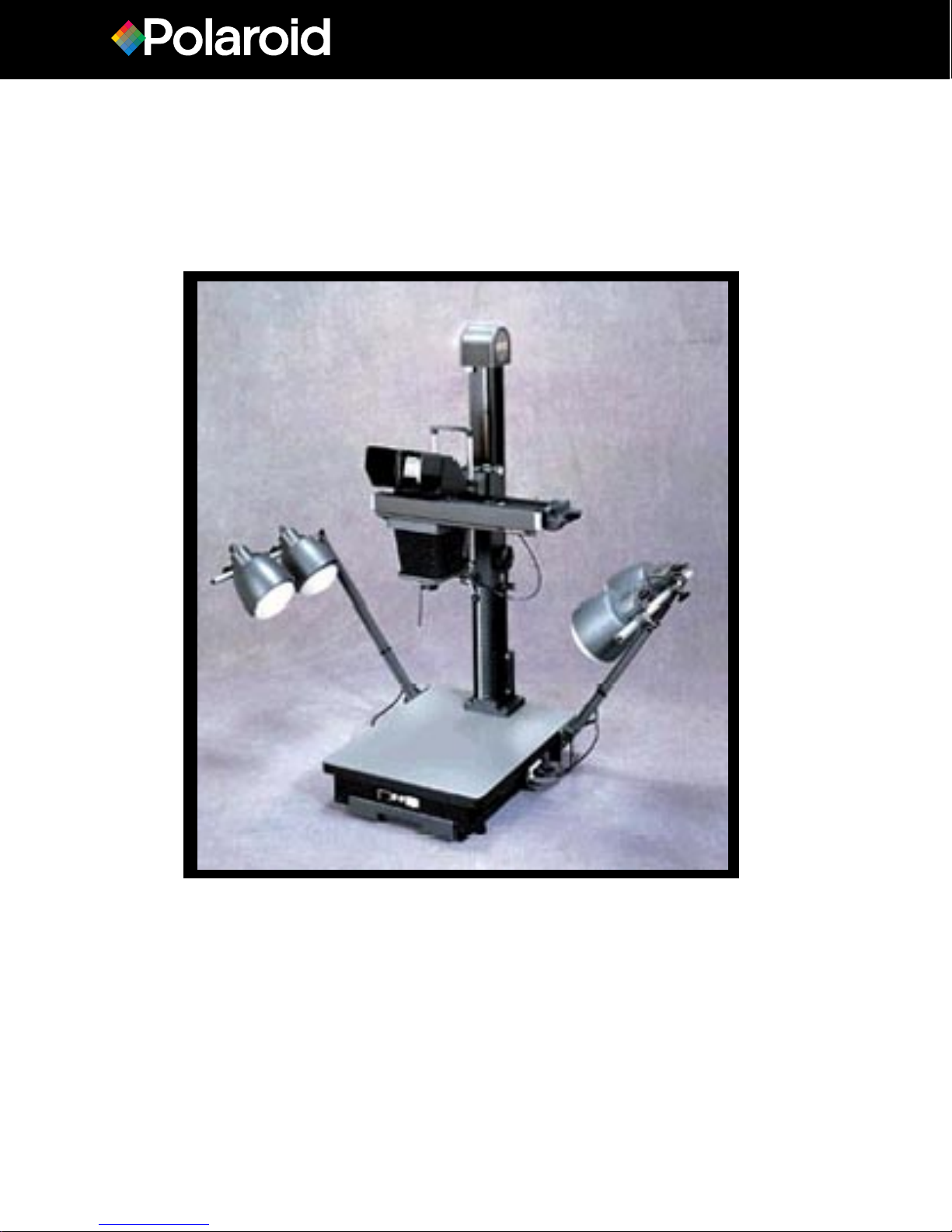
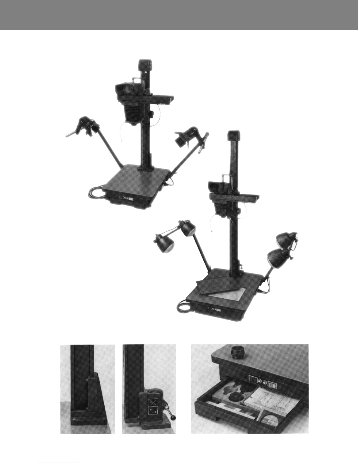
The MP4+ System is available in two
basic models (Illustration 1). The
Standard Model (left) is shown with the
optional halogen lighting; the XLR Model
(right) includes the optional tungsten
lighting and base board light box.
MP 4+ Standard Model
Total camera height: 46 in. (116cm)
Column height: 35 in. (90cm)
Baseboard area overall: 18x23 in.
(46x59cm)
Standard column/camera: 44-04
Standard baseboard 11 O-l 20VAC: 44-14
Standard baseboard 220.240VAC: 44-16
MP 4+ Model XLR
Total camera height: 66 in. (168cm)
Column height: 55 in. (140cm)
Baseboard area overall: 23x29 in.
(59x74cm)
XLR column/camera: 44-05
XLR baseboard IIO-120VAC: 44-15
XLR baseboard 220-240VAC: 44-17
The Standard Model (2-left) has a nonrotating column; the XLR Model (2- right)
has a rotating column.
Both models include a drawer below the
baseboard (3), which contains the ring assembly for the instructions and also provides a convenient storage area for the
lenses.
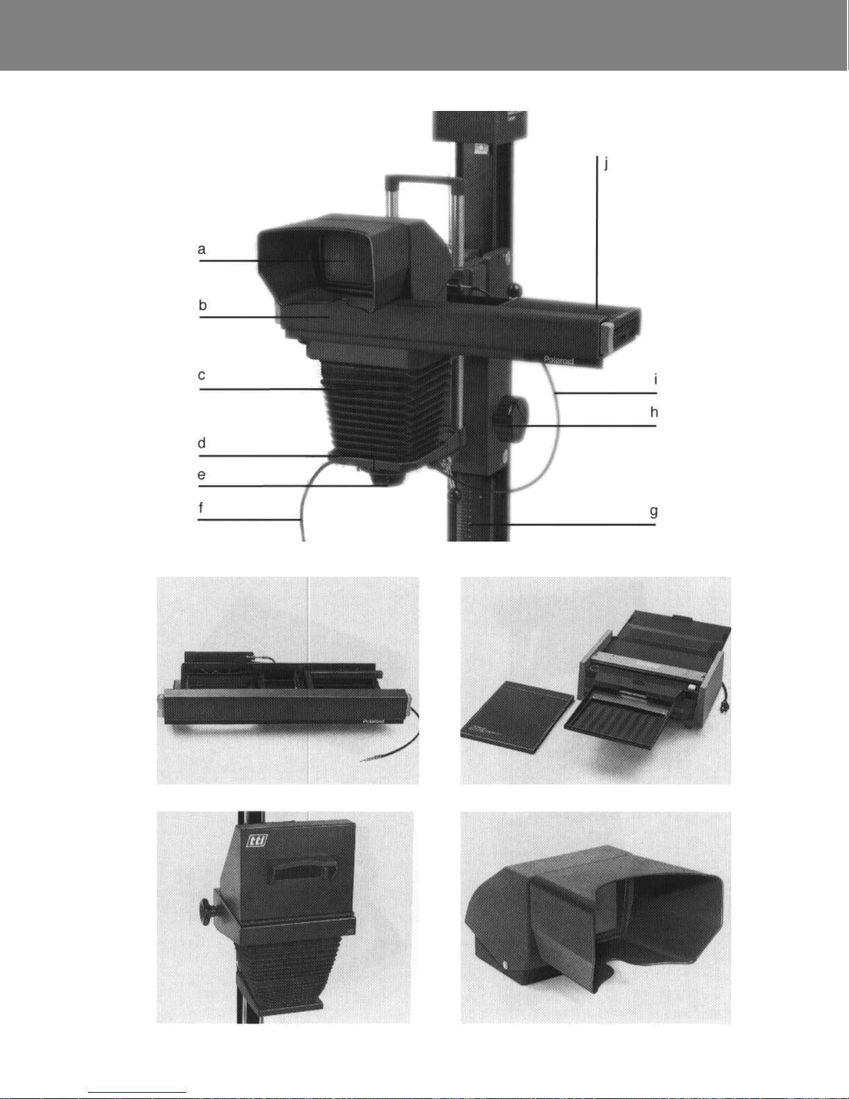
Main camera parts (4)
Reflex viewer and hood
Sliding camera head
Camera body
Shutter
Lens
“Exposure” cable release
Column scale
Camera height adjustment crank
“Pre-view” cable release
Film holder
The sliding camera head 44-41
The sliding head (5) fits on top of the
camera bellows. The ground glass and
reflex viewer are mounted on the left
side; the film holders are inserted into
the right side. This feature allows you
to view and focus the camera without
removing the film holder. You simply
slide the head into position for each
operation. The “pre-view” cable release opens the shutter as you slide
the head into the viewing position, and
closes it when you slide the head into
the picture-taking position.
a
b
c
d
e
f
g
h
i
j
Page 5

Introduction 4
TTI AVl810 8x10 camera
This camera (6) may be attached to
the column in place of the standard
MP 4+ camera, to allow the use of
Polaroid instant 8x10 films.
Polaroid 8x10 film system
This includes the 8x10 film holder
and film processor (7). The film
holder also can be used with other
8x10 camera systems.
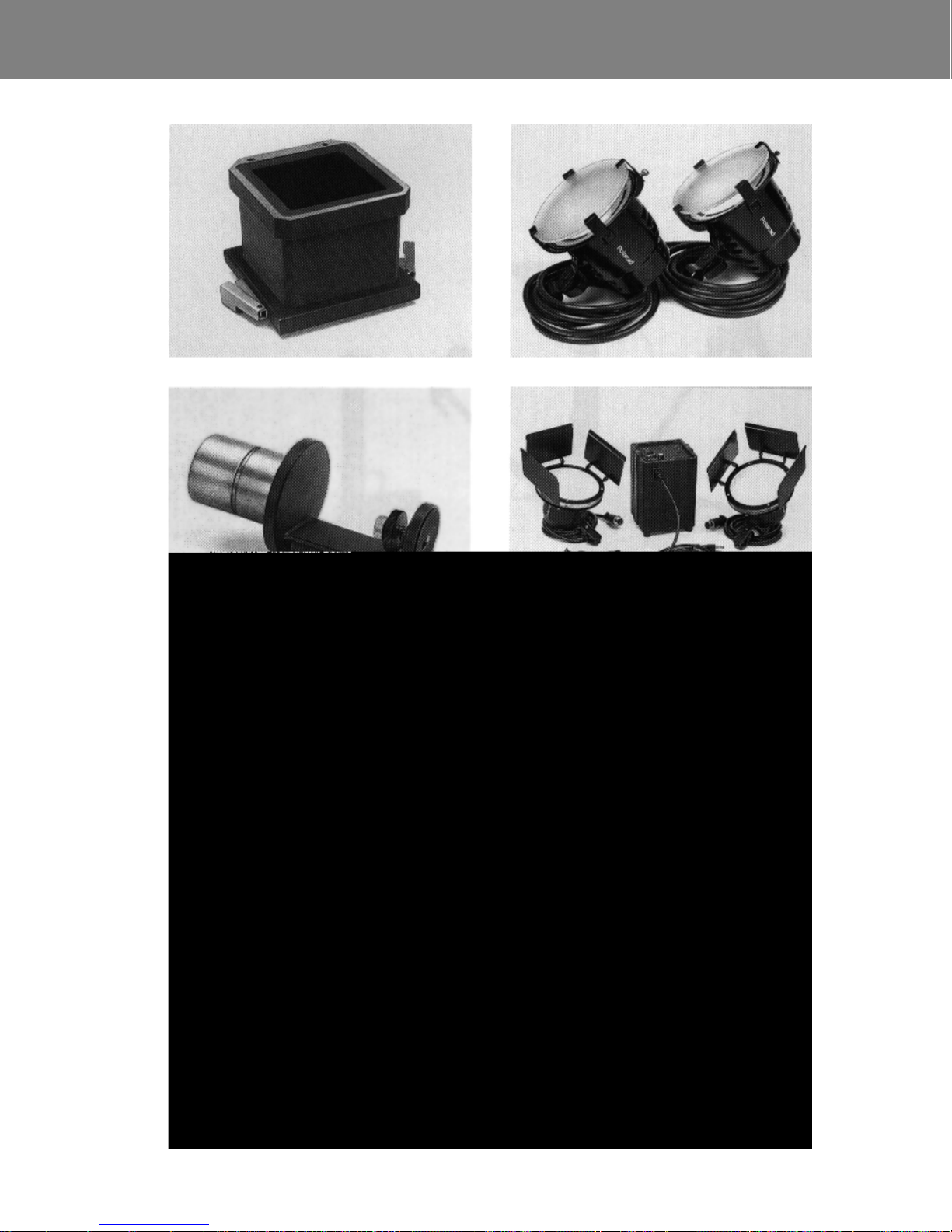
The reflex viewer 44-55
This accessory (8) attaches to the
ground glass. The viewer contains a
mirror, which directs the ground glass
image forward, rather than upward, to
make viewing and focusing much more
convenient. The viewing hood on the
front ex-cludes ambient light, so that
the image on the ground glass may be
seen most clearly.
The image you see with the reflex
viewer will appear the right way up, but
reversed from left to right. (This reversal will not, of course, appear in your
picture.)
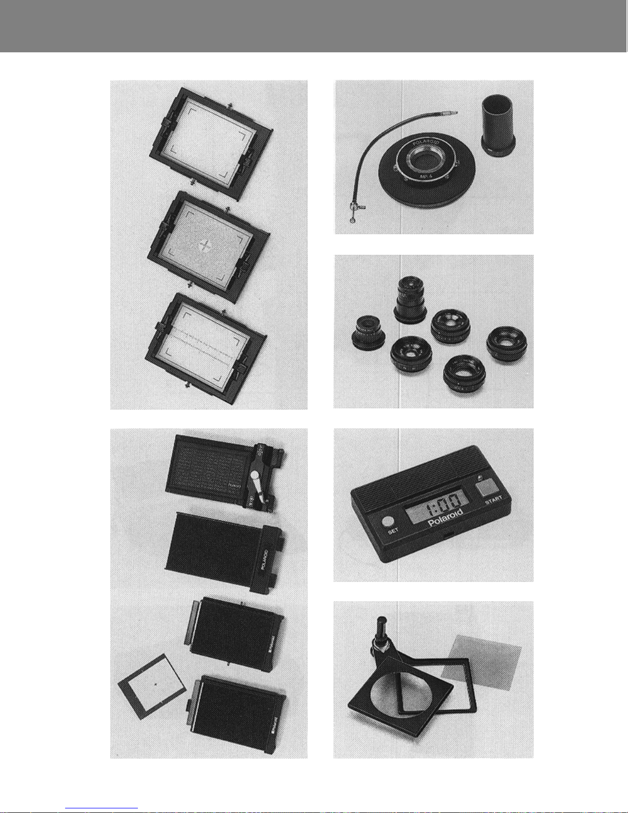
The focusing screens
The three focusing screens (9) are for
use with the Polaroid film holders described below. They also can be used
with most wet-process 4x5 sheet film
holders, and some wet-process roll film
holders. They are scribed for Polaroid
4x5 sheet film and 31/4 x 41/4 pack
film formats. The image area of 4x5
pack films extends from the right-hand
marking to about l/8 in. (3mm) beyond
the left-hand marking.
Ground glass 44-50
This is a standard ground glass
screen, for general-purpose
photography.
Aerial image ground glass 44-5 7
This ground glass has a clear-glass
circle in the center. The image can be
focused on the ground glass in the
normal way, or in the clear spot as an
“aerial image”. Instructions for use are
supplied with this ground glass.
Calibrated ground glass 44-54
It is calibrated in inches and centimeters, to measure reproduction
size.
Page 6

Introduction
5
The film holders
The MP 4+ System can be used
with the following Polaroid instant
film holders (10):
Model 545 film holder for Polaroid
4x5 sheet films
Model 550 film holder for Polaroid
4x5 pack films
MP 4+ 44-48 film holder for
Polaroid 31/4x41/4 pack films
Model 405 film holder for Polaroid
31/4x41/4 pack films
With the Model 405 film holder, the
location of the image area is not the
same as that scribed on the ground
glass. For accuracy in composition, a
framing template and instructions for
its use are provided with the holder.
The Model 545,550 and 405 film holders also can be used with a wide variety of 4x5 cameras and instruments.
In addition, a number of roll and sheet
film holders for wet-process films can
be used with the MP4+ System.
The MP4+ shutter kit 44-60
The MP4+ System uses a selfcocking, lensless shutter; the lenses
are attached to the shutter, which is
mounted in a lens board, for easy camera attachment. The shutter speeds
range from 1 sec. to l/125 sec., and
there is a “B” setting for time exposures. There is also a flash socket with
“X” synchronization. The kit (11) in-
cludes the shutter, cable release, and
microscope adapter. The microscope
adapter is attached to the shutter in
place of a lens, for photomicrography.
Instructions are provided with the kit.
Lenses for the MP4+ (12)
44-65 135m m lens; f/4.5 to f/32
44-66 105mm lens; f/4.5 to f/32
44-67 75mm lens; f/4.5 to f/32
44-68 50mm lens; f/4.5 to f/32
44-69 35mm lens; f/4.5 to f/32
44-70 17mm lens; f/4 to f/22
Film processing timer
The battery powered digital timer (13)
is designed to provide accurate timing
of film processing. It may be attached
to any convenient location on the system.
•
•
•
•
Page 7

Introduction
6
MP 4+ Filter kit 44-88
The kit (14) includes a filter holder with
two filter trays, gelatin filters and a filter
frame. The filters are intended to balance the MP 4+ tungsten and halogen
lighting for use with Polacolor films.
Filters for other purposes may be used
also, as required. Complete instructions are provided with the kit.
See Appendix for information about
other methods of attaching filters to the
MP4+ lenses.
Macro extension 44-45
The macro extension (15) is attached
to the camera between the bellows
and the camera head. It enables you
to make photographs at magnifications
up to about 27X, using the 17mm lens.
You can use two extensions to
increase the magnification range
accordingly.
See Appendix for more information.
Universal camera mount 44-85
This accessory (16) enables you to
convert the MP4+ into a 35mm copying or slide-making system. The MP4+
camera head is removed, and the
mount is attached to the column in its
place. Virtually any 35mm camera, and
many conventional cameras of other
formats, can be used on the mount.
Lighting options
Several lighting options are available
for the MP4+ System. These are ordered separately, allowing the system
to be customized for a wide variety of
applications.
Tungsten lighting
This lighting (17) is suitable for most
general purpose copystand photography. Includes four 150 watt lamps and
lamp holders. The lamps are attached
to the MP4+ lamp arms.
11O-l 20VAC system: 44-26
220-240VAC system: 44-36
Halogen lighting
This lighting (18, 19) is suitable for
most general-purpose copy-stand
photography. Includes two 300 watt
lamps and lamp holders. The lamps
are attached to the MP4+ lamp arms.
Halogen lamps produce light of the
same color temperature throughout the
life of the bulb. As a result, the film exposure and filtration requirements are
more consistent. (As tungsten lamps
age, they produce light of a lower
color temperature.)
120VAC system: 44-28
220VAC system: 44-38
240VAC system: 44-34
Page 8

Introduction 7
Electronic flash lighting
This lighting (20) is suitable for most
general-purpose copystand photography. The system includes a 400 wattsecond power supply, two lamps with
150 watt modeling lights, and a sync
cord. The lamps are attached to the
MP 4+ lamp arms.
Electronic flash produces light that is
similar to daylight, eliminating the need
for most filtration when using daylightbalanced color films.
11O-120VAC system: 44-27
220-240VAC system: 44-37
XLR Baseboard light box
The Model XLR baseboard includes a
well for an optional light box (21). The
light box contains four 14 watt fluorescent lamps; its diffusion cover produces even illumination across the entire surface. A cover fits over the light
box when it is not in use. The light box
is ideal when photographing transparent and translucent subjects. It also
can be used in combination with other
light sources, to eliminate shadows
around solid subjects.
11O-120VAC system: 44-18
220-240VAC system: 44-19
Fiberoptic lighting
The Dolan-Jenner fiberoptic lighting
system (22) is intended for photomacrography of small three dimensional
objects. The system includes a power
supply with adjustable light output, a
bifurcated fiberoptic bundle, a lens/
filter adapter for each bundle, lenses
and filters.
The power supply contains a 21V,
150W EKE quartz reflector lamp.
11O-120VAC system: 44-25
220-240VAC system: 44-35
Page 9
Introduction
1
2
3
Page 10
Introduction
4
5
6
7
8
Page 11
Introduction
9
10
11
13
12
14
Page 12
Introduction
15
16
19
20
17
18
21
22
Page 13

Assembly
1
Contents
Location
Attach column to baseboard
Model XLR
Standard Model
Assemble the camera
Attach vertical carriage to column
Attach spring housing & counterweight spring
Attach camera body to vertical carriage
Put shutter on camera
Assemble the sliding head
Attach lens to shutter
Attach the ground glass
Attach the reflex viewer
Attach the film holder adapter
Attach the lamp arms
Attach the timer
The numbers throughout the text refer to
the illustrations at the end of this chapter.
Page 14

Assembly
2
Location
The MP 4+ System should be assembled in the area where it will be
used. The system should beplaced on a
sturdy table or counter, large enough to
provide a work surface next to the baseboard. (A desk with locked storage
space is ideal, to prevent unauthorized
use.) The system must be located near
an appropriate electrical outlet. Avoid
placing the system near windows or
other sources of bright light. Be sure the
lamp arms do not extend into corridors.
DO NOT LET POWER CORD HANG
OVER FRONT EDGE OF TABLE OR
COUNTER, OR TOUCH HOT SURFACES.
UNIT MUST BE GROUNDED. POWER
CORD HAS THREE-PRONGED
GROUNDING PLUG, WHICH MUST BE
PLUGGED INTO APPROPRIATE
OUTLET. IF SUCH AN OUTLET IS NOT
ALREADY A V AILABLE, EXISTING
OUTLET MUST BE CHANGED.
DO NOT, UNDER ANY
CIRCUMSTANCES, REMOVE
GROUND PRONG FROM PLUG.*
IF EXTENSION CORD IS NEEDED,
USE CORD WITH GROUNDING PLUG*
AND SUITABLE CURRENT RATING.
CORDS RATED FOR LOWER
AMPERAGE THAN UNIT MAY
OVERHEAT. ARRANGE CORD SO
THAT IT WILL NOT BE TRIPPED OVER
OR PULLED.
* THIS APPLIES ONLY IN COUNTRIES
WITH GROUNDED ELECTRICAL
SUPPLIES.
Page 15

Assembly 3
Attach column to baseboard
Important: Before assembling the sys-
tem, check that the camera and column
serial numbers match. (The numbers
are stamped on the shipping cartons.)
Model XLR
The optional light box should be installed before attaching the column
to the baseboard. See the instructions packaged with the light box.
Position the column post as shown, with
the milled section (1-a) pointing toward
the center of the baseboard. Fasten the
post to the baseboard using the four
nuts and bolts provided. A wrench is
supplied for tightening the nuts; use a
suitable screwdriver to hold the bolts
while you are doing this. Slide the column onto the post (2) and secure it
firmly with the lock-ing knob (b).
Standard Model
Hold the baseboard in a vertical position, and the column in a horizontal position (3). The scale on the column should
face toward the center of the baseboard.
Insert the four bolts through the column
base and then through the baseboard.
Add the washers, and then the nuts.
Tighten the nuts with the wrench provided (4); use a suitable screwdriver to
hold the bolts while tightening them.
Assemble the camera
Attach vertical carriage to column
Loosen the locking lever (5-c) by at
least one full rotation.
Carefully push the lower end of the
carriage onto the column, making sure
that the two white rollers (6-d) slide
down behind the rails (e).
Lower the carriage further, until the
two white rollers at the top rest against
the top of the column (7). Slowly rotate
the height adjustment crank (f) in a
clockwise direction and, as the carriage
slowly goes down, make sure the white
rollers feed in behind the rails, as
shown.
Lower the carriage by about two
more inches, and lock it on the column
by tightening the locking lever (8-c).
Page 16

Assembly 4
Attach spring housing and
counterweight spring
Insert the spring housing into the top of
the column (9). The spring ends should
face the front. Remove the pin (10-g)
from the vertical carriage by unscrewing
it and pulling it out.
Unlock the vertical carriage, bring it all
the way to the top of the column (11),
and lock it again. Reinsert the pin, making sure that it goes through the loop
(12-h) in the spring end. Tighten the pin.
(Note: The second spring is required
only when using the 8x10 camera.)
Wind the vertical carriage down the
column until it is at an easily accessible
height (13) then lock it in position.
Warning: Never loosen or remove the
spring pin unless the vertical carriage is at the top of the column and
locked in position.
Attach camera body to vertical
carriage
Loosen the knob (14-i) until it is in a vertical position, as shown. Also loosen the
screw (j) by about three full rotations.
Orient the camera body as shown
(15), then push it all the way onto the
carriage (16). Rotate it back and forth
slightly, until you feel it click into the true
vertical position. Tighten the screw and
then the knob.
Put shutter on camera
First screw the “exposure” cable release
into its socket (17-k). Then align the
smallest of the three tabs (18-l) on the
shutter panel with the smallest of the
cutouts (m) on the camera body.
Push the shutter unit onto the camera
in that orientation, and rotate it in a
clockwise direction (19) until it comes to
a firm stop.
Caution: When there is no lens on the
shutter, the shutter blades are exposed
and unprotected. They are very delicate;
do not touch them.
Page 17

Assembly
5
Assemble the sliding head
Note the orientation of the sliding head;
the pins (20-n) fit into corresponding
holes in the camera body.
Hook the camera head onto the left side
of the camera body (21) then lower the
head carefully, taking care that the pins
engage in the holes on the camera
body.
Lock the head in place by pushing the
latch (22-o) toward the camera body.
Sliding the camera head
Depress the release button (23-p) and
slide the head all the way to the right for
viewing and focusing. Depress the other
release button to slide the head to the
left for picture-taking.
Connect the long “pre-view” cable release: Do this with the camera head in
the picture-taking position (pushed all
the way to the left). Screw the release
into the “preview” socket on the shutter
(24).
Look at the shutter from above; the
shutter blades should be fully closed
(25). Now push the head all the way into
the viewing position. The shutter blades
should be fully open (26). If the above
does not happen, adjust the plunger end
(q) of the release until the shutter func-
tions as described.
Fit the cable releases into the clamps
(27). This will prevent damage to the
shutter if the cable is accidentally pulled.
Attach lens fo shutter
Carefully screw the lens into the shutter
(28).
Attach the ground glass
One end of the ground glass frame has
two small protrusions (29-r) near its
base. Hold the frame in the left hand,
with the protrusions pointing to the left.
Slide the ground glass frame into the
camera head from the left (30). Slide it
all the way in, so that the two retainer
pins on the frame engage securely in
the two spring loops on the camera
head.
Attach the reflex viewer
The pins on the sides of the viewer fit
into the slots on the ground glass frame
(31).
Attach the film holder adapter
If using a Polaroid Model 545, 550 or
405 Film Holder, insert the U-shaped
adapter. Orient the adapter as shown
(32). Slide it all the way into the head,
so the pins (s) fit under the springs (t).
Warning: When using the sliding camera head with heavy accessories, such
as one or two macro extensions, always
lock the vertical carriage on the column
as soon as you have raised or lowered
the camera. If you do not, the camera
may begin to slide down the col-umn,
due to the extra weight.
1
2
3
4
5
Page 18

Assembly
6
Attach the lamp arms
The two lamp arms are fastened to the
left and right sides of the baseboard,
near the rear edge of the baseboard.
Orient the lamp arms so the screw faces
up (33), and the angle indicator faces
the front of the baseboard (34).
Insert the screws into the top twoholes
in the metal plate, then tighten them
firmly (35).
Orient the horizontal cross bars as
shown (36). With the MP 4+ Standard
Model, note that distance (u) is slightly
shorter than distance (v).
Attach the cross bars: Slide the cross
bars into the top of each lamp arm (37).
Rotate the bar until the groove (w)
points down and the second groove (x)
is aligned with the fastening screw.
Tighten the fastening screw to lock the
bar in place.
Angle the lamp arms: Angle them as
indicated by the two marks, and lock
them in position with the lever. This will
place the lamps in the correct position
for most general copying work. For special lighting requirements, the lamp arms
may be angled in any way desired.
The lamp arms are designed for use
with various types of lighting equipment;
see the instructions packaged with your
lights for details on locating the lamps
on the cross bars.
Attach the timer
The timer may be attached to any convenient location, such as the front of the
sliding head (38). Simply remove the
paper backing from the adhesive strip
on the back of the timer, and press it
into position.
The timer is powered by two batteries; if the timer stops working, or if the
display or tones fade, the batteries
should be replaced.
To replace the batteries, slide the door
open (39), and insert the new batteries
in the orientation (+/-) indicated inside
the compartment.
Important: After replacing the
batteries, press the SET and START
buttons simultaneously, to ensure
proper functioning of the timer.
1
2
3
4
5
Page 19

Assembly
1
3
4
5
7
8
2
6
Page 20

Assembly
9
11
12
13
15
16
10
14
Page 21

Assembly
17
19
20
21
23
24
18
22
Page 22

Assembly
25
27
28
29
31
32
26
30
Page 23

Assembly
33
35
36
37
39
34
38
Page 24

Operations
1
Contents
Film holder use
Set the film processing timer
Camera operation
Process the film
Clean the developer rollers
Lens selection
Sizing and focusing
Guide to exposure control
Exposure correction
XLR column rotation
Camera body removal
The numbers throughout the text
refer to the illustrations at the end
of this chapter.
Page 25

Operations
2
Film holder use
Instructions for use of the Models 545,
550 and 405 film holders are provided
with the holders.
MP 4+ 44-48 film holder
Load the film
Generally, the film holder should be
loaded before it is inserted into the
camera head.
Pull both sides of the latch to open the
door; the door does not open flat. Before
loading the film, check that the two steel
rollers are clean (see
Clean the
developer rollers).
Hold the film pack by the edges, not in
the center. Inset-t the pack at an angle,
then push it down into position (1).
Check that the white tabs are free,
not caught between the pack and film
holder (2).
Close and latch the door, with the end
of the black tab sticking out of the slot.
Do not pull the black tab at this time.
Remove the dark slide from the film
holder (3), then insert the holder into
the camera head.
Insert the film holder
44-48 film holder:
Slide the holder all
the way into the right side of the camera
head (4). Be sure that the two locking
pins (a) on the holder engage the
springs on the camera head.
Pull the black tab straight, all the way
out of the holder (5). A small white tab
will appear. (If not, see
No white tab?)
Model 405 film holder:
Load the film in
the usual manner, but do not pull the
black tab. Remove the dark slide.
Model 550 film holder:
Load the film in
the usual manner.
Model 545 film holder:
This holder may
be loaded while inserted in the camera
head.
The Model 545,550 and 405 film holders
fit under the U-shaped adapter (see the
Assembly Chapter).
Slide the film holder under the
adapter, as shown (6). Push it all the
way in, so it is firmly seated.
Pull the black tab out of the Model
405 film holder.
1
2
3
4
5
Page 26

Operations 3
Set the film processing timer
Press and hold the SET button (7) until
the correct processing time is displayed
(see the film instructions for recommended times). The timer will always
return to this setting after a processing
cycle.
To reset the timer to a new time:
To reset it to a longer time than is displayed, simply press and hold the SET
button until the new time is displayed.
To reset it to a shorter time:
Press the SET and START buttons
simultaneously. The preset time is
cancelled and zero is displayed.
Press and hold the SET button until the
new time is displayed.
Camera operation
Determine the approximate reproduction
scale: Measure the original subject (or
area to be photographed), and the final
size needed. Select the lens to be used,
and attach it to the shutter. (See
Lens
selection.
)
Set the lens at its largest aperture
(lowest f-number). This will provide the
brightest possible image for focusing on
the ground glass.
Turn on the power: Press the switch on
the front of the base-board (8). Then, if
necessary, turn on the lights.
CAUTION: TURN OFF LIGHTS AND
POWER WHEN NOT IN USE. IF SYSTEM WILL NOT BE USED FOR AN
EXTENDED PERIOD OF TIME, UNPLUG FROM ELECTRICAL OUTLET.
GRASP PLUG NOT CORD
AND PULL TO DISCONNECT.
Slide the camera head into the viewing
position: Depress the button (9-b) and,
while holding it in, push the head all the
way to the right, so that the reflex
viewer/ground glass is above the lens.
Place the original subject on the baseboard and frame the image: If you are
using a ground glass only, the image on
this will appear upside down. If you are
using the reflex viewer, the image will
appear right side up, but reversed left to
right.
1
2
1
2
3
4
Page 27

Operations 4
Size and focus the image: Turn the
locking lever (10-c) in a counter-clockwise direction, to release the carriage.
While viewing the image on the ground
glass, turn the crank (d) to adjust the
height of the camera until the image on
the ground glass is about the required
size.
Adjust the focusing knob (11-e) until
the image is sharp. At this point, the
image may not be exactly the correct
size. Adjust the camera height again,
and refocus. You may have to repeat
this several times, until the image is
both exactly the right size and also in
focus. (See also
Sizing and focusing.)
Finally, lock the carriage in position by
turning the locking lever in a clockwise
direction, without excessive force.
Center the subject on the baseboard
in the way you want to reproduce it:
Remember to use the ground glass
marking that is intended for the film
format you are using.
Slide the camera head into the picturetaking position: Depress the button and,
while holding it in, slide the head all the
way to the left (12) to place the film
holder above the lens.
If using a Model 545 film holder,
pull out the envelope (13); with a
Model 550 film holder, pull out the
dark slide (14).
Set shutter speed and lens aperture
for correct exposure: Use the exposure
guide supplied with the lights. (See also
Guide to exposure
control.)
To set the shutter speed, turn the silver ring to place the indicator (15-f) at
the desired speed. It will click into position. Never set the indicator between
shutter speeds.
To set the lens aperture, turn the
lens ring to place the desired aperture
opposite the dot (g). The ring will click
into position. The lens may be set
between full aperture settings.
Make the exposure: Gently depress the
plunger on the cable release (16).
5
6
7
8
10
Page 28

Operations
5
Process the film
CAUTION: IF FILM HOLDER IS AT
SAME HEIGHT AS LIGHTS, TURN
THEM OFF BEFORE PULLING FILM
TABS, TO PREVENT BURNS AND
FOGGING FILM.
Pull the white tab straight, all the way
out of the film holder (17). A large yellow
tab will appear. (if not, see No yellow
tab?)
Grip the yellow tab firmly, and pull it
straight, at moderate speed, all the way
out of the holder (18).
Press the START button on the film
processing timer (19).
At the end of the processing time,
separate the print from the negative,
starting at the end nearest the yellow
tab (20). Information on the handling
of prints and negatives is in the film
instructions. See Caution.
Caution
The Polaroid instant film process uses a
caustic paste. Avoid contact with skin,
eyes and mouth and keep away from
children and animals. If you get some
paste on your skin, wipe it off immediately and wash with water to avoid
an alkali burn. If eye or mouthcontact
occurs, quickly wash the area with
plenty of water and see a doctor. Keep
discarded materials away from children,
animals, clothing and furniture.
No white tab?
Carefully open the door and, without
moving the film pack, push the white tab
out (21). Then close and latch the door.
No yellow tab?
Do not pull another white tab. Instead,
carefully open the holder far enough to
get a finger on top of the film pack to
hold it down ( 22) Grasp the topmost
yellow tab, and gently pull it all the way
out of the holder (23) and discard it.
Inspect the rollers and clean them if
necessary (see
Clean the developer
rollers).
Close and latch the door, with
the next white tab sticking out.
Clean the developer rollers
Dirt on the developer rollers can cause a
variety of problems, such as repeated
spots on pictures and jammed film.
Inspect the rollers before loading film,
and clean them as follows.
With both hands, lift the steel loops,
and remove the roller assembly (24).
Clean both rollers with a soft, lint-free
cloth, dampened with water if necessary
(25). Or, hold the roller assembly under
clean running water. Rotate both rollers
as you clean and inspect them. Note
that one roller turns more easily than the
other. Never scrape the rollers with anything metallic, nor with your fingernail,
and never attempt to disassemble the
rollers. Also clean the film tab slot (28).
Then replace the roller assembly.
1
2
3
4
Page 29

Operations
*
6
Lens selection
Each MP 4+ lens is designed for
reproductions within a specific range.
This chart shows the approximate
ranges; see the
Appendix Chapter
for
more details.
Lens Minimum Maximum *
135mm 10% 1.2x
105mm 20% 1.5x
75mm 1.5x 3x
50mm 1.5x 5x
35mm 5 x 7.5x
17mm 10x 20x
Use one or two macro extensions
for additional magnification.
Sizing and focusing
General rule: To
increase
the size of the
image on the ground glass, lower the
camera and lengthen the bellows (27).
To
decrease
the size of the image, raise
the camera and shorten the bellows
(28).
Reductions:
First, adjust the camera
height to get the approximate image
size required. Then, adjust the bellows
for sharp focus. Magnifications: First,
adjust the bellows to get the approximate image size required. Then adjust
the camera height to attain sharp focus.
Camera column scale:
When the
column scale is read at the point
indicated (29), it represents the film
plane to baseboard distance.
Bellows scale:
The scale on the left
focusing column represents the bellows
extension, when it is read at the point
indicated (30).
These scales can be used in conjunction with the tables in the
Appendix
Chapter
to set the camera for specific
reproduction ratios.
Note:
If the
exact
reproduction ratio
must be documented, place a ruler on
the baseboard and photograph it with
the original subject (31). Be sure the
ruler is in the same plane as the original
subject.
Page 30

Operations 7
Guide to exposure control
Exposure is the amount of light that
reaches the film through the lens. It is
controlled by the length of time the
shutter is open (shutter speed) and
the size of the opening in the lens
(lens aperture).
The shutter stays open for the length
of time indicated on the ring. The numbers signify fractions of a second; thus,
60=1/60 sec., 4=1/4 sec., 1-1 sec., etc.
Each shutter speed will admit either
twice as much or half as much light
as the one next to it on the ring.
The lens opening can be made larger
or smaller. The size of the opening is
measured in f-numbers, which are
marked on the lens ring. The highest
f-number in-dicates the smallest opening; the lowest f-number indicates the
largest opening.
Each lens opening will admit either
twice as much or half as much light as
the one next to it on the ring. Thus,
changing from f/11 to f/8 will double the
exposure; changing from f/11 to f/16 will
cut the exposure in half.
Exposure correction
To increase exposure (make pictures
lighter), use a longer exposure time
(slower shutter speed), or a larger lens
aperture (lower f-number). To decrease
exposure (make pictures darker), use a
shorter exposure time (faster shutter
speed), or a smaller lens aperture
(higher f-number).
Shutter speeds
125 60 30 15 8 4 2 1
o Darken / Lighten o
Lens openings
4.5 5.6 8 11 16 22 32
o Lighten / Darken o
Note:
When using an electronic flash
system, the shutter is set at a specific
speed. A control on the power supply is
used to adjust the light output of the
lamps to control the exposure. (See the
instructions supplied with the flash unit.)
Page 31

Operations
XLR column rotation
The column of the Model XLR can be
rotated through an angle of 180 degrees, so that the camera is aimed
toward the floor, rather than at the
baseboard. This position can be useful if
you wish to photograph something that
cannot be easily accommodated on the
baseboard.
Warning: Before you rotate the column,
be sure to place an object, or objects, of
adequate weight on the baseboard, to
prevent the camera from falling over.
If you have a light box in the baseboard,
remove the glass cover, and replace it
with the baseboard insert. Never place
heavy objects on the glass cover.
To rotate the column, loosen the
column locking lever (32-h), turn the
entire column to the desired position,
and lock the lever again. Leave the
weights on the baseboard (33) until the
camera head has been returned to its
normal position over the baseboard.
Camera body removal
You can remove the camera body
and use another camera on the MP 4+
column (such as the 8 x 10 camera or a
35mm camera, using the 44-85 Universal camera mount). These accessories
are de-scribed in the
Introduction
Chapter.
To remove the camera body, loosen
the locking knob (34-i) until it is in a vertical position. Then loosen the retainer
screw (j) by about three full rotations.
Pull off the camera body as shown (35).
Before replacing the camera body, be
sure the locking knob and retainer screw
are loosened. Push the camera body on
all the way, tighten the retainer screw
and then the locking knob.
8
Page 32

Operations
1
2
5
6
3
4
7
8
Page 33

Operations
9
10
13
14
11
12
15
16
Page 34

Operations
17
18
21
22
19
20
23
24
Page 35

Operations
25
26
28
27
30
Page 36

Operations
31
32
35
33
34
Page 37

Troubleshooting
1
Contents
Picture faults and probable causes
MP 4+ care and maintenance
Warranty
Service
Page 38

Troubleshooting
2
Picture faults and probable causes
Repeated, evenly-spaced spots:
Due to dirt on the steel developer
rollers.
Missing corners or orange-red marks
along edges:
Caused by pulling the
yellow tab out at an angle.
Oblong in print:
The white tab was not
pulled all the way out. When the yellow
tab was pulled, that white tab was pulled
back into the film holder.
Many small white specks:
Caused by
pulling the yellow tab out too fast. This
also can cause pink lines, streaks or
blotches on color prints.
Muddy-looking print:
The print was not
processed for a long enough time.
Underprocessed color prints may be
brownish pink.
Broad streak or curtain-shaped mark:
Due to hesitation or stopping while
pulling out the yellow tab.
Very light image or none at all:
The
film was fogged or extremely overexposed. See also
Operation:
Guide to
exposure control.
Nearly black or solid black image:
Caused by insufficient or no exposure.
Be sure the black tab and dark slide
have been removed, and that the
electronic flash fired (if used). See also
Operation:
Guide to exposure control.
See the instructions supplied with the
film holders for additional information.
Page 39

Troubleshooting 3
MP 4+ care and maintenance
Polaroid film holders:
The two steel
rollers in each film holder must be kept
absolutely clean, to prevent spots on
pictures and jammed film. Always check
the rollers before loading film; clean
them with a damp cloth as explained
in the instructions packaged with the
holder.
Lenses and shutter:
Never touch the
surface of a lens. You can remove fingerprints and smudges by wiping gently
with lens tissue or a soft, lint-free cloth.
The elements in each lens are precisely
mounted and aligned by the manufacturer, and should be removed only by
a qualified camera repair technician.
The shutter is lifetime lubricated; do not
attempt to either oil or adjust it.
Reflex viewer:
The reflex viewer contains a front-surfaced mirror, which is
easily scratched or damaged. Do not
touch it. Remove fingerprints with a soft,
lint-free cloth; use an antistatic brush to
remove dust.
Moving parts:
Never attempt to lubricate any part of the assembly. All
moving parts are lubricated at the factory, for smooth performance over a long
period of time. Keep all parts of the
camera clean, and cover the entire system when it is not in use.
Spare parts:
For information on parts
that may be replaced by the camera
owner, and for a supply of such parts,
please contact the Polaroid Resource
Center or the nearest Polaroid Office.
CAUTION: TO AVOID ELECTRICAL
SHOCK HAZARDS, DO NOT ATTEMPT
TO OPEN SWITCH UNIT OR OUTLET
UNITS. IF SERVICE OR REPAIR
WORK IS REQUIRED, CONTACT
AUTHORIZED SERVICE CENTER.
Page 40

Troubleshooting
4
Warranty
This product has been thoroughly tested
and inspected before ship-ment. All
parts are guaranteed against defects in
materials and workmanship for one full
year from the date of original purchase.
During this period any such defects will
be remedied by Polaroid Corporation
without charge, except for transportation
costs. The warranty does not include the
bulbs, which are covered by the bulb
manufacturers.
U.S.A. only:
THIS WARRANTY EXCLUDES ALL
CONSEQUENTIAL DAMAGES.
Outside U.S.A.:
THIS WARRANTY DOES NOT AFFECT
YOUR STATUTORY RIGHTS.
Service
Units damaged by accident or mishandling, or worn from normal use will be
promptly repaired at a reasonable
charge. Pack the unit carefully in its
original shipping carton or other sturdy
container with plenty of padding, and
ship it, prepaid and insured, to the nearest Polaroid Service Center.
Page 41

Appendix
1
Contents
Depth of field
Camera settings for range of
reductions and enlargements
Selecting the lens
Exposure strip
Alternate filter attachment methods
Page 42

Appendix
2
Depth of field
The tables below and on the
following page show the depth of
field for each lens aperture, for a
range of reproduction scales.
The indicated depth applies to
Polaroid prints; the depth of field
for negatives is less.
Page 43

Appendix 3
Page 44

Appendix 4
Camera settings for range of
reductions and enlargements
The table below indicates the correct
column and bellows settings for reductions. The table on the facing page is
used for enlargements; this table includes the bellows settings only. With
reduction work, the image is sized by
adjusting the bellows, then focused by
adjusting the camera
height.
Important: The column settings are
used for flat subjects placed directly on
the baseboard. If photographing threedimensional subjects, or subjects that
are raised above the baseboard, the
camera must be raised to ensure
correct focus.
To increase the magnification:
Lower the camera and lengthen
the bellows (1).
To decrease the magnification:
Raise the camera and shorten the
bellows (2).
Turn the crank to raise o r lower
the camera (3); the column setting
is read at the point shown (4).
Turn the knob (5) to adjust the
length of the bellows; read the
bellows extension at the point
shown (6).
•
•
•
•
1. Column must be rotated to increase film-to-subject distance; available on XLR Model only.
2. Requires XLR Model.
Page 45

Appendix
5
Page 46

Appendix
Selecting the lens
Each of the MP 4 lenses can be used
for a range of reproduction sizes. The
MP 4 macro extension provides
increased magnification (two extensions
can be used, if desired).
Often you have more than one lens/
macro extension option for a given
magnification. In most cases, if you
have a choice of lenses, you should
use the lens of longer focal length.
This will provide more working space
between the lens and subject.
Four MP 4 set-ups for 3X magnification
are shown:
135mm lens with two macro extensions
(7). This camera set-up provides the
most working space between the lens
and subject, but may be awkward to
use, due to its size. The distance
between the view-finder and the lens
will be about 26
1
/2 in./68cm. Also, when
using two macro extensions, the
“preview” cable elease must be
disconnected and the shutter operated
manually for viewing and focusing.
•
•
•
•
105mm lens with one macro extension
(8). With this set-up, there is still ample
working space between the lens and
subject, and the camera is easier to use.
This may be the best option for 3X magnification.
75mm lens alone (9). This set-up provides less working space below the
lens, making it more difficult to properly
illuminate some subjects. If necessary,
the subject may be raised above the
baseboard for easier lighting.
50mm lens alone (10). With this set-up,
there is very little space between the
lens and subject (less than 2 in./5cm.)
This will severely limit subject illumination. Note that the subject must be
raised above the baseboard for proper
focus.
6
Page 47

Appendix
Exposure strip
The exposure guides supplied with the
MP 4 lights are intended for use when
the lights are positioned for general
copy work. The recommended exposure
settings may be inaccurate when using
other lighting arrangements or mixed
lighting, when photographing highly reflective subjects and for some specialized applications. In these situations,
you can make a series of exposures on
a single sheet of film to determine the
correct exposure. Follow these steps:
If using a Model 545 film holder (11) pull
out the film envelope and check for the
negative in the usual manner before
making the first exposure.
With a Model 550 film holder (12), pull
the dark slide out to the line before making the first exposure.
With a Model 405 film holder (13), you
must remove the reflex viewer to allow
clearance for the dark slide. Pull the
slide out to the line before making the
first exposure.
Estimate the correct exposure, and set
the camera for two or three stops less
than that exposure. For example, if you
think the correct exposure time will be
1/2 sec., set the shutter at 1/8 or 1/15
sec.
Pull out the dark slide (or film envelope)
and make an exposure.
Push the dark slide about 3/4 in.
(2Omm) back into the film holder. Then
make a second exposure at the same
shutter speed.
Push the dark slide another 3/4 in.
and double the exposure time.
Continue pushing in the dark slide, making incremental exposures at twice the
previous exposure time until the dark
slide is all the way back in the film
holder.
Process the film. You will have a photograph divided into steps with successively longer exposure times. Each step
will show an exposure time twice as
long as the previous step and half as
long as the following step. In the sample
exposure strip (14) five separate exposures were made: 1/15 sec., 1/15 sec.,
1/8 sec., 1/4 sec. and 1/2 sec.
Step a received a single exposure
of 1/15-sec.
Step b received two 1/15-sec.
exposures; the total exposure time
was 1/8 sec.
Step c received three exposures (1/15 +
1/15 + I/8 sec.); the total exposure time
was 1/4 sec.
Step d received four exposures (1/15 +
1/15 + 1/8 + 1/4 sec.); the total exposure
time was 1/2 sec.
Step e received five exposures (1/15 +
1/15 + 1/8 + 1/4 + 1/ 2 sec.); the total
exposure time was 1 sec.
•
•
•
•
•
•
•
•
1
2
3
4
5
6
7
Page 48

Appendix
Alternate filter attachment methods
You can use any of three types of
adapter rings to attach glass filters to
the MP 4 lenses:
A set-screw ring slips loosely over the
front of the lens mount and is
held in place by a set-screw
A slip-on ring slips tightly over the
front of the lens mount and is held
in place by friction
A threaded ring screws into the
front mounting threads of the lens
A step-up ring enables you to use
the Series 6 filters with the 35mm
and 17mm lenses as well as with
the other MP 4 lenses.
The table below lists the
specifications for Tiffen adapter rings
and glass filters for the MP 4 lenses.
(Some of the adapter rings may not be
readily available.) The MP 4 filter kit for
electrophoresis gel photography
(PID # 616364) includes a threaded
filter holder and three glass-mounted
filters. The holder fits the 135, 105
and 75mm lenses.
Tiffen adapter rings
Lens Filter size Set-screw Slip-on Threaded
135mm Series 6 42 SS 6 42SO6 39.5 M 6
105mm
75mm
50mm
35mm Series 5 28.5 SS 5 28.5 SO 5 27 F 5
17mm Series 5 24 SS 5 24SO5 22.5 F 5
“Tiffen” is a registered trademark of the Tiffen Manufacturing Company.
8
•
•
•
•
Page 49

Appendix
1
2
3
5
4
6
Page 50

Appendix
7
8
9
10
Page 51

Appendix
11
14
13
12
Page 52

MP 4 Electronic Flash System
English
Page 53

English
Electronic flash system
The electronic flash lighting for the
Polaroid MP 4 System is intended for
general-purpose photography. The lighting is designed to provide even illumination for photographic reproductions
ranging from maximum reductions to
magnifications up to about five times
life-size.
Generally, the lamps are attached to
the MP 4 lamp arms, but also may be
used on separate light stands.
The lamps have a modeling light that
requires a 150-watt halogen bulb
(ESPl5OW for 110/120-volt units;
EYEl5OW for220/240-volt units). Replacement bulbs may be purchased
from your Polaroid MP 4 dealer or the
nearest Polaroid Office.
1
NEVER USE LAMPS OF A HIGHER
WATT AGE THAN RECOMMENDED.
Page 54

English
2
Assemble the lighting
The lamp arms and cross bars should
be assembled as described in the
Assembly Chapter of the main MP 4
instruction manual. The numbers
throughout the text refer to the
illustrations at the end of this booklet.
The lamps should be positioned on
each cross bar in the locations shown
in Illustration 1.
1
Place the power supply next to the
baseboard, so the controls will be
accessible and visible.
2
Loosen the knob on the lamp
mount, and slide the lamp into its
correct location on the cross bar
(2).
3
Loosen the locking lever (3-a) and
adjust the angle of each arm so
the indicators (b) are aligned. This
will place both lamp arms at the
same angle and distance from the
baseboard.
4
Tilt the lamps so that they are
aimed at the baseboard at about a
45 angle (4). Tighten the mount-ing
knobs firmly. The barn doors can be
opened or closed (5) as needed to
illumin-ate subjects of various sizes.
5
Run the lamp cords down the
sides of the lamp arms, and clamp
them at the top and bottom, using
the clips provided (6).
The power supply controls (8)
•
Modeling light power switch:
Press 1 to turn on, or 0 to turn off.
This light is used for focusing.
•
Main power switch:
Press 1 to turn on,
or 0 to turn off. Light output setting: Allows youto adjust the amount of light
fromthe flash. The output is shown in
watt-seconds. 400 watt-seconds is full
power; 50 watt-seconds is 1/8 power.
•
READY/TEST switch:
When the
green light is on, the flash is ready
to fire. Pressing the switch will fire
the flash without exposing the film.
There is a circuit breaker on the
bottom of the power supply. Turn off the
power before re-setting. If the breaker
trips repeatedly, contact an Authorized
Service Center for assistance.
Check that the power supply is turned
off, then plug the power cord into a
black outlet on the baseboard; use the
black switch to turn the outlet on and off
(9) 11O-12OV system;
(IO) 220-240V system.
ALWAYS TURN OFF POWER WHEN
SYSTEM IS NOT IN USE. IF SYSTEM
WILL NOT BE USED FOR EXTENDED
PERIOD OF TIME, UNPLUG POWER
CORD FROM ELECTRICAL OUTLET.
GRASP PLUG NOT CORD AND PULL
TO DISCONNECT.
6
Plug the sync cord into the
X-socket on the power supply, and
then into the shutter (7).
Page 55

English
3
Lighting options
When the electronic flash lights are
aligned as shown in illustra-tion 4,
they will provide even illumination of
the entire base-board. This is most
important when photographing large
subjects, and when using highcontrast films.
When photographing small subjects,
the barn doors can be closed partway
to direct the light to a smaller area and
to prevent stray light from reaching
the lens.
Note: The exposure guide in-cluded
with the lights is based on a standard
alignment; if the lights are positioned in
a different manner, the recommended
exposure may require adjustment.
WARNING:
THE LAMPS GET HOT. DO NOT
TOUCH THEM OR PLACE THEM
EXCESSIVELY CLOSE TO CAMERA
BELLOWS, DRAPES, CLOTHING OR
OTHER FLAMMABLE MATERIALS.
Replacing the modeling bulb
1
Turn off the power supply and disconnect the power cord from the outlet on
the baseboard. Re-move the lamp from
the cross bar.
2
Loosen the four screws on the back of
the reflector (11) and remove the front
cover.
3
To remove the bulb, press down and
turn it in a counter-clockwise direction.
4
Keep the bulb in its protective wrapping
while installing it. Never touch the bulb
with your bare fingers; fingerprints on
the bulb can greatly reduce bulb life.
5
To insert the new bulb, align the pin on
the base with the slot in the bulb socket
(12). Press the bulb down into the
socket, and turn in a clockwise direction.
6
Replace the front cover.
NEVER OPERATE LAMP WITHOUT
FRONT COVER IN PLACE. TO AVOID
ELECTRICAL SHOCK HAZARDS, DO NOT
IMMERSE UNIT IN WATER OR OTHER
FLUIDS. IF SERVICE OR REPAIR WORK IS
REQUIRED, CONTACT AUTHORIZED
SERVICE CENTER.
!
TURNING POWER SWITCH OFF DOES
NOT DIS-CONNECT UNIT FROM
ELECTRICAL SUPPLY. LOCATE POWER
SUPPLY NEAR OUTLET SO IT CAN BE
UNPLUGGED. DO NOT OPERATE UNIT
WITH DAMAGED CORD, OR UNIT WHICH
HAS BEEN DROPPED OR DAMAGED,
UNTIL IT HAS BEEN EXAMINED BY
AUTHORIZED SERVICE
REPRESENTATIVE.
Page 56

English
1
4
2
3
5
6
4
7
Page 57

English
8
5
9
10
11
12
 Loading...