

Page 1

Repair Manual
Americas Business Center
Technical Services
201 Burlington Road
Bedford MA 01730
TEL: 1.781.386.5309
FAX: 1.781.386.5988
Miniportrait 204/404
May 1997
Page 2

Repair Manual Model 204/404 MiniPortrait Camera
Contents
Purpose of this Manual..................................... 3
Organization of this Manual.............................. 3
Other Documents Required for Repair............. 3
List of Illustrations............................................. 4
1. Description and Operation .......................... 5
2. Troubleshooting .......................................... 23
3. Parts Replacement...................................... 34
4. Schematics.................................................. 57
About this Manual
This manual applies to both the Model 204 and 404 cameras. Differences
between these two models will be noted throughout the document.
2
Page 3

Repair Manual Model 204/404 MiniPortrait Camera
Purpose of this Manual
This manual is intended as a reference guide for Polaroid and Polaroid
authorized technical personnel repairing the Polaroid Model 204/404
MiniPortrait Camera.
Organization of this Repair Manual
Description and Operation. General information about camera features,
capabilities, applications and operating instructions.
Troubleshooting. Function tables for diagnosing problems.
Parts Replacement. Step-by-step procedures for replacing system assemblies
and components.
Schematics. Electronic schematics to isolate problems and assist in component
replacement.
Other Documents Required for Repair
In addition to this manual, repair requires the use of the Polaroid Model 204/404
MiniPortrait Camera Parts Catalog.
3
Page 4

Repair Manual Model 204/404 MiniPortrait Camera
List of Illustrations
Section 1. Description and Operation
Figure 1-1 Rear (Operational) View .......................................................................8
Figure 1-2 Front View ............................................................................................8
Section 3. Parts Replacement
Figure 3-1 Removing the Front/Rear Housing .......................................................36
Figure 3-2 Unplugging the Electrical Connectors ..................................................37
Figure 3-3 Replacing the Aiming Light....................................................................40
Figure 3-4 Adjusting the Aiming Light.....................................................................40
Figure 3-5 Replacing the Strobe Assembly ............................................................41
Figure 3-6 Removing the Shutter Assembly............................................................42
Figure 3-7 Replacing the Solenoid(s).....................................................................44
Figure 3-8 Solenoid/Shutter Blade Orientation ......................................................45
Figure 3-9 Removing the Baffle .............................................................................47
Figure 3-10 Removing the Pull Film Switch ...........................................................47
Figure 3-11 Checking Switch Position with Go/No-Go Gauge................................48
Figure 3-12 Replacing the Load Film Sensor ........................................................50
Figure 3-13 Logic Board Screws and Connectors .................................................52
Figure 3-14 Power Board Screws and Connectors.................................................54
Figure 3-15 LCD Display Board Removal...............................................................55
Figure 3-16 Replacing the Capacitor......................................................................56
Section 4. Schematics
Logic Board.............................................................................................................58
Power Board ...........................................................................................................59
Harness Diagram....................................................................................................60
4
Page 5

Repair Manual Model 204/404 MiniPortrait Camera
Section 1. Description and Operation
Important Safety Instructions ................................................................................6
A. General Description..........................................................................................7
B. Camera Components........................................................................................8
C. Camera Features............................................................................................10
D. Operating Instructions....................................................................................13
(1) Work area requirements...........................................................................13
(2) Preparing the camera for making ID photos.............................................13
(3) Making ID photos .....................................................................................16
(4) Programming the camera.........................................................................19
5
Page 6

Repair Manual Model 204/404 MiniPortrait Camera
Important Safety Instructions
When using the camera, always follow these basic safety precautions:
• Read and understand all instructions before setting up and using the system.
• Close supervision is necessary when any appliance is used by or near
children. Do not leave the camera unattended while in use.
• Do not operate the camera with a damaged cord, or when it has been
dropped or damaged, until it has been examined by a qualified service
person.
• Position the cord so that it will not be tripped over, pulled, or in contact with
hot or sharp surfaces.
• If an extension cord is necessary, a UL recognized grounded cord with a
rating at least equal to that of the camera should be used.
• Always turn the camera OFF before unplugging.
• Always unplug the camera from the electrical outlet when not in use, and
before cleaning and servicing. Never pull the cord from the outlet. Grasp
and pull the cord from the outlet to disconnect.
• To reduce the risk of electrical shock, do not immerse the camera in water or
other liquids and do not operate outdoors in inclement weather.
CAUTION
The film used by this camera contains a caustic jelly that is safely
packed inside the film pack. If you should accidentally get some of
this jelly on your skin, wipe it off immediately and wash the area with
plenty of water as soon as possible. Under all circumstances, keep
the jelly away from the mouth and eyes. Keep discarded materials
out of reach of children and animals, and out of contact with clothing
and furniture, as discarded materials still contain caustic jelly
residue.
6
Page 7

Repair Manual Model 204/404 MiniPortrait Camera
A. General Description
The Polaroid Model 204/404 MiniPortrait Camera is a new, optical cut-and-paste
camera that features the unique combination of programmability, low cost, and
exceptional ease-of-use.
Features include programmable LCD graphic display of step-by-step operational
prompts, power-on memory, battery capability, counters for strobe flashes and
packs used, key switch, tripod mount, converging light rangefinder, sync circuit
system with ON/OFF switch, and removable film holder for black-and-white and
color films.
The system consists of a camera head, camera base and AC/DC adapter. The
camera head pivots so that it can swing down into the camera base for storage
and transport, and swing up for picture-taking.
The camera can be positioned either 40 inches from the subject for a larger
head size, or 60 inches from the subject for a smaller head size. At 60 inches, a
supplementary lens is required for proper focus.
7
Page 8
Repair Manual Model 204/404 MiniPortrait Camera
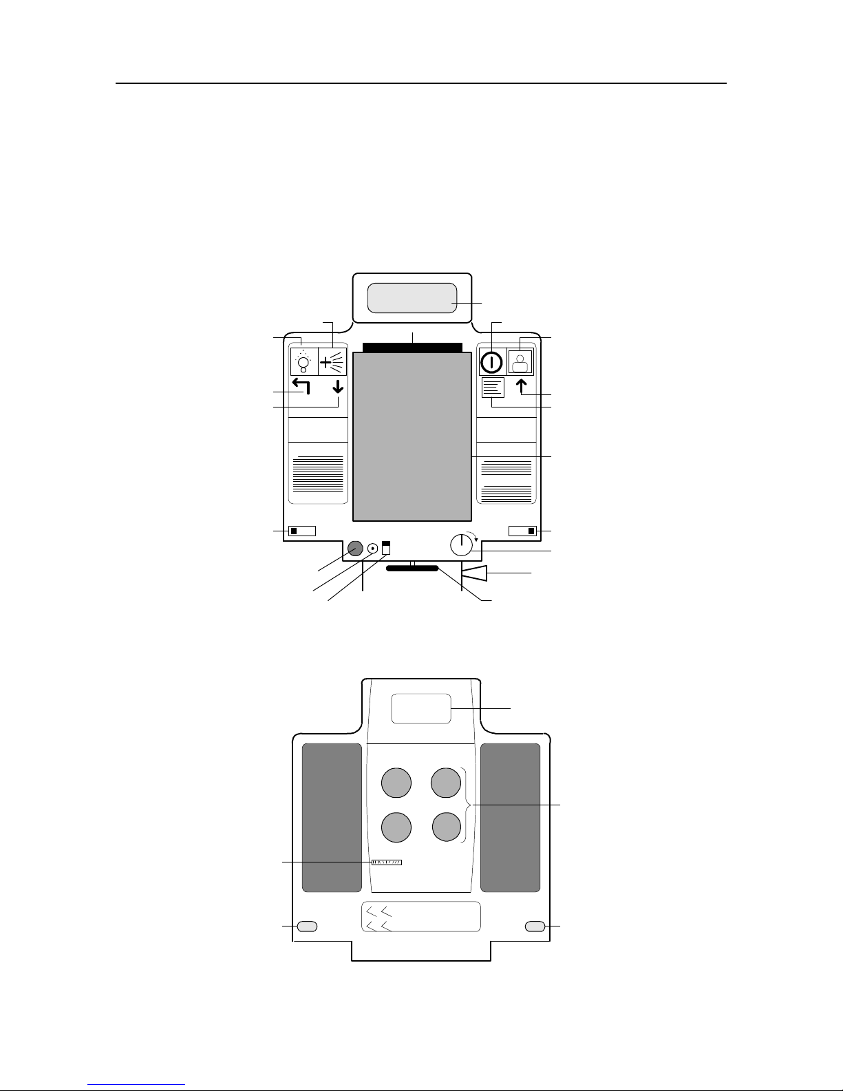
B. Camera Components
Refer to these illustrations as you proceed through the following sections:
Preparing the camera for making ID photos, Making ID photos, and
Programming the camera.
A
P
R
BQ
C
O
N
Polaroid
40 60 4060
G
Caution
Attention
0
I
M
L
K
J
Figure 1-1 Rear (Operational) View
D
E
F
G
H
I
S
V
Polaroid
Figure 1-2 Front View
8
T
UU
Page 9

Repair Manual Model 204/404 MiniPortrait Camera
Rear View Callouts
Call-out Component
A Display Screen
B Program/Power Button
C Shutter Button
D UP Cursor Symbol
E Menu Symbol
F Camera Back
G Aim Light Adjustment Lever
H Camera ON/OFF Switch
I Release Knob
J Locking Knob
K Strobe Switch
L Flash Sync Socket
M Power Cord Socket
N DOWN Cursor Symbol
O EXIT PROGRAM Cursor
Symbol
P Aiming Button
Q Brightener Button
R Dark Slide
Front View Callouts
S Strobe
T Lenses
U Aim Lights
V Aperture Adjustment
9
Page 10

Repair Manual Model 204/404 MiniPortrait Camera
C. Camera Features
Picture version
Totally programmable
Graphic display
Voltages
Battery capability
Low power indicator
Low battery protection
There are two camera versions. The Model 204
makes 2 images per film frame; the Model 404
makes 4 images per film frame. Both use Type
669 film.
Allows operator to program all functions needed
for operation of ID program.
Display guides operator through all
programming and operating functions.
AC/DC adapter operates on 115 or 90 - 250-volt
wall unit.
Operates on 12-volt battery supply.
A low battery icon will appear on the graphic
display and an audio beep will inform the
operator of need to charge or replace battery.
Automatically shuts down if low battery indicator
is ignored, preventing damage to the camera’s
microprocessor.
Variable aperture
Variable exposure
Strobe boost
Strobe count
Pack count
Out of film sensor
Adjustable aperture for different film speeds.
Programmable strobe brightness setting for
exposure in all lighting conditions.
Strobe boost (brightener) button will enhance
brightness by 1/2 stop for one picture without
changing exposure setting.
Counts all strobe flashes. The number will be
displayed in Program Mode; used for tracking
the number of photos produced.
Counts the number of film packs used. Used for
determining/controlling film usage.
Sensor alerts the operator when camera is out
of film.
10
Page 11

Repair Manual Model 204/404 MiniPortrait Camera
Language
Development time
Select capability
Timer
Memory
Auto shut off
Camera display can be programmed to read in
English, Spanish, French, or Italian. Language
can be customized for large volumes.
Development time can be programmed from
thirty (30) seconds to one hundred and ninety
(190) seconds to accommodate all types of film.
Allows the operator to select:
One or two subjects with the 204 camera
One, two or four subjects with 404 camera
Built-in timer will timeout after the film is pulled;
audible beeps signal the operator when the film
is fully developed.
If the camera is turned off during picture-taking,
the existing sequence continues when turned on
again. By not resetting, film waste is prevented.
Camera can be programmed to do the following:
1) Shut off automatically if unused for 10
minutes, or 2) Shut off automatically if unused
for 20 minutes, or 3) Remain on until camera
power is turned off.
Converging lights
viewfinder/rangefinder
Key switch
Tripod mount
Converging flashing light beams allow the
operator to set the proper camera-to-subject
distance, and center the subject in the photo.
Allows power to be turned on or off without
unplugging the camera. Key can be removed to
prevent unauthorized use.
With insert adapter: Standard 1/4-20 screw
mount for desk stand or tripod.
With adapter removed: 3/8-16 screw mount.
11
Page 12

Repair Manual Model 204/404 MiniPortrait Camera
Electronic sync with ON OFF switch
Removable camera back
PC type external X sync connector. Design
allows use of auxiliary flash strobe with option of
turning camera flash strobe ON or OFF.
Dedicated interchangeable camera back (with
removable dark slide).
12
Page 13
Repair Manual Model 204/404 MiniPortrait Camera
D. Operating Instructions
(1) Work area requirements
• Work area of at least 8 x 10 feet; avoid exposure to extreme temperatures
(avoid doors, windows, etc.).
• Table to support camera; 29 - 30 inches (76 cm) high.
• Electrical outlet (ground where applicable).
• Wastebasket.
• Non-reflective (felt or velvet) backdrop to place behind subject; backdrop
should be at least 30 inches (76 cm) square.
• Chair for subject to sit in; should be 17 - 18 inches (45 cm) high.
(2) Preparing the camera for making ID photos
Note: Throughout this section, component names are followed by a letter in parenthesis. This
letter refers to the component location as depicted in Figures 1-1 and 1-2.
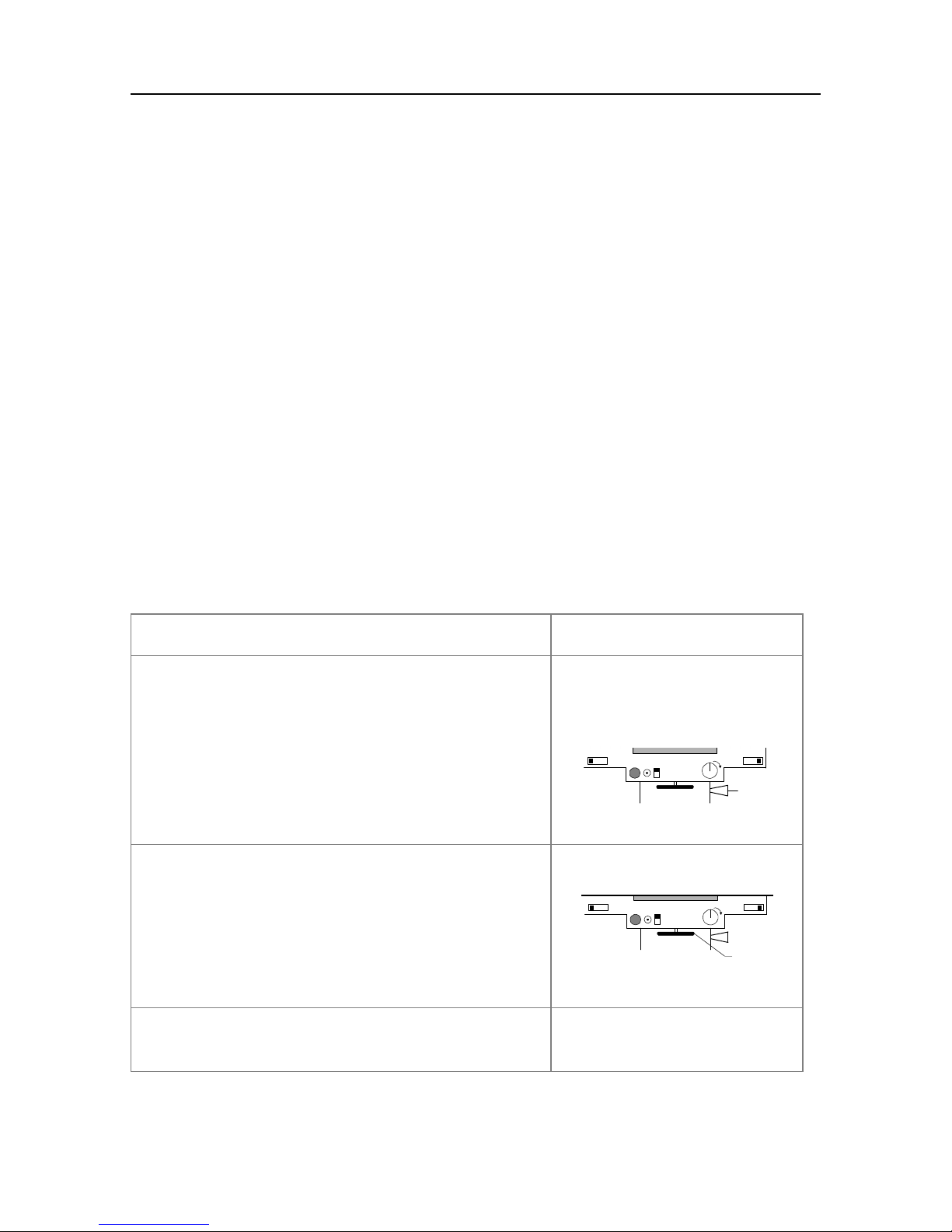
1. Place the camera on the table.
2. Pull out the silver release knob (I) on the
side of the camera base, and while holding it
out, grasp the camera head firmly and swing
it into the upright position. The knob will
click in when the camera is fully upright.
Note: The camera is pivoted to the lower position for
storage and transport.
40 60 4060
0
I
I
3. Tighten the black locking knob (J) under the
camera to prevent it from moving on the
camera base.
Note: If for any reason it is necessary to remove the
camera from the base, unscrew the black knob
completely.
40 60 4060
0
I
J
4. Place the backdrop on the wall and position
a chair in front of the backdrop.
13
Page 14

Repair Manual Model 204/404 MiniPortrait Camera
5. Adjust the camera-to-subject distance.
Place a subject in the chair and measure 40
inches from the camera lenses to the
subject’s chin. This may be approximate
since the final rangefinder adjustment is
made with the aiming lights during picturetaking.
Note: For distances of 60 inches, adjustments can be
made during picture-taking by simply moving the
camera back 20 inches and making final adjustments
with the aiming lights.
6. Plug one end of the AC Adapter into the
power cord socket (M) of the camera and the
other end into the power source. Or, use the
optional 12 volt battery.
40 60 4060
0
I
M
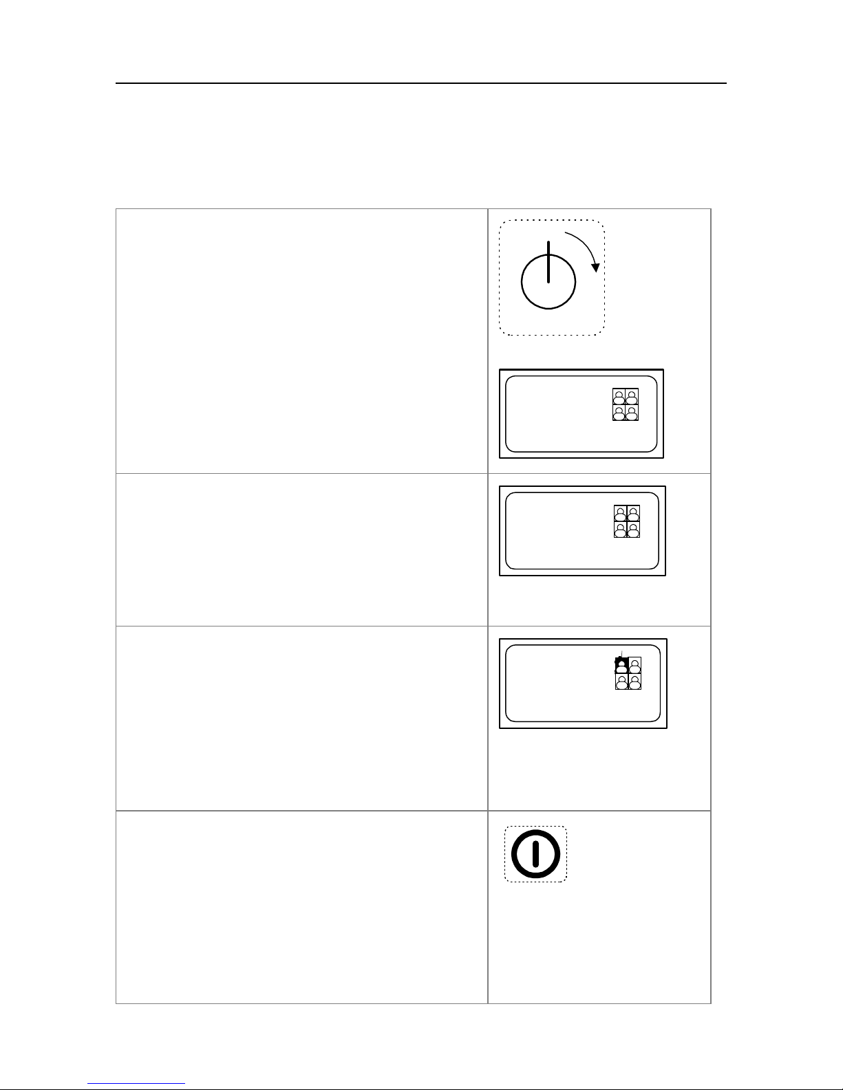
7. Power up the camera by turning the key (H)
clockwise 90° to the ON position (shown by
arrow). Make sure the AC outlet is
grounded.
8. Adjust the aperture (V) for the recommended
f/stop setting. Refer to table at right.
0
I
H
44
64
11
16
22
32
f . . . . . .
Film Speed Aperture
ASA 80 f/11-1/2
ASA 100 f/11-1/2
ASA 125 f/16
ASA 3000 f/64
14
Page 15

Repair Manual Model 204/404 MiniPortrait Camera
9. Set the Aim Light Adjustment Lever (G) for
the proper camera to subject distance; 40
inches for larger image or 60 inches for
smaller image size.
Note: Photos taken at 60 inches require a special
accessory lens.
10. Turn the Strobe Switch (K) to the ON (up)
position.
Note: If using an auxiliary flash, turn the Strobe Switch
to the OFF (down) position; plug the flash into the
Flash Sync Socket (L) of the camera.
11. Remove the camera’s dark slide (R)
40 60 4060
40 60 4060
G
L
K
0
I
0
I
R
GG
15
Page 16
Repair Manual Model 204/404 MiniPortrait Camera
(3) Making ID photos
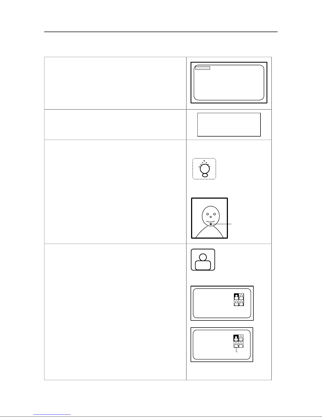
1. Power up the camera by turning the key (H)
clockwise 90° (as shown by arrow).
A LOAD FILM message appears in the
Display Screen (A).
2. Load the film into the Camera Back (F).
A PULL FILM message appears in the
Display Screen. Also, a “1” (indicating first
film frame) is visible in the upper left corner.
Note: If a partially used film pack is inserted, a
READY message is displayed.
0
I
H
LOAD FILM
1
PULL FILM
3. Pull the film safety cover; a white tab will be
visible.
A READY message appears in the Display
Screen and the first image blinks.
Note: The imaging format for each frame depends on
the PICTURE SELECT menu explained in the next
section. For example, four different images, four
identical images, or, two double images.
4. Prior to taking ID photos, access the
Program Mode to make appropriate camera
adjustments. Begin by pressing the
Program/Power Button (B).
16
1
READY
Blinking
B
Page 17
Repair Manual Model 204/404 MiniPortrait Camera
4. Continued
COUNTS
The program menu (at right) will appear.
Note: For details about each adjustment screen, refer
to the next section, “Programming the camera”.
EXPOSURE FILM
PICTURE SELECT 000380
DEVELOPMENT TIME
RESET COUNTS STROBE
LANGUAGE 001139
AUTO SHUT OFF
EXIT
5. Check to make sure the camera aperture is
set according to the film type being used.
6. Aim the camera as follows:
Press the Aiming Button (P) and the Aiming
Light will come on; it will blink for
approximately 15 seconds. Center the
converging light spots on the subject’s chin
for proper framing.
Note: Once the Aiming Light goes out, the Shutter
Button is deactivated and a picture cannot be taken
until the Aiming Light Button is pressed again.
7. Press the Shutter Button (C) to take the
picture.
Film Film Speed Aperture
T669 ASA 80 f/11 1/2
T100 ASA 100 f/11 1/2
T667 ASA 3000 f/64
P
Converging light
beams
While the strobe is recharging, a WAIT
message is displayed.
A READY message informs the operator that
the second picture on the frame can now be
taken. Also, the next image blinks.
17
C
1
WAIT
1
READY
Blinking
Page 18
Repair Manual Model 204/404 MiniPortrait Camera
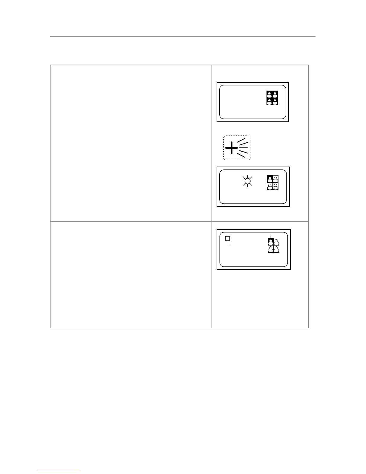
7. Continued
Continue taking pictures until each photo on
the frame is taken.
When all photos are taken, a PULL FILM
message appears and all four image boxes
are solid.
Note: If the subject has a dark complexion, more
illumination can be provided by pressing the
Brightener Button (Q) just prior to taking the photo. It
is activated for one photo only.
A starburst (shown at right) informs the operator that
the Image Brightener is activated for that photo.
8. Pull the film from the camera; first the white
tab, then the yellow tab. A READY message
is displayed. Also, a “2” (indicating the
second frame about to be taken) appears in
the upper left corner.
1
PULL FILM
1
1 2
Blinking
Q
READY
Blinking
READY
Lay the picture frame on a flat surface while
developing. Audible beeps will signal when
development is complete.
After development, separate the print from
the negative.
18
Page 19

Repair Manual Model 204/404 MiniPortrait Camera
(4) Programming the camera
This section describes the process for accessing the Program Mode and making
the required adjustments prior to picture-taking.
Important: The Display Screen must read READY or LOAD FILM in order to access the Program
Mode (refer to item 4. in the previous section, “Making ID photos”).
1. Press the Program/Power Button (B)...
B
... and the program menu (at right) will be
displayed. This initial screen highlights
COUNTS, which shows the number of film
frames that have been pulled, and the
number of strobe firings. No adjustments are
made in this screen.
Note: You can scroll and select any item on the menu
by pressing and holding the Program/Power Button;
the selection will be made upon releasing the button.
2. Press the Program/Power Button (B) a
second time and the EXPOSURE adjustment
screen is displayed. A range of seven
exposure settings can be selected.
To decrease exposure, repeatedly press the
Brightener Button (Q) until the desired
exposure is set. When in the Program
Mode, this button acts as a DOWN cursor
(indicated by arrow).
COUNTS
EXPOSURE FILM
PICTURE SELECT 000380
DEVELOPMENT TIME
RESET COUNTS STROBE
LANGUAGE 001139
AUTO SHUT OFF
EXIT
EXPOSURE
Q
19
Page 20

Repair Manual Model 204/404 MiniPortrait Camera
2. Continued
To increase exposure, press the Shutter
Button (C) until the desired exposure is set.
This button acts as an UP cursor (indicated
by the arrow).
3. Press the Program/Power Button (B) a third
time to enter the PICTURE SELECT screen.
Use either the UP or DOWN cursor [Shutter
Button (C) or Brightener Button (Q)] to make
selections described in the following
sequence.
When the upper left box is selected, one
individual photo will be taken each time the
Shutter Button is pressed. With this
selection, the Shutter Button is pressed four
times per film frame.
C
PICTURE SELECT
C Q
PICTURE SELECT
When two vertical boxes are selected, two
identical photos (2-up) will be taken each
time the Shutter Button is pressed. With this
selection, the Shutter Button is pressed twice
per film frame.
When all four boxes are selected, four
identical photos will be taken each time the
Shutter Button is pressed. With this
selection, the Shutter Button is pressed once
per film frame.
PICTURE SELECT
PICTURE SELECT
20
Page 21

Repair Manual Model 204/404 MiniPortrait Camera
4. Press the Program/Power Button (B) a fourth
time to enter the DEVELOPMENT TIME
screen. Setting development time
determines how long the film will develop
before the timer beeps.
Development time is set (as described
below). The selected time, accompanied by
a black band, will be shown on the screen
(60 seconds in the example at right).
To increase development time, press the UP
cursor [Shutter Button (C)].
To decrease development time, press the
DOWN cursor [Brightener Button (Q)].
DEVELOPMENT TIME
C
190
60
30
5. Press the Program/Power Button (B) a fifth
time to enter the RESET COUNTS screen.
Use either the UP or DOWN cursor [Shutter
Button (C) or Brightener Button (Q)] to reset
the counts (reset to 0).
Q
FILM
000381
RESET COUNTS STROBE
001140
C Q
21
Page 22

Repair Manual Model 204/404 MiniPortrait Camera
6. Press the Program/Power Button a sixth time
to enter the LANGUAGE screen.
LANGUAGE
ENGLISH
ESPANOL
FRANCAIS
ITALIAN
Use either the UP or DOWN cursor [Shutter
Button (C) or Brightener Button (Q)] to select
the language you want to display in the
screen text.
C Q
7. Press the Program/Power Button a seventh
time to enter the AUTO SHUT OFF screen.
This programs the camera to automatically
shut off after sitting idle for the selected
amount of time. If set to 10 MIN, the camera
AUTO SHUT OFF
OFF
10 MIN
20 MIN
will automatically shut down if unused for 10
minutes; if set to 20 MIN, it will shut down
after 20 minutes. If set to OFF, AUTO SHUT
OFF is disabled and the camera will remain
on until the key is turned off.
Use either the UP or DOWN cursor [Shutter
Button (C) or Brightener Button (Q)] to make
the selection.
8. Press the Program/Power Button an eighth
time to exit the program. The READY (or
LOAD FILM) screen will be displayed; the
operator can resume picture-taking.
To exit the Program Mode at any time from
any of the earlier screens, select EXIT from
the menu. Or, press the Aiming Button (P) to
escape.
C Q
READY
COUNTS
EXPOSURE FILM
PICTURE SELECT 000380
DEVELOPMENT TIME
RESET COUNTS STROBE
LANGUAGE 001139
AUTO SHUT OFF
EXIT
P
22
Page 23

Repair Manual Model 204/404 MiniPortrait Camera
Section 2. Troubleshooting
A. Camera Diagnostics .......................................................................................24
(1) Accessing and using the diagnostics.......................................................24
(2) Performing the required tests...................................................................25
B. Troubleshooting Charts..................................................................................27
(1) Picture quality problems...........................................................................27
(2) LCD display problems..............................................................................30
(3) Miscellaneous camera problems..............................................................33
23
Page 24

Repair Manual Model 204/404 MiniPortrait Camera
A. Camera Diagnostics
Functional checks can be made by using the camera’s built-in diagnostic
capability. Below is the procedure for (1) Accessing and using the diagnostics
and (2) Performing the required tests.
(1) Accessing and using the diagnostics
To enter the camera’s Diagnostics
Mode, first place tape over the Pull
Film Switch (to hold it in) and the Load
Film Sensor - masking tape will do.
Next, press the Shutter Button (C), and
while keeping it depressed, push the
Program/Power button (B).
C B
The diagnostics menu will appear in
the LCD panel.
Each of these tests is described in (2)
Performing the required tests.
To scroll down the menu, press the
Brightener Button (Q) which performs a
scrolling function when in the
Diagnostic Mode.
To scroll up the menu, press the
Shutter Button (C) which performs a
scrolling function when in the
Diagnostic Mode.
After selecting a menu item, press the
Program/Power Button to activate the
test (B).
Run In Display
Aim Lamp Strobe
Beeper Exit
Shutters
000000 Strobe Version P36
000000 Watchdog
(Q)
(C)
(B)
24
Page 25

Repair Manual Model 204/404 MiniPortrait Camera
To exit the Diagnostic Mode at any
time, press the Aiming Button (P) which
performs the exit function when in the
Diagnostic Mode. Or, select Exit from
the menu.
(2) Performing the required tests
Test: Function performed:
Run In Simulates normal camera operation - LCD panel
displays RUN-IN WITH COUNTER, shutters open
and close, and strobe fires (at both nominal and
maximum intensity). This continues until test mode
reaches 200 firings. Identifies the following:
LCD panel not illuminated, not readable, etc.
Shutters not functioning properly.
Strobe not firing or firing intermittently.
Aim Lamp Aim Lamp blinks for one minute. This test can be
reactivated after a five minute cool-down period.
Identifies the following:
Aiming light not coming on, or not remaining on.
Aiming light not blinking.
Beeper Timer beeps continuously until test mode is exited.
Identifies the following:
Development timer not beeping at completion of
film development.
Shutters Sequentially opens and closes each shutter. This
continues until test mode is exited. Identifies the
following:
Shutter malfunctioning; not opening or closing,
sticking, etc.
25
Page 26

Repair Manual Model 204/404 MiniPortrait Camera
Test: Function performed:
Display Display area flashes back and forth between blue
and white. Remains illuminated until test mode is
exited. Ideally, the blue area should be smooth in
texture. Identifies the following:
Missing pixels. Uneven blue density areas
indicate missing pixels which may affect
readability in the display area.
Strobe Strobe fires continuously until test mode is exited.
Identifies the following:
Strobe not firing or firing intermittently.
Insufficient (or low) strobe output.
Exit Select Exit to leave the Diagnostic Mode.
Version Current software version.
Strobe Counter Displays the number of times the strobe has been
fired.
Watchdog Counter Displays the number of times the watchdog system
has been activated, indicating possible processor
problem.
26
Page 27

Repair Manual Model 204/404 MiniPortrait Camera
B. Troubleshooting Charts
(1) Picture quality problems
Problem Cause Corrective action
Repeated, evenlyspaced spots.
Missing corners, or
orange-red marks along
edges.
Rectangular outline in
print.
Small white specks, pink
lines, streaks or blotches.
Dirty developer rollers. Clean developer rollers.
Pulling the film tab from
the camera at an angle.
Pull the yellow/black film
tab straight from the
camera.
Dried developer on the
Clean developer rollers.
rollers.
White leader tab not
pulled completely off
prior to pulling the film
tab; white tab passes
Pull white tab completely
out of camera before
pulling the film from the
camera.
through the rollers with
the film.
Pulling the film through
the rollers too fast.
Pull the film using a
smooth, even moderate
pull speed.
Muddy-looking print. Development time not
Broad streak or mark
across the picture.
long enough.
Hesitating while pulling
the film from the camera.
27
Develop film for time
recommended in film
instruction sheet.
Pull the film tab straight
out in one motion,
without hesitation.
Page 28

Repair Manual Model 204/404 MiniPortrait Camera
Problem Cause Corrective action
Picture too light. Film fogged.
Incorrect aperture
setting.
Picture too dark. Incorrect aperture
setting.
Do not remove the safety
cover prior to loading the
film. Also, do not open
the camera and dislodge
the film pack during
picture-taking.
Reset aperture to higher
number (reduces
aperture size allowing
less light to reach
negative).
Note: Exposure
correction can also be
made in Program Mode
Reset aperture to lower
number (increases
aperture size allowing
more light to reach
negative).
Flash didn’t fire.
Picture completely white. Fogged film.
Defective shutter (Sticks
open).
Note: Exposure
correction can also be
made in Program Mode
Refer to “flash didn’t fire”
(Page 38).
Replace film.
Replace shutter
assembly.
28
Page 29

Repair Manual Model 204/404 MiniPortrait Camera
Problem Cause Corrective action
Picture completely black. No exposure; dark slide
not pulled out before
taking picture.
Flash not firing.
Defective shutter (not
opening).
Image size too large or
too small in picture area;
possible out-of-focus
(blurry) image.
Inaccurate camera-tosubject distance, caused
by any one of the
following:
1) Camera too close or
too far from subject; two
separate aiming lights
beams appear on
subject’s chin.
Remove film holder’s
dark slide before taking
picture.
Refer to “Flash didn’t
fire” (Page 38).
Replace shutter
assembly.
Adjust camera-to-subject
distance until the two
aiming lights converge
into one beam on
subject’s chin.
2) Aiming light switch on
wrong setting; subject
positioned 40 inches
from camera and switch
set for 60. Or, subject
positioned 60 inches and
switch set at 40 inches.
Two separate light
beams appear on
subject’s chin.
3) Aiming lights out of
adjustment.
Set aiming light switch
according to actual
camera-to-subject
distance.
Aiming light must be
factory adjusted.
29
Page 30

Repair Manual Model 204/404 MiniPortrait Camera
Problem Cause Corrective action
Subject blurry; image
size accurate.
Not using accessory lens
when taking pictures at
distance of 60 inches
from subject.
Dirty lens.
Use accessory closeup
lens when camera-to-
subject distance is 60
inches.
Clean lens with lens
tissue; or use eyeglass
cleaning tissue as
substitute.
Improperly seated
Recheck lens seating.
accessory closeup lens.
(2) LCD display problems
Problem Cause Corrective action
No image in LCD display
screen.
Check all connections. If
broken or disconnected,
take corrective action. If
not, see below.
Reconnect or replace as
needed. 20-pin harness
from LCD to logic board;
or 10-pin parallel
harness between power
board and logic board.
System not plugged in. If
not, take corrective
action. If yes, see below.
Check to make sure the
system is turned on. If
there is still no image,
see below.
30
Plug one end of AC
adapter into power cord
socket of camera and the
other end into power
source.
Power up the camera by
turning the key
clockwise.
Page 31

Repair Manual Model 204/404 MiniPortrait Camera
Continued
No image in LCD display
screen.
System may have shut
down after preset time
while in auto mode. If
yes, take corrective
action. If not, see below.
Check the battery; or AC
adapter (whichever is
being used). If battery is
dead or AC adapter is
defective, take corrective
action. If not, see below.
Check to see if 5 volts is
coming off the power
board. If not, take
corrective action. If yes,
see below.
Logic board is defective.
Take corrective action. If
still no image, see below.
Press program mode
button to re-activate
system.
Replace battery, or AC
adapter.
Replace power board.
Replace logic board.
No LOAD FILM message
(either no message or
wrong message) when
camera is out of film.
LOAD FILM message
stays on at all times,
even when camera has
film.
No PULL FILM message
in LCD display after
loading film.
PULL FILM message
stays on at all times;
even after film is pulled.
LCD display has failed.
Defective load film
sensor unit; not sensing
film in film compartment,
broken wire(s), or dirty
sensor unit.
Load Film/Pull Film
harness not plugged into
J3 on the logic board.
Load Film/Pull Film
harness not plugged into
J3 on the logic board.
Pull film switch sticking in
closed position. If yes,
take corrective action. If
not, see below.
Replace LCD display.
Replace load film sensor
unit; or wire(s) as
necessary. Or, clean
sensor unit if needed.
Plug harness into J3 on
the logic board.
Plug harness into J3 on
the logic board.
Clean pull film switch.
31
Page 32

Repair Manual Model 204/404 MiniPortrait Camera
Continued
PULL FILM message
stays on at all times;
even after film is pulled.
Film in camera, READY
is displayed, but nothing
happens when shutter
button is pressed.
Pull film switch out of
adjustment. If yes, take
corrective action. If not,
see below.
Faulty pull film switch.
Operator attempted to
take picture after aiming
light went out. Or, aiming
light doesn’t come on for
the reasons described in
(1.) and (2.)below.
(1.) Aiming light bulb
burnt out.
(2.) Aiming light switch
failed; not closing when
aiming button is pressed.
Adjust pull film switch.
Replace pull film switch.
Press aiming light button
again and take picture
before aiming light goes
out.
Replace bulb.
Replace aiming light
switch.
Unable to access
Program Mode; menu
doesn’t appear when
Program Mode button is
pressed.
PULL FILM message
appears when operator
attempts to change
Picture Select menu in
Program Mode
Defective shutter switch;
not closing when pushed
in.
PULL FILM displayed in
LCD panel. When in
PULL FILM mode,
Program Mode cannot be
accessed.
Operator attempted to
change Picture Select
menu prior to taking all
photos on the frame.
Replace shutter switch.
Pull the film frame.
When display reads
READY, Program Mode
can be accessed.
If it’s necessary to
change the Picture
Select menu before all
photos on the frame are
used up, first pull the
film. When READY is
displayed, the menu can
be changed.
32
Page 33

Repair Manual Model 204/404 MiniPortrait Camera
(3) Miscellaneous camera problems
Problem Cause Corrective action
Flash didn’t fire. Strobe switch not turned
ON.
Defective strobe
assembly.
Strobe connector not
plugged into power
board.
Defective strobe circuit.
Auxiliary flash not
plugged into flash sync
socket (when using
auxiliary flash only).
Aiming lights don’t
illuminate.
Aiming light bulb is
burned out.
Aiming light bulb board is
defective.
Turn strobe switch ON.
Replace strobe
assembly.
Plug strobe connector
into J1 on power board.
Replace power board.
Plug auxiliary flash into
flash sync socket and
turn camera’s strobe
switch OFF.
Replace aiming light
bulb/board.
Same as above.
Aiming light connector
not plugged in.
33
Plug in aiming light
connector to J5 on logic
board.
Page 34

Repair Manual Model 204/404 MiniPortrait Camera
Section 3. Parts replacement
Required Tools...................................................................................................... 35
A. Removing the Front and Rear Housing............................................................ 36
B. Replacing the Aiming Light...............................................................................38
C. Replacing the Strobe Assembly ....................................................................... 41
D. Replacing the shutter assembly .......................................................................42
E. Replacing the shutter solenoid(s).................................................................... 43
F. Replacing the Pull Film Switch ......................................................................... 46
G. Replacing the Load Film Sensor......................................................................49
H. Replacing the Logic Board............................................................................... 51
I. Replacing the Power Board .............................................................................53
J. Replacing the LCD Display Board..................................................................... 55
K. Replacing the Capacitor................................................................................... 56
34
Page 35

Repair Manual Model 204/404 MiniPortrait Camera
Required Tools
Below is a list of tools and test equipment needed for disassembly, reassembly
and adjustment of the MiniPortrait 204/404 camera.
• Phillips head screwdriver (Point size 0, 1, 2)
• Needlenose pliers (straight and curved)
• Tweezers
• Small wire cutters
• Soldering iron
• Greenstick (solder aid tool) #941168
• Allen wrench set
• Wrist strap and grounded anti-static mat
• Finger cots/lintless gloves
• Black RTV sealant
• Dump probe #13119
• Pull film switch Go/No-Go gauge #AD-90
35
Page 36

Repair Manual Model 204/404 MiniPortrait Camera
pan head
pan head
pan head
A. Removing the Front and Rear Housing
1. Turn the system off.
2. Unlatch and remove the Camera Back (Figure 3-1) from the rear housing.
3. Remove the seven (7) phillips screws from the Rear Housing. There are
three (3) screws on each side (#6 x 5/8” phillips pan head) and one (1) in the
bottom center of the housing (#6 x 1/2” phillips black pan head). (Figure 3-1)
4. Gently separate the Front and Rear Housings enough to access the electrical
connectors.
5. Unplug the aiming light connector from J5 on the Logic Board. (Figure 3-2)
6. Unplug the strobe connector from J1 on the Power Board. (Figure 3-2)
7. Unplug the capacitor connectors from J3 on the Power Board. (Figure 3-2)
8. The Front and Rear Housings can now be fully separated so that internal
subassemblies can be repaired or replaced as necessary.
9. Reverse steps one (1) through seven (7) above to reassemble the housings.
#6 x 5/8” phillips
#6 x 5/8” phillips
Camera
back
phillips pan head
phillips pan head
#6 x 5/8”
#6 x 5/8”
#6 x 1/2” phillips
pan head black
#6 x 5/8” phillips
#6 x 5/8”
phillips pan head
Figure 3-1 Removing the Front/Rear Housing
36
Page 37

Repair Manual Model 204/404 MiniPortrait Camera
Power board
Strobe connector
to J1
Capacitor
Aiming lights
Viewfinder
connector to J5
Capacitor
connector
to J3
Figure 3-2 Unplugging the Electrical Connections
LCD Display
board
Logic board
37
Page 38

Repair Manual Model 204/404 MiniPortrait Camera
B. Replacing the Aiming Light
Note: If one Aiming Light bulb burns out always check the other because they are in
series.
1. Turn the system off.
2. Unlatch and remove the Camera Back (Figure 3-1) from the rear housing.
3. Remove the seven (7) phillips screws from the Rear Housing. There are
three (3) screws on each side (#6 x 5/8” phillips pan head) and one (1) in the
bottom center of the housing (#6 x 1/2” phillips black pan head). (Figure 3-1)
4. Gently separate the Front and Rear Housings enough to access the electrical
connectors.
5. Unplug the following connectors: (a) aiming light connector from J5 on the
Logic Board; (b) strobe connector from J1 on the Power Board; and (c)
capacitor connector from J3 on the Power Board. (Figure 3-2)
6. Separate the Front and Rear Housings for access to the Aiming Lights.
7. Unplug the Aiming Light connector. (Figure 3-3)
8. Remove the two (2) #6 x 1/4” phillips screws securing the Bulb/board to the
Tube Assembly. (Figure 3-3) Note that when a bulb malfunctions, the entire
board (containing bulb) must be replaced.
9. Install a replacement Bulb/board.
10. Reassemble the camera by reversing steps one (1) through eight (8).
Aim Light Adjustment
Check the vertical alignment of the aiming lights as follows:
1. With the system on, face the camera toward a wall at a distance of 40 inches.
2. Set the camera’s aiming switches to 40 inches.
3. Place a target, consisting of two intersecting lines, on the wall.
38
Page 39

Repair Manual Model 204/404 MiniPortrait Camera
4. Press the aiming button and move the camera away from the target until the
converging light beams are aligned on the target. In the illustration below,
both beams are properly aligned on the horizontal axis.
4A
However, if one light is higher than the other, as shown below, it must be
adjusted downward.
4B
Lower the Aiming Light as follows: (Refer to Figure 3-4)
a) Access “Aim Lamp” in the diagnostic menu as described in Section 2 of
this manual. The Aiming Light will blink for one (1) minute so that it can be
checked and adjusted if necessary.
b) Insert a 1/32 inch allen wrench into the Aiming Light adjustment opening
in the Rear Housing (Figure 3-4). Note: There are two adjustment
openings, one for the left Aiming Light and one for the right Aiming Light.
c) Turn the adjustment screw clockwise until the beam is lowered into
vertical alignment with the lower beam as shown in number 4A above. At
40 inches, the beams will be superimposed for proper framing on the
subject’s chin.
39
Page 40

Repair Manual Model 204/404 MiniPortrait Camera
Tube
assembly
Aiming light
connector
Bulb board
Figure 3-3 Replacing the Aiming Light
Aiming light
adjustment
screw
Figure 3-4 Adjusting the Aiming Light
40
Page 41

Repair Manual Model 204/404 MiniPortrait Camera
C. Replacing the Strobe Assembly
1. Turn the system off.
2. Unlatch and remove the Camera Back (Figure 3-1) from the rear housing.
3. Remove the seven (7) phillips screws from the Rear Housing. There are
three (3) screws on each side (#6 x 5/8” phillips pan head) and one (1) in the
bottom center of the housing (#6 x 1/2” phillips black pan head). (Figure 3-1)
4. Gently separate the Front and Rear Housings enough to access the electrical
connectors.
5. Unplug the following connectors: (a) aiming light connector from J5 on the
Logic Board; (b) strobe connector from J1 on the Power Board; and (c)
capacitor connector from J3 on the Power Board. (Figure 3-2)
6. Separate the Front and Rear housings for access to the Strobe Assembly.
(Figure 3-1)
7. Remove the two (2) #4 x 3/8” phillips screws securing the Strobe Assembly
(consisting of Strobe Board, Reflector and Flash Tube) to the housing.
(Figure 3-5)
8. Install a replacement Strobe Assembly.
9. Reassemble the camera by reversing steps one (1) through seven (7).
Strobe
assembly
#4 x 3/8”
phillips (2)
Strobe
connector
Figure 3-5 Replacing the Strobe Assembly
41
Page 42

Repair Manual Model 204/404 MiniPortrait Camera
D. Replacing the Shutter Assembly
1. Turn the system off.
2. Unlatch and remove the Camera Back (Figure 3-1) from the rear housing.
3. Remove the seven (7) phillips screws from the Rear Housing. There are
three (3) screws on each side (#6 x 5/8” phillips pan head) and one (1) in the
bottom center of the housing (#6 x 1/2” phillips black pan head). (Figure 3-1)
4. Gently separate the Front and Rear Housings enough to access the electrical
connectors.
5. Unplug the following connectors: (a) aiming light connector from J5 on the
Logic Board; (b) strobe connector from J1 on the Power Board; and (c)
capacitor connector from J3 on the Power Board. (Figure 3-2)
6. Separate the Front and Rear Housings for access to the Shutter Assembly.
7. From inside the housing, unplug the shutter connector from J7 on the Logic
Board. (Figure 3-13)
8. Remove the Shutter Assembly by removing the four (4) #6 x 1/4” black
phillips screws from inside the Baffle. (Figure 3-6)
9. Lift out the Shutter Assembly.
10. Install the replacement Shutter Assembly.
11. Reassemble the camera by reversing steps one (1) through eight (8).
#6 x1/4” black
phillips (4)
Baffle
assembly
Shutter
assembly
Figure 3-6 Removing the Shutter Assembly
42
Page 43

Repair Manual Model 204/404 MiniPortrait Camera
E. Replacing the Shutter Solenoid(s)
Note: Solenoids can be replaced individually, it is not necessary to replace the entire
harness and four (4) solenoids if one is defective.
1. Turn the system off.
2. Unlatch and remove the Camera Back (Figure 3-1) from the rear housing.
3. Remove the seven (7) phillips screws from the Rear Housing. There are
three (3) screws on each side (#6 x 5/8” phillips pan head) and one (1) in the
bottom center of the housing (#6 x 1/2” phillips black pan head). (Figure 3-1)
4. Gently separate the Front and Rear Housings enough to access the electrical
connectors.
5. Unplug the following connectors: (a) aiming light connector from J5 on the
Logic Board; (b) strobe connector from J1 on the Power Board; and (c)
capacitor connector from J3 on the Power Board. (Figure 3-2)
6. Separate the Front and Rear Housings for access to the Shutter Assembly.
7. From inside the housing, unplug the shutter connector from J7 on the Logic
Board. (Figure 3-13)
8. Remove the Shutter Assembly by removing the four (4) #6 x 1/4” black
phillips screws from inside the Baffle. (Figure 3-6)
9. Disassemble the Shutter Assembly as follows:
a) Remove the two (2) #4 x 1/4” phillips pan head screws from the Aperture
Cover. Lift off the Aperture Cover. (Figure 3-7)
b) Lift out the Actuating Arm, Aperture Lever and Aperture Plates.
(Figure 3-7)
c) Remove the four (4) #6 x 1/2” phillips flat head screws from each corner of
the Shutter Plate. (Figure 3-7)
d) Remove the two (2) #2-56 x 1/8” phillips black pan head screws securing
the Solenoid to the Shutter Plate. Lift the Solenoid from the underside of
the plate (Figure 3-8). During reassembly, note how the Solenoid pin
engages the Shutter Blade.
e) Cut the tie wrap and pull the solenoid wires from the connector; two wires
with each Solenoid. (Figure 3-8)
Important: Note the location of the removed solenoid wires during disassembly.
Replacement solenoid wires must be inserted into the same pin number slots of
the connector during reassembly. Push wires down into the slots using a small
flathead screwdriver.
43
Page 44

Repair Manual Model 204/404 MiniPortrait Camera
f) Install the replacement Solenoid by reversing steps a) through e)”.
Important: Since both plates are identical, make sure they are properly oriented
(Figure 3-7); top plate with teardrop to the left and bottom plate with teardrop to
the right.
10. Reassemble the camera by reversing steps one (1) through eight (8).
Shutter plate
#6 x 1/2” phillips flat head (4)
Aperture plates (2)
Actuating arm
Aperture lever
#2-56 x 1/8”
phillips black
pan head (2/ solenoid)
Aperture
cover
#4 x 1/4” phillips
pan head (2)
Figure 3-7 Replacing the Solenoid(s)
44
Page 45

Repair Manual Model 204/404 MiniPortrait Camera
Connector
#2-56 x 1/8”
phillips black
pan head (2)
Shutter
Solenoid Shutter blade
plate
(underside)
Figure 3-8 Solenoid/Shutter Blade Orientation on Underside of Shutter Plate
45
Page 46

Repair Manual Model 204/404 MiniPortrait Camera
F. Replacing the Pull Film Switch
1. Turn the system off.
2. Unlatch and remove the Camera Back (Figure 3-1) from the rear housing.
3. Remove the seven (7) phillips screws from the Rear Housing. There are
three (3) screws on each side (#6 x 5/8” phillips pan head) and one (1) in the
bottom center of the housing (#6 x 1/2” phillips black pan head). (Figure 3-1)
4. Gently separate the Front and Rear Housings enough to access the electrical
connectors.
5. Unplug the following connectors: (a) aiming light connector from J5 on the
Logic Board; (b) strobe connector from J1 on the Power Board; and (c)
capacitor connector from J3 on the Power Board. (Figure 3-2)
6. Separate the Front and Rear Housings for access to the Shutter Assembly.
7. From inside the housing, unplug the shutter connector from J7 on the Logic
Board. (Figure 3-13)
8. Remove the Shutter Assembly by removing the four (4) #6 x 1/4” black
phillips screws from inside the Baffle. (Figure 3-6)
9. Unplug the load film/pull film harness connector from J3 on the Logic Board.
(Figure 3-13)
10. Remove the Baffle from the rear housing assembly by removing the four (4)
#6 x 1/2” black pan head phillips screws located inside the Rear Housing.
(Figure 3-9)
11. Remove the two (2) #2-56 x 7/16” black phillips pan head bolts (and #2 tooth
lock washer/#2-56 hex nut) securing the Pull Film Switch to the Baffle.
Remove the switch. (Figure 3-10)
12. Install the replacement Pull Film Switch. Be careful not to overtighten the two
(2) phillips bolts/nuts. (Figure 3-10)
13. Attach the Baffle to the Rear Housing assembly by securing the four (4) #6 x
1/2” black pan head phillips screws. (Figure 3-9)
14. Attach the Camera Back to the Baffle.
15. Check the height adjustment of the Pull Film Plunger (in the Camera Back)
using the go/no-go gauge (tool AD-90). (Figure 3-11)
The switch should “click ON” when the low end (go) of the gauge is placed
over the Pull Film Plunger (located in the camera back). It should not “click
ON” when the high end (no-go) of the gauge is placed over the Plunger.
Adjust as needed, using the two (2) screws which mount the Pull Film Switch.
46
Page 47

Repair Manual Model 204/404 MiniPortrait Camera
Important: Once adjusted, place dab of glue (the size of a pin head) on the corner of
the Switch Assembly. Just enough to prevent it from shifting, but not enough to make
it impossible for future removal. To remove a glued switch, gently twist the assembly
with pliers until the bond breaks.
16. Reassemble the camera by reversing steps one (1) through nine (9).
Baffle
#6 x 1/2” black
phillips pan
head (4)
Figure 3-9 Removing the Baffle
Baffle
Rear
housing
# 2 lock washer (2)
and #2-56 hex nut (2)
Pull film
switch
# 2-56 x 7/16”
phillips pan
head (2)
Figure 3-10 Removing the Pull Film Switch
47
Page 48

Repair Manual Model 204/404 MiniPortrait Camera
Go/no-go gauge
(tool AD-90)
Pull film plunger
Figure 3-11 Checking Switch Function with Go/No-Go Gauge
48
Page 49

Repair Manual Model 204/404 MiniPortrait Camera
G. Replacing the Load Film Sensor
1. Turn the system off.
2. Unlatch and remove the Camera Back (Figure 3-1) from the rear housing.
3. Remove the seven (7) phillips screws from the Rear Housing. There are
three (3) screws on each side (#6 x 5/8” phillips pan head) and one (1) in the
bottom center of the housing (#6 x 1/2” phillips black pan head). (Figure 3-1)
4. Gently separate the Front and Rear Housings enough to access the electrical
connectors.
5. Unplug the following connectors: (a) aiming light connector from J5 on the
Logic Board; (b) strobe connector from J1 on the Power Board; and (c)
capacitor connector from J3 on the Power Board. (Figure 3-2)
6. Separate the Front and Rear Housings for access to the Shutter Assembly.
7. From inside the housing, unplug the shutter connector from J7 on the Logic
Board. (Figure 3-13)
8. Remove the Shutter Assembly by removing the four (4) #6 x 1/4” black
phillips screws from inside the Baffle. (Figure 3-6)
9. Unplug the load film/pull film harness connector from J3 on the Logic Board.
(Figure 3-13)
10. Remove the Baffle from the rear housing assembly by removing the four (4)
#6 x 1/2” black pan head phillips screws located inside the Rear Housing.
(Figure 3-9)
11. Remove the Load Film Sensor Board by removing the two (2) #4 x 3/8”
phillips pan head screws. (Figure 3-12)
12. Slide the Load Film Sensor out of the Baffle Frame as shown in Figure 3-12.
13. Install the replacement Load Film Sensor and secure the Sensor Board with
the two (2) #4 x 3/8” phillips pan head screws.
14. Attach the Baffle to the Rear Housing Assembly by securing the four (4) #6 x
1/2” black pan head phillips screws. (Figure 3-9)
15. Reassemble the camera by reversing steps one (1) through nine (9).
49
Page 50

Repair Manual Model 204/404 MiniPortrait Camera
Baffle
Load film
sensor board
Sensors (2)
#4 x 3/8”
phillips pan head
Mounting
spacer
Figure 3-12 Replacing the Load Film Sensor
50
Page 51

Repair Manual Model 204/404 MiniPortrait Camera
H. Replacing the Logic Board
1. Turn the system off.
2. Unlatch and remove the Camera Back (Figure 3-1) from the rear housing.
3. Remove the seven (7) phillips screws from the Rear Housing. There are
three (3) screws on each side (#6 x 5/8” phillips pan head) and one (1) in the
bottom center of the housing (#6 x 1/2” phillips black pan head). (Figure 3-1)
4. Gently separate the Front and Rear Housings enough to access the electrical
connectors.
5. Unplug the following connectors: (a) aiming light connector from J5 on the
Logic Board; (b) strobe connector from J1 on the Power Board; and (c)
capacitor connector from J3 on the Power Board. (Figure 3-2)
6. Separate the Front and Rear Housings for access to the Shutter Assembly.
7. From inside the housing, unplug the shutter connector from J7 on the Logic
Board. (Figure 3-13)
8. Remove the Shutter Assembly by removing the four (4) #6 x 1/4” black
phillips screws from inside the Baffle. (Figure 3-6)
9. Lift out the Shutter Assembly to access the Logic Board screws.
10. Unplug the remaining connectors - J1, J2, J3, J6 and J8. (Figure 3-13)
11. Remove the #6 x 1/4” phillips pan head screw from each corner of the Logic
Board and lift off the board. (Figure 3-13)
12. Install the replacement Logic Board.
Caution: When connecting J1, be sure to tuck the ribbon inside the housing to prevent
pinching between the front and rear housings during reassembly.
13. Reassemble the camera by reversing steps one (1) through ten (10).
51
Page 52

Repair Manual Model 204/404 MiniPortrait Camera
connector
J3 connector
J6
connector
J1
J5
connector
J7 connector
J2
J8 connector
#6 x 1/4”
phillips pan
head (4)
connector
Figure 3-13 Logic Board Screws and Connectors
52
Page 53

Repair Manual Model 204/404 MiniPortrait Camera
I. Replacing the Power Board
1. Turn the system off.
2. Unlatch and remove the Camera Back (Figure 3-1) from the rear housing.
3. Remove the seven (7) phillips screws from the Rear Housing. There are
three (3) screws on each side (#6 x 5/8” phillips pan head) and one (1) in the
bottom center of the housing (#6 x 1/2” phillips black pan head). (Figure 3-1)
4. Gently separate the Front and Rear Housings enough to access the electrical
connectors.
5. Unplug the following connectors: (a) aiming light connector from J5 on the
Logic Board; (b) strobe connector from J1 on the Power Board; and (c)
capacitor connector from J3 on the Power Board. (Figure 3-2)
6. Separate the Front and Rear Housings for access to the Shutter Assembly.
7. From inside the housing, unplug the shutter connector from J7 on the Logic
Board. (Figure 3-13)
8. Remove the Shutter Assembly by removing the four (4) #6 x 1/4” black
phillips screws from inside the Baffle. (Figure 3-6)
9. Lift out the Shutter Assembly to access the Logic Board screws.
10. Unplug the remaining connectors - J2, J5, and J4 (Easier to grasp and pull
connector with needlenose pliers) - from the Power Board. (Figure 3-14)
11. Remove the #6 x 1/4” phillips pan head screw from each corner of the Power
Board and lift off the board. (Figure 3-14)
12. Install the replacement Power Board.
Caution: When connecting J4, be sure to tuck the ribbon inside the housing to prevent
pinching between the Front and Rear Housings during reassembly.
13. Reassemble the camera by reversing steps one (1) through ten (10).
53
Page 54

Repair Manual Model 204/404 MiniPortrait Camera
#6 x 1/4” phillips
pan head (4)
J3
Connector
J4
Connector
J2
Connector
J1
Connector
J5
Connector
Figure 3-14 Power Board Screws and Connectors
54
Page 55

Repair Manual Model 204/404 MiniPortrait Camera
J. Replacing the LCD Display Board
1. Turn the system off.
2. Unlatch and remove the Camera Back (Figure 3-1) from the rear housing.
3. Remove the seven (7) phillips screws from the Rear Housing. There are
three (3) screws on each side (#6 x 5/8” phillips pan head) and one (1) in the
bottom center of the housing (#6 x 1/2” phillips black pan head). (Figure 3-1)
4. Gently separate the Front and Rear Housings enough to access the electrical
connectors.
5. Unplug the following connectors: (a) aiming light connector from J5 on the
Logic Board; (b) strobe connector from J1 on the Power Board; and (c)
capacitor connector from J3 on the Power Board. (Figure 3-2)
6. Separate the Front and Rear Housings.
7. Unplug the 20 pin parallel harness from the LCD Display Board.
(Figure 3-15)
8. Remove the #2 x 3/8” phillips pan head screw from each corner of the LCD
Display Board and lift out the board. (Figure 3-15)
9. Install the replacement LCD Display Board.
10. Reassemble the camera by reversing steps one (1) through seven (7).
LCD display
board
#2 x 3/8”
phillips pan
head (4)
20-pin
parallel
harness
Figure 3-15 LCD Display Board Removal
55
Page 56

Repair Manual Model 204/404 MiniPortrait Camera
K. Replacing the Capacitor
It takes approximately 90 seconds to discharge the capacitor. Always wait at least two
(2) minutes to make sure it is fully discharged. Use a dump stick after the two (2)
minute discharge time has elapsed to make sure it is fully discharged.
CAUTION: SHOCK HAZARD - HIGH VOLTAGE
1. Turn the system off.
2. Unlatch and remove the Camera Back (Figure 3-1) from the rear housing.
3. Remove the seven (7) phillips screws from the Rear Housing. There are
three (3) screws on each side (#6 x 5/8” phillips pan head) and one (1) in the
bottom center of the housing (#6 x 1/2” phillips black pan head). (Figure 3-1)
4. Gently separate the Front and Rear Housings enough to access the electrical
connectors.
5. Unplug the following connectors: (a) aiming light connector from J5 on the
Logic Board; (b) strobe connector from J1 on the Power Board; and (c)
capacitor connector from J3 on the Power Board. (Figure 3-2)
6. Manually drain the Capacitor using dump probe #13119.
7. Cut the two (2) tie wraps securing the Capacitor to its Bracket. (Figure 3-16)
8. Install the replacement Capacitor.
9. Reassemble the camera by reversing steps one (1) through seven (7).
Figure 3-16 Replacing the Capacitor
56
Page 57

Repair Manual Model 204/404 MiniPortrait Camera
Section 4. - Schematics
A. Logic Board.....................................................................................................58
B. Power Board...................................................................................................59
C. Harness Diagram............................................................................................60
57
Page 58

58
A. LOGIC BOARD
Page 59

59
B. POWER BOARD
Page 60

60
C. HARNESS DIAGRAM
 Loading...