

Page 1

Repair Manual
Macro 5 SLR Camera
October 1998
Rev replaces September 1996
Americas Business Center
Technical Services
201 Burlington Road
Bedford MA 01730
TEL: 1.781.386.5309
FAX: 1.781.386.5988
Page 2

Repair Manual
Macro 5 SLR Camera
Contents
Purpose of this Manual..................................... 3
Organization of this Manual.............................. 3
Other Documents Required for Service............ 3
List of Illustrations............................................. 4
Section 1. Camera Description......................... 6
Section 2. Theory of Operation.........................20
Section 3. Adjustments..................................... 27
Section 4. Troubleshooting............................... 33
Section 5. Parts Replacement .......................... 35
Section 6. Schematics ...................................... 75
2
Page 3

Repair Manual
Macro 5 SLR Camera
Purpose of this Manual
This service manual is intended as a reference guide for Polaroid and Polaroid
authorized service personnel.
Organization of this Manual
Camera Description. General information about camera capabilities and
applications.
Theory of Operation. Detailed explanation of how the various camera
components function during the picture-taking sequence.
Adjustments. Procedures for calibrating various camera components after
replacement.
Troubleshooting. Tables to assist in identifying the cause of camera
malfunctions and determining corrective action.
Parts Replacement. Step-by-step procedures for component replacement.
Schematic Diagrams. Electronic schematics to assist in troubleshooting
component problems.
Other Documents Required for Service
The following documents should be available when servicing the Macro 5 SLR
camera.
Polaroid Macro 5 SLR Parts Catalog
Polaroid ProCam (Camera Back) Parts Catalog
3
Page 4

Repair Manual
Macro 5 SLR Camera
List of Illustrations
Section 1. Camera Description
Figure 1-1 Macro 5 SLR Camera ........................................................................... 8
Figure 1-2 Macro 5 SLR Features ..........................................................................10
Figure 1-3 Control Panel.........................................................................................14
Section 2. Theory of Operation
Figure 2-1 Camera Setup........................................................................................23
Figure 2-2 Picture Taking........................................................................................26
Section 3. Adjustments
Figure 3-1 Camera Test Fixture..............................................................................28
Figure 3-2 Range Light Adjustment.........................................................................29
Figure 3-3 Range Light Adjustments.......................................................................30
Figure 3-4 Grid Position ..........................................................................................36
Figure 3-5 Grid Adjustments ...................................................................................32
Section 5. Parts Replacement
Figure 5-1 Camera Disassembly.............................................................................40
Figure 5-2 Left/Right Bottom Screw Location..........................................................41
Figure 5-2a Trigger Cables .....................................................................................41
Figure 5-3 Front Cover............................................................................................43
Figure 5-4 Rear Cover.............................................................................................45
Figure 5-5 Bottom Cover.........................................................................................47
Figure 5-6 Strobe PC Board....................................................................................49
Figure 5-7 Trigger PC Boards.................................................................................52
4
Page 5

Repair Manual
Macro 5 SLR Camera
List of Illustrations (continued)
Figure 5-8 S1/S2 PC Board.....................................................................................53
Figure 5-9 Control Panel.........................................................................................55
Figure 5-10 Logic PC Board....................................................................................58
Figure 5-11 Camera back........................................................................................60
Figure 5-12 Encoder Plate and Lower Turret Plate.................................................62
Figure 5-12a Encoder PC Board.............................................................................63
Figure 5-13 Turret Assembly...................................................................................65
Figure 5-14 Shutter Solenoid Assembly..................................................................67
Figure 5-15 Aim Light Cable Assembly...................................................................69
Figure 5-16 Date Code Module...............................................................................71
Figure 5-17 Firmware CPU .....................................................................................74
Section 6. Schematics
Figure 6-1 S1/S2 PC Board.....................................................................................76
Figure 6-2 Encoder PC Board.................................................................................77
Figure 6-3 Trigger PC Board...................................................................................78
Figure 6-4 Strobe PC Board (1 of 2) .......................................................................79
Figure 6-5 Strobe PC Board (2 of 2) .......................................................................80
Figure 6-6 Logic PC Board (1 of 2) .........................................................................81
Figure 6-7 Logic PC Board (1 of 2) .........................................................................82
Figure 6-8 Communication PC Board ....................................................................83
5
Page 6

Repair Manual
Macro 5 SLR Camera
Section 1. Camera Description
IMPORTANT SAFETY INSTRUCTIONS ............................................................. 7
General ................................................................................................................ 8
Features............................................................................................................... 9
Camera ............................................................................................................. 9
Control Panel .................................................................................................. 14
Specifications..................................................................................................... 18
6
Page 7

Repair Manual
Macro 5 SLR Camera
IMPORTANT SAFETY INSTRUCTIONS
When servicing the Macro 5 SLR camera, always follow basic safety precautions.
CAUTION
THE FILM USED BY THE CAMERA CONTAINS A
CAUSTIC JELLY THAT IS SAFELY PACKED INSIDE
THE FILM PACK. IF YOU SHOULD ACCIDENTLY GET
SOME OF THIS JELLY ON YOUR SKIN, WIPE IT OFF
IMMEDIATELY AND WASH THE AREA WITH PLENTY
OF WATER AS SOON AS POSSIBLE. UNDER ALL
CIRCUMSTANCES, KEEP THE JELLY AWAY FROM
THE MOUTH AND EYES. KEEP DISCARDED
MATERIALS OUT OF REACH OF CHILDREN AND
ANIMALS, AND OUT OF CONTACT WITH CLOTHING
AND FURNITURE, AS DISCARDED MATERIALS STILL
CONTAIN SOME OF THE CAUSTIC JELLY.
7
Page 8
Repair Manual
Macro 5 SLR Camera
General
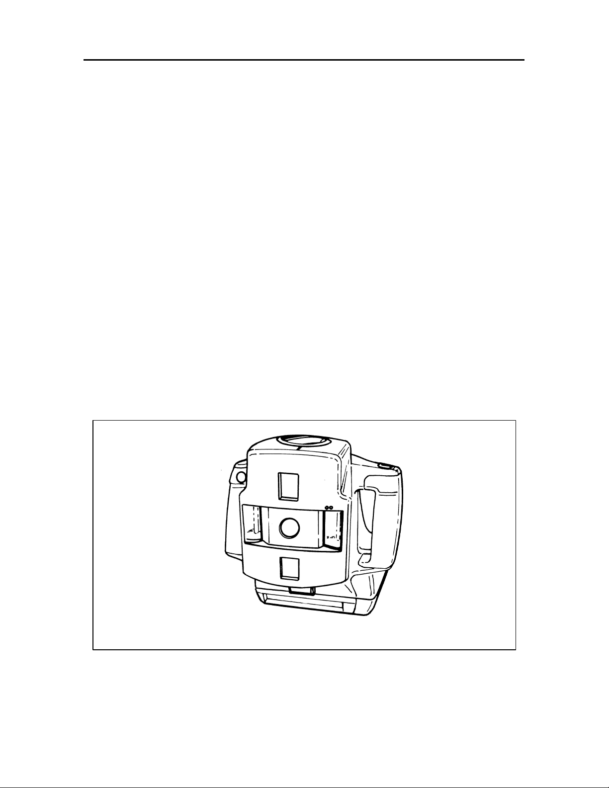
The Polaroid Macro 5 SLR (Figure 1-1) is a fully automatic, close-up portable
camera. It is designed for medical and dental documentation, quality control, law
enforcement, and other applications that requires close-up photographs.
The Macro 5 SLR has two built-in electronic flash units that provide even
illumination. It also has a microprocessor-controlled exposure system that
automatically sets the camera for correct exposure at all magnification settings.
The Macro 5 SLR produces automatic exposures at:
• 0.2x (20%)
• 0.4x (40%)
• 1x (100%)
• 2x (200%)
• 3x (300%)
The lens for each exposure setting is self-contained within the camera's manually
rotating turret, so there is no need to attach any accessories when changing
camera magnification.
Figure 1-1 Macro 5 SLR Camera
8
Page 9

Repair Manual
Features
Camera
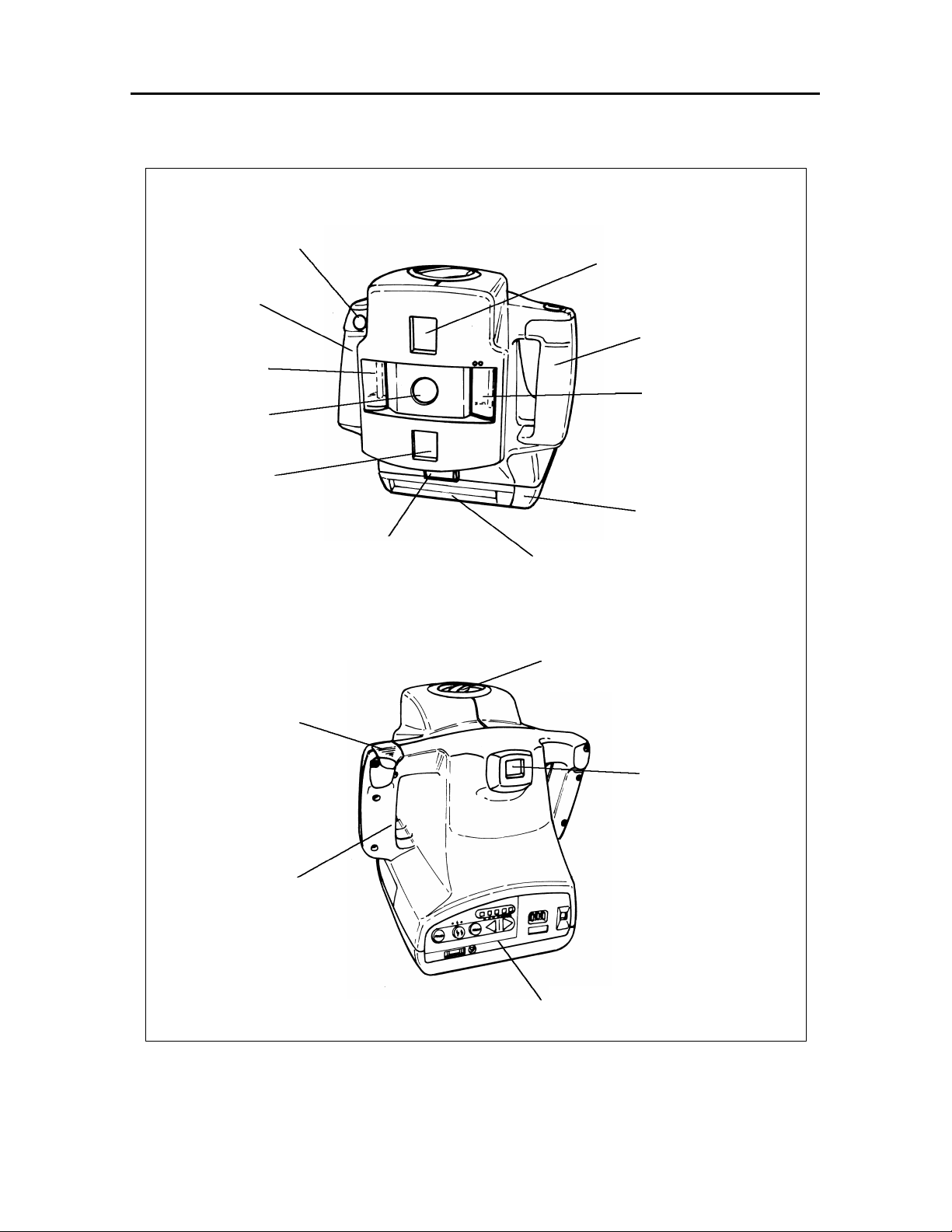
Basic Macro 5 SLR features include: (Figure 1-2)
• Camera Back (Film Holder)
• Film Door Release Button
• Two Built-In Electronic Flash Units
• Lens
• Dual Light Rangefinder (Ranging Lights)
• Viewfinder
• Grid Screen in Viewfinder
• Tripod or Copystand Socket (on bottom of camera)
• Battery Compartment Door
• Battery Compartment (inside hand grip)
• Right/Left Hand Grips
• Magnification Selector Knob
• Shutter (S1) Button
Macro 5 SLR Camera
Table 1-1 describes the Macro 5 SLR features.
Table 1-1. Macro 5 SLR Camera Features
Camera Feature Description
Camera Back The camera back is a modified ProCam
camera back.
Film Door The film door release button opens the
Release Button camera back film door.
Lens The camera contains separate lens for
each magnification setting. Each lens has
the proper focal length for minimum
perspective distortion and more working
space between the camera and the subject,
and a small aperture for better depth of
field.
9
Page 10
Repair Manual
Electronic
Selector
Battery
Macro 5 SLR Camera
Shutter Button
Right Hand
Grip
Electronic
Flash
Lens
Rangefinder
Aim Light
Film Door Release
Button
Rangefinder
(Aim Light)
Left Hand Grip
Flash
Camera Back
Camera Back
Door
Magnification
Battery
Compartment
Door
Viewfinder
Compartment
(inside grip)
Control Panel
Figure 1-2 Macro 5 SLR Features
10
Page 11

Repair Manual
Macro 5 SLR Camera
Table 1-1. Macro 5 SLR Camera Features (Cont’d)
Camera Feature Description
Two Built-In The two built-in electronic flash units
Electronic Flash Units provide even illumination at all
magnification settings.
Either flash unit can be turned off if side
lighting is needed to show texture or
elevation.
Note: The light output from the remaining
flash unit will be increased to
produce the correct exposure.
Both built-in electronic flash units can also
be turned off and auxiliary lighting used.
The auxiliary light is connected to the
auxiliary receptacle on the control panel
located on the back of the camera.
Dual-Light Rangefinder The dual-light rangefinder is used to focus
(Ranging Lights) the camera.
To properly focus the camera, it should be
moved nearer or farther from the subject
until the two ranging lights merge.
Viewfinder The viewfinder shows the area included in
the picture.
Use of the grid ensures consistent framing.
Grid Screen in Viewfinder The grid screen in viewfinder aids in
consistent framing of subject.
Tripod Socket Standard tripod socket located on bottom
of camera..
11
Page 12

Repair Manual
Macro 5 SLR Camera
Table 1-1. Macro 5 SLR Camera Features (Cont’d)
Camera Feature Description
Battery Compartment Door The battery compartment slides open to
replace the four (4) Alkaline batteries in the
Battery compartment.
Battery Compartment The battery compartment contains four (4)
AA batteries that provides power for the
dual-light rangefinder.
Note: Alkaline batteries (Standard or
rechargeable) are recommended.
Rechargeable NiCad batteries can
also be used.
Right/Left Hand Grips The right/left hand grips allow the operator
to hold the camera steady during subject
framing and picture-taking.
Note: The battery compartment is located
in the right hand grip.
Magnification Selector Knob The magnification selector knob selects the
desired magnification setting for the
camera. It clicks into position at each
magnification setting.
Note: If the magnification selector is
improperly set (between settings),
the camera will not function.
The selector knob also shows the
camera-to-subject distance and
icons that represent the approximate area of a subject included in
the picture.
12
Page 13

Repair Manual
Macro 5 SLR Camera
Table 1-1. Macro 5 SLR Camera Features (Cont’d)
Camera Feature Description
Red Shutter (S1) Button The red shutter (S1) button turns on the
ranging lights and actuates the shutter and
the flash unit/s when pressed.
Pressing the button lightly turns on the
camera and the two ranging lights used to
focus the camera.
Note: The two ranging lights stay on as
long as the button is lightly pressed.
If the button is released, the two
ranging lights go off in approximately
fifteen (15) seconds. Pressing the
shutter button all the way in takes
the picture (actuates the shutter and
flash units).
Note: It will functional as a shutter button
only if the camera is ready (focused
properly and flash fully charged) to
take a picture as indicated by the
green status lights.
13
Page 14
Repair Manual
Macro 5 SLR Camera
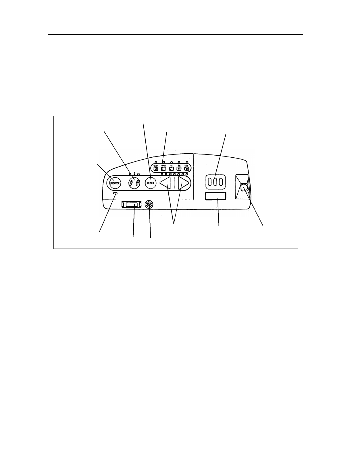
Control Panel
Figure 1-3 shows the Macro 5 SLR control panel. Table 1-2 describes its
features.
Reset Button
Flash Control
Button/Status Lights
Power Button
Magnification
Indicators
Date/Time Selector
Buttons
Low Battery
Status Light
RS232
Receptacle
Lighten/Darken
Controls
Auxiliary Flash
Receptacle
Figure 1-3 Control Panel
Date/Time
Display
Picture
Counter
14
Page 15

Repair Manual
Macro 5 SLR Camera
Table 1-2. Control Panel Features
Camera Feature Description
POWER Button Turns the camera On. The flash units
begin charging. The camera turns off if the
power button is pressed again, or after 30
seconds of inactivity.
Note:The camera can also be turned on
by slightly pressing the shutter (S1)
button.
Low Battery Lights up when the batteries are low.
Status Light The ranging lights also become dim.
Flash Control Selectively turns the flash units on or off.
Button/Status lights (Normally both flash units are turned on.)
The red charging status light above the
flash control button blinks while the flash
units are charging. The green status lights
comes on when the flash unit/s are fully
charged (ready).
Press the flash control button once to turn
off the right flash unit; press it a second
time to turn off the left flash unit; press it a
third time to turn off both flash units.
RESET Button Resets the camera to the nominal flash and
lighten/darken settings for the current
magnification.
Note:The camera has a memory and
returns to the custom settings for
each magnification when it is turned
on.
15
Page 16

Repair Manual
Macro 5 SLR Camera
Table 1-2. Control Panel Features (Cont’d)
Camera Feature Description
Lighten/Darken Controls Makes the picture lighter or darker.
Each setting increases or decreases
exposure by 1/3 f-stop. The center light is
the nominal setting.
Pressing the white arrow lightens the
picture (increases exposure); pressing the
black arrow darkens the picture (decreases
exposure).
Magnification Status Lights Lights up to indicate the selected
magnification setting.
RS232 Receptacle Standard computer receptacle used to
connect a computer to the camera so that
the diagnostic utility program can be used
to troubleshoot camera failures. Refer to
the troubleshooting section in this service
manual for more details.
Picture Counter Shows how many picture remain in the film
pack.
Initially the picture counter reads ten (10).
As pictures are taken, the counter
automatically counts down to show how
many pictures remain.
16
Page 17

Repair Manual
Macro 5 SLR Camera
Table 1-2. Control Panel Features (Cont’d)
Camera Feature Description
Auxiliary Flash Receptacle Standard PC socket for an auxiliary flash.
Notes: • An electronic flash must be used
for auxiliary lighting. Do Not use
tungsten, halogen, or fluorescent
lights.
• The built-in flash can be combined with auxiliary lighting.
• Test exposures may be needed
to determine the proper lighten or
darken setting for correct
exposure.
Date/Time Display Displays the selected date/time sequence.
Date/Time Selector Buttons Selects the desired date/time sequence to
be printed on the picture.
Note: Refer to the Macro 5 SLR User's
Guide for information on how to
select or set the current date/time
desired.
17
Page 18

Repair Manual
Macro 5 SLR Camera
Specifications
Operating Power Ranging Lights: Four (4) AA Alkaline batteries
(standard or rechargeable)
Camera: Film pack battery.
Flash Unit Two built-in flash units.
Shutter Speed Fixed (1/50 second).
Polaroid Film Types Polaroid High Definition.
Type Film: 990
Grid
Spectra/Image
Note: These high-speed (ISO640/290)
film types are balanced for electronic
flash and daylight (55000K), and
produce positive color prints.
Camera Back Modified ProCam camera back.
Note: Never substitute with standard ProCam
camera back.
Date Display Five printable type of date sequences:
• No Print Mode - - -
• Month/date/year 8 7 '95
• Day/month/year 7 8 '95
• Year/month/day '95 8 7
• Day/time (24-hour clock) 7 13:30
18
Page 19

Repair Manual
Macro 5 SLR Camera
Specifications (Cont’d)
Magnification: Lens-to-subject Lens focal Effective lens Depth
distance length
2
aperture of field
3
0.2x (20%) 52in./130cm 221mm f/20 10.6in./27cm
0.4x (40%) 26in./66cm 188mm f/34 3.8in./10cm
1x (100%) 9.9in./25cm 128mm f/47 0.86in./2.2cm
2x (200%) 4.8in./13cm 85.4mm f/67 0.31in./0.8cm
3x (300%) 3.1in./8cm 64mm f/100 0.20in./0.5cm
Viewfinder Built-in grid screen for consistent
framing of subjects.
Rangefinder Dual-lights for focusing.
Memory Internal electronic memory. Camera returns to
custom settings for each magnification when it
is turned on.
Weight 4 lbs. (1.8kg)
Dimensions Height- 9 inches (23cm)
Width - 9 inches (23cm)
Depth - 8.7 inches (22cm)
Accessories Polarizer Kit:
Reduces reflections from flash units when
taking pictures of glossy or glass subjects.
Fluorescein Kit:
For external ophthalmic photography includes
#2A yellow barrier filter and #47A blue exciter
filters.
19
Page 20

Repair Manual
Macro 5 SLR Camera
Section 2. Theory of Operation
Operation ........................................................................................................... 21
Camera Setup................................................................................................. 21
Picture Taking................................................................................................. 24
20
Page 21

Repair Manual
Macro 5 SLR Camera
Operation
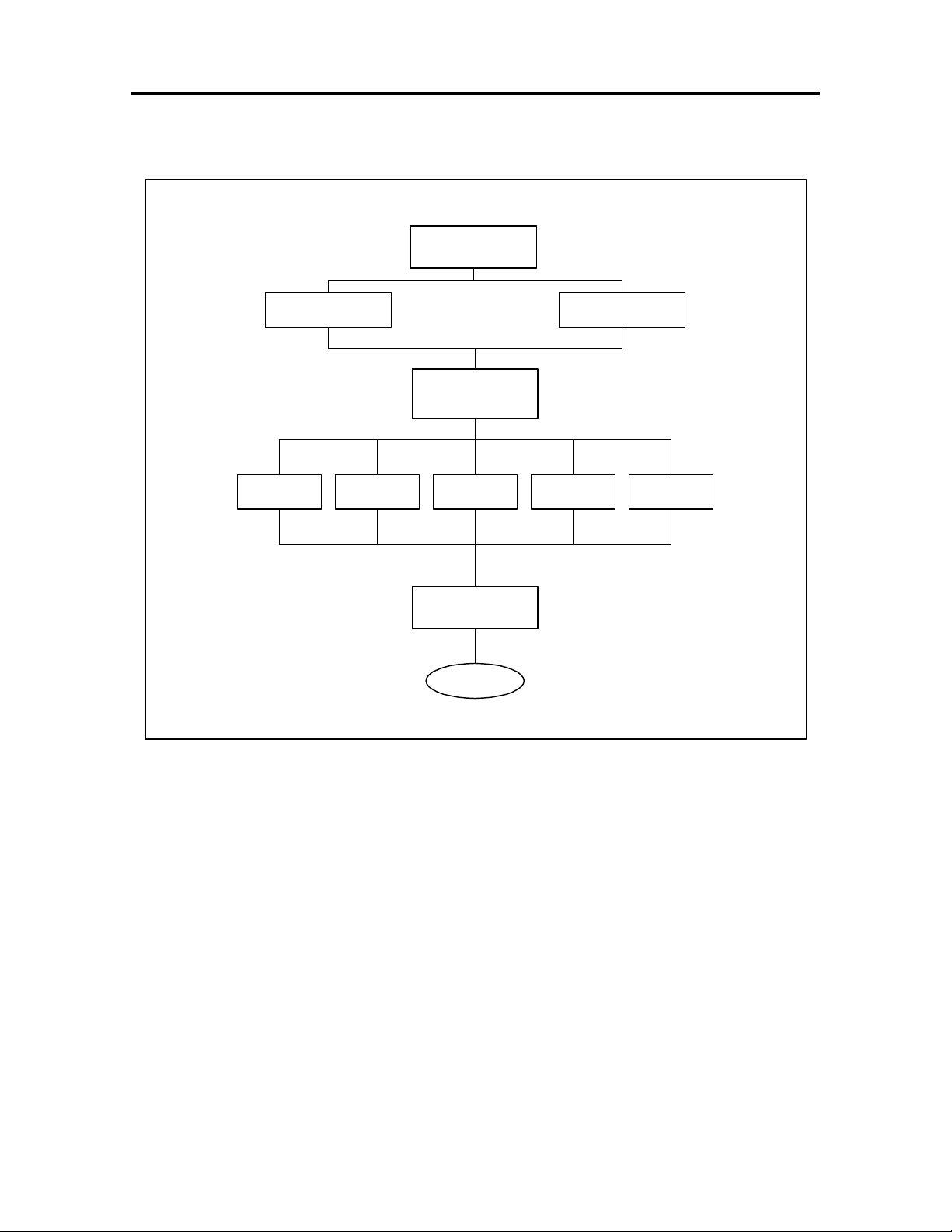
The following procedures sequentially detail the picture taking operation. For a
simplified explanation of this picture taking operation refer to the flow diagrams in
Figures 2-1 and 2-2.
Camera Setup
1. Set the camera to the desired magnification.
Note: If the magnification selector is improperly set (between settings), the
camera will not function. For detailed information on how to select
magnification, refer to the Macro 5 SLR User's Guide.
Magnification: Lens-to-subject Lens focal Effective lens Depth
distance length
2
aperture of field
3
0.2x (20%) 52in./130cm 221mm f/20 10.6in./27cm
0.4x (40%) 26in./66cm 188mm f/34 3.8in./10cm
1x (100%) 9.9in./25cm 128mm f/47 0.86in./2.2cm
2x (200%) 4.8in./13cm 85.4mm f/67 0.31in./0.8cm
3x (300%) 3.1in./8cm 64mm f/100 0.20in./0.5cm
2. If applicable, plug in desired filter kit (Polarizer or Fluorescein).
Note: Use of specified filter kit is optional. For detailed information, refer to
the provided Macro 5 SLR User's Guide.
Filter Kit:
Polarizer: Reduces reflections from flash units when taking pictures of
glossy or glass subjects.
Fluorescein: For external ophthalmic photography includes #2A yellow
barrier filter and #47A blue exciter filters.
21
Page 22

Repair Manual
Macro 5 SLR Camera
3. Set the lighten/darken buttons to the desired exposure (trim).
Notes: • Makes the picture lighter or darker to enhance the specific details
of the subject.
• Normally the camera provides the correct exposure for subjects of
average brightness.
• Each setting adjusts the flash output by 1/3 f-stop. The center
light is the nominal setting.
• White arrow lightens the picture (increases exposure).
• Black arrow darkens the picture (decreases exposure).
4. Set date/time selector buttons to the desired date/time sequence to be printed
on the picture.
Note: This function is optional. It can be shut off if desired. For detailed
information on how to select, or set, the current date/time, refer to the
Macro 5 SLR User's Guide.
Date Display: The five printable date sequences are as follows:
• No Print Mode - - -
• Month/date/year 8 7 '95
• Day/month/year 7 8 '95
• Year/month/day '95 8 7
• Day/time (24-hour clock) 7 13:30
5. Set the flash control buttons (left/right or both). The red charging status light
above the flash control button blinks while the flash units are charging. The
green status lights come on when the flash unit/s are fully charged (ready).
Note: Normally both flash units will be on. For detailed information on how to
select either the left or right flash, refer to the Macro 5 SLR User's
Guide.
22
Page 23
Repair Manual
Macro 5 SLR Camera
Camera Set-Up
Install batteries
Exposure Strobe(s)
Load film pack
Set camera
parameters
Date/Time FilterMagnification
Take Picture
To Figure 2-2
Figure 2-1 Camera Setup
23
Page 24

Repair Manual
Macro 5 SLR Camera
Picture Taking
1. Turn on the camera by lightly pressing the shutter (S1/S2 switch) button. This
closes the S1 switch.
Closing the S1 switch:
• Turns on the top and bottom range (aim) lights to focus the camera.
• Latches the camera's power on.
• Starts the strobe charge cycle (charged before self-check routine started).
• Starts the camera's self-check routine.
Notes: If the shutter button is pressed all the way in at this time, the
camera's electronics inhibit it from taking a picture (camera beeps
indicating strobes not charged). The strobes must be fully charged
and the camera’s status lights must be green indicating that the
camera is ready before a picture can be taken.
The two range lights stay on as long as the button is lightly pressed.
If the button is released, the two range lights go off in approximately
fifteen (15) seconds. Press the shutter button lightly to turn them on
again.
2. During this self-check routine, the microprocessor controller initializes (resets)
the camera's electronics and checks the status of:
• Control panel settings
• Magnification setting - position of turret (remembers last magnification
setting)
• Lighten/Darken (remembers last exposure setting)
• Film door (open/closed)
• RS232 receptacle (connected or not connected)
• Battery (low?)
• Picture count (0?)
• End-of-pack
• Auxiliary receptacle (connected or not connected)
• Internal timer (updated)
• Strobes (charged/not charged)
Note: This self-check routine starts a thirty (30) second continuous test loop
that times out if no action is taken. It continually checks the status of
the camera. If no action is taken during this thirty (30) second
continuous test loop, the camera automatically powers down (shuts
off). It takes an action (button pressed, setting changed, picture
taken, etc.) to keep it powered up.
24
Page 25

Repair Manual
Macro 5 SLR Camera
3. While this self-check routine is checking the camera's status, focus and frame
the subject.
For detailed information on how to properly focus and frame the subject, refer
to the Macro 5 SLR User's Guide.
4. Once the camera is properly focused and the status lights are green, press
the shutter button (S1/S2) all the way in to take the picture. This action
closes the S2 switch.
Closing the S2 switch:
• Fires the strobes.
• Actuates the shutter.
Note: The camera will take a picture only when it is properly focused, the
strobes are fully charged, and the self-check routine is in progress.
5. The picture will automatically eject from the camera when the shutter button is
released.
Note: The camera powers down (shuts off) when:
• Picture count reaches zero (0).
• Self-check continuous loop times out - no camera activity for thirty
(30) seconds (button pressed, setting changed, picture taken,
etc.).
25
Page 26

Repair Manual
Macro 5 SLR Camera
From Figure 2-1
If S1 button released, range
lights go out in 15 seconds.
Press S1 button lightly to turn
on again.
Range lights ON
Power latches ON
Strobes charge
Press shutter
button S1/S2
Picture Taking
Lightly press shutter
button S1/S2
S1 closes
Green status lights On
(Ready)
Status OK
Self-check routine
starts
Checks status of:
- Control panel settings
- Magnification settings
- Lighten/Darken setting
- Film door
- RS232 receptacle
- Battery
- Picture count
- End-of-pack
- Auxiliary receptacle
- Internal timer
- Strobes
30 second
continuous
loop
Strobes not
charged
Warning
beep
Strobes
charged
S2 closes
- Strobes fire
- Shutter actuates
Picture
taken
Figure 2-2 Picture Taking
Camera powers down (shuts off) when:
- Picture counter reaches zero (0)
- Self-check continuous loop times out (no
camera activity for 30 seconds - button
pressed, setting changed, picture taken, etc.)
26
Page 27

Repair Manual
Macro 5 SLR Camera
Section 3. Adjustments
Ranging (Aim) Lights Adjustment....................................................................... 28
Grid Adjustment.................................................................................................. 31
27
Page 28

Repair Manual
Ranging (Aim) Lights Adjustment
1. Place the camera onto the test fixture as shown in Figure 3-1.
Camera
Macro 5 SLR Camera
Test Target
area
Test Fixture
Figure 3-1 Camera Test Fixture
2. Set the magnification selector knob to its 1X position.
3. Turn on the camera.
4. Press the red shutter button lightly to turn on the range lights. The range
lights should be merged together and centered in the test target (Figure 3-2).
Note: If the range lights are merged together and centered in the test
target, no adjustment is necessary.
If the range lights are not merged together or centered in the test
target, proceed to step 5 and adjust as needed.
28
Page 29

Repair Manual
Macro 5 SLR Camera
Figure 3-2 Range Light Adjustment
5. Adjust range lights as follows:
• Remove the front cover as explained in section 4 of this service manual.
• Determine which range light is out of adjustment.
• Loosen the applicable adjustment screw (Figure 3-3) and then manually
adjust the range light until it merges with the other range light.
Note: If either range light filament is not horizontal (Figure 3-2),
loosen the applicable range light clamp screw and then manually
rotate the lamp until its filament is correctly positioned.
6. Once both range lights are merged together and properly centered in the test
target, tighten the range light adjustment screws being careful not to disturb
the adjustment.
7. Recheck the position of the range lights by lightly pressing the red shutter
button. The range lights should be merged together and centered in the test
target. If necessary, repeat steps 5 through 7 until the range lights are
properly merged and centered.
29
Page 30

Repair Manual
Macro 5 SLR Camera
Clamp
Clamp
Screw
Up/Down
Adjustment
Side-to-Side
Adjustment
Figure 3-3 Range Light Adjustments
30
Page 31

Repair Manual
Macro 5 SLR Camera
Grid Adjustment
Note: Make sure the range lights are properly adjusted before adjusting the
camera grid.
1. Take a picture of the test target.
2. Using a felt tip pen, draw diagonal lines from corner-to- corner on the picture
of the test target (Figure 3-4).
Correct Incorrect
Figure 3-4 Grid Position
Notes: • If the diagonal lines intersect in the center of the grid pattern, no
adjustment is needed.
• If the diagonal lines do not intersect in the center of the grid pattern,
proceed to step 3 and adjust the position of the grid as needed.
3. Manually adjust the position of the grid as follows:
• If applicable, remove the front cover as explained in section 5 of this
service manual.
• Turn the applicable adjustment screw (Figure 3-5) until the grid is properly
centered.
4. Repeat steps 1 through 4 until the grid is properly centered.
31
Page 32

Repair Manual
Up/Down
Adjustment
Macro 5 SLR Camera
Screw
Side-to-Side
Adjustment
Screw
Figure 3-5 Grid Adjustments
32
Page 33

Repair Manual
Macro 5 SLR Camera
Section 4. Troubleshooting
Diagnostics Module............................................................................................ 34
33
Page 34

Repair Manual
Macro 5 SLR Camera
Diagnostics Module
A diagnostics module is currently being created. This module is a CD, titled
Module 5 Star, that will assist in diagnosing camera malfunctions. It will be
available shortly. For ordering, the part number is CPS506.
34
Page 35

Repair Manual
Macro 5 SLR Camera
Section 5. Parts Replacement
Required Tools and Equipment.......................................................................... 37
Electrostatic Discharge Warning........................................................................ 38
Inspection and Cleaning..................................................................................... 38
Disassembly/Assembly of Camera..................................................................... 38
Left/Right Cover (Includes Front Cover)............................................................. 39
1. Removal (Figure 5-1, 5-2 and 5-2a).......................................................... 39
2. Reassembly............................................................................................... 42
Front Cover........................................................................................................ 43
1. Removal (Figure 5-3) ................................................................................ 43
2. Reassembly............................................................................................... 44
Rear Cover......................................................................................................... 45
1. Removal (Figures 5-2 and 5-4) ................................................................. 45
2. Reassembly............................................................................................... 46
Bottom Cover ..................................................................................................... 47
1. Removal (Figure 5-5) ................................................................................ 47
2. Reassembly............................................................................................... 48
Strobe PC Board................................................................................................ 49
1. Removal (Figure 5-6) ................................................................................ 49
2. Reassembly............................................................................................... 50
Trigger PC Boards ............................................................................................. 51
1. Removal (Figure 5-7) ................................................................................ 51
2. Reassembly............................................................................................... 52
S1/S2 PC Board................................................................................................. 53
1. Removal (Figure 5-8) ................................................................................ 53
2. Reassembly............................................................................................... 54
Control Panel ..................................................................................................... 55
1. Removal (Figure 5-9) ................................................................................ 55
2. Reassembly............................................................................................... 56
35
Page 36

Repair Manual
Macro 5 SLR Camera
Logic PC Board.................................................................................................. 57
1. Removal (Figure 5-10) .............................................................................. 57
2. Reassembly............................................................................................... 58
Camera Back ..................................................................................................... 59
1. Removal (Figure 5-11) .............................................................................. 59
2. Reassembly............................................................................................... 60
Encoder Plate and PC Board............................................................................. 62
1. Removal (Figure 5-12 and 5-12a) ............................................................. 62
2. Reassembly............................................................................................... 64
Turret Assembly................................................................................................. 65
1. Removal (Figure 5-13) .............................................................................. 65
2. Reassembly............................................................................................... 66
Shutter Solenoid Assembly................................................................................ 67
1. Removal (Figure 5-14) .............................................................................. 67
2. Reassembly............................................................................................... 68
Bulb (Aim Light) Bracket Assembly.................................................................... 69
1. Removal (Figure 5-15) .............................................................................. 69
2. Reassembly............................................................................................... 70
Date Code Module............................................................................................. 71
1. Removal (Figure 5-16) .............................................................................. 71
2. Reassembly............................................................................................... 72
Firmware (Logic PC Board)................................................................................ 73
1. Removal (Figure 5-17) .............................................................................. 73
2. Reassembly............................................................................................... 74
36
Page 37

Repair Manual
Macro 5 SLR Camera
Required Tools and Equipment
• Pencil Soldering Iron
• Solder Sucker
• Anti-Static Mat and Wrist Strap
• Standard Tool Kit
• Torx Driver (6" Apex Torx T-10 Tip)
• Small Pair of Diagonal Cutters
• Cleaning Tissue or Soft Clean Rags
• Universal PLCC Extraction Tool (fits 20-84 pin Micro Controller)
37
Page 38

Repair Manual
Macro 5 SLR Camera
Electrostatic Discharge Warning
The camera circuitry can easily be damaged by static discharges. Always use an
anti-static mat and a wrist-strap when servicing the camera's PC Boards.
Inspection and Cleaning
Whenever disassembling the camera for parts replacement, always inspect the
following assemblies for dust and debris (reagent developer).
Note: If necessary, clean the replaced parts with a water dampened tissue or
soft clean rag to assure that dust and debris (reagent developer)
do not interfere with camera performance.
• Front Cover Assembly
• Camera Back Rollers
• Turret Assembly
• Cone Assembly
• Shutter Assembly
• Viewfinder Assembly
Disassembly/Assembly of Camera
This section of the Service Manual describes disassembly/reassembly
procedures. Before performing any of these procedures, always make sure that
the camera is turned off and the film pack is removed.
CAUTION
To prevent any chance of electric shock, the camera should be opened only by
a qualified service person, and only after it has been disconnected from its
power source (film pack battery); make sure the strobe capacitors are fully
discharged (dumped). Also, take care not to damage (bend or distort) any of
the camera components during disassembly and reassembly.
38
Page 39

Repair Manual
Macro 5 SLR Camera
Left/Right Cover (Includes Front Cover)
1. Removal (Figure 5-1, 5-2 and 5-2a)
a. Turn off power by pressing the POWER button on the camera's control
panel.
b. Disconnect the camera’s power source as follows: Slide the battery cover
open, unsnap the battery cable clip, and lift out the battery holder.
c. If applicable, remove the film pack from the camera back.
d. Using a torx driver, remove the single screw securing the turret knob to
the top of the turret assembly. Lift off the turret knob.
e. Using a torx driver, remove the single screw securing the left/right covers
to the top of the turret assembly.
f. Using a torx driver, remove the three (3) screws securing the left hand
grip to the left cover. Lift off the left hand grip.
g. Using a torx driver, remove the three (3) screws securing the right hand
grip to the right cover. Lift off the right hand grip.
h. Unsnap the film door button adapter and lift it out.
i. Remove the adhesive vinyl pad from the bottom of the camera back.
39
Page 40

Repair Manual
Turret Knob
Macro 5 SLR Camera
Turret
Assembly
Vinyl Pad
Door Button
Adapter
Front Cover
Assembly
Figure 5-1 Camera Disassembly
j. Using a torx driver, remove the screw securing the bottom of the right
cover to the camera back (Figure 5-2).
k. Using a torx driver, remove the screw securing the bottom of the left cover
to the camera back (Figure 5-2).
l Disconnect the battery cable from the left cover tie post.
m Using both hands, gently pry open and then left out the left/right cover
assembly.
40
Page 41

Repair Manual
Note: Front cover assembly is still attached to the left/right cover
assembly.
n Disconnect both trigger cables (J31) from the trigger PC boards
(Figure 5-2a).
Note: This should free the left/right - front cover assembly from the rear
cover and camera back.
Macro 5 SLR Camera
Screw
location
for Rear
Cover
Screw
location
for Left
Cover
Screw
location
for Rear
Cover
Screw
location
for Right
Cover
Figure 5-2 Left/Right Bottom Screw Location
To J31
To J31
Figure 5-2a Trigger Cables
41
Page 42

Repair Manual
Macro 5 SLR Camera
2. Reassembly
a. Connect the trigger cables (J31) to its applicable trigger PC boards.
Note: Make sure each cable is properly dressed and secured by the white
cable clamps attached to the side of the left/right cover.
b. Using both hands, gently install the left/right cover assembly (includes the
front cover) onto the camera back making sure that it properly aligns with
each bottom screw hole and that it properly fits around the turret
assembly.
c. Connect the battery cable to its left cover tie post.
d. Using a torx driver, install and tighten the screw that secures the bottom of
the right cover to the camera back (Figure 5-2).
e. Using a torx driver, install and tighten the screw that secures the bottom of
the left cover to the camera back (Figure 5-2).
f. Install the film door button adapter. It should snap into place.
g. Using a torx driver, install and tighten the three (3) screws that secure the
right hand grip to the right cover.
Note: Be careful not to pinch the battery cable between the right hand
grip and its cover.
h. Using a torx driver, install and tighten the three (3) screws that secures the
left hand grip to the left cover.
Note: Be careful not to pinch the S1/S2 cable between the left hand grip
and its cover.
i. Using a torx driver, install and tighten the single screw that secures the
left/right covers to the top of the turret assembly.
j. Using a torx driver, install and tighten the single screw that secures the
turret knob to the top of the turret assembly.
k. Install a new adhesive vinyl pad (Part Number 1B6614A) to the bottom of
the camera back.
l. Connect the camera’s power source: Install the battery holder, snap
battery cable clip onto hjolder connection, slide battery cover closed.
42
Page 43

Repair Manual
Macro 5 SLR Camera
Front Cover
1. Removal (Figure 5-3)
a. Remove the left/right cover assembly as explained on page 39.
b. Using a torx driver, remove the four (4) screws securing the front cover to
the left/right covers.
c. Lift off the front cover.
Left Cover
Right Cover
Front Cover
Figure 5-3 Front Cover
43
Page 44

Repair Manual
Macro 5 SLR Camera
2. Reassembly
a. Using a torx driver, install and tighten the four (4) screws that secure the
front cover to the left/right covers.
b. Install the left/right cover assembly as explained on page 42.
44
Page 45

Repair Manual
Macro 5 SLR Camera
Rear Cover
1. Removal (Figures 5-2 and 5-4)
a. Remove the left/right cover assembly as explained on page 39.
b. Using a torx driver, remove the screw securing the bottom of the rear
(right side) cover to the camera back (Figure 5-4).
c. Using a torx driver, remove the screw securing the bottom of the rear (left
side) cover to the camera back (Figure 5-4).
d. Gently lift off the rear cover from the camera back.
Rear Cover
Camera Back
Figure 5-4 Rear Cover
45
Page 46

Repair Manual
Macro 5 SLR Camera
2. Reassembly
a. Install the rear cover to the camera back.
b. Using a torx driver, install and tighten the screw that secures the bottom of
the rear (left side) cover to the camera back.
c. Using a torx driver, install and tighten remove the screw that secures the
bottom of the rear (right side) cover to the camera back.
d. Install the left/right cover assembly as explained on page 42.
46
Page 47

Repair Manual
Macro 5 SLR Camera
Bottom Cover
1. Removal (Figure 5-5)
a. Remove the left/right cover assembly as explained on page 39.
Note: This assembly includes the front cover.
b. Remove the rear cover as explained on page 45.
c. Remove the camera back door.
Note: Refer to the user's guide for instructions on how to remove the
camera back door.
d. Using a torx driver, remove the three (3) remaining screws securing the
bottom cover to the camera back.
e. Gently lift the bottom cover from the camera back.
Figure 5-5 Bottom cover
47
Page 48

Repair Manual
Macro 5 SLR Camera
2. Reassembly
a. Place the bottom cover onto the camera back making sure that its two (2)
alignment holes properly align with the support posts on the camera back..
b. Using a torx driver, install and tighten the three (3) screws securing the
bottom cover to the camera back.
c. Install the camera back door.
Note: Refer to the user's guide for instructions on how to install the
camera back door.
d. Install the rear cover as explained on page 46.
e. Install the left/right cover assembly as explained on page 42.
48
Page 49

Repair Manual
Macro 5 SLR Camera
Strobe PC Board
Caution: Shock Hazard - High Voltage
Note: Use a dump stick to fully discharge the strobe capacitors before
attempting to remove or replace the strobe PC board.
1. Removal (Figure 5-6)
a. Remove the left/right cover assembly as explained on page 39.
b. Remove the rear cover as explained on page 45.
c. Disconnect the following electrical cables from the Strobe PC board:
• J41 (Goes to the left trigger PC board)
• J42 (Goes to the right trigger PC board)
• J43 (Goes to the Logic PC board)
• J44 (Goes to the Logic PC board)
d. Lift out the strobe PC board.
Strobe
PC Board
Figure 5-6 Strobe PC Board
49
Page 50

Repair Manual
Macro 5 SLR Camera
2. Reassembly
a. Connect the following electrical cables:
• J41
• J42
• J43
• J44
b. Install the strobe PC board making sure that it is properly positioned in its
slotted bracket on the rear cover.
c. Install the rear cover as explained on page 46.
d. Install the left/right cover assembly as explained on page 42.
50
Page 51

Repair Manual
Macro 5 SLR Camera
Trigger PC Boards
Caution: Shock Hazard - High Voltage
Note: Use a dump stick to fully discharge the strobe capacitors before
attempting to remove or replace the trigger PC board.
1. Removal (Figure 5-7)
a. Remove the left/right cover assembly as explained on page 39.
b. Remove the front cover assembly as explained on page 43.
c. Disconnect electrical cable J32 from the applicable trigger PC board.
d. Using a soldering iron and a solder sucker, unsolder the white trigger wire
from the trigger coil.
Note: Be careful not to damage the trigger coil.
e. Using a torx driver, remove the two (2) screws securing the trigger PC
board to the front cover support mounts.
f. Lift out the trigger PC board.
51
Page 52

Repair Manual
White
Trigger
Macro 5 SLR Camera
Wire
Trigger PC
Boards
J32
Figure 5-7 Trigger PC Boards
2. Reassembly
a. Place the new the trigger PC board onto its front cover support mounts.
b. Using a torx driver, install and tighten the two (2) screws that secure the
trigger PC board to its front cover support mounts.
c. Connect electrical cable J32 to the trigger PC board.
d. Using a soldering iron, solder the white trigger wire to the trigger coil.
Note: Be careful not to damage the trigger coil.
e. Install the front cover assembly as explained on page 44.
f. Install the left/right cover assembly as explained on page 42.
52
Page 53

Repair Manual
Macro 5 SLR Camera
S1/S2 PC Board
1. Removal (Figure 5-8)
a. Remove the left/right cover assembly as explained on page 39.
b. Using a small pair of diagonal pliers, cut the ty-wrap securing the S1/S2
electrical cable to the right strobe cable.
c. Disconnect electrical cable J19 from the logic PC board at rear of camera.
d. Using a torx driver, remove the four (4) screws securing the S1/S2 PC
board to the right hand grip support mounts.
e. Lift out the S1/S2 PC board.
Note: Be careful not to lose the S1/S2 button spring.
S1/S2
Button
To J19 on
Logic Board
Screws (4)
S1/S2 Button
Spring
Figure 5-8 S1/S2 PC Board
53
Page 54

Repair Manual
Macro 5 SLR Camera
2. Reassembly
a. Place the new the S1/S2 PC board onto its right hand grip support
mounts.
Note: Make sure the large end of the S1 button spring is inserted into the
S1 button before the S1/S2 PC board is placed onto its support
mounts.
b. Using a torx driver, install and tighten the four (4) screws that secure the
S1/S2 PC board to its right hand grip support mounts.
c. Connect electrical cable J19 to the logic PC board.
d. Using a small ty-wrap, secure the S1/S2 electrical cable to the right strobe
cable.
e. Install the left/right cover assembly as explained on page 42.
54
Page 55

Repair Manual
Macro 5 SLR Camera
Control Panel
Caution: Shock Hazard - High Voltage
Note: Use a dump stick to fully discharge the strobe capacitors before
attempting to remove or replace the control panel.
1. Removal (Figure 5-9)
a. Remove the left/right cover assembly as explained on page 39.
b. Remove the rear cover assembly as explained on page 45.
c. Remove the bottom cover as explained on page 47.
d. Disconnect the white ribbon cable from the logic PC board.
e. Gently pull out the control panel. (This disconnects the control panel from
male connector J27 on the logic PC board).
f. Disconnect electrical cable J11 (X-Sync IN/OUT) from the logic PC board.
Note: Be careful not to break the two black wires soldered to the
X-Sync receptacle on the control panel.
White Ribbon
Cable
Control
Panel
Logic PC
Board
J11 Electrical
Cable
Figure 5-9 Control Panel
55
Page 56

Repair Manual
Macro 5 SLR Camera
2. Reassembly
a. Connect electrical cable J11 (X-Sync IN/OUT) to the logic PC board.
Note: Be careful not to break the two black wires soldered to the
X-Sync receptacle on the control panel.
b. Align the two (2) posts on the control panel with the holes on the logic PC
board and then gently push in the control panel. (This connects male
connector J27 on the logic PC board with the control panel).
Note: When pushing the control panel onto male connector J27 on the
logic PC board be careful not to damage (bend or distort) the
connectors pins.
c. Connect the white ribbon cable to the logic PC board.
d. Install the bottom cover as explained on page 48.
e. Install the rear cover assembly as explained on page 46.
f. Install the left/right cover assembly as explained on page 42.
56
Page 57

Repair Manual
Macro 5 SLR Camera
Logic PC Board
Caution: Shock Hazard - High Voltage
Notes: • Use a dump stick to fully discharge the strobe capacitors before
attempting to remove or replace the control panel.
• The logic PC board firmware (CPU chip) can easily be damaged by
static discharges. Always use an anti-static mat and a wrist-strap
when removing or replacing it.
1. Removal (Figure 5-10)
a. Remove the left/right cover assembly as explained on page 39.
b. Remove the rear cover assembly as explained on page 45.
c. Remove the bottom cover as explained on page 47.
d. Remove the control panel as explained on page 55.
e. Disconnect the following electrical cables from the logic PC board:
• J13 (Shutter Solenoid)
• J14 (Aim Lights)
• J15 (Piezo)
• J17 (Strobe Control)
• J18 (Strobe Data)
• J21 (VBat - Film Pack Battery)
• J23 (Film Door Switch)
• J24 (Encoder PC Board)
• J25 (Camera Back Flex)
f. Gently slide out the logic PC board.
57
Page 58

Repair Manual
Macro 5 SLR Camera
Logic PC
Board
Figure 5-10 Logic PC Board
2. Reassembly
a. Gently slide in the logic PC board making sure that its slot aligns with the
support hook on the camera back..
b. Connect the following electrical cables to the logic PC board:
• J13 (Shutter Solenoid)
• J14 (Aim Lights)
• J15 (Piezo)
• J17 (Strobe Control)
• J18 (Strobe Data)
• J21 (VBat - Film Pack Battery)
• J23 (Film Door Switch)
• J24 (Encoder PC Board)
• J25 (Camera Back Flex)
c. Install the control panel as explained on page 56.
d. Install the bottom cover as explained on page 48.
e. Install the rear cover assembly as explained on page 46.
f. Install the left/right cover assembly as explained on page 42.
58
Page 59

Repair Manual
Macro 5 SLR Camera
Camera Back
Caution: Shock Hazard - High Voltage
Note: Use a dump stick to fully discharge the strobe capacitors before
attempting to remove or replace the camera back.
1. Removal (Figure 5-11)
a. Remove the left/right cover assembly as explained on page 39.
b. Remove the rear cover assembly as explained on page 45.
c. Remove the bottom cover as explained on page 47.
d. If applicable, remove the strobe, control, or logic PC boards.
Note: Usually it is not necessary to remove the strobe and logic PC
boards and control panel when removing the camera back - just let
them dangle by their electrical cables. However, if these
components need to be removed during the removal of the camera
back, refer to the applicable disassembly procedures in this section
of the manual.
e. Disconnect the following electrical cables from the logic PC board:
• J15 (Piezo)
• J16 (Date Code Module)
• J23 (Film Door Switch)
• J25 (Camera Back Flex)
f. Using a torx driver, remove the six (6) screws securing the camera back to
the cone assembly.
g. Lift off the camera back.
Note: Be careful not to loose the plastic support plate (provides the
necessary screw holes that secure the left side of the cone to the
gear side of the camera back).
59
Page 60

Repair Manual
Macro 5 SLR Camera
Cone
Assembly
Camera Back
Figure 5-11 Camera Back
2. Reassembly
a. Place cone/turret assembly onto the camera back.
Notes: Make sure the:
• Cone alignment holes are properly located over the camera back
pins.
• Plastic support plate is properly positioned on the on the gear side
of the camera back; for proper screw hole alignment.
Support
Plate
• Strobe and logic PC boards, and control panel are properly
positioned on the camera back.
b. Using a torx driver, install and tighten the six (6) screws that secure the
camera back to the cone assembly.
60
Page 61

Repair Manual
c. Connect the following electrical cables from the logic PC board:
• J15 (Piezo)
• J16 (Date Code Module)
• J23 (Film Door Switch)
• J25 (Camera Back Flex)
Note: If it was necessary to remove the strobe and logic PC boards
and control panel during the removal of the camera back, make
sure that these components are properly reassembled. For
reassembly, refer to the appropriate assembly procedures in this
section of the manual.
d. Install the bottom cover as explained on page 48.
e. Install the rear cover assembly as explained on page 46.
f. Install the left/right cover assembly as explained on page 42.
Macro 5 SLR Camera
61
Page 62

Repair Manual
Encoder Plate
Macro 5 SLR Camera
Encoder Plate and PC Board
1. Removal (Figure 5-12 and 5-12a)
a. Remove the left/right cover assembly as explained on page 39.
b. Rotate the turret assembly to its 3x position to expose one of the screws
that secures the encoder plate to the lower turret plate.
c. Using a torx driver, remove the screw.
d. Rotate the turret assembly to its 1x position to expose the other screw that
secures the encoder plate to the lower turret plate.
e. Using a torx driver, remove the screw.
f. Gently slide out the encoder plate being careful not to break any of its
plastic sensor fingers.
g. Disconnect electrical cable from J24 on the logic PC board at rear of
camera.
h. Using a small flat screwdriver, gently pry up the front end of the encoder
PC board to release it from its support pins and then slide it out from its
support rails (Figure 5-12a).
Lower Turret
Plate
Figure 5-12 Encoder Plate and Lower Turret Plate
62
Page 63

Repair Manual
Macro 5 SLR Camera
Figure 5-12a Encoder PC Board
Encoder PC
Board
To J24 on
Logic Board
63
Page 64

Repair Manual
Macro 5 SLR Camera
2. Reassembly
a. Rotate the turret assembly to its 1x position.
b. Gently slide in the encoder plate making sure its mounting holes align with
the screw holes on the lower turret plate.
Note: Be careful not to break any of its plastic sensor fingers.
c. Using a torx driver, install and tighten the two (2) screws that secure the
encoder plate to the lower turret plate.
d. Rotate the turret assembly to its 3x position.
e. Align the front end of the encoder PC board with its support rails and then
gently push it in until it hits the support locking pins.
f. Using a small flat screwdriver, gently pry up the front end of the encoder
PC board and then push it in until it snaps onto its support locking pins.
g. Connect electrical cable J24 to the logic PC board.
h. Install the left/right cover assembly as explained on page 42.
64
Page 65

Repair Manual
Macro 5 SLR Camera
Turret Assembly
1. Removal (Figure 5-13)
a. Remove the left/right cover assembly as explained on page 39.
b. Remove the encoder plate and PC board as explained on page 62.
c. Using a pair of C-ring pliers, remove the top and lower pivot plate C-rings.
d. Pull out the top and lower turret bushings and then lift out the turret
assembly.
C-Ring
Turret
Bushing
Figure 5-13 Turret Assembly
65
Page 66

Repair Manual
Macro 5 SLR Camera
2. Reassembly
a. Slide the turret assembly onto its pivot pins and then insert the top and
lower turret bushings onto their respective pivot pins.
b. Using a pair of C-ring pliers, install the top and lower pivot plate C-rings to
secure the turret assembly to its pivot pins.
c. Install the encoder plate and PC board as explained on page 64.
d. Install the left/right cover assembly as explained on page 42.
66
Page 67

Repair Manual
Macro 5 SLR Camera
Shutter Solenoid Assembly
1. Removal (Figure 5-14)
a. Remove the left/right cover assembly as explained on page 39.
b. Disconnect the solenoid cable wires from the solenoid pins.
c. Using tweezers, disconnect the shutter extension spring from the shutter
pivot post.
d. Using a torx driver, remove the two (2) screws securing the solenoid
assembly to the viewfinder housing.
e. Lift out the solenoid assembly being careful not to lose the solenoid
plunger.
Solenoid
Extension
Spring
Figure 5-14 Shutter Solenoid Assembly
67
Page 68

Repair Manual
Macro 5 SLR Camera
2. Reassembly
a. Place the solenoid assembly onto the viewfinder support posts.
b. Using a torx driver, install and tighten the two (2) screws that secure the
solenoid assembly to the viewfinder housing.
c. Using tweezers, connect the shutter extension spring to the shutter pivot
post.
d. Connect the solenoid cable wires to the solenoid pins.
e. Install the left/right cover assembly as explained on page 42.
68
Page 69

Repair Manual
Bulb (Aim Light) Bracket Assembly
1. Removal (Figure 5-15)
a. Remove the left/right cover assembly as explained on page 39.
b. Remove the rear cover assembly as explained on page 45.
c. Disconnect electrical cable J14 from the logic PC board.
d. Using a torx driver, remove the screws securing the aim lights.
e. Pull out the aim light cable assembly - includes both aim lights.
Macro 5 SLR Camera
Figure 5-15 Aim Light Cable Assembly
69
Aim Light
Bracket Assembly
Page 70

Repair Manual
Macro 5 SLR Camera
2. Reassembly
a. Install the aim light cable assembly - includes both aim lights.
Note: Make sure the aim light cable is properly dressed - around the
viewfinder and cone cable claps.
b. Using a torx driver, install and tighten the screws that secure the aim lights
to their respective bracket assemblies.
c. Connect electrical cable J14 to the logic PC board.
d. Install the rear cover assembly as explained on page 46.
e. Readjust the aim lights as explained in section 3 of this manual.
e. Install the left/right cover assembly as explained on page 42.
70
Page 71

Repair Manual
Macro 5 SLR Camera
Date Code Module
1. Removal (Figure 5-16)
a. Remove the left/right cover assembly as explained on page 39.
b. Remove the rear cover assembly as explained on page 45.
c. Remove the bottom cover as explained on page 47.
d. Disconnect electrical cable J16 from the logic PC board.
e Using a torx driver, loosen the six (6) screws securing the camera back to
the cone assembly.
f. Gently lift up the right side of the cone/turret assembly to allow the date
code module to be lifted off and out of its camera back rail slot.
Date Code
Module
Cone/Turret
Assembly
Camera back
Figure 5-16 Date Code Module
71
Page 72

Repair Manual
Macro 5 SLR Camera
2. Reassembly
a. Install the date code module onto its camera back rail slot.
b. Using a torx driver, tighten the six (6) screws that secures the camera
back to the cone assembly.
c. Connect electrical cable J16 to the logic PC board.
d. Install the bottom cover as explained on page 48.
e. Install the rear cover assembly as explained on page 46.
f. Install the left/right cover assembly as explained on page 42.
72
Page 73

Repair Manual
Macro 5 SLR Camera
Firmware (Logic PC Board)
Caution: Shock Hazard - High Voltage
Notes: • Use a dump stick to fully discharge the strobe capacitors before
attempting to remove or replace the system firmware (CPU chip).
• The CPU chip can easily be damaged by static discharges.
Always use an anti-static mat and a wrist-strap when removing or
replacing it.
1. Removal (Figure 5-17)
a. Remove the left/right cover assembly as explained on page 39.
b. Remove the rear cover assembly as explained on page 45.
c. Remove the control panel as explained on page 55.
d. Locate the CPU on the logic PC board. Observe its orientation in its
socket - dot and beveled corner faces top of logic PC board.
e. Insert the fingers of the chip puller into the provided slots at the top right
and bottom left corners of the socket.
f. Remove the CPU by gently but firmly squeezing the handles of the chip
puller together.
73
Page 74

Repair Manual
Macro 5 SLR Camera
Logic Board
CPU Chip
Figure 5-17 Firmware CPU
2. Reassembly
a. Properly position the replacement CPU squarely into its socket making
sure that its beveled corner goes to the beveled corner of the socket.
b. Place a thumb in the middle of the CPU and then evenly squeeze the
replacement CPU into place.
Note: The replacement CPU should be close to flush and parallel with the
top of its socket when it is properly seated.
c. Install the control panel as explained on page 56.
d. Install the rear cover assembly as explained on page 46.
e. Install the left/right cover assembly as explained on page 42.
74
Page 75

Repair Manual
Macro 5 SLR Camera
Section 6. Schematics
Figure 6-1 S1/S2 PC Board ..........................................................................................76
Figure 6-2 Encoder PC Board.......................................................................................77
Figure 6-3 Trigger PC Board.........................................................................................78
Figure 6-4 Strobe PC Board (1 of 1).............................................................................79
Figure 6-5 Strobe PC Board (2 of 2).............................................................................80
Figure 6-6 Logic PC Board (1 of 1)...............................................................................81
Figure 6-7 Logic PC Board (2 of 2)...............................................................................82
Figure 6-8 Communication PC Board...........................................................................83
75
Page 76

Repair Manual
Macro 5 SLR Camera
Figure 6-1 S1/S2 PC Board
76
Page 77

Repair Manual
Macro 5 SLR Camera
Figure 6-2 Encoder PC Board
77
Page 78

Repair Manual
Macro 5 SLR Camera
Figure 6-3 Trigger PC Board
78
Page 79

Repair Manual
Macro 5 SLR Camera
Figure 6-4 Strobe PC Board (1 of 1)
79
Page 80

Repair Manual
Macro 5 SLR Camera
Figure 6-5 Strobe PC Board (2 of 2)
80
Page 81

Repair Manual
Macro 5 SLR Camera
Figure 6-6 Logic PC Board (1 of 1)
81
Page 82

Repair Manual
Macro 5 SLR Camera
Figure 6-7 Logic PC Board (2 of 2)
82
Page 83

Repair Manual
Macro 5 SLR Camera
Figure 6-8 Communication PC Board
83
 Loading...