

Polaroid M402b Repair Manual

Repair Manual
M402b
MiniPortrait Camera
April 2000
T echnical Publications
TEL: 1.781.386.5309

402b MiniPortrait Camera Repair Manual Table of Contents
Table of Contents
1. Overview ................................................................................................................ 4
Description ......................................................................................................... 4
Features .............................................................................................................. 4
Specifications ..................................................................................................... 8
2. Parts Replacement................................................................................................ 9
Required Tools and Equipment ........................................................................ 9
Front Cover Assembly ....................................................................................... 9
Removal............................................................................................................. 9
Installation .......................................................................................................... 10
Shutter Assembly ............................................................................................... 12
Removal............................................................................................................. 12
Installation .......................................................................................................... 12
Camera Back Assembly..................................................................................... 14
Removal............................................................................................................. 14
Installation .......................................................................................................... 14
Camera Back Interface Plate ............................................................................. 15
Removal............................................................................................................. 15
Installation .......................................................................................................... 15
Viewfinder Assembly ......................................................................................... 16
Removal............................................................................................................. 16
Installation .......................................................................................................... 17
X-Sync Connector Plate/X-Sync Switch........................................................... 18
Removal............................................................................................................. 1 8
Installation .......................................................................................................... 19
Shutter Cocking Lever....................................................................................... 20
Removal............................................................................................................. 2 0
Installation .......................................................................................................... 21
Shutter Actuator ................................................................................................. 22
Removal............................................................................................................. 22
Installation .......................................................................................................... 23
2

402b MiniPortrait Camera Repair Manual Table of Contents
Shutter and Diaphragm Plates............................................................................. 24
Removal ............................................................................................................... 24
Installation ............................................................................................................. 26
3. Calibration ............................................................................................................. 28
F8 Adjustment....................................................................................................... 28
4. Parts Catalog......................................................................................................... 30
M402b MiniPortrait Camera (Parts List 1) ......................................................... 32
Front Cover Assembly (Parts List 2) ................................................................. 34
Shutter plate Assembly (Parts List 3)................................................................ 36
Camera Body Assembly (Parts List 4) .............................................................. 38
Viewfinder Assembly (Parts List 5) ................................................................... 40
Camera Back Assembly (Parts List 6) .............................................................. 42
List of Illustrations
Figure Page
1-1 M402b MiniPortrait camera ............................................................................. 4
1-2 Camera features.............................................................................................. 5
2-1 Removing front cover assembly ....................................................................... 10
2-2 Removing shutter plate assembly..................................................................... 12
2-3 Removing camera back................................................................................... 14
2-4 Removing camera back interface plate............................................................ 15
2-5 Removing viewfinder assembly........................................................................ 16
2-6 Removing x-sync connector /x-sync switch........................................................ 18
2-7 Replacing shutter cocking lever........................................................................ 20
2-8 Replacing shutter actuator ............................................................................... 22
2-9 Removing shutter and diaphragm plates .......................................................... 24
2-10 Replacing and aligning shutter and diaphragm plates ...................................... 26
2-11 Connecting front cover x-sync wires to shutter x-sync pins................................ 27
3-1 F8 aperture setting .......................................................................................... 29
Table Page
1-1 Camera features.............................................................................................. 4
List of Tables
3

M402b MiniPortrait Camera Repair Manual Overview
1. Overview
Description
This section of the Repair Manual gives an overview of the M402b MiniPortrait Camera . It
provides the necessary information pertaining to features and specifications for the camera.
Note: For detailed information pertaining to setting up and using the camera, refer
to the User Guide.
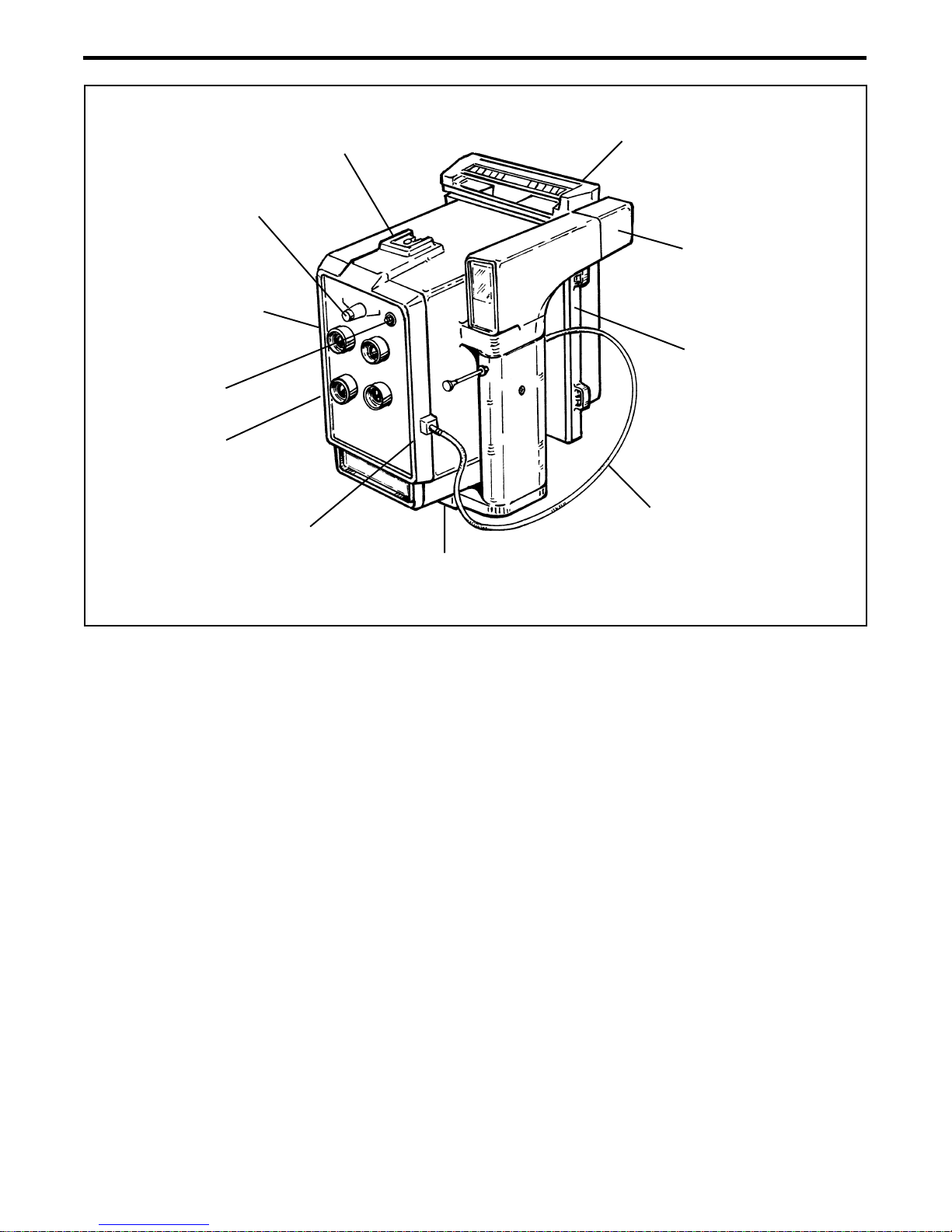
The M402b MiniPortrait Camera (Figure 1-1) is a high quality , professional 4-lens camera for
document photography .
Figure 1-1. M402b MiniPortrait camera
Features
Table 1-1 lists and describes the camera's features (Figure 1-2).
Features Description
Tripod Mount Built into the base of the camera allowing standard
Table 1-1. Camera features
tripod adapters to be attached to it.
4
M402b MiniPortrait Camera Repair Manual Overview
Aperture Knob
Shutter
Cocking Lever
Not shown
X-sync
Connector
Lens
Hot Shoe
Shutter Button
Camera Back
Viewfinder
Camera Back
Interface Plate
Shutter
Release Cable
Tripod Mount
(Not Shown)
Figure 1-2. Camera features
Table 1-1. Camera features (cont'd)
Features Description
Shutter Button Manually trips the shutter.
The shutter button doubles as a connector for
the shutter cable release.
Pressing the shutter button (or the cable release)
initiates the movement of the shutter blades as the
photograph is taken.
Shutter Release Cable Screws into the shutter allowing it to be tripped from
the hand grip.
5

M402b MiniPortrait Camera Repair Manual Overview
Table 1-1. Camera features (cont'd)
Features Description
Lens (4) Four 136 mm glass lenses allowing for four (4)
identical pictures on one piece of film.
Shutter Cocking Lever Used to latch the mechanical components of the
shutter into the proper position for taking a picture.
The shutter speed is fixed at 1/200th second.
Aperture Knob Adjusts camera exposure from f8 to f32.
Hot Shoe Illumination for the camera is supplied by an
accessory electronic flash.
The hot shoe which is located on top of the camera
provides the connection for the accessory electronic
flash.
X-sync Connector The X-sync connector, which is located on the front
cover of the camera, connects the accessory
electronic flash to the camera.
Upon tripping the shutter, the internal X-sync
connector switch , which is triggered by the action of
the mechanical shutter being tripped, fires the
accessory electronic flash.
Camera Back The camera uses Polaroid 3 1/4 x 4 1/4 peel-apart
pack films to produce color or black and white photos.
An adapted CB-103 camera back comes with the
camera. It comes with a dark slide so that camera
backs can be changed without fogging the film.
6

M402b MiniPortrait Camera Repair Manual Overview
Table 1-1. Camera features (cont'd)
Features Description
Viewfinder Used to frame the subject.
Place the subject the appropriate distance from the
shutter and then look through the viewfinder to frame
the subject.
Once the subject is framed, press the shutter button or
the shutter release cable.
Camera Back Interface Plate Allows for Interchangeable camera backs.
7

M402b MiniPortrait Camera Repair Manual Overview
Specifications
Lenses Four 136 mm (2-element) glass lenses.
Focus Optimal at 1.2 m.
Aperture f8 to f32 continuous.
Aperture Setting Turn knob to indicator .
Shutter Speed 1/200th second.
Shutter Activation Shutter button on camera or hand grip cable release.
Strobe Hot shoe accepts MP485 flash (PID 624066) or any
compatible electronic flash.
X-sync Allows for the use of professional electronic strobes.
Camera Back 3 1/4 x 4 1/4 pack film back (PID 624066).
Timer Digital LCD.
Lens Caps Four (4) provided.
Handgrip Integral side mounted.
Tripod Mount Universal
Weight 1.65 kg
Size (W x H x D) 15.25 cm x 21.5 cm x 17.75 cm
Film All Polaroid 3 1/4 x 4 1/4 color pack films, including Polaroid
Studio 125, Studio Polaroid, T669, and PC100.
All Polaroid 3 1/4 x 4 1/4 B&W films including T664 and T667.
8

M402b MiniPortrait Camera Repair Manual Disassembly/Assembly
2. Disassembly/Assembly
This section of the Repair Manual describes the camera's disassembly procedures.
CAUTION
Care should be taken throughout all disassembly and reassembly procedures
never to smudge or soil the lenses.
Required Tools and Equipment
• Lens cleaning tissue
• Dust and static free wiping cloth
• Cotton gloves or finger cots
• Standard tool kit
• Solder sucker
• Tweezers
• Hot glue gun and glue
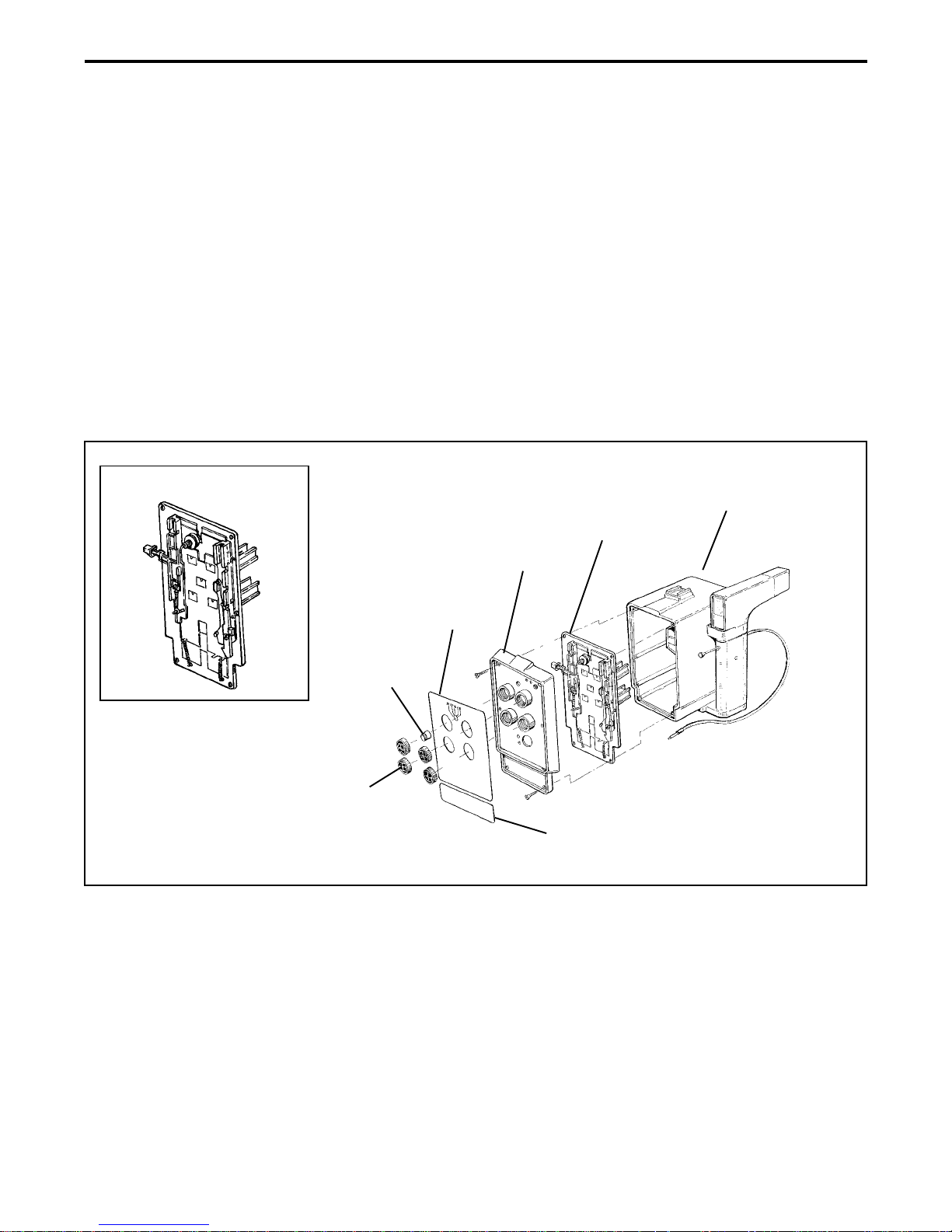
Front Cover Assembly (Figure 2-1)
Removal
1. Remove the four (4) lens caps from the front cover lenses.
2. Pull out the aperture knob from the aperture drive gear .
3. Using a pair of tweezers, peel off the upper decal cover and lower decal cover .
4. Using a Phillips head screw driver , remove the six (6) screws that secure the front cover
and the shutter plate assembly to the camera body .
CAUTION
When installing the front cover make sure:
• the four (4) fine thread screws are used to secure the top of the front
cover and the shutter plate assembly to the camera body .
• the two (2) coarse thread screws are used to secure the bottom of the
front cover and the shutter plate assembly to the camera body .
9

M402b MiniPortrait Camera Repair Manual Disassembly/Assembly
5. Gently lift off the front cover being careful not to disturb the alignment of the shutter plates.
Note: If the shutter and the diaphragm plates are misaligned during the removal
of the front cover , refer to the Shutter and Diaphragm Plate
assembly/disassembly procedure to properly realign (see page 24).
6. Disconnect the black and red X-sync connections from the shutter plate connector pins.
Rear View of Front Cover
CAUTION
When installing the front cover make sure:
• the four (4) fine thread screws are used to
secure the top of the front cover/shutter
plate assembly to the camera body.
• the two (2) coarse thread screws are used to
secure the bottom of the front cover/shutter
plate assembly to the camera body.
Figure 2-1. Removing front cover assembly
Upper Decal
Aperture Knob
Lens Cap
Cover
Front Cover
Assembly
Lower Decal
Shutter Plate
Assembly
Cover
Camera
Body
Installation
1. Connect the black and red X-sync connections from the front cover to the shutter plate
connector pins.
Note: Make sure the red and black X-sync wires are properly dressed so that they
do not interfere with the operation of the shutter.
2. Gently position the front cover onto the shutter plate being careful not to disturb the
alignment of the shutter plates.
Note: If the shutter and the diaphragm plates are misaligned during the installation
of the front cover , refer to the Shutter and Diaphragm Plate
assembly/disassembly procedure to properly realign (see page 24).
10

M402b MiniPortrait Camera Repair Manual Disassembly/Assembly
3. Using a Phillips head screw driver , install and tighten the six (6) screws that secure the
front cover and the shutter plate assembly to the camera body .
CAUTION
When installing the front cover make sure:
• the four (4) fine thread screws are used to secure the top of the front
cover and the shutter plate assembly to the camera body .
• the two (2) coarse thread screws are used to secure the bottom of the
front cover and the shutter plate assembly to the camera body .
4. Install a new upper decal cover and lower decal cover making sure that they are properly
positioned on the front cover.
5. Install the aperture knob to the aperture drive gear.
Note: If necessary, recalibrate the camera as explained in Section 3 of
this Repair Manual.
6. Install the four (4) lens caps to the front cover lenses.
11
M402b MiniPortrait Camera Repair Manual Disassembly/Assembly
Shutter Plate Assembly (Figure 2-2)
Removal
1. Remove the front cover assembly (Figure 2-1).
2. Gently lift off the shutter plate assembly being careful not to disturb the alignment of the
shutter plates.
Note: If the shutter and the diaphragm plates are misaligned during the removal
of the shutter plate assembly , refer to the Shutter and Diaphragm Plate
assembly/disassembly procedure to properly realign (see page 24).
3. Disconnect the black and red X-sync connections from the shutter plate connector pins.
Shutter Plate Assembly
Shutter Plate
Assembly
Front Cover
Assembly
Upper Decal
Cover
Aperture Knob
Lens Cap
Lower Decal
Cover
Figure 2-2. Removing shutter plate assembly
Camera
Body
Installation
1. Connect the black and red X-sync connections from the camera body to the shutter plate
connector pins.
Note: Make sure the red and black X-sync wires are properly dressed so that they
do not interfere with the operation of the shutter.
12

M402b MiniPortrait Camera Repair Manual Disassembly/Assembly
2. Gently position the shutter plate assembly onto the camera body being careful not to
disturb the alignment of the shutter plates.
Note: If the shutter and the diaphragm plates are misaligned during the installation
of the shutter plate assembly , refer to the Shutter and Diaphragm Plate
assembly/disassembly procedure to properly realign (see page 24).
3. Install the front cover assembly (Figure 2-1).
13
 Loading...