

Page 1

HD-Ready Widescreen LCD TV with Digital Tuner
Page 2

This product contains electrical or electronic materials. The presence of these materials may,
if not disposed of properly, have potential adverse effects on the environment and human
health. Presence of this label on the product means it should not be disposed of as unsorted
waste and must be collected separately. As a consumer, you are responsible for ensuring that
this product is disposed of properly. To fi nd out how to properly dispose of this product, please
go to www.polaroid.com and click on “Company“ or call the customer service number for your
country listed in the instruction manual.
This TV incorporates High-Defi nition Multimedia Interface (HDMITM) technology.
HDMI, the HDMI logo and High-Defi nition Multimedia Interface are trademarks or registered
trademarks of HDMI Licensing LLC.
Page 3

FCC
Federal Communications
Commission Statement
This equipment has been tested and found to comply with the limits of a class B digital device,
pursuant to Part 15 of the FCC Rules. These limits are designed to provide reasonable protection
against harmful interference in a residential installation. This equipment generates, uses and can
radiate radio frequency energy and, if not installed and used in accordance with the instructions, may
cause harmful interference to radio communications. However, there is no guarantee that
interference will not occur in a particular installation. If this equipment does cause harmful
interference to radio or television reception, which can be determined by turning the equipment off
and on, the user is encouraged to try to correct the interference by one or more of the following
measures:
1. Reorient/Relocate the receiving antenna.
2. Increase the separation between the equipment and receiver.
3. Connect the equipment into an outlet on a circuit which is different from what the receiver is
connected to.
4. Consult the dealer or an experienced radio/TV technician for help.
Changes or modi cations not expressly approved by the manufacturer
responsible for compliance could void the user authority to operate the
equipment.
ENGLISHENGLISH
1
Page 4
Warnings and Precautions
Warnings and Precautions
To prevent any injuries, the following safety precautions should be observed in the installation, use,
servicing and maintenance of this equipment.
Before operating this equipment, please read this manual completely, and keep it nearby for future
reference.
This symbol is intended to alert the user to avoid the risk of electric shock.
WARNING
CAUTION
This equipment must not be disassembled by anyone except qualifi ed service personnel.
This symbol is intended to alert the user to the presence of important operating and
maintenance instructions in the literature accompanying the appliance.
To reduce the risk of fi re or electric shock, do not expose this equipment to rain or moisture.
▪ TO REDUCE THE RISK OF ELECTRIC SHOCK,
▪ DO NOT REMOVE COVER (OR BACK).
▪ NO USER-SERVICEABLE PARTS INSIDE.
▪ REFER SERVICING TO QUALIFIED SERVICE PERSONNEL.
Use of controls, adjustments or performance of procedures other than those specifi ed herein
may result in hazardous radiation exposure.
Important Safety Instructions
This symbol indicates caution points.
This symbol indicates actions that should not be done.
This symbol indicates actions that must be performed.
▪ Do not place the equipment on any uneven or unstable carts, stands, tables, shelves etc.
The equipment may fall, causing serious injury to children or adults and serious damage to
the equipment itself.
▪ Use only a cart or stand recommended by the manufacturer. This equipment and
recommended cart or stand should be handled with care. Quick stops, excessive force, and
uneven surfaces may cause the equipment and cart/stand to overturn.
▪ Do not disable the 3-wire grounding type plug. The grounding pin on the 3-prong plug is an
important feature. Removing the grounding pin will increase the risk of damaging the
equipment.
▪ If you can not fi t the plug into the electrical outlet, contact an electrician to install a grounding
outlet.
▪ Always operate this equipment from the type of power source indicated on the rear of the
serial/model plate.
▪ Never overload wall outlets and extensions.
2
Page 5
Warnings and Precautions
▪ Use and handle the power cord with care. Do not place any heavy objects on the AC
power cord.
▪ Do not pull the AC power cord. Do not handle the AC power cord with a wet hand.
▪ Do not touch the power cord and antenna cable during lightning.
▪ Remove the plug from the wall outlet, if the equipment will not be used for a long period
of time.
▪ Do not place, use or handle this equipment near water.
▪ Never expose the equipment to liquid, rain, or moisture.
Seek for service if any of the above is spilled into the equipment.
▪ Do not expose the equipment to extreme temperature or to direct sunlight, as the
equipment may heat up and suffer damage.
▪ Do not install the equipment near any heat sources such as radiators, heat registers,
stoves, or any other apparatus that might produce heat.
▪ Do not attempt to service the equipment yourself.
▪ Opening and removing the covers may expose you to dangerous voltage or other
hazards and may void your warranty. Refer service to qualifi ed personnel.
▪ Do not place or drop any other objects on top.
▪ Do not insert anything into the ventilation holes of your equipment.
Inserting any metal or fl ammable objects may result to fi re or electric shock.
▪ Protect the power cord from being walked on or pinchrd particularly at plugs ,convenience
receptacles, and the point where they exit from the apparatus.
▪ Do not place the equipment on uneven or unstable carts, stands, tables, shelves etc. The
equipment may fall, causing serious injury to children or adults and serious damage to
the equipment itself.
Always place the equipment on the fl oor or on a surface that is sturdy, level, stable and
strong enough to support the weight of the equipment.
▪ Do not block any ventilating openings. Leave an open space around the equipment.
Never place the equipment :
on a bed, sofa, rug, or any other similar surfaces; too close to drapes/curtains/walls, in a
bookcase, built-in cabinet, or any other similar places that may cause poor ventilation.
▪ Unplug this apparatus during lightning storms or when unused for long periods of time.
▪ Refer all servicing to qualified service personnel. Servicing is required when the
apparatus has been damaged in any way, such as power-supply cord or plug is
damaged, liquid has been spilled or objects have fallen into the apparatus, the apparatus
has been exposed to rain or moisture, does not operate normally, or has been dropped.
▪ Always remove the power cord from the outlet before cleaning the equipment.
▪ Never use liquid or aerosol cleaners on the equipment.
Clean only with a soft dry cloth.
ENGLISHENGLISH
▪ Only use attachments/accessories specified by the manufacturer.
3
Page 6
Warnings and Precautions
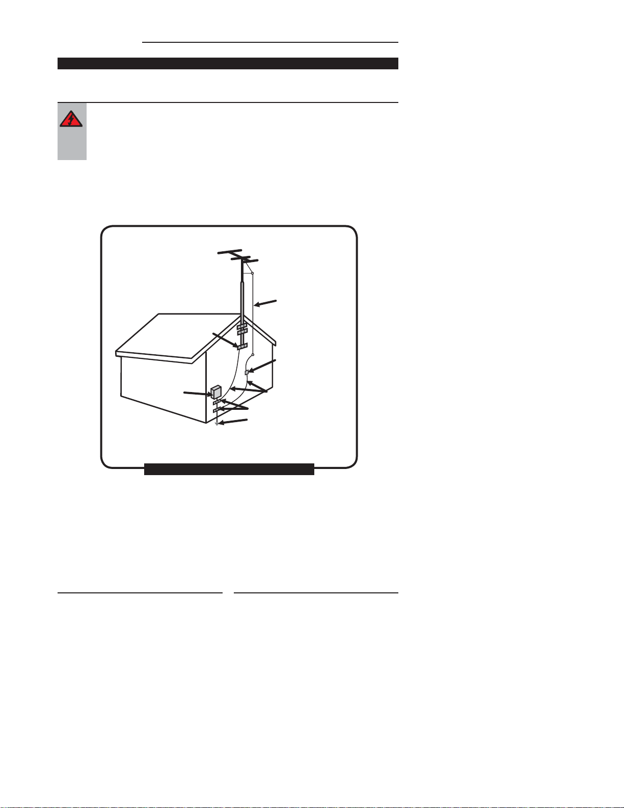
Outdoor Antenna Safety Instructions
If an outdoor antenna is connected, follow the precautions below:
▪ An outdoor antenna should not be located in any area where it could come in contact with
overhead power lines, or any other electric light or power circuits.
▪ When installing an outdoor antenna system, extreme caution should be taken to prevent
contact with power lines. Direct contact with power lines may be fatal and should be avoided
at all costs.
Section 810 of National Electrical Code (NEC) provides information with respect to proper grounding of the
mast and supporting structure, grounding of the lead-in wire to an antenna discharge unit, size of grounding
conductors, location of antenna discharge unit, connection to grounding electrodes, and requirements for
the grounding electrode.
Antenna lead-in wire
Ground clamps
Electric service
equipment
EXAMPLE OF OUTDOOR ANTENNA GROUNDING
Ground clamps
Power service grounding
(NEC Art250 part H)
NEC : National Electrical code
4
Antenna discharge unit
(NEC section 810-20)
Grounding conductors
(NEC section 810-20)
Page 7

TABLE OF CONTENTS
Preparation
Important Safety Instructions .............................................................................. 1
Antenna Safety Instructions .................................................................................4
Chapter 1 Introducing the LCD TV
Package Contents..................................................................................................6
Setting Your LCD TV............................................................................................... 7
Your LCD TV..............................................................................................................8
Remote Control.......................................................................................................11
Chapter 2 Installing the LCD TV
Connecting a TV Cable or Aerial...........................................................................14
Connecting a DVD Player .............................................................. .......................17
Connecting a VCR & Video Camera....................................................................18
Connecting a TV box and satellite Receiver ......................................................19
Connecting an Audio Receiver ............................................................................20
Chapter 3 Using The Features
Basic Operation......................................................................................................21
OSD Menu Operation.......................................................................................... 22
The Video Settings.................................................................................................23
The Audio Settings.................................................................................................23
The Setup Settings.................................................................................................24
The Parantal Settings............................................................................................ 25
The Screen Settings...............................................................................................25
Using The DVD Features.......................................................................................26
ENGLISHENGLISH
Troubleshooting
..............................................................................................................35
Specifications..................................................................................................................37
5
Page 8

Chapter 1 Introducing the LCD TV
Package Contents
Make sure all of the following contents are included.
LCD TV
VIDEO Cable Remote Control/
Component Cable
AAA Batteries x 2
POWER
CHLIST
SUBTITLE
GUIDE
SLEEP
ATVDT V
VOL CH
INPUT
MENU
EXIT
OK
INFO PMODE
Power Cord
User’s Manual
AUDIO Cable Warranty Card
Quick Start Guide
These items are all you need to set up and operate the LCD TV in its basic confi guration.
Make sure all of the above contents are included in the package. If you are missing
any items, please contact the Polaroid customer service department.
6
Page 9
Setting Up Your LCD TV
Chapter 1 Introducing the LCD TV
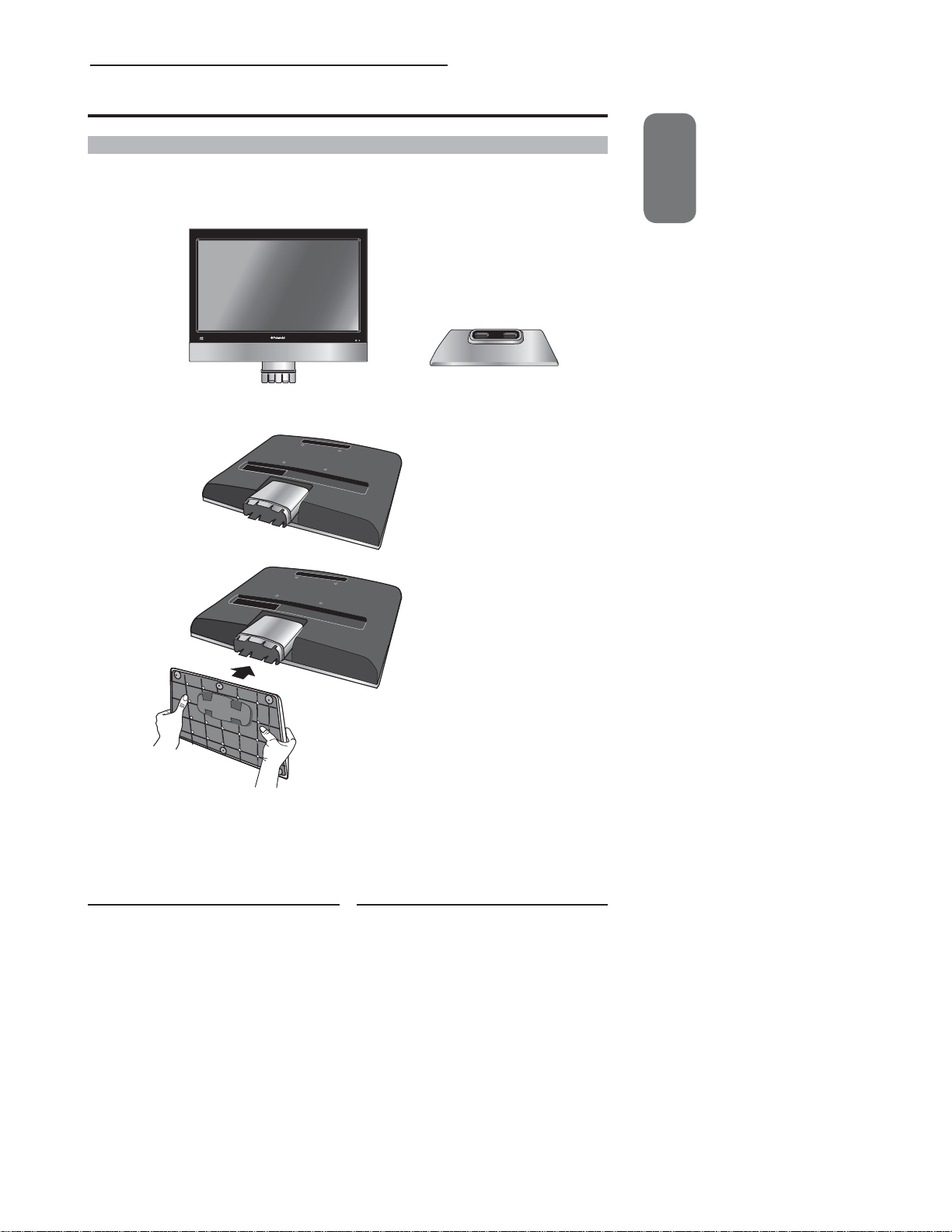
How to install the TV Stand
Follow the instructions below to install the TV stand:
Open the box, and make sure all necessary parts are in the box. The package
contains:
LCD TV
Stand
Cover an even stable surface with a soft cloth. Place the LCD TV unit face-
down on the cloth. Fit the stand onto the bottom of the LCD TV unit as shown:
Then push until the stand clicks into the LCD TV’s stand socket.
ENGLISH
To Remove the LCD TV’s stand socket for wall mounting:
Ensure the stand base is removed. For wall mounting the stand socket attached to the back of the TV
should be detached. Using a Phillips screwdriver remove the screw which is inside the stand socket. The
stand socket section should then slide off the locator rod connected to the TV.
To attach this LCD TV to a wall a standard 100x100 VESA mounting bracket is required.
7
Page 10

Chapter 1 Introducing the LCD TV
How to setup the TV
Use a supplied antenna cable to connect the VHF/UHF signal to the LCD TV’s ANT. terminal
(refer to page 15-18).
Connect the AC power cord at the back of the TV and connect the power cord to wall outlet.
Insert the 2 batteries supplied in remote control.
Step1 Slide the back cover up to open the
battery compartment of the remote
control.
Step2 Insert two AAA size batteries.
Make sure to match the (+) and
( - ) ends of the batteries with
the (+) and ( - ) ends indicated
in the battery compartment.
Slide the cover back into place.
Do not use caustic cleaners (porcelain, stainless steel, toilet, or oven cleaner
etc.) on the remote, as it may su er damage.
Connect other an external AV device (refer to page 19-25).
8
Page 11
Your LCD TV
Chapter 1 Introducing the LCD TV
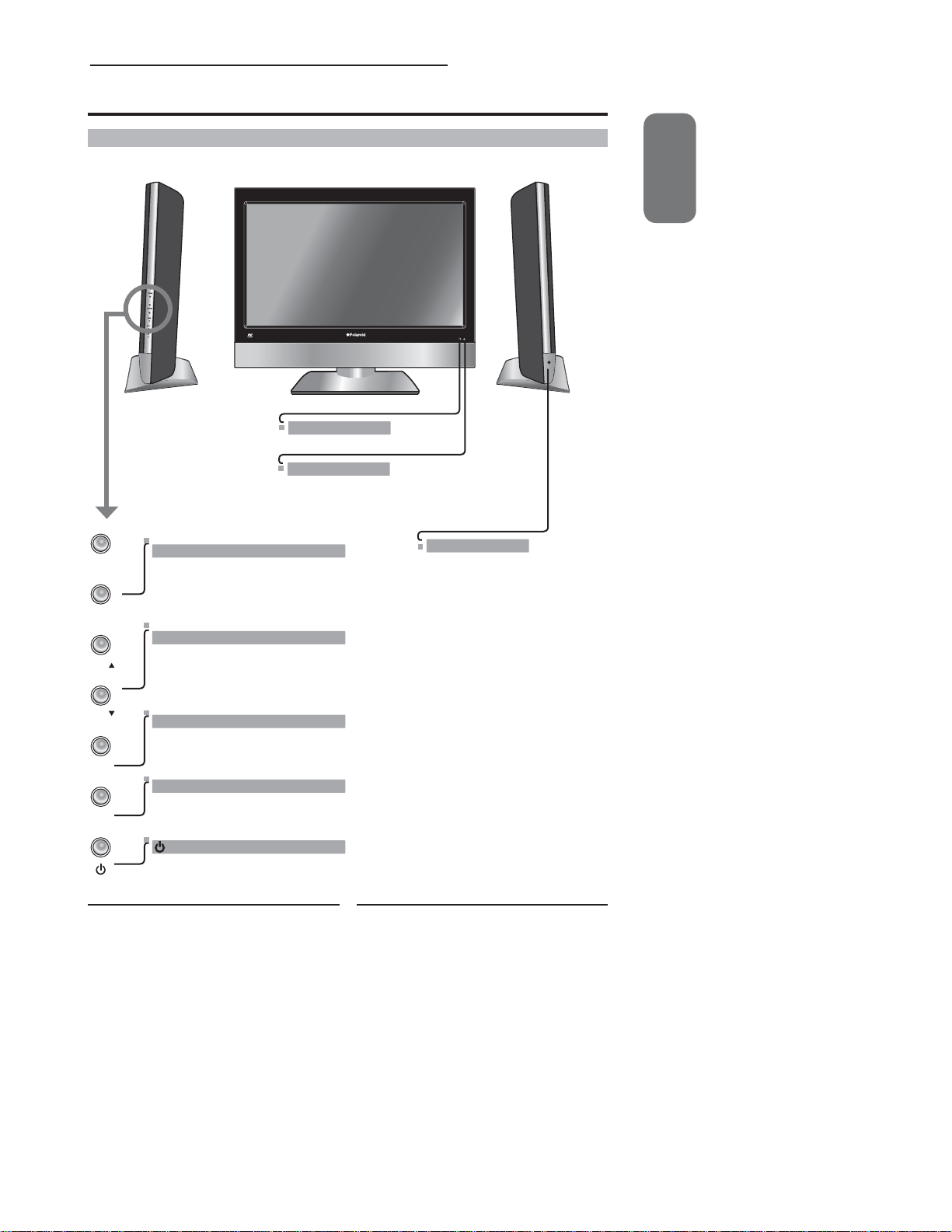
Front/Left /Right Side View and Controls
VOLUME
+-
VOL.+
Adjusts the volume up and down.
Selects the main-menu item and change
values for items when in the OSD mode.
VOL.-
CHANNEL▲▼
Scans up and down through channels.
CH.
Selects sub-menu item when in the OSD
mode.
Front View
IR
Infrared Receiver
LED
The LED light indicates when the
LCD TV is activated.
HEADPHONE
Connects to the external
headphone for private listening.
ENGLISH
Left Side ViewRight Side View
CH.
MENU
INPUT
MENU
Press once to display the OSD (on screen
display), press again to turn the OSD off.
INPUT
Chooses from different input signal sources.
Turns the LCD TV on and into standby mode.
9
Page 12
Chapter 1 Introducing the LCD TV
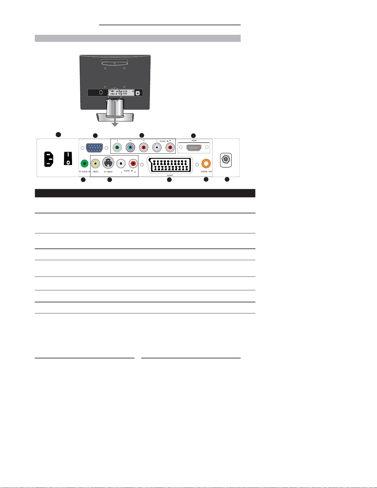
Rear View and Jacks
1
6
PC/VGA IN
34 2
ITEM DESCRIPTION
1 AC IN / Power Switch
2 AV1
SCART
3 AV2
S-VIDEO/AUDIO
(L/R)
4 AV3
VIDEO/AUDIO(L/R)
5 AV4
Y, Pb, Pr /AUDIO(L /R)
6 AV5
PC/VGA I N/PC AUDIO IN
7 AV6
HDMI IN
8 DIGITAL OUT
9 VHF/UHF IN
Connect s the AC power cord to this socket. / Make sure
that this switch is in t he ON position (Red LED light wi ll
show on the bot tom centre of the TV).
Connect to ex ternal equipment with s cart socket. This
scart inpu t allows audio and CVBS/ YC/RGB +CVBS.
RGB,S-V IDEO from an external dev ise to be shown on
your TV.
Connect s to the S- VIDEO output sock ets and Audio
output sockets on your video equipment.
Connect s to the composite A/V out put sockets on your
video equipment.
Connect s to the component (Y, Pb, Pr) video socket s
and audio (L/ R) sockets of your DVD player, HDTV, or
video equipment.
Connect s to a PC or other devices with a VGA inter face.
Connects to d evices with a HDMI interfa ce.
Connects to digital out socket on external digital
audioequipment.
Connect s RF input from VHF/UHF antenna or c able to receive high/standa rd
de nition television.
5
7
VHF/UHF IN
8
9
10
Page 13

Your Remote Control
1
POWER
Turns the LCD TV on and into standby mode .
2
Mutes and restores your LCD TV sound.
ATV /DT V
3
Pressing enter ATV (analogue) or Digital (DTV)
Mode.
4
0-9
Select and switch to a channel by
using 0-9 buttons.
5
GUIDE
In DTV mode,pressing GUIDE key displays
the electronic program guide on the screen.
6
CH. +/-
Changes the channels up and down .
VOL. +/-
7
Increases and decreases volume.
SLEEP
8
Sets the LCD TV sleep time.
- Press the SLEEP button to select the number of
minutes. followed by 15, 30, 60minutes and o .
The timer begins to count down from the
number
of minutes selected.
a.To check the remaining sleep time, press the
SLEEP button once.
b.To cancel the sleep time, repeatedly press the
SLEEP button until the display o appears.
c. If you turn the set o after setting the sleep
timer, the setting will be erased.
9
CH. LIST
Display all channel list & name.
SUBTITLE
Press the SUBTITLE key to display the subtitle
which is broadcast with the program on the
screen.
10
Turns on and o the Teletext function.
I-II
11
Cycles through the TV Sound options:
MONO/DUAL/STEREO.
Chapter 1 Introducing the LCD TV
11
2
4
5
3
7
GUIDE
VOL CH
EXIT
POWER
CH LIST
SUBTITLE
SLEEP
ATV DTV
INPUT
MENU
13
OK
INFO P MODE
12
P. M O D E
Selects picture mode: Custom, Vivid,
Standard, Mild.
13
EXIT
Exits the OSD menu (on-screen display).
ENGLISH
1
9
10
8
6
12
11
Page 14

Chapter 2 Installing the LCD TV
14
15
▲▼◄ ►
INFO
16
OK
Pressing once displays a variety of information such
as the current channel and the input source.
17
INPUT
Cycles among the di erent input signal INPUT:
TV AV1(SCART) AV2(S-VIDEO) AV3(CVBS) AV4(Y Pb Pr) AV5(VGA) AV6(HDMI) DTV
18
29
Accesses the TELE TEXT items or corresp onding pages.
The coloure d buttons are used to access inter active modes
when using Dig ital / Freeview TV channe ls.
POWER
CH LIST
SUBTITLE
GUIDE
VOL CH
EXIT
INFO P MODE
SLEEP
ATV DT V
INPUT
MENU
OK
14
12
Page 15

Chapter 2 Installing the LCD TV
Chapter 2
Installing the LCD TV
Refer to the owner’s manual of any external equipment to be connected.
When connecting any external equipment, do not connect any AC power cords to wall outlets
until all other connections are completed.
Connecting a TV Cable or an Antenna
Antenna Connection
The antenna requirements for good color TV reception are more important than those for a black &
white TV reception. For this reason, a good quality outdoor antenna is strongly recommended.
The following is a brief explanation of the type of connection that is provided with the various antenna
systems.
■ A 75-ohm system is generally a round cable (not included) with F-
type connector that can easily be attached to a terminal without
tools.
F-type connector
75-ohm coaxial cable (round)
■ A 300- ohm system is a at twin-lead cable (not included) that can
be attached to a 75-ohm terminal through a 300 -75-ohm adapter
(not included).
ENGLISH
300-ohm twin-lead cable ( at)
13
Page 16

Chapter 2 Installing the LCD TV
Use one of the following two diagrams when connecting an outdoor antenna.
A: Shows how to use a VHF/UHF combination outdoor antenna.
B: Shows how to use a separate VHF and/or UHF outdoor antenna.
A. Combination VHF/UHF antenna
VHF/UHF
Antenna
300-ohm twinlead cable
300/75-ohm adapter
(not included)
B. Separate VHF and/or UHF antennas
75-ohm
coaxial cable
VHF/UHF
Antenna
14
Combiner
(not included)
IN
OUT
300-ohm twinlead cable
75-ohm
coaxial cable
300-ohm twinlead cable
UHF
Antenna
VHF
Antenna
Page 17

Chapter 2 Installing the LCD TV
Cable TV (CATV) Connection
This reminder is provided to call the CATV system installer’s attention to Article 820-40 of the
National Electrical Code (NEC) that provides guidelines for proper grounding and, in particular,
specifi es that the cable ground shall be connected to the grounding system of the building
accurately, or as close to the point of cable entry as possible. Use of this TV for other than
private viewing of programs broadcasted on UHF, VHF or transmitted by cable companies for
the use of the general public may require authorization from the broadcast/cable company, and/
or program owner.
■ A 75-ohm coaxial cable connector is built into the set for easy hookup.
When connecting the 75-ohm coaxial cable to the set, connect the 75-ohm cable
into the ANT. terminal.
■ Some cable TV companies o er premium pay channels. Since the signals of these
premium pay channels are scrambled, a cable T V converter/descrambler is
generally provided to the subscriber by the cable TV company.
This converter/descrambler is necessary for normal viewing of scrambled channels.
(Set your TV to channel 3 or 4, typically one of these channels is used. If this is unknown,
consult your cable TV company.)
For more specifi c instructions on installing cable TV, consult your cable TV company.
One possible method of connecting the converter/descrambler provided by your cable TV
company is shown in the diagram below.
RF switch
(not included)
2 set signal
splitter
(not included)
Cable TV Line
OUT
A
IN
B
ENGLISH
Cable TV converter/
descrambler
VHF/UHF IN
(not included)
■ The RF switch (not included) is required to provide two inputs (A and B). Setting the RF
switch to position A allows viewing of all unscrambled channels by using the TV channel
keys.
■ Setting the RF switch to position B allows viewing of all scrambled channels via
the converter/descrambler by using the converter channel keys.
15
Page 18

Chapter 2 Installing the LCD TV
Use a supplied antenna cable to connect the TV signal to the LCD TV’s TV CABLE terminal.
1
VHF/UHF IN
Connect the AC power cord at the back of the TV and connect the power cord to wall outlet.
2
Press the POWER button on your remote to turn on your LCD TV.
3
a. After connecting an aerial to your LCD TV and connecting the mains cable to the
TV and 230VAC mains socket, turn the POWER SWITCH of rear TV on, a red light
will show on the front centre panel of the TV.
b. Press the POWER button, the red light will change to green and the First Time
Installation screen will show:
1. Make sure an aerial is fi tted then press OK button on the remote to start
the Auto Programme Scan (APS).
2. In a short while you will see the TV programmes briefl y as each channel is
received and stored in the memory. When APS is completed BBC1 will show,
press CH+/- buttons to view the other channels stored.
c. To power off press the POWER button, the green light will change to red.
Press the SOURCE button and choose TV or DTV mode then press OK to select.
4
16
Page 19

Connecting a DVD Player
Chapter 2 Installing the LCD TV
Rear of TV
PC/VGA IN
Audi
o
Audio
V
ideo
(L)
(R)
Video/AudioCable
DVD PLAYER
METHOD A (AV4 )
Use a Componen t cable to connect the (Y Pb Pr ) s ockets on the DVD player to
your LCD TV.
Use an audio cab le to connect the DVD’s audio so ckets to your LCD TV.
METHOD B (AV2)
Use an Audio cable to connect the DVD’s audio out put sockets to your LCD TV.
Use a S-Vide o cable to connect your LCD T V and DVD player.
ENGLISH
VHF/UHF IN
P
r
Pb
A
D
METHOD C (AV3)
Use an A/ V cable to connect the DVD’s comp osite output sockets to your LCD TV.
METHOD D (AV1)
Use a SCART cab le to connect the DVD’s SCART s ocket to the LCD TV’s SCART so cket.
Connect al l power INPUTs before turning on t he power switch of the LCD TV
or other conne cted equipments.
Press the POWER but ton to turn on your LCD TV.
To watch DVD, press the INPUT bu tton to select AV1,AV2, AV3,AV4.
17
Page 20

Chapter 2 Installing the LCD TV
Connecting a VCR&Video Camera
PC/VGA IN
Rear of TV
o
Audi
Audio
ideo
V
(L)
(R)
Video/Audio Cabl e
METHOD A (AV2)
Use an Audio cabl e to connect the VCR’s/ the Vide o Camera’s audio output so ckets to
your LCD TV.
Use a S-Vide o cable to connect your LCD T V and VCR player/ video camera.
METHOD B (AV3)
Use an A/ V cable to connect the VCR’s/ vi deo camera’s composite outp ut sockets
to your LCD TV.
METHOD C (AV1)
Use a SCART cab le to connect the VCR’s SCART so cket to the LCD TV ‘s SCART socket .
Connect al l power INPUTs before turning on t he power switch of the LCD TV
or other conne cted equipments.
VHF/UHF IN
Press the POWER but ton to turn on your LCD TV.
To watch video camera , press the INPUT button to se lect AV2 or AV3.
To watch VCR, press the INPU T button to select AV1, AV2 or AV3 .
5
“Not all came ras have the ability to connec t to a TV. Please check your vide o camera
user guide for compatibility”.
18
Page 21

Connecting a TV Cable Box or Satellite Receiver
Chapter 2 Installing the LCD TV
Rear of TV
PC/VGA IN
o
Audi
Audio
V
ideo
(L)
(R)
Video/AudioCable
Satellite antenna
cable
Method A(AV4) :
Use a Component c able to connect the Y/Pb/Pr socket s on the TV Cable Box to your
LCD TV.
Use an Audio cabl e to connect TV cabl e box’s audio output sockets to LCD T V.
Method B(AV2) :
Use an Audio cabl e to connect the TV Cabl e Box’s audio output socket s to your LCD TV.
Use a S-Vide o cable to connect your LCD T V and TV Cable Box.
Method C(AV3) :
Use an AV cable to connec t the TV Cable Box’s comp osite output sockets to your LCD T V.
SATELLITE RECEIVER
V
D
GACABLE
P
Pb
A
E
TV CABLE BOX
TV CABEL BOX
ENGLISH
VHF/UHF IN
r
F
HDMICABLE
Method D(AV5) :
Use a VGA 15 pins cable to conne ct the TV Cable Box ’s RGB outp ut sockets to your LCD TV.
Use a 3.5mm socket to R CA adapter cable for conne cting audio.
Method E(AV1) :
Use a SCART cab le to connect the TV Cab le Box’s SCART socket to the LCD T V’s SCART
socket.
Method F(AV6) :
Use a HDMI cable to co nnect the Satellite Rece iver HDMI connector to your LCD T V
Connect al l power INPUTs before turning on t he power switch of the LCD TV or
other connected equipments.
Press the POWER but ton to turn on your LCD TV.
To watch TV cable box , press the INPUT button to s elect AV1, AV2, AV3, AV4 ,AV5.
5
To watch programs satell ite receiver, press the INPUT but ton repeatedly to selec t AV6 .
6
19
.
Page 22

Chapter 2 Installing the LCD TV
Connecting an Audio Receiver
Rear of TV
PC/VGA IN
VHF/UHF IN
Use an audio cab le to connect the audio receiver’s audio LI NE IN sockets to LCD TV ‘s
DIGITAL OUT sockets.
Connect al l power INPUTs before turning on t he power switch of the LCD TV
or other conne cted equipments.
Press the POWER but ton to turn on your LCD TV.
20
Page 23

Chapter 3
USING THE FEATURES
Tuning in the TV channels
After conne cting an aerial to your LCD TV an d connecting the mains cab le to the TV and
230VAC mains socket, turn the POWER SWITCH of rear TV on, a red light will show on the
front centre panel of the TV.
Press the POWER button, the re d light will change to green and the First Tim e Installation
screen will show :
1. Make sure an aerial is tted th en press OK button on the re mote to start the Auto
Programme Sc an (APS).
2.In a shor t while you will see the T V programmes brie y as each channe l is received and
stored in the memory. When APS is completed BBC1 digital T V will show, press CH+/ buttons to vi ew the other channels store d.When nished ATV scan.TV will Auto change to DT V
do the rst installation channel. To view analogue T V press INPUT button and
use the up / down arrow buttons to select T V and then Press the OK but ton.Change
channels by pressing the CH +/- butto ns.
To power o press the POWER button, the green light will change to red.
Selecting a INPUT
Press the INPUT button to display the function required (T V/AV).Using the arrow buttons
on the remote highlight the function required and press the OK button to select the function.
Select T V Channel
Press the CH.+/- button on the remote control and the CH.+/-button on the LCD TV to change
the TV channels.
You can directly select the TV channel required by pressing 1,2 or 3 etc on the remote
button pad.
Adjusting the Volume
Press the VOL. +/– but ton on the remote control or the VO L. +/- button on the LCD TV to adjus t
the volume.
To Mute the Sound
Press MUTE and th e sound cuts o .
To turn mute o , press the MUTE button a gain, or simply press the VO L +/- button .
Sleep Timer
Press the SLEEP but ton continuously to select the sleep tim er or turn the sleep timer from the
OFF,15,30,60minutes; when the LCD T V has reached the set time, it will automatically turn o . If
the TV has no input signal, i t will automatically power down to standby after 15 minutes.
Chapter 3 Using the LCD TV
ENGLISH
21
Page 24

Chapter 3 Using the LCD TV
OSD Menu Operation
1 The main menu provides access to the following menus:
Video Adjust picture setting such as picture
Audio Adjust sound option and e ects.
Setup Adjust colour standard, sound standard,
Preferences Adjust preferences such as OSD, blue
Screen Adjust screen such as horizontal size, horizontal
DTV (Digital T V) The DTV menu pr ovide four submenus as follow :
2 Press the MENU button on the remote control. The main menu will appear on the screen.
3 Use
◄/► to highlight your main menu option, then press OK to enter your selected option.
Use ▲/▼
item.Press the EXIT button to exit menu.
VIDEO
Use this Video setting menu to adjust the picture quality which best corresponds to your viewing requirements.The Video
Menu includes the following options:
mode, contrast, brightness,sharpness
colour and advanced.
APS, Manual search, Channel setup.
screen, childlock, sleep timer, OSD
timer, OSD reset.
position, ver tical position, phas e, auto sync.
edit channel li st,con guration,parental control,
EPG (Electroni c Programme Guide),with which
you can set the DT V as you wish.
to highlight an option of the sub-menu. Use ◄/► to change the value of the
OPTION DESCRIPTION
Picture Mo de
Contrast
Brightness
Colour
Tint(NTSC)
Sharpness
Custom:Select for user’s settings.
The items of video can be adjusted when the
picture mode is for user’s settings except
advanced item.
Vivid:Select for enhanced picture contrast and
sharpness.
Standard:Select for standard picture settings.
Recommended for home entertainment
Mild:Select for mild picture settings.
Adjust the di erence between the
brightness and darkness regions of the picture.
Adjust to increase or decrease the brightness.
Allows to adjust the colour from 0 to 100.
Allows you to adjust the color tint of the
picture.(Only for NTSC)
Adjust to sharpen or soften the picture.
.
22
Page 25

The VIDEO Settings
Chapter 3 Using the LCD TV
OPTION DESCRIPTION
Ad va nc ed Di sp la y M od e Al lo ws yo u to s el ec t
AUDIO
Use this AUDIO setting menu to adjust the sound and balance and volume to your listening requirements.
the display mod e to
be Wide, 4:3,Ori ginal,
Zoom.
DCE Allow s you to adjust the
Blue
Stretch
Green
Stretch
Color
Tem p.
(Dynamic Contrast Enhancemen)
to be o , low, mid, high.
Allows you to adjust th e blue
stretch.
Allows you to adjust th e green
stretch.
Allows you to adjust t he color
temp. to be cool, war m ,
standard.
OPTION DESCRIPTION
Volume presets the vo lume to a given setting.
Balance Adjust to emphasize l eft or right speaker bal ance.
ENGLISH
23
Page 26

Chapter 3 Using the LCD TV
The Setup Settings(Analogue TV)
Setup menu is only available when viewing Analogue TV. Use this Setup menu to select Colour Standard, Sound
Standard, APS, Manual Search, Channel Setup.Use the Up/Down arrow buttons to highlight the required setting.
Press the Press OK button to select the function. Use left / right arrow buttons to adjust the settings. Press OK to
save the adjustment.
OPTION DESCRIPTION
Setup
APS
Manual Search
Channel Setup
Colour Standard Allows you to select the colour standard :
Sound Standard Allows you to select the sound standard : DK, BG,
AUTO,PAL, SECAM, UK = PAL.
I, L/L’.
DK PAL D/K, SECAM D/K (East Europe /
BG PAL B/G, SECAM B/G (Europe / East
I PAL I (U.K. / Ireland / Hong Kong /
L/L’ SECAM L/L’
China )
Europe / Asia / New Zealand / M.East
/ Africa /Australia)
South Africa)
Setup
Channel Setup
Finetune
Save
APS Start APS
Manual Search Allows you to adjust the manual search by hand if
Channel Setup
Press OK to start Auto Search and auto sort
process. Note: Auto Sort will only operate in UK.
Country
Allows you select the country :Austria, Belgium,
Switzerland, Czech Rep., Germany, Denmark,
Spain, France, Finland, UK, Greece, Hungary, Italy,
Norway, Netherlands, Portugal, Poland, Sweden,
Slovenia, Slovakia, Turkey, Others.
signal is too weak or picture is blurry.
Press the ►button to select Sort,
Delete, Skip, Finetune, Save.
Sort
Allows you to manually sort
the stored programme
Delete
Allows you to delete the
stored programme.
Skip
Allows you to skip the
stored programme.
Finetune
Allows you to finetune the
stored programme.
Save
Allows you to save the set-
up.
24
.
Page 27

The Preferences Settings
Chapter 3 Using the LCD TV
Use this Preferen ces setting menu to set up som e features: OSD, Blue Screen, Child lock, Sleep Timer, OSD Time r,
OSD Reset.
OPTION DESCRIPTION
OSD Language : Allows you to sel ect the OSD to
Blue Screen Allows you to sele ct the blue screen to be o
Childlock Allows you to selec t the childlock to be yes
Sleep Timer Allows you to select th e sleep timer to be o ,
OSD Timer Allows selec tion of the display time of the on -
OSD Reset
SCREEN(Only for VGA)
be English, French, Spanish, German,
Italian, Por tugese, Dutch, Poli sh .
Transparency: All ows you to adjust
transparenc y from 0 to15.
or on.
or no. (Default p assword is 0000. gold en
password is 3796.)
Change Pin: Allows you to ch ange the 4-digit
password.
15min, 30min, 60min.
screen menu:5 s,10 s,15 s, 20 s, 25 s.
Allows you to restor e the factory setti ngs
ENGLISH
.
Auto Sync.
OPTION DESCRIPTION
Horizontal
Size
Horizontal
Position
Vert ical
Position
Phase Allows you to improve fo cus clarity and
Auto Sync. Allows to auto sy nchronize VGA signal.
Allows you to adjust th e Horizontal Size from
0 to 100.
Allows you to adjust t he Horizontal Position
of the picture.
Allows you to adjus t the Vertical Position of
the picture.
image stability.
25
Page 28

Chapter 3 Using the LCD TV
Chapter 4 Using the DTV OSD Settings
OPTION DESCRIPTION
Edit Channel List Lock some channels that are not suited for
Con guration Add new channel, set audio language, subtitle
Parental Control Enable or Disable the menu protection system
EPG Electronic Program Guide
younger members of the family, skip/add the
channel list as you wish
language, as you wish. Upgrade the system. View
the signal information.
and allows the PIN code to be changed.
EDIT CHANNEL LIST
Highlight the Edit Channel List option, then press OK button,there are three Items in the menu.
.
Channel List
Cre ate a favo u r ite list
Modifty a fa v ou r ite list
Delete a fav o ur ite list
OK EXIT
CREATE A FAVOURITE LIST
Highlight the Create a favourite list item, pressing OK button, then The menu is displayed on the screen now. Once you enter the Create
a favourite list menu,a new channel list will be created,you can create four favourite lists at most.
You can lock or unlock the selected channel by pressing the RED button, pressing the BLUE button to skip or add the selected channel. If
you want to skip or add all, rst press the GREEN button, then press either the RED button to skip all, or the GREEN button to add all. A
channel selected as a locked appears in the channel list with a lock icon ( red button ) against the channel name, a channel selected as a
added appears in the channel list with a add icon ( tick ) against the channel name.
26
Page 29

Using the DTV OSD Settings
Chapter 3 Using the LCD TV
Channel List
FAV 1
1
BBC ONE
2
BBC TWO
BBC THREE
3
4
CBBC Channel
5
BBC NEWS 24
6
BBCi
Lock Skip Skip A dd AllSort Move
By pressing the YELLOW button you can sort the channels in the list. Then you can sort the channels alphabetically
by pressing the RED button or sort the channels manually by pressing the BLUE button. If you have locked several
channels, by pressing the YELLOW button, the locked channels will be placed at the bottom of the Channel list in
alphabetical sort.
Exit
Exit Screen
Channel List
FAV 1
BBC ONE
1
BBC TWO
2
BBC THREE
3
CBBC Channel
4
BBC NEWS 24
5
BBCi
6
Alphabtical
sort
When you complete the edit, press the EXIT button to quit the favourite channel list menu. The next menu will ask if
you want to save the changes you have made, using the ◄/► buttons to highlight the YES option, and press the OK
button to save the changes.
EXIT
sort
Cancel operation
MoveLock U nlock
ENGLISH
Once you lock a channel, you must enter the PIN Code that is set in the parental control menu at fi rst before the
channel is displayed.
27
Page 30

Chapter 3 Using the LCD TV
If you skip a channel, it cannot be shown in the list menu ( Press OK button will pop-up the favorite channel list menu when you watch the
digital terrestrial television ) unless you add it again. ( In the channel list menu, the skipped channel name is not shown.)
MODIFY A FAVOURITE LIST
You can modify the favourite list which you have create. The list named “TV / RADIO” is the default list, the
rest are created. Select a favourite list, then press OK button to modify the list as you do in the create a
favourite list menu.
Modifty a favouri t e list
TV RAD I O
FAV1
FAV2
OK EXIT
DELETE A FAVOURITE LIST
Using the ▲/▼ buttons to highlight the list name which you want to delete, then pressing the OK button to delete the favourite list, the
pop-up menu will ask if you con rm or cancel the delete operation.
( Note: The default favourite channel list name isn’t displayed in the list, so you can only delete the list name you created.)
Delete a favourite list
You a re going to r e m o v e t h e fa vo urite list
press OK to confirm
28
Page 31

Using the DTV OSD Settings
CONFIG URATION
Highlight the Con guration option, then press OK button to enter the selected option. The
con guration menu is displayed on the screen now.
CHANNEL INSTALLATION
Use these options If you have moved location or want to rescan for new channels. Press OK
button to display the channel installation menu.
Chapter 3 Using the LCD TV
ENGLISH
If you want TV to auto search the channels, press OK button to continue. Then you should
choose the installation type by using the ◄/► buttons and press the OK button to start the
installation process. If you choose ‘add’, the new channels will be added in the channel list. If
you choose ‘new’, the new channels will replace the previous channels in the channel list
.
29
Page 32

Chapter 3 Using the LCD TV
Using the DTV OSD Settings
If you want to install the channels by yourself, using the▲/▼buttons to highlight the channel
installation (manual) option, and press ok to install manually. First you should choose the
installation type, then you can see the following menu. Using
then the bar graphs of signal level and signal quality will indicate whether any channels are likely
to be found. You should choose the channel of which the signal quality bar is high as well, then
press OK button to scan the channels.
NEW DETECTED CHANNELS
The New Detected Channels menu shows the channels that you add in the channel list
recently. The type icon of the program is displayed against the channel name.
◄/► to cycle the channel option,
30
Page 33

Using the DTV OSD Settings
Chapter 3 Using the LCD TV
Using the ▲/▼buttons to highlight the user settings item in the con guration menu, then
press OK button to display the user settings menu.
AUDIO LANGUAGE
This function select which language soundtrack you will hear when switching to a channel
broadcasting with multiple soundtracks. Highlight the audio language line in the user settings
menu and use ◄/►buttons to cycle through the language options.
SUBTITLE LANGUAGE
This function selects the desired subtitle language whenever subtitle information is broadcast.
Highlight the subtitle language line in the user settings menu and use◄/► buttons to cycle through
the language option.
SYSTEM PARAMETERS
Using the▲/▼buttons to highlight the system parameters item in the con guration menu, then
press OK button to display the system parameters menu.
ENGLISH
SYSTEM UPGRADE
Highlight the System Upgrade item in the system parameter menu, pressing OK button to
display the System Upgrade menu. press OK button to upgrade system. If there is a new
software, the unit will upgrade itself.
31
Page 34

Chapter 3 Using the LCD TV
Using the DTV OSD Settings
SYSTEM INFORMATION
Highlight the system information item in the system parameter menu, pressing OK button to
display the system information menu. You can view the system information in this menu, however,
you can modify nothing in this menu, Pressing OK button to quit.
SIGNAL INFORMATION
Highlight the Signal information item in the con guration menu, pressing OK button to display
the Signal information menu. Cycle through the channel option by using the ◄/►buttons on the
remote control. The signal level and signal quality of the channel that o ers the upgrade
software can be observed on the two bar graphs. The bar graphs of signal quality and signal
level give a good indication of whether the selected channel is likely to be found. If the signal
quality bar is high as well then it is a digital frequency and digital channels
will probably be found.
32
Page 35

Using the DTV OSD Settings
PAR ENTAL C ONTR OL
Highlight the parental control line in the parental control menu and use◄/► buttons to cycle
through the enable and disable option. Toggle this option to enable, then the following items
can be altered.
RECEIVER LOCK
You should enter the PIN CODE before you can see the DTV program while you power on the
TV and select the DTV INPUT.
Chapter 3 Using the LCD TV
ENGLISH
CONFIGURATION MENU
If you toggle this option to YES, you must enter the PIN CODE before you can access the con guration menu.
CHANNEL LOCK
If you toggle this option to YES, the channels you locked in the edit channel list menu can’t be
displayed before you enter the PIN CODE.
MATURITY LEVEL
There are 18 levels total. If you toggle this option to a number (1-18), for example, you toggle it to 15,
that’s to say, if the channels broadcast material is not suitable for the family members who are under
15 years old , you must enter the PIN CODE before you can view them. (The maturity level information
should be broadcast with these programs.)
33
Page 36
Chapter 3 Using the LCD TV
Using the DTV OSD Settings
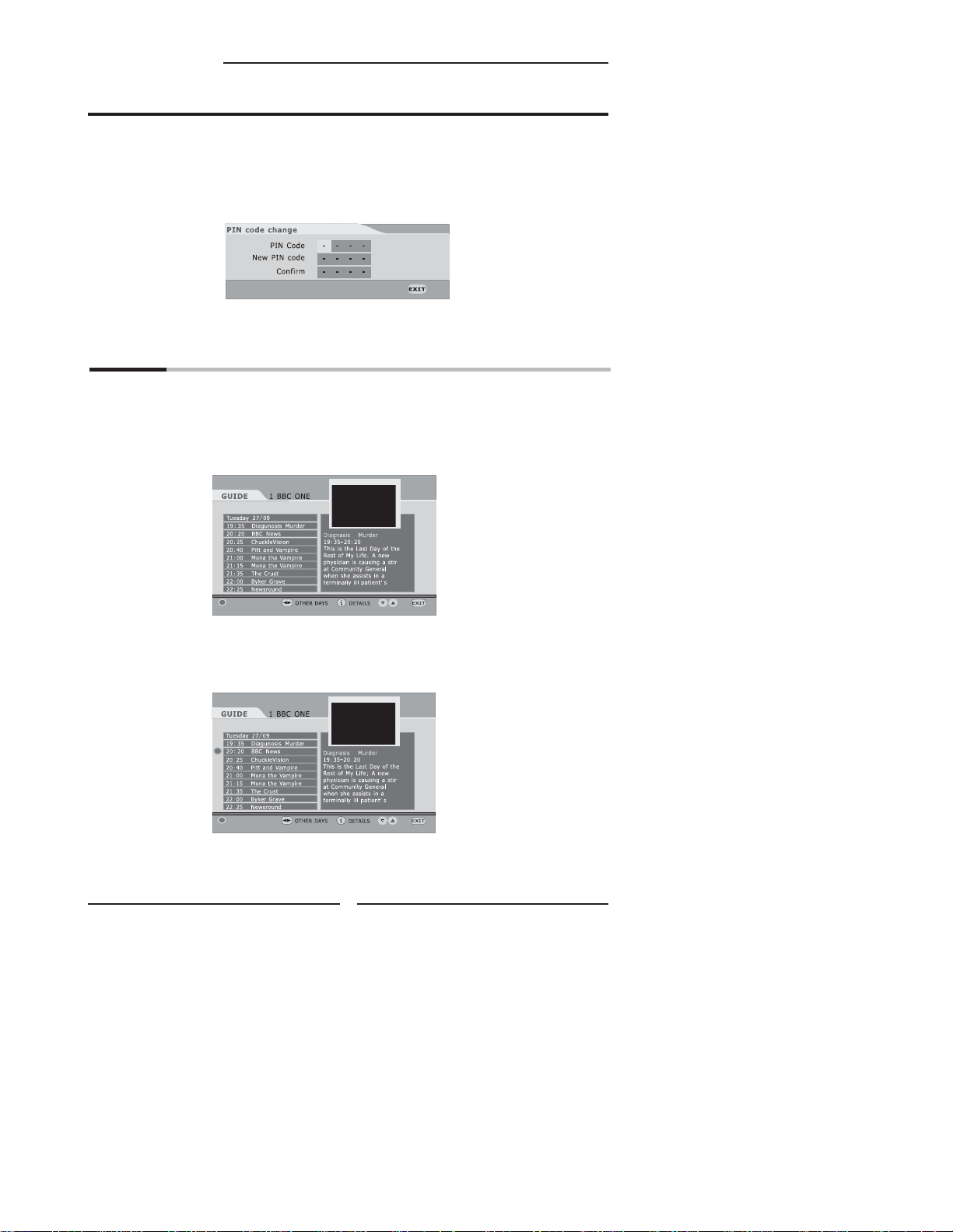
PIN CODE CHANGE
Pressing the ‘RED’ button will popup the PIN code change menu, enter the previous code by
using the 0-9 buttons on the remote control, then enter the new code twice to con rm and this
menu will disappear (The PIN is factory set to 0000). Pressing EXIT to quit without saving the
new code.
Press the OK button to quit the parental control menu and save these alterations. Press the EXIT
button to exit the parental control menu without saving these alteration.
EPG
EPG (Electronic Programme Guide) menu is reached by pressing GUIDE button, quit by
pressing GUIDE button again. Current program is highlighted. Use Channel Up/Down ▲/▼
buttons to change channels and view the other programmes on the selected channel. Press
the Arrow up / Arrow down navigation buttons to scroll through and show programme content.
There is a 7day EPG, you can see the other days channel list by using Left / right navigation
arrow ◄/► buttons.
14:58 27/09/2005
REMINDER
The short description of the highlighted channel is shown under the image window, and you
can see the extended description by pressing the INFO or OK button and by pressing this
button again you can close this window. Press “RED” button you can deminder the program
what you like it, and by pressing this button again you can cancel this reminder.
14:58 27/09/2005
REMINDER
34
Page 37

Troubleshooting
Chapter 3 Using the LCD TV
Before consulting service personnel, check the following chart for a possible cause of problem
and for a possible solution.
TV will not tu rn on
Make sure the power cord is plugged in
The batteries in the remote control may be exhausted.
Replace new and same brand batteries.
No picture, no sound
Check the interface cable between TV and antenna/cable TV.
Press the POWER button on the remote.
Press the TV button on the remote, then press INPUT button repeatedly to select the connected video INPUTs.
Poor picture, sound OK
Check the interface cable between TV and antenna/cable TV.
Try another channel, the station may have broadcast di culties.
Adjust the Brightness/Contrast options in the VIDEO Menu.
Picture OK , poor sound
Sound may be muted. Press the button on the remote.
Press the VOL+ button to increase the volume.
Audio noise
Move any infrared equipment away from the TV.
ENGLISH
35
Page 38

Speci cations
Key Features
Various Audio/Video terminals for external equipment connection
▪ 1 set of composite A/V input terminals
▪ 1 SCART input terminals
▪ 1 set of component Video input terminals
▪ 1 VGA/ Audio input terminal
▪ 1 HDMI/Auido input terminals
▪ 1 Headphone terminal
High De nition Multimedia Inter face (HDMI)
▪ High De nition Multimedia Inter face (HDMI) is a small, user-friendly interconnect that can carry up to 5
Gbps of combined video and audio in a single cable. This system eliminates the cost, complexity and
confusion of multiple cables used to connect current A/V systems.
HDTV Compon ent Video Inputs
▪ O ers the best video qualit y for DVD(480p) and digital set-top-box (HD1080i, 720p) connections.
3D Digital Noise R eduction
▪ This function can digitally reduce image noise to provide better picture quality.
WSS(Wide Screen Scale) Function
▪ This function can automatically convert and display any aspect ration (4:3 / Wide) TV
broadcast signal.
Built-in ATV and DT V Tuners
▪ The built-in DTV tuner allows the reception of DVB-T broadcasting without the addition of a set-top
box.
DISPLAY MODES
The screen resolution has been optimized during production for the display modes listed below.
If the signal from the system equals the standard signal mode, the screen adjusts automatically. If the
signal from the system is not equal to the standard signal mode, adjust the screen resolution by referring to
your video card user guide, otherwise there may be no video.
Video signal: (VGA Standard)
Resolution (Dot X Line) Vertical Frequency(Hz) Horizontal Frequency(kHz)
640 x 480 59.94 31.46
800 x 600 60.31 37.87
1024 x 768 60.00 48.36
72.80 37.86
75.00 37.50
72.18 48.07
75.00 46.87
70.06 56.47
75.02 60.0.2
36
Page 39

Speci cations
SPECIFICATIONS
MODEL
LCD Panel Panel Size 15.4” TFT LCD 19” TFT LCD
Brightness 200 300
Contrast Ratio 400:1 850:1
Max. Resolution 1280x800 1440x900
Input Connector VIDEO 1 1
S-VIDEO 1 1
YPbPr/ AUDIO IN(L/R) 1 1
AUDIO IN(L/R) 1 1
PC/VGA IN 1 1
HDMI IN 1 1
PC AUDIO IN 1 1
DIGITAL OUT 1 1
HEADPHONE 1 1
VHF/UHF IN 1 1
Power Source AC100~240V, 50/60HZ, 1.2A AC100~240V, 50/60HZ, 1.2A
Power Consumption 50 W, standby < 3 W 65 W, standby < 3 W
Dimension 15.2 w x 13.6 h x 5.2 d inch 18 w x 15.9 h x 5.2 d inch
WEIGHT 7.1 LB 12.3 LB
TLU-01541C TLU-01941C
ENGLISHENGLISHENGLISH
20070418
37
 Loading...