

Page 1

Repair Manual
Americas Business Center
Technical Services
201 Burlington Road
Bedford MA 01730
TEL: 1.781.386.5309
FAX: 1.781.386.5988
Joshua
(Vision/JoyCam/Captiva)
April 1993
Page 2

Polaroid Josh ua Camera
Service Manual
T able of Contents
1. Description ............................................................................................................... 1-1
Introduction ............................................................................................................... 1-3
Unique Joshua Differences........................................................................................ 1-2
In-Camera Picture Storage .................................................................................. 1-4
Compact Camera Size ......................................................................................... 1-5
Uniqu e M icroprocess o r Con trolled E xpo sur e Syst em.......................................... 1-7
Key Joshua Features ................................................................................................. 1-8
Us ing th e C amera ...................................................................................................... 1-10
Loading Fi lm....................................................................................................... 1-10
Erecting C amera.................................................................................................. 1-10
Taking Pi cture ..................................................................................................... 1-11
Brigh tness Adj ustment and Self- Timer ................................................................ 1-12
Major Functional Sub-Systems of the JoshuaCamera................................................ 1-13
Erecting, Viewfin der an d C amera Opt ical S yst em ............................................... 1-13
Drive an d Switc hin g S ystem................................................................................ 1-16
Shutt er S yst em .................................................................................................... 1-18
Film Frame Transp ort and Spre ading .................................................................. 1-21
Specific ation Su mmary ............................................................................................. 1-23
Camera C ompone nts , Cov ers and P ane ls ................................................................... 1-24
2. Theor y o f Operati on................................................................................................ 2-1
Seque nce o f Oper ation .............................................................................................. 2-3
Stages o f Oper ation ................................................................................................... 2-3
Loading Fil mpack into E rected or Fo lded C amera............................................... 2-3
Power ing Folde d C amera for Da rk -Sl ide when Fil mpack is Ins erted................... 2-6
Power ing Camera w hen Film Do o r is Closed , L atched and then Erected............. 2-8
Maintain ing Po wer fo r Proc ess ing after Camera is F olded................................... 2-9
Darks lide Transpo rt and Count er Wheel Indexing ............................................... 2-11
TC - 2
Page 3

Expos ing the Pi cture............................................................................................ 2-12
Blocking th e Vi ewf inder ..................................................................................... 2-13
Releasin g the Taking Mirror................................................................................ 2-14
Proce ssi ng the Ex pos ed Fra me ............................................................................ 2-16
Reseatin g the Taking Mi rro r and Op eni ng the Vi ewf ind er Blind ......................... 2-19
Special Cases............................................................................................................. 2-23
Darkslide when Film Door is Opened and Closed ............................................... 2-23
Fo lding the Camer a durin g a Proce ssi ng Cyc le.................................................... 2-24
Safety C lut ch on Feed Ro ll .................................................................................. 2-24
Syste m S chematic...................................................................................................... 2-24
3. Testing and Adjus tments ........................................................................................ 3-1
General...................................................................................................................... 3-3
Required Equipme nt ............................................................................................ 3-3
Descr iption o f E qui pment.................................................................................... 3-3
Tes ting ...................................................................................................................... 3-5
Ambient Ex posure Test ....................................................................................... 3-5
Strob e Exposure Test........................................................................................... 3-8
Adju stm ents .............................................................................................................. 3-10
Ambient Exposure Calibration ............................................................................ 3-10
Strob e Exposu re Calibr ation ................................................................................ 3-12
4. Disassembly and Reassembly.................................................................................. 4-1
Introduc ti on............................................................................................................... 4-4
Special Tools and Eq uipment Needed ....................................................................... 4-4
Disas sem bly and Assem bly Pr ocedur es ..................................................................... 4-5
Rear Panel ................................................................................................................. 4-5
Remov al .............................................................................................................. 4-5
Disa ssemb ly ........................................................................................................ 4-5
Reas sembl y ......................................................................................................... 4-7
TC - 3
Page 4

Front Panel ................................................................................................................ 4-8
Removal .............................................................................................................. 4-8
Reassembly ......................................................................................................... 4-8
Left Hand G rip and Bottom Chu te Cover .................................................................. 4-9
Remov al.............................................................................................................. 4-9
Reas s embl y ......................................................................................................... 4-9
Bottom C hu te Cov er.................................................................................................. 4-10
Disa sse mb ly ........................................................................................................ 4-10
Reas s embl y ......................................................................................................... 4-10
Right Hand Grip ........................................................................................................ 4-11
Disasse mbly ........................................................................................................ 4-11
Reassembly ......................................................................................................... 4-11
Bottom D oor A ss emb ly ............................................................................................. 4-12
Remov al.............................................................................................................. 4-12
Disa sse mb ly ........................................................................................................ 4-12
Reas s embl y ......................................................................................................... 4-15
Top Cov er ................................................................................................................. 4-16
Remov al.............................................................................................................. 4-16
Reas s embl y ......................................................................................................... 4-17
Shutt er Assemb ly ...................................................................................................... 4-18
Remov al .............................................................................................................. 4-18
Disa ssemb ly ........................................................................................................ 4-22
Reas sembl y ......................................................................................................... 4-27
Erect Syste m (V MC /Bello ws and T aking Mir ror Ca rrier A ss emblies )....................... 4-28
Disa sse mb ly ........................................................................................................ 4-28
Reas s embl y ......................................................................................................... 4-30
Main Fra me (Non -Ge ar Sid e) .................................................................................... 4-31
Disa sse mb ly ........................................................................................................ 4-31
Reas s embl y ......................................................................................................... 4-32
TC - 4
Page 5

Main Frame (Gear Side - Outer) ............................................................................... 4-33
Disassembly ........................................................................................................ 4-33
Reassembly ......................................................................................................... 4-34
Main Fra me (Gear Side - Inner) ................................................................................ 4-35
Disa sse mb ly ........................................................................................................ 4-35
Reas s embl y ......................................................................................................... 4-35
5. Troubleshooting ..................................................................................................... 5-3
Introduct ion .............................................................................................................. 5-3
Functional Test of a Joshua Camera .......................................................................... 5-5
Tools and Parts Needed for Troubleshooting ............................................................ 5-7
Common Camera Failure Modes and Corrective Procedures.................................... 5-8
Isola ting t he Pro blem ( Camera Mainf rame o r Shut ter A s sem bly?) ............................ 5-12
Appendix ................................................................................................................. A-1
Glossary of Terms to Describe the Joshua Cameras ................................................. A-2
TC - 5
Page 6

[This p age inte ntionally blank]
Page 7

1. Description
1 - 1
Page 8

1. Description
T able of Contents
Intr od uc tion........................................................................................................................... 1-3
Unique Joshua Differences.................................................................................................... 1-4
In- C amera Pict ure St orage.............................................................................................. 1-4
Compact Camera Size ..................................................................................................... 1-5
Uniqu e M icroprocess o r Con trolled E xpo sur e Syst em...................................................... 1-7
Key Joshua Features ............................................................................................................. 1-8
Us ing th e C amera .................................................................................................................. 1-10
Loading Fi lm................................................................................................................... 1-10
Erecting C amera.............................................................................................................. 1-10
Taking Pi cture ................................................................................................................. 1-11
Brigh tness Adj ustment and Self- Timer ............................................................................ 1-12
Major Function al Sub -Sy ste ms of the Jos hu a Camera ........................................................... 1-13
Erecting, Viewfin der an d C amera Opt ical S yst em ........................................................... 1-13
Drive an d Switc hin g S ystem............................................................................................ 1-16
Shutt er S yst em ................................................................................................................ 1-18
Film Frame Transp ort and Spre ading .............................................................................. 1-21
Specific ation Su mmary ......................................................................................................... 1-23
Camera C ompone nts , Cov ers and P ane ls ............................................................................... 1-24
1 - 2
Page 9

1 . Descri pti on
Introduction
The Polar oid Joshua is a com pact, fol din g, s in gle -le ns reflex c ame ra whi ch s to res it s o wn fin ish ed pic tur e s
and the darkslide. Camera operation is fully automatic and produces 10 full-color, instant Polaroid pictures
from one Joshua film pack. Picture format can be either vertical or horizontal.
The Joshua camera has an integral, fully automatic electronic flash; through-the-lens reflex viewing; and a
unique microprocessor- controlled exposure process.
Joshua Instant Color Film has an image area of 7.29 x 5.46 cm (2.87 x 2.15 inches). Each 10-exposure film
pack contains an integral, mercury-free battery for powering the Camera electronics and motor drive
systems.
Fi gure 1 -1 . J os h ua Single -Len s R eflex In s tan t Came ra
1 - 3
Page 10

Unique Joshua Differences
Three major, unique design goals have been successfully achieved in the Joshua Camera:
• Storage of finished pictures within the Camera
• Co mpa ct size with extre mely r u gged con s truction
• Improved exposure control and picture sharpness under vi r tually all lighting conditions
Each of these Joshua d ifferences will now be briefly describ ed.
In-Camera Picture Sto r age
Each film frame after exposure is picked and driven by feed rollers into a semi-circular chute chamber . . .
makes a U-turn . . . is fed into the processing rollers (spread system) . . . and picked a second time into a
storage chamber (Figure 1-2). The process is repeated for all subsequent exposures, placing all frames
(including the initial darkslide) in the camera storage chamber. The picture counter decrements one count
each time another frame is processed.
The last picture taken is visible through the storage chamber window. Finished pic tures may be removed/
replaced from the cha mber at a n y tim e.
Figure 1-2. Film frame moved through chute by feed rollers, into spread system
and finally i nto st orage cham ber on undersi d e of C ame ra
1 - 4
Page 11

Compact Camera Size
When folded, the Joshua Camera measures about 57 x 96 x 180 mm (2.25 x 3.79 x 7.1") and weighs 760
gm ( 2 7 o z) w it h a full fi lm pack.
The C ame ra is erected b y h old ing th e c amera as sh o wn an d depress ing th e R ele ase Button L atc h o n t he
Strob e Tower w ith your right thu mb (Figur e 1-3). Erecting the Camera automatically charges the Strob e,
wh en a f ilm pa ck i s i n p lac e.
F igu re 1-3. Erect ing an d C oll apsing th e C ame ra
1 - 5
Page 12

Film Loading and Picture Removal Doors provide access to the film pack compartment and the picture
chamber, respectively (Figure 1-4). Loading a film pack into the Camera and closing the Film Door brings
the pack to the image plane and automati cally transports the darkslide into the storage chamber, unless this
chamber is full. If it is, a warning LED will light and an audio signal wi ll sound, and darkslide will occur
after the picture storage chamber has been emptied.
Up to ten finished (processed) pictures may be removed and also re-inserted, if desired, in the picture
chamber, by opening the Picture Removal Door.
Figure 1-4. Access to the Film Pack and Picture Storage Areas
1 - 6
Page 13

Unique Microprocessor-Controlled Exposure System (Figure 1-5)
Si gnificant im pr o vem ent in e xposur e a ccu racy and picture sharpness, under virtual ly every conceivab le
picture-taking condition, has been achieved in the Joshua. The Camera uses entirely new methods of
measuring and control ling the ambient and strobe contributions to exposure, and optimizing the shutter
aperture at which the exposure is made. Advances in integrated circuit technology permit measuring and
combining, in microseconds, the IR and visible ambient photometer readings. Ambient brightness is also
measured prior to exposure.
To predict the optimum aperture at which to fire the strobe, and secondarily to determine whether the
subject is near or far from the Cam era, Joshua employs a strobe wink system. This involves firing
approximately one-tenth of the strobe energy prior to exposure and measuring its reflected IR value.
Using these ambient (visible) and IR measurements, a micro- processor then selects th e optimum strobe fire
aperture and total exposure value from a lookup table. This table contains stored values for the best
aperture, percent strobe and percent ambient to use, for thousands of photo situations.
In a ddition, a highly-developed encoder system prov ides precise shutter bl ade position information,
allowing the strobe to be fired at the correct aperture. T h is system is not dependent on bl a de speed, as in
the past; consequently, the Camera n e eds no proJoshua for adjusting shutt er blade speed.
Figure 1-5. Microprocessor Control of Exposure
1 - 7
Page 14

Key Joshua System Features (Figure 1-6)
• Automat ic focus, automatic exposure, automati c flash with rapid recharge (less than 5.3 seconds
bet we en sh o ts ) , a utomatic fi lm ad v anc e.
• High-quality multi-element optics: Three-element, 107mm lens (front element is coated glass).
Aperture range f/12 to f/72. Use of accessory close-up lens adds another lens element.
• Picture storage compartment with viewing window.
• SLR viewfinder presents bright image identical to image which will appear on photo (you get
exactly what you see).
• Use of small apertures and two focus zones provides close-distance sharpness.
• Flash Range 0.6 - 3m (2 - 10 ft.). SPAR (Strobe Preferred Automatic Recharge) strobe charging,
energ y- s avi ng hyb rid que nch s y ste m.
• Picture counter counts down (sh ows exposures remaining).
• Brightn ess Override switch adjusts exposure +3/4 s top ; auto matically re sets when camera is fo lded.
• Built-in Self-Timer: blinking LED and beep with increasing rapidity during 12-sec. countdown
interval.
• Steady red LED signals flash charging or filmpack battery is low.
• Flash ing red LED signals empty f ilmpack, sto rage compartment full or pi cture sto pped.
• Audible signals for empty film pack, picture storage compartment full, picture stopped, self-ti m er.
• Integral sn ap- on mount wit h a ccesso ry close-up lens.
• Lens pro tected by to p c over when cam era is closed.
• Camera automati c ally adjusts for manufacturing variations in film pack speed.
• Attac hed neck st rap wi th measur ement lin k.
• Tripod mount.
• Weighs 760 grams (27 oz.) with full filmpack.
• Film speed ISO 600/29.
• Film frame size: 11.1 x 6.4 cm (4.4 x 2.5 inches).
Picture area: 7.3 x 5.5 cm (2.9 x 2.15 inches).
1 - 8
Page 15

Figure 1-6. Joshua System Features
1 - 9
Page 16
Using the Camera
Note: See the Operator’s Instruction booklet for more information.
Loading Film
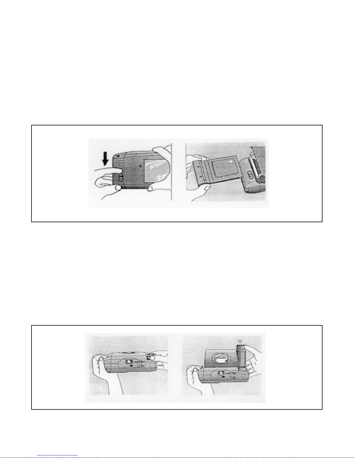
Use only Polaroid Joshua instant film. Film may be loaded (Figure 1-7) with Camera erected or collapsed:
Camera is easier to handle when collapsed. Open film door by sliding the door latch; lift the door up and
slide film pack in. When door is closed and latched, you will hear the film cover (darkslide) transported into
the picture storage compartment and see it in the window; counter will advance to 10.
Fi gur e 1 -7. Loadi n g the Fi lm
Erecting C am e ra
Hold Camera with left hand grasping rubber grip (Figure 1-8). Press button on top of Strobe tower with
right thumb and raise the flash until the Camera clicks into its open position. (The erect linkage on lef t side
of bellows will be firmly l ocked in position and Viewfinder image will not be blocked). Red LED on rear
of strobe will light indicating strobe is charging, followed by green strobe-ready LED. (Strobe shuts off
automatically a f ter 30 seconds to save energy, but will turn on as soon as your finger lightly touches the
sh utter but ton.)
Figure 1-8. Erecting the Camera
1 - 10
Page 17
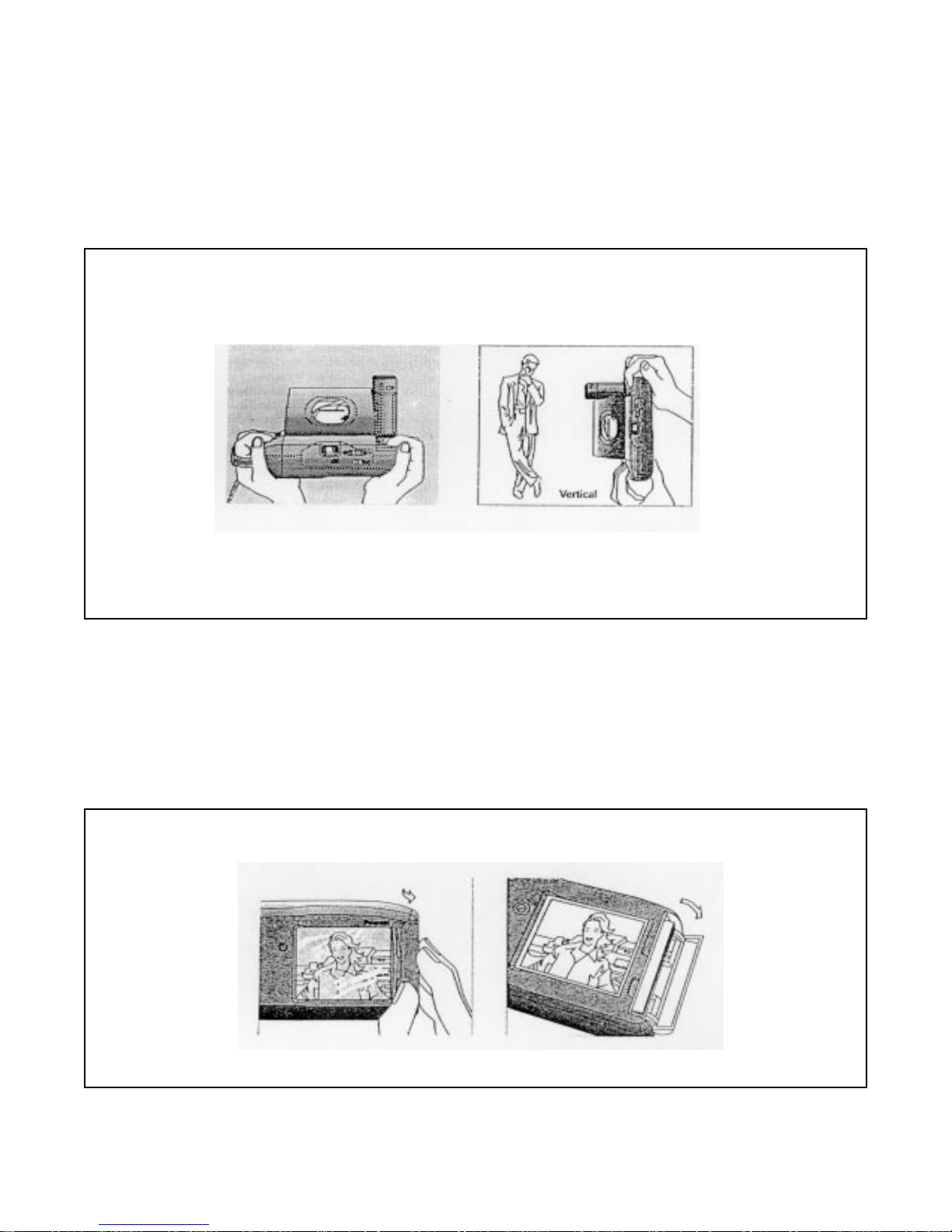
Taking Picture
Hold Camera horizontally or vertically (keep flash on top), frame your picture and press shutter button
(Figure 1-9). (If Viewfinder is black, Ca mera is not fully erected — push flash tower forward until it
clicks.) If green LED is not lighted, touch shutter button l ightly to charge flash. The picture adva n ces
autom atical ly int o the st orage compar tme nt, ov er the p revious p ict ure s.
Figure 1-9. Fram ing and Formatting the Picture
Pictures can be removed immedi ately, by opening the picture removal door, or left in the storage
compartment (Figure 1-10). When the compartment contains 10 pictures plus the dark slide, the camera
beeps and operation is inhibited until the pictures are removed.
Figure 1-10. Viewing and Removing Pictures
1 - 11
Page 18

Brightness Adjustment and Self-Timer
To reshoot a picture that is too dark, move the Brightness Override Switch toward the white-dot arrow
(Figure 1-11). To take a darker picture, move the Switch to the left, toward the black-dot arrow. (Camera
must be erected; Switch will reset to normal when Camera is collapsed.)
To operate Self-Ti mer, set Camera on tripod, frame picture and slide switch toward clock symbol (it will
spring back). Camera will beep and red LED will flash at increasing rate during the next 12 seconds, then
strob e w ill fi re. May be cancelled by pu shi ng swi tch t o r igh t again, or collapsin g C amera, or li ghtly tou ching
the shutter button.
Figure 1-11. Bri g htness (Lighten/Darke n) and Self-Timer Controls
1 - 12
Page 19

Major Functional Subsystems of the Joshua Camera
Note: The following descriptions and illustrations are
intended to famil iar ize y o u with what th e C ame ra
subsystems are. How these subsystems work is
covered in the Theory of Operation section.
Erecting, Viewfinder and Camera Optical System
Figure 1-12 shows in simplified form the linkage which erects the Camera and accurately positions the
optical elements for viewing the scene and exposing the picture. When the release button latch on the top of
the strobe tower is depressed, a latch at the base of the strobe unlatches the top cover. Further rotation of
the strobe tower swings the shut t er assemb ly up to a vertic a l position, where the erecting linkage latches all
pivoted assemblies in place and in proper optical alignment.
Figure 1-12. Erecting Sequence of the Joshua Camera
1 - 13
Page 20
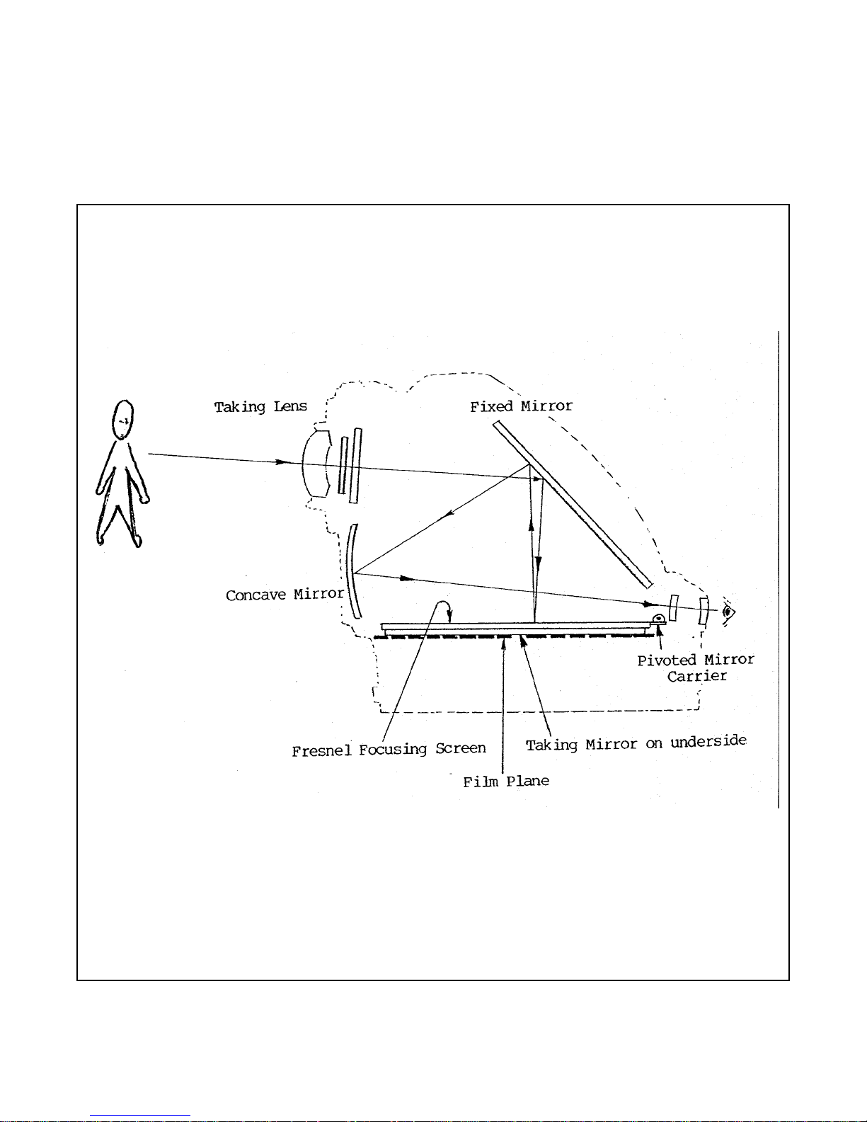
The image path through the single-lens reflex viewfinder, from the scene to the camera user’s eye, is shown
in Figure 1-13. From the taking lens, the im a ge is directed onto a fixed viewing mirror at 45 degrees . . .
then to a textured fresnel focusing screen . . . back to the viewing mirror . . . and then to a concave
mirror, which directs the image of the object through an eyelens to the user’s eye. The visual framing field
equal s the ph otog rap hic field at all di sta nce s.
Figur e 1-13 . Image Pat h through Sin gle -Lens Ref lex Viewf ind er
1 - 14
Page 21

As shown in Figure 1-14, a second mirror — the taking mirror — is mounted on the underside of the fresnel
screen. When the shutter button is fully depressed, the pivoted fresnel screen/taking mirror assembly is
unlatched and driven upward into the optical path to the 45-degree angle position shown. A fraction of a
second earlie r, a blind was moved into place within the viewfinder window to prevent stray light from
reach ing t he fil m.
If the subject is 2.7 m (9 ft.) or more from the Camera (determined automatically from strobe wink
reflectance data), an internal far focus lens is automatically rotated into the optical path, for proper focusing.
Film exposure o c curs as the shutter blades are opened and closed. Then the taking mirror is driven back
down to its original position and the viewfinder blind is opened.
Figure 1-14. Movement of Taking Mirror into Optical Path during Exposure
1 - 15
Page 22

Drive and Switching Systems
Yo u w ill n o te similarit ies between some o f the components of the J o s hua driv e s y s tem s h o wn in Fi g ur e s 115 and 1-16, and comparable parts of Spectra/Image, 640, Impulse and SX-70 drives — for example,
motor-drive n reducti on gea r trai n, sin gle-re voluti on tim ing ge ar with camm ed sur faces, co unter wheel, pick
as sem bly an d w irefo rm s wit che s.
However, many Joshua drive system parts are new and unique. These include:
• Recock Link, one-way wrap-spring Clut ch Gear and Re c ock Latch system for positioning and
returning the Taking Mirror.
• Viewfinder Blind system which prev ents stray light from striking the film during exposure.
• Motor operation in both forward and reverse directions.
• Film frame transport via two pick systems and two sets of rollers. One pick pulls the frame into the
feed rolls which drive it through the “chute”, and a second pick moves the frame into the storage
chamber as it exi ts the s p rea d s ystem rol ler s .
• Separate wireform switchblocks for logic functions and powering the camera:
- A 5-wire “Logic” switch (Figure 1-15) on the gear train side of the drive assembly controls
Electronic Trim, Chamber Full, Self-Timer, End of Pack, Darkslide/ End of Cycle, Shutter
Release and Film Speed functions.
- A separate 3-wire “Erect” (Power) switch (Figure 1-20) l o cated on the opposite side of the
mainframe controls B+, VER and GND lines, and opera tes in conjunction with the Door Latch
Sensor, Erect Sensor, Power Actuator and Film Shade.
Logic Switch (See Switch Block Assembly in Figure 1-16) Power On at Start of Processing (Camera Erect)
Figur e 1 -15 . Log ic Swi tch and Power O n s wit ch
1 - 16
Page 23
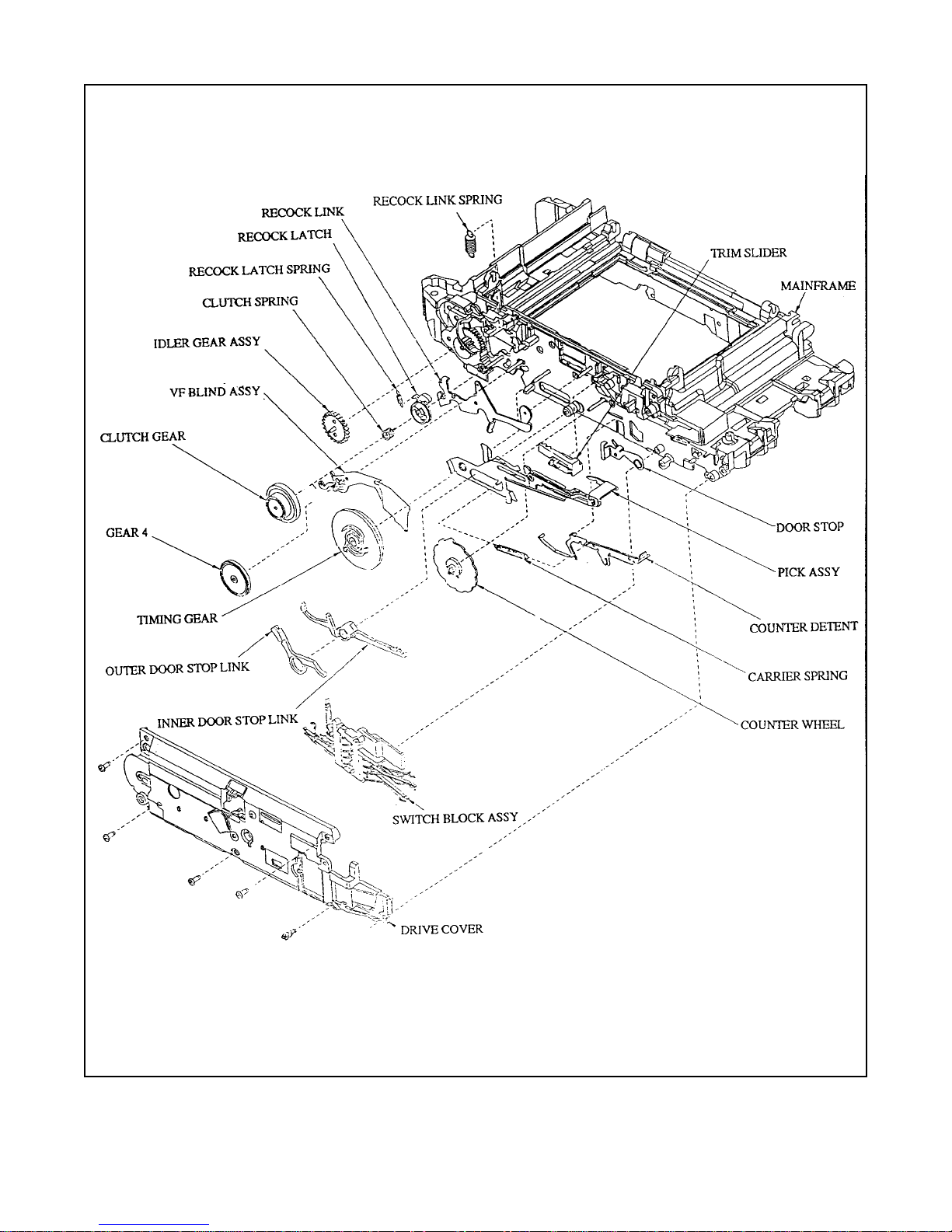
Figure 1-16. Principal Parts of the Joshua Drive System
1 - 17
Page 24
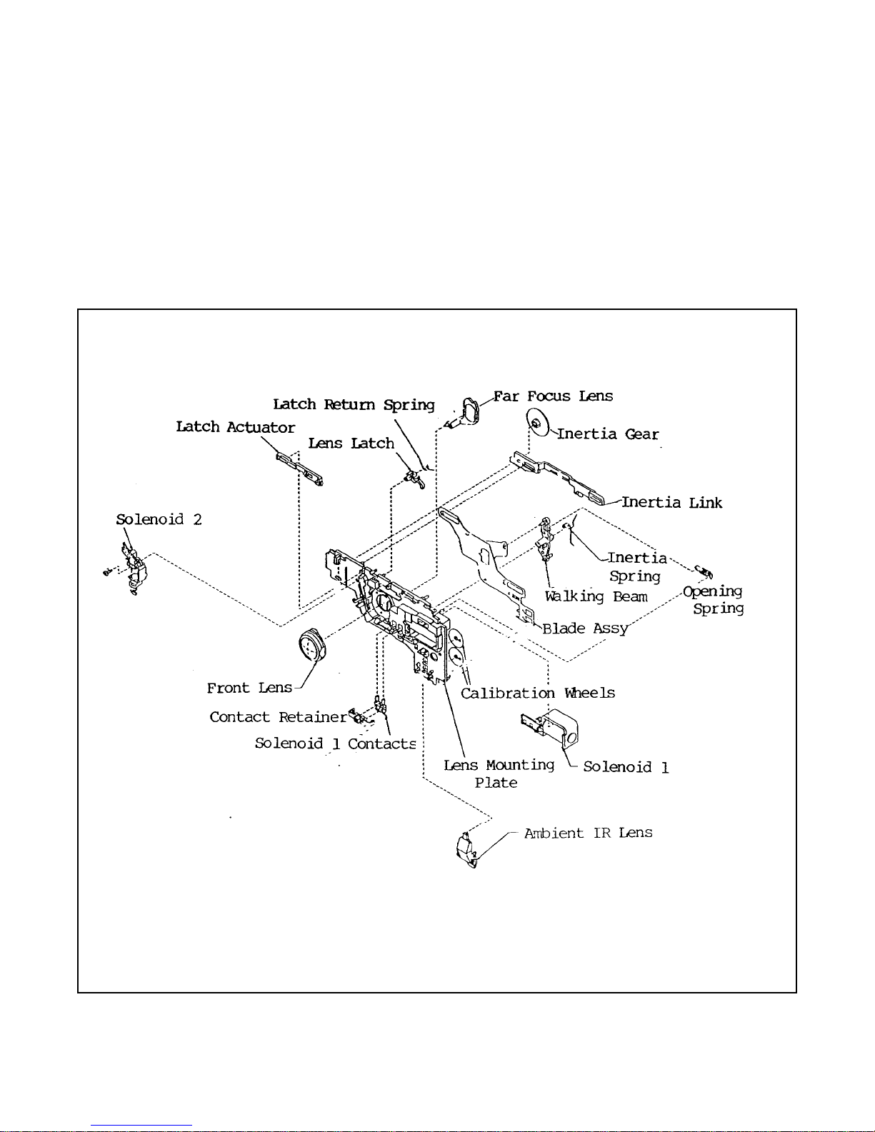
Shutter System (Figures 1-17, 1-18 and 1-19)
Key components of the Joshua shutter system, shown in Figure 1-17, include the Front Lens, Far Focus
Len s an d it s S olenoid 2, Walk ing Beam, I n ert ia S y s tem , the two Blade s a nd their Solenoid 1 a nd Ambient/
IR Lens. The Blade Position En coder system (Figure 1-18) i n cludes the band of vertical slots n e ar the
bottom o f t he Blades , a ph oto diode and ph oto-tr ans ist or (Figure 1 -18 ) o n t he PC board, an d c ircuits in t he
Exposure IC. Because the Joshua is a single-lens reflex (SLR) camera in which the image is viewed through
the t aking len s, the shutt er mus t n ormally b e open for s ubject viewi ng. The Blade Ope nin g Spri ng attach ed to
the W alk ing Beam hol ds the Blade s i n this no rma lly- open po sit ion , unti l they ar e clo sed pri or to exp osu re by
ro tation of th e Walk ing Beam, when Sole noi d 1 is ener gize d.
Figure 1-17. Key Components of the Joshua Shutter System
1 - 18
Page 25

Fi gur e 1-18. J o s hua Bl ade P o s iti on Enc oder Sys t em
Ambient Visible and IR levels are measured by a dual- photocell Photometer on the PC board, through
green and black lenses on the lens mounting plate and corresponding apertures in the shutter blades. Each of
the se expos ure components — ambient an d IR — is in dividual l y int egrated ( ele ctronical ly s um med) by i t s
own integrator.
The Two-Zone Focus System uses, under microprocessor control, the main three-element Taking L ens
only, for ne ar zone (0.6 to 2.7 m or 2 to 9 ft.) exposures — or the main Lens plus the automaticallypositioned Far Focus Lens for exposures between 2.7 m (9 ft.) and infinity (Figure 1-19).
1 - 19
Page 26

The microprocessor determines which zone to use, based on IR reflectance data resulting from the strobe
wink. (Although the electronics uses the wink mode to d etermine whether the subject is near or far from
the camera, the primary purpose of the wink mode is to predict the strobe fire aperture.)
When th e Far Focus Lens is needed, it is pivoted into the opti cal path by Solenoid 2 and latched by the Lens
Latch and Latch Actuator (Figure 1-19).
Figure 1-19. Two-Zone Focus System Components
As exposure begins, the two blades are opened r e latively slowly (about 40 ms from closed to fully open), t o
maximize the amount of ambient light used in the exposure, and the time the blades are at smaller apertures,
to enhance depth of field. The rack and pinion (inertia link and inertia gear, respectively) of t h e inertia
system act as an effective mult iplier of inertial forces, to allow the blades to begin opening slowly. (The
blades are coupled to the Inertia Link and Gear through the Walking Beam and Inertia Spring.)
Blade position is very accurately monitored and controlled by the Blad e Encoder system. The photodiode
encoder pair (on the PC board) and horizontal rows of nine slits in the blades together act as a pulse
generat or, as the slits successiv e ly overlap during blade opening. Because of the accuracy of the Encoder in
supplying blade position/aperture information, no proJoshua for blade speed adjustment is needed in the
Joshua shutter.
The strobe is fired at an aperture selected by the microprocessor from a lookup table, and quenched 2.5 ms
later or when the IR integrator reaches the strobe contribution value selected by the microprocessor.
1 - 20
Page 27

Exposure ends and the blades are closed when the sum of the visible and IR integrator values equals the
selected total. (If this selected total has not been reached when the strobe is quenched, the blades stay open
and the ambient integrator is turned back on (enabled) until additional ambient completes the exposure or a
40 ms Timeout is reached.
To end the exposure and close the bl ades as rapidly as possible, Solenoid 1 is energized and the Inertia is
left behind. A weak Inertia Coupling Spring then resets the inertia to its original position, after the shutter
has c lose d.
N ot e: F o r a si mpl ifi ed pic torial pr es e nta tion of th es e steps ,
see the Exposure section of the Polaroid Joshua
Sequence of Operations chart at the beginning of the
Theory o f Operatio n section . (Se e P age 2- 4)
Film Frame Transport and Spreading (Figures 1-20 and 1-21)
When exposure of a film frame has been completed, the drive motor starts in the forward direction, turning
the Timing Gear. Th is causes: the Darkslide/End of Cycle switch (DKEC) to close; the picture Counter
Wheel to index one count; and the exposed frame to be pulled into a set of two Feed Rolls by a Pick
Assembly.
These rolls have rubber tires (O rings) which contact the fram e along its edges, drive it through the chute
and into the Spread System Rolls (Figure 1-20). Just before the fram e enters the Spread Rolls, it passes
over opposing, slightly projecting molded surfaces on the bottom of the Film Box and part of the Spread
Ro ll A ss embly (Fi gur e 1 -21 ). Thes e mold ed fe atu res help po sit ion the r eag ent mo re evenl y in th e p icture ar ea
bef or e actu al sp read ing oc curs .
At the same time the fra me enters the Feed Rolls, a mechani cal Film Shade (similar in function to the frog’s
tongue in other Polaroid cameras) is automatically positioned over the first 1.9 cm (.75") of the picture
Viewing Window. The Film Shade prevents light-piping fogging of undeveloped film through its
tra ns parent myl ar coa tin g.
The frame now enters the Spread Rolls which break open the reagent pod and spread the reagent. A second
chamber P ick (S ee Figure 2- 27 on Pag e 2 -21 ) i n the Doo r catche s t he end of th e proc ess ed frame fro m the
matin g poi nt ( nip ) of t he Sp rea d Roll s. This is to en sure th at the pr oces se d fram e is p ulled cl ear of the S pread
Ro lls and i s po sitiv ely carr ied int o the pi ctu re S tor age C ham ber , w here i t w ill no t int erf ere w ith the ne xt frame
to be spread.
The film Chute, Chamber and associated transport mechanisms are designed to permit trouble-free insertion
of additional film frames, either from the Chute or through the storage chamber Door, until 10 frames and a
darkslide are in the storage chamber. At that point, a Full-Chamber Switch is closed, inhibiting further
pictu re taki ng.
1 - 21
Page 28

Figure 1-20. Film Frame Transport, Spreading and Storage
Figure 1-21. Features for Even Reagent Distribution in Pod
1 - 22
Page 29

Specification Summary — Joshua Camera
Camera Type Folding, single-lens reflex with integral strobe and picture storage/viewing in
camera.
Film Type Polaroid Joshua instant color print film; 10 exposures per pack with integral
mercu ry- free bat tery.
Frame Si ze 11.1 x 6.4 cm (4-3/8" x 2-1/2").
Image Size 7.3 x 5.5 cm (2-7/8" x 2-1/8").
Focusing System Automatic, two-zone:
• 0.6 m - 2.7 m (2 - 9 ft.).
• 2.7 m - infinity (9 ft. -infinity).
Acces sor y c los e-up lens pe rmits f ixed f ocu s a t 0 .3 m ( 1.0 ft ).
Strobe Range 0.6 m - 3.0 m (2 ft. - 10 ft.).
Strobe Operation SPAR system, hybrid quench, typical recharge time less than 5.3 sec.
Exposure System Strobe-always, fill flash, W ink Aperture Priority (flash fire aperture based on
IR r eflectance and value s e lected from lookup table by microprocessor).
Ov era ll Dimen sio ns • Folded: 57 x 96 x 180 mm (2.25 x 3.79 x 7.1").
• Erected: 114high x 109 deep x 180 wide (mm) (4.48high x 4.29 deep x
7.1" wide ).
Weights • 634 g (22 oz) empty.
• 758 g (27 oz) with film pack.
In dica tors • Empty Film Pack - Red LED flashes eight times,
four beeps sound.
• Strobe Charging or Battery Low - Steady red LED.
• Str obe Rea dy - Stead y green LED .
• Chamber Full or Picture Jam - Red LED flashes eight times,
two-tone beep sounds four
times.
• Self-Timer On - Front red LED flashes
Controls Sh utt er but ton , c ame ra erect, b r igh tne ss adj ust men t, sel f-timer .
1 - 23
Page 30

Components, Covers and Panels
Figure 1-22 on the following foldout page is an exploded view showing principally the removable parts,
panels and covers of the Joshua Camera.
Please note that this illustration is for general informa tion only and NOT i ntended as a disassembly guide or
representation of major sub-assemblies of the camera. (That infor m ation is presented in other sections of
this Ser vice Manual.)
1 - 24
Page 31

Figure 1-22. Joshua Components, Covers,and Panels
1 - 25
Page 32

[This p age inte ntionally blank]
Page 33

2. Theory of Operation
2 - 1
Page 34

2. Theory of Operation
T able of Contents
Seque nce o f Oper ation .......................................................................................................... 2-3
Stages o f Oper ation ............................................................................................................... 2-3
Loading Fil mpack into E rected or Fo lded C amera........................................................... 2-3
Power ing Folde d C amera for Da rk -Sl ide when Fil mpack is Ins erted............................... 2-6
Power ing Camera w hen Film Do o r is Closed , L atched and then Erected......................... 2-8
Maintain ing Po wer fo r Proc ess ing after Camera is F olded............................................... 2-9
Darks lide Transpo rt and Count er Wheel Indexing ........................................................... 2-11
Expos ing the Pi cture........................................................................................................ 2-12
Blocking th e Vi ewf inder ................................................................................................. 2-13
Releasin g the Taking Mirror............................................................................................ 2-14
Proce ssi ng the Ex pos ed Fra me ........................................................................................ 2-16
Reseatin g the Taking Mi rro r and Op eni ng the Vi ewf ind er Blind ..................................... 2-19
Special Cases......................................................................................................................... 2-23
Darkslide when Film Door is Opened and Closed ........................................................... 2-23
Fo lding the Camer a durin g a Proce ssi ng Cyc le................................................................ 2-24
Safety C lut ch on Feed Ro ll .............................................................................................. 2-24
Syste m S chematic.................................................................................................................. 2-24
2 - 2
Page 35

2. Theory of Operation
Sequence of Operation
Figure 2-1 shows an overall, pictorial summary of the entire sequence of operations from power up through
processing, followed by detailed descriptions of what happens during each of the m ajor stages.
Note: A Cir cui t Diag ram of the J os hua Camer a is i ncl ude d at the
end of this section. Refer to the Glossary in the Appendix of this Service
Manual for a definition of the Joshua terms used in this section.
Stages of Operation
Note: To prevent confusion, the terms erected and folded (or collapsed )
will be used to describe the camera position.
Open and closed will be used in reference to camera doors.
Loading Film Pack into Erected or FoldedCamera
Inserting a new fil m pack into the camera, and closing and latching the film door (assuming there are no
pictures in the storage cha mbe r ) re s ult s i n:
• Film pack to be positioned in the film plane.
• Camera to be powered up.
• Darkslide to be transported from the film pack to the picture chamber.
• Picture counter wheel to be indexed from a blank position to the number 10.
• Strobe to be charged, when the camera is erected.
Note: If the pi cture chamber is full, a red warning LED will flash
and a two-t one beep wil l s ound if the camera is ere cted.
When the chamber is emptied, normal darkslide will occur
immediately an d t he cam era will be rea d y fo r u s e.
2 - 3
Page 36

2 - 4
Figur e 2-1. P ictorial Chart Sh owing J oshua Camera S equence of O peration
Page 37

The f ilm pack fra me a nd plate n a sse mbly mou nted on the f ilm loadi ng doo r perm it e asy i nse rti on and re mov al
of a film p ack . As sho wn in Fi gur e 2 -2, these part s ac cur ately p ositi on the to pmos t fr ame in th e co rrect op tical
plane fo r e xpo sur e, when th e door is cl ose d.
Figure 2-2. Film Pack Positioning when Door is Closed
The second result of inserting a film pack and latching the door closed — powering the camera — is
accomplished by the Erect (Power) Switch shown in Figure 2-3, one of two wireform switches in the
Joshua. (The other switch controls logic functions and is located next to the drive mec hanism, timing gear
and pick ca rri er a ssemblies.)
The Erect Switch is located on the opposite side of the mainframe from the drive assembly, near the lower
erect link, door latch and film shade, on which it depends for operation.
Figure 2-3. Erect (Power) Switch (See Figure 2-5)
2 - 5
Page 38

As you would expect, this switch powers the camera circuits after the VER to Gnd contact is opened and
the VER to B+ contact is closed. The VER and B+ wires are variously actuated by the door latch, lower
erect link or the film shade lug, depending on whether the camera is folded or erected.
For clarity, therefore, only the parts which are operative in a given situation will be shown in each of the
fo llowi ng e xplanat ion s.
Powering a Folded Camera when a Filmpack is Inserted
Since film may be loaded when the camera is folded, and because darkslide should occur immediately,
darkslide power is needed in a normally unpowered camera. In the Joshua, this requirement is met by the
action of a Film Shade lug on the Dark Slide Link, a pivoted finger on the Power Actuator.
When th e fil m door is opened, the spring-loaded Dark Slide Link rotates to a downward-pointing position,
becoming a rigid ex tension of the Power Actuator (Figure 2-4).
Figur e 2-4. Film Door Op en
When the film pack is inserted and the door closed, a lug on the Film Shade forces the Dark Slide Link/
Power Actuator assembly upward, raising VER and breaking the VER - GND contact (Figure 2-5).
Figure 2-5. Film Door Closed
2 - 6
Page 39

As the door is l atched, the Door Latch cam rotates the Door Latch Sensor CCW, allowing the B+ wire to
drop and contact VER (Figure 2-6). Power is now made and darkslide occurs. The Film Shade moves to
the left in to its bl ock ing p os iti on, th en return s .
Figure 2-6. Door Closed and Latched
On its return, its lug pushes the Dark Slide Link to the right (Figure 2-7), out of the way, allowing the
Power Actuator assembly to pivot CCW back down again. This allows VER to break contact with B+,
turning off power, and to contact GND again.
N ot e: With an ere cte d camera, th e Dark Sl ide Li nk/ P ow er
Actuator are not needed for darkslide power. Instead,
the Erect Link and Erect Sensor, described later, open
VER to GND, and close VER to B+.)
Figure 2-7. Film Shade Retracted, Power Actuator Pivoted CCW
2 - 7
Page 40

Powering Camera when Film Door is Closed, latched and then Erected
As shown in Figure 2-8, a cam surface on the Door Latch engages the end of the Door Latch Sensor.
Closing and latching the Door pivots the Sensor CCW, allowing the B+ wire to drop, but not far enough to
contact VER when the camera is in the folded position. (The important effect on the power circuit of
latching the Door, as contrasted to simply closing the Door, is discussed below.)
Figure 2-8. Effect of Door Latch on B+ Wire of Power Switch
With the Door closed and latched (the B+ wire down), erecting the camera now causes the Erect Link to
pivot the Erect Sensor clockwise, lifting VER. This movement of VER first breaks the VER to GND
contact, th en make s t he VER to B+ contact (Figure 2-9).
Figure 2-9. Effect of Erect Link on VER Wire of Power Switch
2 - 8
Page 41

If the camera is now folded, the reverse happens: VER opens from B+ and is then short e d to GND. This
discharges a capacitor in the Power Supply, so that when the Camera is later erected, the microprocessor
know s the strobe shou ld be topped off.
As mentioned above, it is the Door Latch, not the Door, that affects the B+ wire of the Power Switch. The
reason is to preven t application of power and motor start when the Door is almost but not fully closed. The
camera could attempt to darkslide and to rotate the drive gears in the Mainframe before they were smoothly
and fully meshed with the gears in the Door. Thus closing the Door has no effec t on the power circuit, but
latch ing the Do o r doe s.
Conversely, using the Door Latch in the power circuit rather than the Door also means that power is cut off
before the Door is opened and the gear mesh is broken. When the Door is unlatched, the Door Latch cam
allows the Door Latch Sensor to pivot upward (CW), driving the B+ wire upward and out of contact with
VER.
Maint ain ing Power fo r Processi ng aft er Cam era is Folde d
Folding t h e camera from an erect position would normally cause the Erect Link and Erect Sensor to shut off
the power, as just described. But folding the camera while a processing cy cle is taking place (after the
mirror is down) must not be allowed to interrupt the power. If it did, the motor would stop in mid-cycle,
ru ining the pictur e.
How does the camera ma intain power long enough to com p lete the processing cycle, after it has been
folded? Figures 2-10 and 2-11 show how the novel Power Actuator Assembly, in conjunction with the
movement of the Film Shade, performs this critic al power-maintaining function.
In Figure 2-10, at the start of the film processing cycle, the camera is erect and power is on because the
Erect Sensor is holding VER in contact with B+. If the camera is now folded, wireform VER would
normally drop down, opening B+ to VER and killing power.
Figure 2-10. Power On at Start of Processing (Camera Erect)
2 - 9
Page 42

But, as sho wn in Figure 2- 11, th e F ilm Sh ade ha s m ove d to the left, into i ts blocki ng pos ition. A lug o n o ne
edge of the Film Shade has slid under the finger on the Power Actuator, pivoting the Actuator upward. The
molded tab or shoulder on the Actuator is now snug up against VER, in contact with B+.
Even if the camera were now folded, pivoting the Er ect Sensor down away from VER, VER is held up in
contact with B+ by the tab on the Power Actuator. Thus power is maintained until the processing cycle is
completed. When the Film Shade retracts and its lug moves to the right (position shown in Figure 2-10), it
allows the spring-loaded Power Actuator to pivot downward again. VER drops away from B+ a nd closes to
GND.
Figure 2-11. Camera Folded; Film Shade Lug Pivots Power Actuator Upward
Keeping VER and B+ Closed
2 - 10
Page 43

Darkslide Transport and Counter Wheel Indexing
The third and fourth results of loading a film pack into the camera are the darkslide cycl e and picture
counter decrementing (counting down) or indexing.
When power is made as VER closes to B+, t h e microprocessor checks the status of the Full Chamber, EOP
(End of Pack) and DKEC (Dark Slide End Of Cycle) Switches. If the picture chamber is not full and the
counter wheel has not reached the tenth exposure, their corresponding switches will be open. The microprocessor will then signal the strobe to recharge (the fifth result of loading th e fi lm pack), and through the
power IC, run the motor because the DKEC switch is closed.
The motor runs, rotating the Timing Gear (see Figure 2-12), which cams the Door Stop Link down to its
DKEC-closed position. (Actually, the DKEC Switch is already closed.)
Figure 2-12. Timing Gear Cam Actuates DKEC Switch through Outer Door Stop Link
Another cam on the Timing Gear advances the Pick Carrier (Figure 2-13), causing the Pick to pull the
darkslide into the Feed Rolls. From there the darkslide hits the Spread Rolls, after which the Chamber Pick
moves the darkslide the final fraction of an inch into the picture storage chamber.
Figure 2-13. Cam Advances and Holds Pick Assembly Forward for Entire Camera Cycle
2 - 11
Page 44

During the forward stroke of the Pick Carrier, the Counter Wheel (Figure 2-14) is indexed by a spring arm
on th e P ick Ca rri er. The Co u nter detent acts as a rat chet.
After one full revolut ion, the Timing Gear cam allows the Outer Door Stop Link to rotate CCW, opening
the DKEC switch which signals the microprocessor to shut off the motor.
Figure 2-14. Counter Wheel Indexed
Exposing the Picture
N ot e: Described b elow are the el ectr ome chanical action s of t he
main drive train which take place du rin g e xp o s ure — ho w the
viewfinder blind and the taking mirror are moved.
For an overall list of the steps in the exposure and processing sequence of operat i ons, see the Sequence of
Op erations cha rt at the begin n in g o f t he The or y of Op eration.
When the shutter release (S1A-S1B) button is depressed, Solenoid 1 is energized and begins closing the
sh utter bl ade s .
The main drive train now has the following tasks: to block the Viewfinder with the Viewfinder Blind
before the Taking Mirror begins to move, to prevent the film from being light- struck; and second, to
release and drive the Taking Mirror into position for exposing the film. Here is how these actions are
accomplished.
2 - 12
Page 45

Blocking the Viewfinder
The motor is momentari ly run in reverse, rotating t h e Recock La tch a short distance counterclockwise
(Figure 2-15). (The L atch, on the same shaft as the Clutch Gear, is turned by the leg of a one-way-slip wrap
spring on the hub of the Clu tch Gear. When the motor reverses the Cl u tch Gear, the spring tightens on its
hub and turns with it, also turning the Recock Latch. When the motor runs forward for the processing
cycle, the spring slips and has no effect.)
Figure 2-15. Recock Latch Rotation by Clutch Gear Spring Leg
Motion of the R e cock L atch is transmitted to the Viewfinder Blind through the Viewfinder Blind Link and
the Viewfinder Overtravel Spring (Figure 2-16).
When th e Latch turns counterclockwise, the Viewfinder Blind Link is driven to the right, rotating one leg of
the Bli nd Overtravel Spring. The Spring, in turn, pivots th e Viewfinder Blind upward, covering the
Viewfinder window comp letely before the Recock Link (and the Taking Mirror) begins to move.
The Viewfinder Blind comes to rest against the upper edge of the Viewfinder Window, however, before the
Recock Latch has finished its rotation. To a ccommodate this, the Blind Overtravel Spring opens up further.
2 - 13
Page 46

Figure 2-16. Recock Latch Pivots Viewfinder Blind Upward Through Viewfinder Blind Link and Blind
Overtravel Spring
Releasin g the Ta kin g Mirror
As previously described, the brief motor reversal rotated the Recock Latch a few degrees counterclockwise.
This ac tion frees the Recock Link to pivot upward from the forc e of the stretched Recock Link Spring (see
Figure 2-17).
As the Re c ock Link swings upward, a shoulder surface on its left end pushes against one edge of the Taking
Mirror Carrier, forcing it into its 45-degree exposure position (Figure 2-18).
Figure 2-17. Recock Link Spring pulls up unlatched Recock Link
2 - 14
Page 47

Figure 2-18. Recock Link Drives Taking Mirror Carrier into Position for Exposure
As described in the Exposure section of the Sequence of Operations, ambient and wink measurements are
now made, strobe fire aperture selected from the lookup table, Solenoid 1 released, blade position carefully
monitored and the strobe is fired — all under microprocessor control.
To end the exposure, Solenoid 1 is again energized to close the shutt e r blades. If the Far Lens was used for
the exposure, it is now unlatched and spring-returned to its normal position, out of the optical path. The
exposed frame is now ready for processing.
2 - 15
Page 48

Processing the Exposed Frame
The motor now runs forward, rot ating the Timing Gear which cams the Outer Door Stop Link to close
DK EC (Figur e 2-19).
Another cam, on the underside of the Timing Gear, drives the Pick Carrier forward (to the left) to its full
stroke and holds i t there (Figure 2-20). A spring arm on the Pick Carrier indexes the Counter Wheel
(Figure 2-21).
Figure 2-19. Timing Gear Cam Lifts Outer Door Stop Link to Close DKEC
Figure 2-20. Timing Gear Pick Advance cam (On Underside) Advances and
Holds Pick Assembly Forward
2 - 16
Page 49

Fi gur e 2- 21 . Spr ing Ar m o n P ick Car rie r I nde xes Co unt er Whe el
The Pick Carrier also drives the Override Slider in the Door. The Slider actuates the Film Shade through a
reversing linkage, moving the Film Shade into position to cover approximately the first 1.9 cm (.75") of
unexposed film (Figure 2-22).
Figure 2-22. Override Slider in Storage Pick Assembly Pivots Film Shade Actuator Link
2 - 17
Page 50

The e xpo s ed fr ame is no w p ul led in to the Fe ed Rolls by the no tch ed Pic k S tra p — a pi vot ed, sprin g-l oad ed
arm attached to the end of the Pick Carrier (see Figure 2-23). The Feed Rolls drive the fra me around the
chute.
Figure 2-23. Pick Strap on Pick Carrier Pulls Frame into Feed Rolls
The Pick Strap in the Joshua System, which pushes the film fra me into engagement with the Feed Rolls, is
specifically designed to provide a more positive grip on the film fr a me.
Spring force in a downward direction keeps the Strap in constant contact with the film frame surface, and a
sharp, inclined notch assures positive engagement with the edge of the frame.
2 - 18
Page 51

Reseating the Taking Mirror and Opening the Viewfinder Blind
To return the Taking Mirror to its down position, the Recock Link is pivoted downward by yet another cam
on the underside of the Timing Gear (Figure 2-24).
Fi gur e 2 -24 . Taking Mi rro r C arri er Dr i ven Do wn by Recock Link
As the Recock Link swings down, it pulls the Taking Mirror Carrier down, through the Midlink and Mirror
Hold-Down Spring. This spring coupling is a safety proJoshua which allows the Recock Link to continue to
move, even if something impedes th e motion of the Taking Mirror Carrier (e.g., finger in the bellows).
The Viewfinder Blind is opened, uncovering the Viewfinder Window, after the Taking Mirror Carrier is
seated. This action happens during Recock Link overtravel, when the Recock Latch rotates to the latched
position (Figure 2-25).
Figure 2-25. Viewfinder Blind Opened by Recock Latch Rotation
2 - 19
Page 52

The Latch is rotated by a combination of the Recock Latch Spring and the drag of the spring clutch in the
overrunning direction. As the Recock Latch rotates clockwise, it pulls the Blind down through the
Viewf inder Bli nd Link, unc over ing th e V iewfin der Windo w.
The Timing Gear has now rotated to a position where its DKEC cam releases the Outer Door Stop Link,
opening the DKEC switch. This signals the micro to open the shutter blades. The Outer Door Stop Link is
cammed up again, closing the DKEC switch.
The sequence of DKEC switch actuations by the Timing Gear cam can be seen in Figure 2-26. At the
beginning of a cycle, the Timing Gear cams the Door Stop Link to cl ose the switch.
Half-way through t h e cycle, the Door Stop Link momentarily opens and then recloses the switch (as
described above), signalling that the mirror is down. This mirror down signal lets the electronics know that
the Viewfinder Blind can be opened, so that with the shutter blades reopened, the Viewfinder does not
remain dark.
At the end of the cycle, the DKEC switch opens again, shutting off the motor.
Figure 2-26. DKEC Switch Actuations by Timing Gear During Normal Cycle
2 - 20
Page 53

The fin al stages of processing involve the frame being fed into the Spread Rolls and spread, and the Timing
Gear rotating to a position where the Pick Carrier Advance/Hold Forward cam on its underside allows the
Pick Car rie r t o retract under its ow n s pri ng tensio n.
The Override Slider (part of the Storage Chamber Pick Assembly), under its own spring load, follows the
Pick Carrier. This causes the Chamber Pick first to advance and then re tract (inset, Figure 2-27), pulling
the fra me a short distance clear of the Spread Rolls and into the storage Chamber (Figure 2-27). This
prevents possible interference as the next frame moves through the Spread Rolls.
The Film Shade now retracts, and the Outer Door Stop Link opens the DKEC Switch a second time,
shutting off the motor.
Figure 2-27. Chamber Pick Pulls Processed Fram e Clear of Spread Rolls and intoCchamber
2 - 21
Page 54

The process is repeated until all 10 film fram es have been processed and transported to the Storage
Chamber. The 10 film frames and the dark slide will now cause the Full ChamberLink to close the Full
Chamber contacts of the Logic Switch (Figure 2-28), preventing further operation until th e chamber is
emptied. T he F ul l Chamber S witch i s a lso used to det ect film jams . Duri n g e ach no rma l c ycle, the F u ll
Chamber Switch is closed and remains closed unt il the end of the cycle, when it opens.
Should a jam occur, the Chamber Pick wil l be unable to retract, in turn preventing the Full Chamber switch
from reopening. The camera logic then inte rprets this as a jam, triggering audible and LED alarms.
Figure 2-28. Full Chamber Switch Contacts in Logic Switch
2 - 22
Page 55

The End of Pack Switch (Figure 2-29) is operated by a cam on the Counter Wheel, when the Wheel reaches
the 0 posi tio n.
Figure 2-29. End of Pack (EOP) Switch and Counter Wheel Cam
Special Cases
Darkslide when Film Loading Door is Opened and Closed
When th e Door is opened to remove/replace film or c lean the Spread Rolls, the Pack Frame drives down the
Door Stop (See Figure 2-30).
Figure 2-30. Effect of Door Stop on Inner and Outer Door Stop Links and DKEC Switch
2 - 23
Page 56

This rotates the Inner Door Stop Link far enough to be caught by the Pick Carrier, which acts as a detent.
Rotation of the Inner Door Stop Link also rotates the Outer Door Stop Link, closing the DKEC switch.
Closing t h e Film Door rotates the Door Stop back up, but the Door Stop Links remain in their detented
position.
When th e micro senses the DKEC closed at the beginning of a cycle (power up), it interprets this as a do a
da r k slide command and causes the camera to automatically go through a normal processing
cycle (no
motor reverse or mirror release). This is an important action for mid-cycle clearing. The Inner Door Stop
Link is released when the Pick Carrier is driven forward, but the DKEC Switch remains closed. (The
Timing Gear has rotated far enough to prevent the Outer Door Stop Link from dropping.)
The camera then acts as it would in a normal cycle.
Foldin g the C amera during a Processing Cycle
The cycle wi ll end on the r eturn of the Pick (so-called ma int aining p owe r).
When the Camera is erected the next time, the DKEC Switch will still be closed a nd the motor wi ll run
forward very briefly. It will stop very soon, when the Outer Door Stop Link drops off its Timing Gear cam
and opens the DKEC Switc h, bringing the system to i ts normal stopping point. This brief motor run is
referred to as a hiccup.
System Schematic
Figure 2-31 shows the Circuit Diagram for the Joshua Camera.
2 - 24
Page 57

2 - 25
Figure 2-31. Circuit Diagram
Page 58

[This p age inte ntionally blank]
Page 59

3. T esting and Adjustments
3 - 1
Page 60

3. Testing and Adjustments
T able of Contents
Ge n er a l .................................................................................................................................. 3-3
Required Equipment ........................................................................................................ 3-3
Desc ription o f Equipme nt................................................................................................. 3-3
Tes ting................................................................................................................................... 3-5
Ambient Exposure Test.................................................................................................... 3-5
Strob e Exposure Test ....................................................................................................... 3-8
Adj us tment s ........................................................................................................................... 3-1 0
Amb ient Expos ure Calibration .......................................................................................... 3-1 0
Stro be Exposure Calibration ............................................................................................. 3-12
3 - 2
Page 61

3. Testing and Adjustments
General
The following paragraphs list and describes the required equipment necessary to test and make adjustments
to the Joshua camera.
Required Equipment
• Joshua Test Cover (Part Number 13552)
• Joshua Horn Assembly ( Part Number 13532)
• Align men t G aug e (Part Numbe r 1355 1)
• Base Riser (Part Number 13559)
• Star Tester (Part Number 12650-2)
Description of Equipment
Joshua Test Cover
The Joshua Test Cover (Figure 3-1) cont ains a test switch that is used to switch from the Strobe (STB) to
the Ambient (AMB) t est mode. It also inhibits the strobe and the IR input to the Joshua camera exposur e
system w hile taking Ambient measu rement s.
Important: The Joshua Test Cover must be used for the Ambient and Strobe exposure
test.
Figure 3-1. Joshua Test Cover
Joshu a Horn Assembly
The Joshua Horn Assembly (Figure 3-2), as with previous horn assemblies, allows exposure tests to be
performed with the Star Tester. However, this horn assembly has many differences in terms of its
3 - 3
Page 62

mechanical and electron ic compo nen ts. B ecause electron ic noise is dev elope d d uring each c ycle o f t he
Jo shua camera, ga ting circ uit ry has be en add ed to the horn assembly to eli minate an y d eve lop ed noise
during an Amb ient or Strobe Exposure Test.
This hor n a sse mbly h as fiv e ( 5) extern al compon ent s: Two sw itches (SW 1 an d S W 2 ), two LED 's (G ree n and
Red) and on e photo tran sis tor. Switch 1 (SW 1) is used to toggle fr om its St rob e to A mbient mode of
op era tion. T he two LE D ' s indicate th e state of the St robe mode . The green LED l ights to i nd ica te whe n t he
Str ob e m ode is in its ready state. Th e r ed LED li ght s t o i ndi ca te wh e n t he Str obe mode i s in its not ready
state. Pu s hbu tton switch 2 (SW 2) can b e u sed to pl ace th e Str obe mo de in its ready state.
Du ring the Str obe mode of operat ion, the pho to tra nsis tor det ects both the w ink an d stro be pul se. The Gr een
and R ed LED' s turn on/o ff during t his pe riod ( thi s i s p art of the g ating function of the h orn as sem bly ).
Fo r A mbi ent me asu rement s, Sw itch 1 (S W 1 ) must be se t to its Amb ien t ( AMB ) pos ition . The int ern al
electronics of th e horn as sembly controls the gating function for the Ambient m ode of op eration.
HORN
SWITCH 1
RED LED
Align ment Gau ge
The alignment Gauge (Figure 3-4) is used in place of the 640 Nest Assembly on the Star Tester for the
Joshua camera. It references the Joshua camera photoc ell and taking lens of the c amera to the light source
of the Star tester.
Base Riser
The Base Riser (Figure 3-4) is used to vertically align the Joshua camera to the Star Tester. If th e Star
Tester has leg risers, the Bas e Riser must be used. If it does not have le g risers, the Ba s e Riser sho u ld not be
used.
GREEN LED
SWITCH 2
Figure 3-2. Joshua Horn Assembly
3 - 4
Page 63

Testing
Am bie nt Expo s ure Te s t
Purpo se
The A mbi ent Expos ure Tes t is us ed to mea sur e the ene rgy of th e f ilm pl ane d uri ng an ambien t ( vis ibl e)
ligh t ex pos ure . The St ar Te ster light integ rat ing sp here p ro vide s a co nst ant scene br igh tne ss lev el o f
100 candles/ft
2
.
Setup (F igure 3-3)
1. Open the camera doo r.
2. Us ing a sol der aid tool, m anually trip the camera doo r swit ch into its d own p osition.
3. Us ing a sol der aid t ool, r emove the fr ont cover from the camer a.
4. Install the Joshua Test Cover in place of the removed front cover.
5. Set the Joshua Test Cover Strobe/Ambient(STB/AMB) switch to its Ambient (AMB) position.
6. Place the camera with the Joshua Test Cover onto the Joshua Horn Assembly.
7. Re mov e the 640 Nest As s embly f rom th e Star Teste r.
CAMERA
CAMERA DOOR
SWITCH
JOSHUA TEST
COVER
AMBIENT/STROBE
TRIM WHEELS
JOSHUA HORN
ASSEMBLY
Figure 3-3. Ambient Exposur e Test Setup
3 - 5
Page 64

8. In s ta ll the Alignment G au g e i n place of the removed 640 Ne s t Asse mbl y .
9. Position the Joshua Horn Assembly up against the Star Tester (Figure 3-4). Th e tab guide on the
Al ign ment G aug e p rop erly cent ers th e came ra in fr ont of the li ght s ou rce win dow of the S tar Te ste r.
No t e : The VIS/IR pho tocell an d the taking lens shoul d b e cent ered o n t he lig ht s ou rce wi ndo w .
10. Set switch 1 (SW 1) of the Joshua Horn Assembly to its Ambient (AMB) position.
11 . Sl ide the came ra tri m swit ch to its cente r (normal) p ositio n.
12. Set the Sta r Tester selector sw itch to i ts AM BIEN T positio n.
AMBIENT
ALIGNMENT GAUGE
TAB GUIDE
Figure 3-4. Positioning Camera on Horn Assembly against Star Tester
STOPS ERRORS
CAMERA
BASE RISER
3 - 6
Page 65

Test Proc edu re
1. Press the camera shutte r button.
2. Record readings shown on th e STOP ERROR display of the Star Tester.
3. Repeat steps 1 a nd 2 two more times, recording all reading shown on the STOP ERROR display of
the Star Tester. (Because of the SLR system there is only one reading for e v ery two cyc les of the
camera.)
Note: Ambient Specification Limits -.10 +
0.25 STOP
4. If the STOP ERROR d isplay readings are within specification, proce e d to the Strobe Exposure
(G raywal l) Test.
5. If the STOP ERROR display readings are not within specific ations, perform the Ambient Exposure
Calib ration pr ocedure.
3 - 7
Page 66

Strobe Exposure Test
Purpose
The S trobe Expos ure Test is use d to m eas ure th e r esu ltant ene rgy of th e film pl ane du rin g a 4. 5 f t.
(137 cm) Strob e (Gra yw all) l ight e xposur e.
Setu p (Fig ure 3- 3)
1. Open the ca mer a door .
2. Us ing a sol der aid tool, m anually trip the camera doo r swit ch into its d own p osition.
3. Us ing a sol der aid t ool, r emove the fr ont cover from the camer a.
4. Install the Joshua Test Cover in place of the removed front cover.
5. Set the Joshua Test Cover Strobe/Ambient (STB/AMB) switch to its Strobe (STB) position.
6. Place the camera with the Joshua Test Cover onto the Joshua Horn Assembly.
7. Place the Joshua Horn Assembly on top of the Star Tester (Figure 3-5) at a marked position
137 CM (4.5 Feet) from the Graywall Target.
4.5' (137CM)
STAR TESTER
4'
(1.2 M)
4' (1.2 M
GRAYWALL
TARGET
Figure 3-5. Locating Joshua Horn Assembly and Camera in Rel ation to Graywall Target
3 - 8
Page 67

8. Center the Joshua Horn Assembly on the Star Tester with respect to the Graywall. T he camera
lens must be 4.5 feet (137 cm) from the Graywall.
N ot e: The f ron t of t he cam era mu st be par all el to the G ray wal l and the ar ea vi sibl e in i ts
viewfinder must be free of all objects.
9. Set switch 1 (SW 1) of the Joshua Horn Assembly to its Strobe (STB) position.
10 . Sl ide the came ra tri m swit ch to its cente r (normal) p ositio n.
11. Set the Star T ester sel ector swit ch to its FL ASH EXP posi tion.
Test Proc edure
1. Pr es s th e c amer a sh utter bu tto n.
2. Record readings shown on th e STOP ERROR display of the Star Tester.
3. Repeat steps 1 a nd 2 two more times, recording all reading shown on the STOP ERROR display of
the Star Tester. (Because of the SLR system their is only one reading for every two cycles of the
camera.)
Note: Strobe Specification Limits -.10 +
0.25 STOP
4. If the STOP ERROR display readings are not within specifications, perform the Strobe Exposure
Calib ration pr ocedure.
3 - 9
Page 68

Adjustments
Ambient Exposure Calibration
Setup (Figure 3-3)
1. Open the c amera doo r.
2. Us ing a sol der aid tool, m anually trip the camera doo r swit ch into its d own p osition.
3. Us ing a sol der aid t ool, r emove the fr ont cover from the camer a.
4. Install the Joshua Test Cover in place of the removed front cover.
5. Set the Joshua Test Cover Strobe/Ambient (STB/AMB) switch to its Ambient (AMB) position.
6. Place the camera with the Joshua Test Cover onto the Joshua Horn Assembly.
7. Remove the 640 Nest Assembly from the Star Tester.
8. In s ta ll the A l ignment G a ug e i n p la ce of the removed Ne s t Asse mbl y.
9. Position the Joshua Horn Assembly up against the Star Tester (Figure 3-4). Th e tab guide on the
Al ign ment G aug e p rop erly cent ers th e came ra in fr ont of the li ght s ou rce win dow of the S tar Te ste r.
Note: The V I S/ IR p ho toc ell an d t he tak ing lens should b e centere d o n the light sou rce wi ndow.
10. Set switch 1 (SW 1) of the Joshua Horn Assembly to its Ambient (AMB) position.
11. Slide the camera trim switch to its center (norma l) position.
12. Set the Star Tester selector switch to its Ambient position.
Adjustment Procedure
1. Pr es s th e c amer a sh utter bu tto n.
2. Record readings shown on the STOP ERROR display of the Star Tester.
3. Repeat steps 1 and 2 two more times, recording all reading shown on the STOP ERROR display of
the Star Te st e r. (Beca u s e of the SL R s y stem ther e i s o nl y one read ing for every t wo cycles o f t he
camera . )
Note: Ambient Specification Limits -.10 +
0.25 STOP
3 - 10
Page 69

4. If the STOP ERROR display readings are not within specifications, adjust the Ambient Calibration
wh eel (F igure 3- 6) w ith a den tal pi ck. R otate wh eel clock wis e (CW) to de crease expos ure or count er
clock wise (CCW) to i ncrease expo xure.
5. Re test the cam era. If necess ary, repe at thi s calibr ation proced ure un til Ambie nt expos ure is
correct.
AMBIENT TRIM
WHEEL
JOSHUA TEST
COVER
CAMERA
STROBE TRIM
WHEEL
JOSHUA HORN
AS SEMB LY
Figur e 3-6. Ambient/Strob e Exposure Adj ustments
3 - 11
Page 70

Strobe Exposure Calibration
Setup (Fig ure 3- 3)
1. Open the camera door .
2. Us ing a sol der aid tool, m anually trip the camera doo r swit ch into its d own p osition.
3. Us ing a sol der aid t ool, r emove the fr ont cover from the camer a.
4. Install the Joshua Test Cover in place of the removed front cover.
5. Set the Joshua Test Cover Strobe/Ambient (STB/AMB) switch to its Strobe (STB) position.
6. Place the camera with the Joshua Test Cover onto the Joshua Horn Assembly.
7. Place the Joshua Horn Assembly on top of the Star Tester (Figure 3-5).
8. Center the Joshua Horn Assembly on the Star Tester with respect to the Graywall. T he camera
lens must be 4.5 feet (137 cm) from the Graywall.
N ot e: The f ront o f t he cam era must b e par all el to the G ray wa l l a nd the ar ea v isible i n its
viewfinder must be free of all objects.
9. Set switch 1 (SW 1) of the Joshua Horn Assembly to its Strobe (STB) position.
10 . Sl ide the came ra tri m swit ch to its cente r (normal) p ositio n.
11. Set t he Star T est er selecto r switch to it s Flas h p os i tio n.
Adjustm e ntProce d ure
1. Pr es s th e c amer a sh utter bu tto n.
2. Record readings shown on th e STOP ERROR display of the Star Tester.
3. Repeat steps 1 a nd 2 two more times, recording all reading shown on the STOP ERROR display of
the Star Te st e r. (Beca u s e of the SL R s y stem ther e i s o nl y one read ing for every t wo cycles o f t he
camera.)
Note: Strobe Specification Limits -.10 +
0.25 STOP
3 - 12
Page 71

4. If the STOP ERROR display readings are not within specifications,ad just the Strobe Exposure
Calibration Wheel (Figure 3-6) with a dental pick. Rotate wheel clockwise (CW) to decrease
exposure or counter clockwise (CCW) to increase exposure.
5. Re test the cam era. If nec ess ary, repe at this calibratio n proc edure unt il the Strobe exposure is
correct.
3 - 13
Page 72

[This p age inte ntionally blank]
Page 73

4. Disassembly and Reassembly
4 - 1
Page 74

4. Disassembly and Reassembly
T able of Contents
Introduction ........................................................................................................................... 4-4
Special Tools and Eq uipment Needed ................................................................................... 4-4
Disas sem bly and Assem bly Pr ocedur es ................................................................................. 4-5
Rear Panel ....................................................................................................................... 4-5
Remov al .................................................................................................................... 4-5
Disa ssemb ly .............................................................................................................. 4-5
Reas sembl y ............................................................................................................... 4-7
Front Panel ...................................................................................................................... 4-8
Removal .................................................................................................................... 4-8
Reassembly ............................................................................................................... 4-8
Left Hand G rip and Bottom Chu te Cover ........................................................................ 4-9
Remov al.................................................................................................................... 4-9
Reas s embl y ............................................................................................................... 4-9
Bottom C hu te Cov er........................................................................................................ 4-10
Disa sse mb ly .............................................................................................................. 4-10
Reas s embl y ............................................................................................................... 4-10
Right Hand Grip .............................................................................................................. 4-11
Disassembly .............................................................................................................. 4-11
Reassembly ............................................................................................................... 4-11
Bottom D oor A ss emb ly ................................................................................................... 4-12
Remov al.................................................................................................................... 4-12
Disa sse mb ly .............................................................................................................. 4-12
Reas s embl y ............................................................................................................... 4-15
Top Cov er ....................................................................................................................... 4-16
Remov al.................................................................................................................... 4-16
Reas s embl y ............................................................................................................... 4-17
4 - 2
Page 75

Shutt er Assemb ly ............................................................................................................ 4-18
Remov al .................................................................................................................... 4-18
Disa ssemb ly .............................................................................................................. 4-22
Reas sembl y ............................................................................................................... 4-27
Erect Syste m (V MC /Bello ws and T aking Mir ror Ca rrier A ss emblies )............................. 4-28
Disa sse mb ly .............................................................................................................. 4-28
Reas s embl y ............................................................................................................... 4-30
Main Fra me (Non -Ge ar Sid e) .......................................................................................... 4-31
Disa sse mb ly .............................................................................................................. 4-31
Reas s embl y ............................................................................................................... 4-32
Main Fra me (Gear Side - Outer)...................................................................................... 4-33
Disa sse mb ly .............................................................................................................. 4-33
Reas s embl y ............................................................................................................... 4-34
Main Fra me (Gear Side - Inner) ...................................................................................... 4-35
Disa sse mb ly .............................................................................................................. 4-35
Reas s embl y ............................................................................................................... 4-35
4 - 3
Page 76

Introduction
The following procedures and illustrations cover complete disassembly of the Vision Camera and all Vision
sub-assemblies. However, for many repairs, it is not necessary to completely disassemble the entire Vision
Camera. Only certain pan els, subassemblies or adjacent parts need to be removed to gain access to the par t
to be repaired or replaced. Reassembly proce dures are provided for the more complex sub-assemblies (for
example, the shutter and the gear trains). To reassemble Vision Camera assemblies, follow the disassembly
procedures in r e verse order.
Special Tools and Equipment Needed
Too ls an d e quipment neede d f o r the di s assembly an d r e as se m bly of th e Visi on Camera s u ba s se mblies are:
• Batt ery Conta cts GO/NO-GO Gauge (# 13558)
• Needl enose Pliers
• Tweezers
• Dental Pick
• Sq uar e D rive Hand le ( # CP S 41 6 )
• Sq uare D rive Bi t (# 1 355 3)
• Jewe ler's S crewd rivers
• So lder A id Tool (# 9411 68)
• Narro w Blade (Not ched) Fl at Screwdriver (#1 3560)
• Mid-L ink Insta llation Tool ( # 1355 7)
• Du mp Probe (# 1 311 9)
• Shutt er Sup port Fixtur e (# 1 3556)
4 - 4
Page 77

Disassembly and Reassembly Procedures
Rear P anel
1. Re mov al (Figure 4-1)
a. Using a square drive, remove the three (3) screws tha t secures the Rear Panel to the Main
Body of the camera.
b. Using a solder aid tool, gently pry up the Rear Panel to re lease it from the Main Body of the
camera.
c. Lift off the Rea r Pane l.
CAMERA
2. Disassembly (Figure 4-2)
a. Using tweezers, remove the Self Timer Return Spring (Also used as Power Actuator Spring)
from the Self Timer Button.
b. Us ing a solder aid tool , gen tly pr y up t he Self T imer B utton to releas e it fro m the Rea r P anel. Lift
off t he Sel f Timer Button.
REAR PANEL
Figure 4-1. Removal of Rear Panel
4 - 5
Page 78

c. Using a solder aid tool, gently pry up the light/dark Trim Button to release it from the Rear
Panel. Lift off the Trim Button.
d. Using a solder aid tool, gently pry the plastic loc k ing tab of the Control Panel Decorative Plate
to rel ease it from the Rear Panel. Lift off the Control Panel Decora tive Plate b e ing careful not
to loose the c o un ter Window (Lens) .
Note: The Counter Window (Lens) will fall out as the Control Panel Decorative Plate is
removed.
SELF TIMER
RETURN SPRING
SELF TIMER
BUTTON
PLASTIC LOCKING
TAB
COUNTER
WINDOW (LENS)
CONTROL PANEL
DECORATIVE PLATE
LIGHT/DARK
TRIM BUTTON
REAR PANEL
FLAT SURFACE OF
COUNTER WINDOW
(LENS) FACES
BOTTOM OF
DECORATIVE PLATE
Figure 4-2. Disassembly of Rear Panel
4 - 6
Page 79

3. Reassembly
To reassemble and reinstall the Rear Panel, follow the disassembly steps in reverse order.
N o t e : When instal lin g t he Re ar Pan el onto t he Mai n Body of th e camera ma ke sure:
• Flat part of the Counter Window (Lens) is facing the bottom of the Control Panel
Decorative Plate.
• Self-Timer and Light/Dark Trim tabs (Figure 4-3) are positioned so that each one
properly inserts into the Main Body of the camera.
BRIGHTNESS OVERRIDE
(LIGHT/DARK) SWITCH
CAMERA
SELF-TIMER SWITCH
Figure 4-3. Location of Light/Dark Trim Tabs
LIGHT/DARK TAB
SELF-TIMER TAB
REAR PANEL
4 - 7
Page 80

Front Panel
1. Re mov al (Figure 4-4)
a. Using a square drive, remove the three (3) screws that secures the Front Panel to the Main
Body of the camera.
b. Using a solder aid tool, gently pry up the Front Panel to release it from the Main Body of the
camera.
c. Lift off the Front Panel being careful not to break its plastic locking t ab.
CAMERA
FRONT PANEL
Fi gur e 4- 4. Removal of Fro nt Pan el
2. Reas semb ly
To reinstall the Front Panel, fol l ow the removal steps in reverse order.
PLAST IC
LOCKING
TAB
Note: When re-installing the Front Pane l make sure the plastic locating tab is properly positioned
before inserting the Front Panel into the Main Body of the camera.
4 - 8
Page 81

Left Hand Grip and Bottom Chute Cover
1. Re mov al (Figure 4-5)
a. Open the c ame ra doo r.
b. Using a square drive, remove the two (2) long neck strap screws that clamps the Left Hand Grip
andBottom Chute Cover to the Main Frame of the camera.
c. Gently lift off the Left Hand Grip and the Bottom Chute Cover. If necessary, use a solder aid
tool to separat e the two parts from the Main Frame of the camera.
LEFT HAND
GRIP
STRAP
BOTTOM CHUTE
COVER
LONG NECK
SCR EWS
CAMERA
CAMERA DOOR
COVER LATCH
SHORT SIDE OF
STRAP FACES IN
Figur e 4-5. Removal of Left Han d Grip an d Bottom Chu te Cover
2. Reassembly
To reinstall the Left Hand Grip and Bottom Chute Cover, follow the removal steps in reverse order.
Note: When re-installing the Left Hand Grip and the Botto m Chute Cover make sure:
• Cover latch is released (to release push up metal tab).
• Neck Strap is properly positioned around the screw posts (Short side of the strap faces in
on bo th si des ).
• Neck Strap M UST b e re-inst alled or light leaks may o ccur.
• Both lon g n eck sc rew s M US T be ti ght or li ght le aks may o ccu r.
4 - 9
Page 82

Bottom Chute Cover
1. Disassembly (Figure 4-6)
a. R emove Neck Strap from the screw posts.
b. Using tweezers, remove the Door Latch Return Spring from the Door Latch and the Bottom
Chute C ove r.
c. Using a narrow blade flat screwdriver, gently pry up the Door Latch locking tab to release it
from theBottom Chute Cover. Lift off the Door Latch.
DOOR LATCH
LOCKING TAB
BOTTOM CHUTE
COVER
DOOR LATCH
DOOR LATCH
RETURN SPRING
Figure 4-6. Disassembly of Bottom Chute Cover
2. Reassembly
To reassemble the Bottom Chute Cover, follow the disassembly steps in reverse order.
4 - 10
Page 83

Right Hand G rip
1. Disassembly (Figure 4-7)
a. Open the Picture Removal Door to expose the Right Hand Grip holding screw.
b. Using a square drive, remove the screw that secures the Right Hand Grip to the Main Body of
the camera. Lift out the Right Hand Grip.
c. Pull out th e S 1 B u tto n .
ACTUATOR TAB
S1 BUTTON
POST
RIGHT HAND
GRIP
PICTURE
REMOVAL
DO OR
Figure 4-7. Disassembly of Right Hand Grip
2. Reassembly
To reassemble the Right Hand Grip and S1 Button, follow the disassem b ly steps in reverse order.
No te : Wh en re-ins talling the Right Hand Grip and S1 But ton make sur e the S1 Button: (Se e insert
in Fi gure 4- 7)
• Actuator tab is properly inserted into its locating slot on the Main Body of the camera.
• S1 Button is properly placed on its support post on the Main Body of the camera.
S1 BUTTON
ACTUATOR TAB
4 - 11
Page 84

Bottom Door Assembly
1. Removal
a. Using a narrow bla d e flat screwdriver or tweezers, lift out the pins (Figure 4-8) that hing e the
Bottom Door Assembly to the Main Body of the Camera.
b. Gentl y Squeeze th e P ack Frame together to disconnect it f r om the D oor St o ps on the Main Bo dy
of the c amera . L ift ou t the B ott om D oo r A sse mbl y.
BOTTOM DOOR
DOOR STOP
HINGE
PIN
HINGE
PIN
MAIN BODY
Figure 4-8. Removal of Bottom Door Assembly
2. Disa ssembly
a. Gently squeeze and push inward the Picture Removal Door (Figure 4-9) to release it from the
plastic hinge posts of the Bottom Door Assembly. Lift out the Pic ture Removal Door.
PLASTIC
HINGE
POST
PLASTIC HINGE
PICTURE
REMOVAL
DOOR
Figure 4-9. Removal of Picture Removal Door from Bottom Door
4 - 12
Page 85

b. Gently push down and out to release the Pack Frame Hook Tabs (Figure 4-10) from the Platen
of the Bottom Door A ssembly.
c. Squeeze the Pack Frame Hinges to rel e ase it from the plastic hinge posts on the Bottom Door
Assembly. Lift out the Pack Frame.
PACK
FRAME
SLOT IN
PLA TEN
PLASTIC HINGE
POST
BOTTOM DOOR
ASSEMBLY
Figure 4-10. Removal of Pack Frame from Bottom Door
d. Using tweezers, remove the Storage Pick Spring (Figure 4-11) from the Storage Pick
As sembly. Lift out the Storage Pick Sp rin g .
e. Using a narrow blade flat screwdriver, ge n tly pry out each latch to release the Platen from the
Bottom Door Assembly. Lift out the Platen.
METAL SPRING
LATCH
STORAGE PICK
SPRING
PLATEN
METAL SPRING
LATCH
Figure 4-11. Removal of Platen from Bottom Door
4 - 13
Page 86

f. Using a narrow blade flat screwdriver, lift up th e red Sprea d er Bar to access its plastic locking
tabs (Figure 4-12).
g. Using a narrow blade flat screwdriver, gently pry up the plastic locking tabs above each of the
Bottom Door plastic locating pins to release the Spread Roll Assembly from the Bottom Door.
Gently l ift out t he Spread Rol l Asse mbl y.
PLASTIC
LOCKING
TAB
SPREAD ROLL
ASSEMBLY
BOTTOM DOOR
ASSEMBLY
PLASTIC
LOCATING
PINS
SPREADER BAR
Figure 4-12. Removal of Spread Roll Assembly from Bottom Door
h. Lift up and out the Film Shade from the plastic locating pin on the Actuator Link (Figure 4-13).
i. Lift out Storage Pick Assembly. (NOTE: In reassem bly, be certain the Full Chamb er Link lies
on top of the Storage Pick Assemnbly. Se e the i nset in Figure 4-13.)
j. Li ft ou t Actuator Link.
FILM
FULL
CHAMBER
LINK
ACTUATOR
LINK
SHADE
BOTTOM
DOOR
STORAGE
PICK
ASSEMBLY
Figure 4-13. Removal of Film Sha d e, Storage Pick, and Actuator Link from Bottom Door
STORAGE PICK
ASSEMBLY
4 - 14
Page 87

3. Reassembly
To reassemble and reinstall the Bottom Door Asse mbly, follow the disassembly and removal
steps i n reverse order.
Note: When re-installing the Spread Roll Assembly (Figure 4-14) make sure the Storage
Pick Assembly is properly positioned to allow the Spread Roll Assembly to slide
into postion without damaging the pick.
If the Storage Pick Assembly is properly positioned then:
• Pick should be in its retract position.
• Film Shade should be over the Actuator Link.
Once the Storage Pick Assembly and the Film Shade are properly positioned, gently
insert the Spread Roll Assembly into its slots on the Bottom Door Assembly making
sure that the pick is properly positioned inside the provided slot (opening) in the
Spread Roll Assembly. Manually actuate the Pick to make sure it opera tes properly.
(Pick slides freely between opening in Spread Rollers.)
SPREAD ROLL
ASSEMBLY
PICK
FILM SHADE
STORAGE PICK
ASSEMBLY
ACTUATOR LINK
ACTUATOR LINK
LOCATING PIN
PICK
Figure 4-14. Installation of Spread Roll Assembly
4 - 15
Page 88

Top Cover
1. Removal
a. Using needlenose pliers or tweezers, pull out the pins (Figure 4-15) that hinge the Top Cover to
the Main Body of the Camera. (The Top Cover springs will retract.)
TOP COVER
LO NG
HINGE
PIN
SHO RT
HINGE
PIN
Figure 4-15. Removal of Top Cover Hinge Pins
b. Gently pry up the Top Cover (Figure 4-16) to release it from the Shutter Assembly and the Main
Body of the camera. Lift off the Top cover.
TOP COVER
LIFT
TAB
Figure 4-16. Removal of Top Cover
4 - 16
Page 89

2. Reassembly
To reassemble the Top Cover, follow the removal steps in reverse order.
N ote: Wh en rea sse mbl ing the T op Cove r ( Fig ure 4-17) ma ke sur e:
• Top Cover Springs are inserted into the grooves on the Main Body of the camera.
• Hinge pins are properly installed.
- Long pin into left side
- Short pin into right side
LONG PIN (LEFT SIDE)
TOP COVER SPRING
SHORT PIN (RIGHT SIDE)
Figure 4-17. Installation of Top Cover
4 - 17
Page 90

Shutter Assembly
1. Removal
a. Using a narrow blade flat screwdriver, push aside the end of the rubber Flapper to access the
Shutter Link pin (Figure 4-18) and then push the pin out.
b. Using needlenose p liers, pull out the Shutter Link pin to release the top portion of the
Shutter Link from the Shutter Ass embly.
END OF FLAPPER
RUBBER FLAPPER
LINK PIN
Figure 4-18. Removal of Shutter Link Pin
c. Using a solder aid st ick, gently pry up the corner of the Shutter Decorative Plate
(Figure 4-19) to release it from the Shutter Assembly. Lift off the Shutter Decorat i ve Plate.
SOLDER AID
TO OL
SNAP
REMOVE
SHUT TER
DECORATIVE
PLATE
.
Figure 4-19. Removal of Shutte r Decorat ive Plate
4 - 18
Page 91

d. Using a narrow bla d e flat screwdriver or a dental pick, pry the bellows re tainer tabs (two
places) (Figure 4-20) out and then release th e VMC/Bellows Assembly from the Shutter
As semb ly .
BELLOWS
RETAINER
TAB
GRIP FLASH
WITH HAND
BELLO WS
LOCK ING
TAB
SHUT TER
AS SE MB LY
BELLO WS
RETAINER
TABS
BELLO WS
LOCK ING
TAB
BELLOWS
Fi gu r e 4 - 20 . Di s connect VMC/Bellows Asse mbl y from S h utt e r A s s emb ly
e. Manually retract VMC/Bellows Ass embly (R u b ber Bellow s ) t o access back of Shutter
Assembly.
Note: If ne ces sar y , str aig hte n t he Bel lows lock ing ta bs with tweezer s o r n eed len ose pliers .
f. Place the Shutter Assembly into the Shutte r Support Fixture (Figure 4-21).
g. Using a narrow bla d e fla t screwdriver, gently push in the slot of the Flex Connector Cap to
release its lo cking ta b. A sna p sound occu rs ind icating that i t is u nlo cked.
FLEX
FLEX
CONNE CTOR
CAP
SHUTTER SUPPORT
FIXTURE #1 3556
SHUT TER
AS SE MB LY
Figure 4-21. Release (Unsnap) Flex Connector from Shutter
4 - 19
Page 92

h. Release the Flex from the Connector Cap (Figure 4-22).
Caution: When p ry ing ou t the unsnapped Flex Conne cto r Cap be car eful not to
scratch, dirty or damage the lens.
i. Using a solder aid tool, remove the plastic Cap (Connector) from the Flex (Figure 4-22).
SOLDER AID
TO OL
CONNECTOR
CAP
FLEX
SHUTTER
AS SEMB LY
FLEX
CONNECTOR
CAP
TAB
Figure 4-22. Removal of the Flex Connector
j. Using a solder aid stick, gently pull out the Flex (Figure 4-23) to make it easier to remove
the Shutter As semb ly hinge pins.
Figure 4-23. Pulling Out Flex to Facilitate Removal of Shutter Hinge Pins
FLEX
4 - 20
SOLDER AID
TO OL
SHUTTER
AS SEMB LY
Page 93

k. Usi ng needleno s e pli e rs , p ull out e ach S h utter A s sembly hi n ge pin (Fi g ure 4-24 ) to release it
from the Main Body of the camera.
SHUTTER
ASSEMBLY
HINGE
PIN
HINGE
PIN
FLEX
Figure 4-24. Removal of Shutter Assembly
l. Li ft ou t th e Shutter As sembly.
Caution: The plastic Mirror Catcher (Figure 4-25) will fa ll out as the Shu t ter Assembly is
remov ed. Do not lose it.
MIRROR
CATCHER
Figure 4-25. Location of Mirror Catcher
4 - 21
Page 94

2. Disassembly of Shutter
a. Using a narrow blade flat screwdriver, gently push the Flapper Hinge Retainer (Figure 4-26) up
and to the left to release it from the locking t abs of the Shutter Assembly. Lift off the Flapper
Hinge . (Se e K ey # 3 0 in Plate 2 of the Parts C atalog.)
b. Using a narrow blade flat screwdriver, gently pry open the locking tabs that secures the Rear
Len s to the Ba s e Block A s s emb ly . R emove the Rear Len s .
c. Using a narrow blade flat screwdriver, gently pry up the retainer to release the Concave Mirror
from the Base Block Assembly. Remove the Concave Mirror.
LOCKING
TABS
SHUTTER ASSEMBLY
CONC AVE
MIRROR
RETAINER
RUBBER FLAPPER
FLAPPER HINGE
RETAINER
REAR LENS
CONC AVE
MIRROR
Figure 4-26. Removal of the Flapper Hinge
d. Using a square drive, remove the five (5) screws that secures the Front Shutter Housing
(Figure 4-27) to the Base Block Assembly. Lift off the Front Shutter Housing.
Note: If necessary, use a narrow blade flat screwdriver to gently pry up the Front Shutter
Ho u si n g to release i t from t he B as e Block Asse mbl y.
Caution: Discharge the Strobe Capacitor with a Dump Probe (Figure 4-28) before
continuing with this disa ssembly.
e. Using a finger, gently push the Ambient/IR Lens down and out to release it from its locking tab
on the Lens Mounting Plate (Figure 4-29) . Lift off the Ambient/IR Lens.
f. Using a narrow blade flat screwdriver, gen tly pry and twist up the Solenoid Cont act Retainer to
release it from the Lens Mounting Plate. Lift off Solenoid Contact Retainer and the two copper
contacts.
4 - 22
Page 95

Figure 4-27. Removal of Front Shutter Housing
DUMP
PROBE
BASE BLOCK
ASSEMBLY
FRONT SHUTTER
HO US I NG
STROBE
CAPACITOR
CONTACTS
Figure 4-28. Discharging Strobe Capacitor
e. Using a square drive, remove the screw that secures Solenoid # 2 to the Lens Mounting Pl ate.
Gently lift off Solenoid # 2 being careful not to catch on the locating pin of the Far Focus Lens.
f. Using a solder aid tool, gentl y pry open the locking tabs that se c ures the front Lens to the L ens
Mounting Plate. Remove the Front Lens.
h. Using a narrow blade flat screwdriver, gent ly release the locking tabs (Figure 4-30) that secures
the PC B oar d a nd Lens M ounting P lat e t o t he Base Bloc k Asse mbly.
0
i. Once the lo cking tab s a re rele ased , tu rn over the A s sem bly (a ppr oximat ely 180
) so tha t the
Bas e Bl o ck As s emb l y fa ce s down. G ently lif t off the P C B o ard and Lens Mounting As sembly.
4 - 23
Page 96

j. Using tweezers, remove the Release Button Spring (Figure 4-31) from the Release Button
Latch.
k. Lift o u t t he Rel ease Butt on Lat ch f ro m t he Base Bloc k Asse mbly.
SOLENOID CONTACT
SOLENOID #2
FRONT LENS
RETAINER
CONTACTS
AMBIENT/IR
LENS
PC BOARD
LENS MOUNTING
PLATE
Figure 4-29. Removal of Ambient/IR Lens, Solenoid Retainer/Contacts, Front Lens and Solenoid #2
LOCKING
TAB
BASE BLOCK
ASSEMBLY
Figure 4-30. Removal of PC Board and Lens Mounting Plate Assembly
PC BOARD AND
LENS MOUNTING
PLATE
4 - 24
Page 97

RELEASE
BUTTON
SPRING
RELEASE
BUTTON
LATCH
BASE BLOCK
ASSEMBLY
Figure 4-31. Removal of Release Button Latch, Rear Lens and Concave Mirror
m. Remove the Walking Be am, Inertia Link, and related components from t h e Lens Mounting
Plate ( F igur e 4-32 ):
• In ert ia G e ar
• Disengage Inertia Spring
• In ertia Li nk As semb ly
• Opening Spring
• Wa lking Be am
INERTIA LINK
AS SEM BLY
OPENI NG
SPRING
WALKING
BEAM
INERTIA
GE AR
INERTIA SPRING
Fig ur e 4 -32. Remova l of the Wal kin g B ea m, Ine rti a L ink an d R ela ted Co mpo nen t s
4 - 25
Page 98

n. Remove the Far Focus Lens from the Lens Mounting Plate (Figure 4-33) by removing the
following:
• Lift out the Lens Latch Spring
• Lift out the Lens L atch
• Push Blades towards solenoid # 1 to access Far Focus Lens. Lift out Far Focus Lens.
FAR FOCUS LENS
LENS LATCH
SPR I NG
LENS LATCH
FAR FOCUS LENS
SOLENOID #1
PLUN GER
SOLENOID #2
(See Re-As sembly Note
on Page 4-27)
Figur e 4 -33 . Remov al of Far Fo cus Len s
o. Remov e the PC Boa rd fro m the Lens Mo untin g P late. Pu ll PC boa rd str aight out (F igure 4-3 4)
to re lea se it fro m Len s M oun tin g P late.
p. Remove B lades from Lens Mounting P late ( Fig ure 4-35). If re- usi ng the B lades, u s e g lov es to
pr event oil dep os its f rom getti ng on the Bl ades .
q. Remov e Solenoid # 1 from Le ns Mou nti n g Pl a te. Push up a n d then pull o u t t o release it f r om
the Lens Mounting Plate (Figure 4-35).
4 - 26
Page 99

PC BOARD
Figur e 4-34. Re moval of PC Boa rd
BLADES
LENS
MOUNTING
PLATE
SOLENOID #1
LENS
MOUNTING
PLATE
Figur e 4 -35 . Remova l o f Blade s a nd Sol enoid #1
3. Reassembly
To re as s emb le and re ins tal l the S hu tte r A s sembly, fo llow t he dis a ss emb ly and re mov al
steps i n reverse order.
Note: When re-installing the Far Focus Lens make sure its pin is inserted into the locating tab at
the end of the plunger of solenoid # 2. (See insert in Figure 4-33.)
4 - 27
Page 100

Erect System (VMC/Bellows and Taking Mirror Carrier Assemblies)
1. Disass embly
a. Using a narrow blade flat screwdriver, lift tabs (Figure 4-36) to release VMC/Bellows
Assembly (Rubber Boot).
VMC/BELLOWS
ASSEMBLY
TAB
TAB
Figure 4-36. Release Bo o t Tabs
b. Rotate the Clutch Gear (Figure 4-37) counter clockwise (CCW) until the Pick retracts.
c. Rotate the Clutch Gear clockwise (CW) until the Mirror flys.
Note: On ce the M i rro r flys , r emo ve the Baffle to facilitate the r emo val of th e Mid- Lin k.
BAFFLE
.
CLUTCH GEAR
Fi gur e 4-37. Retract ing Pick
4 - 28
 Loading...