

Page 1
Wireless Surveillance
Camera
IP100
USER MANUAL
Questions?
Need some help?
This guide will help you
enjoy your new product
or visit
www.polaroidsafety.com
Page 2
Table of Contents
Welcome 3
1 Product Overview 3
1.1 Features 3
2 Product views and interface 4
2.1 Product views 4
2.2 Device interface 5
3 Device installation 5
3.1 Hardware installation 5
3.2 Software installation 9
4 Viewing the IP camera on a LAN 10
4.1 Connecting via a LAN 10
4.2 Searching for and setting the device IP address 10
4.3 IP Camera Login 13
4.4 IP camera operation 16
4.4.1 Visitor status users 16
4.4.2 Operator status users 17
4.4.3 Administrator status users 18
5 Accessing the IP Camera via the Internet 19
5.1 How your IP camera connects to the Internet 19
6 Accessing your IP camera via mobile devices mobile phone, iPad, etc. 25
6.1 Inputting the IP address in your mobile device
browser 25
6.2 Install client-side software to access the IP
camera 28
7 Other settings 32
7.1 Network Settings 32
7.11 Basic Network Settings 32
7.1.2 Wi-Fi Settings 33
7.1.3 Adhoc point-to-point wireless connection
settings 35
7.2 Multi-Device Settings 38
7.3 MSN Settings 39
7.4 DDNS Service Settings 42
7.4.1 Factory-provided DDNS 43
7.4.2 Third-party DDNS 43
7.5 Alarm, Mail and FTP Service Settings 44
7.6 Motion Detection 49
7.7 Date & Time Settings 52
7.8 Upgrade Device Firmware 53
7.9 Backup & Restore Settings 53
8 Appendix 53
8.1 Register and Apply for DDNS Service 53
8.2 IP Camera Abbreviations & Terminology 59
8.2.1 Stream Video through Media Player 59
8.3 Frequently Asked Questions 61
8.3.1 I have forgotten the administrator username
and/or password. 62
8.3.2 IP address conguration 62
8.3.3 Network Conguration 62
8.3.4 I cannot see what my camera is monitoring 62
8.3.5 Network bandwidth problems 63
8.3.6 Why am I getting a “Failure to connect to the
device” prompt? 63
8.3.7 Why can’t my IP camera be accessed over the
internet? 64
8.4 Solutions to common operating problems 64
8.5 Default Settings 65
8.6 Technical Settings 65
Welcome
Thank you for purchasing the Polaroid IP Security Camera system. This highquality video camera solution is easily installed—so easy, you will be able to
do it yourself. We know security is very important to you. Once the system is
installed, you will be able to transmit powerful, clear images to the cloud and
monitor them from any digital device, including your smart phone.
Polaroid IP cameras transmit high-quality video content at 30 FPS on the
LAN/WAN utilizing Motion JPEG hardware compression technology. Using
TCP/IP standards, every Polaroid IP camera contains a built-in server which
supports the most popular browser systems. Management and maintenance
of your security device is done easily, right over the network. In a matter of
seconds, you can start up or e-congure your system, and even upgrade the
rmware. The resulting benet is your ability to monitor your home or business,
regardless of where it is located or where you happen to be.
PLEASE NOTE: WE MAINTAIN A HOTLINE TO PROVIDE BOTH CUSTOMER
SERVICE AND INSTALLATION GUIDANCE. THE NUMBER IS
1-877-836-1190
1 Product Overview
Your new IP Camera is an IP-integrated camera solution. For both local area
network- (LAN) and wide area network- (WAN) based users, our remote video
surveillance products provide a clear, high-integration, low-cost solution.
By integrating the network with your web service functionality, video can be
transmitted anywhere through the network, allowing you to readily access live
video through your web browser. This application works well in warehouses,
large stores, schools, factories, and a series of other places, including your
home. The camera is easy to install and operate.
Note: If you purchased a Wi-Fi device, the package should contain a Wi-Fi
Antenna. Before installing the IP camera, check to make sure all items and
accessories have been included. If anything is missing, please contact us
immediately.
1.1 Features
• Powerful high-speed video protocol processor.
• High-sensitivity 1/5” CMOS sensor.
• It uses MJPEG compression and your choice of VGA/QVGA/QQVGA video
denition.
• Adjustable video parameters and adaptable to a variety of web browsers.
• Internal microphone for audio collection and two-way audio function.
• Infrared night vision to support the long distance night vision scope and allow for
24-hour monitoring.
2 3
IP100 Manual
Page 3
• Embedded web server to support multi-page browser viewing.
• Multi-level user management and password denition.
• Supports wireless network (Wi-Fi/802.11/b/g).
• Internal wireless module can exibly create a wireless monitoring environment.
• Supports motion detection, allowing for whole-area/whole-house monitoring.
• Alarm messages can be sent via email, FTP, through an alarm server, etc.
• Supports multiple alarm functions.
• Compact for easy installation.
• Suitable for a variety of locations.
• Supports UPnP.
• Supports auto port-mapping of the router.
• Supports viewing via mobile phone.
• Supports remote upgrade functionality.
• Every device has a unique serial number and factory DDNS.
• Factory can provide free client software and multi-pictures, extended recording and
video playback, etc.
Note: Your IP Camera set should include the following items: video camera,
antenna, adaptor, 1.5-meter network cable, bag with screws, installation CD,
mounting bracket.
2 Product views and interface
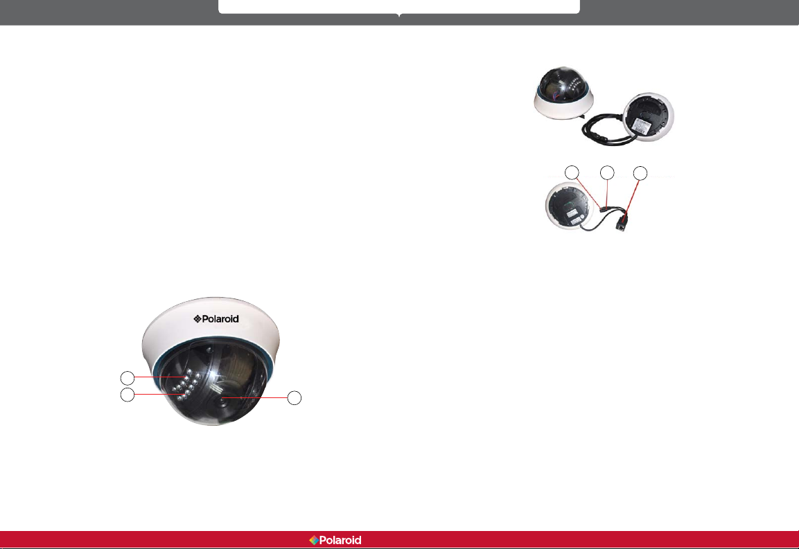
2.1 Product views
2
1
1. Light Sensor Holes: To detect the level of outside light and need for
infrared LED
1. Infrared LED
1. Lens: CMOS sensor with manual lens adjustment capability to adjust
the focus
Warning: Do not remove the plastic lens cover from the camera as it
may cause damage to the internal components of the camera.
3
2.2 Device interface
1
2
3
1. Reset button
2. Power adaptor
3. Ethernet port/L
LAN: RJ-45 10/100 Base-T
Power supply: DC5V/2A
RESET button: To reset the IP Camera settings back to the factory default
settings, press and hold the RESET button for 5 seconds.
3 Device installation
System conguration requirements for viewing multiple IP camera feeds:
CPU: 2.06 GHz or above
Memory: 512M or above
Network Card: 10M or above
Display Card: Microsoft DirectX 9 graphics device or above
Recommended Operating System: Windows XP/ Vista/Windows 7/Windows 8
Supports multiple web browsers: Internet Explorer/Firefox/Safari/Chrome, etc.
3.1 Hardware installation
When installing your IP Camera’s hardware, follow each step carefully in order
to ensure optimum camera operation. Take care with the IP camera’s installation
4 5
IP100 Manual
Page 4
environment; make sure the camera unit is mounted in an indoor environment,
protected from rain and other forms of moisture.
1. 1) IP Camera - Plug power adaptor into IP camera.
Note: Use only the power adaptor that comes with this product. DO NOT
attempt to substitute it with any other, as other adaptors may cause
damage to your unit.
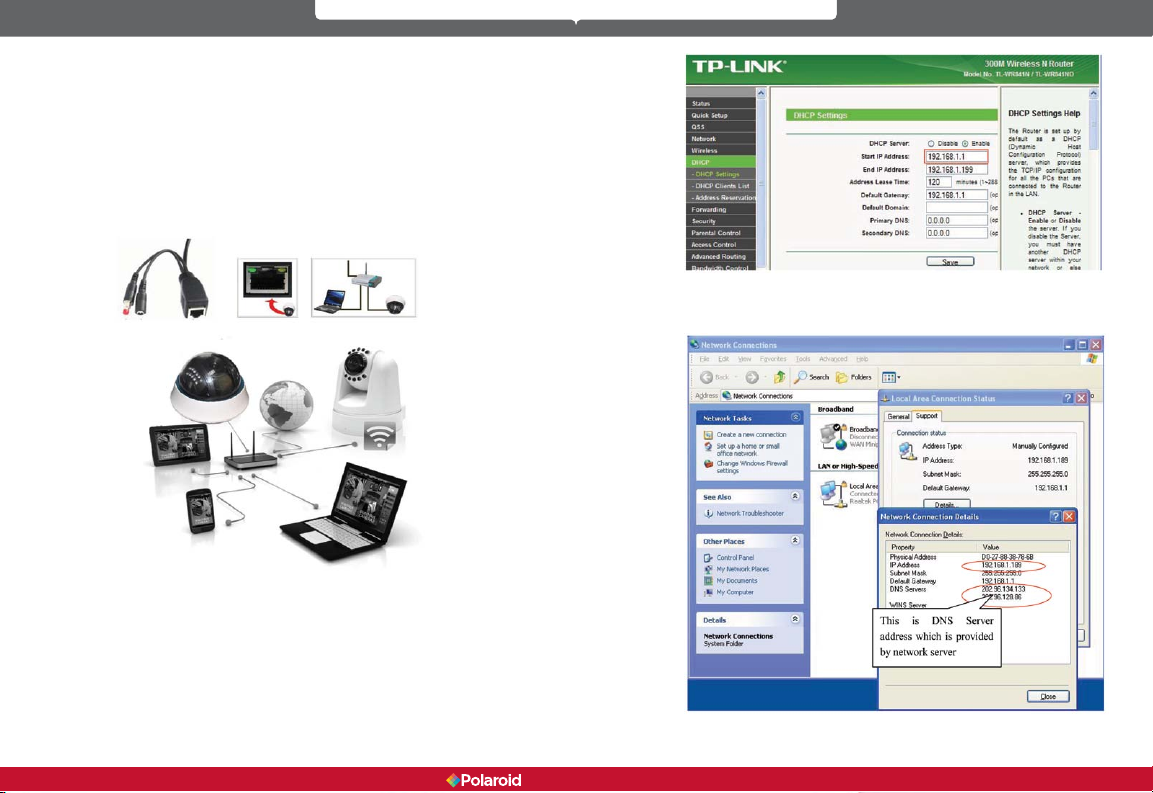
2. a) Connect the network cable into both the IP camera and the router. In
addition, make sure the IP camera is turned on and working properly. The
Subnet should be the same for the IP camera and your PC (on a LAN, you
can also use the network cable to connect the PC and IP camera)
3. As shown below, you can locate your computer’s IP address and DNS
server information
b) When you use the IP camera for the rst time, the IP address of the
IP camera will be obtained automatically. (Before using, make sure the
DHCP Server function in the LAN router has been opened,) The system
is very convenient for users as it is suitable for different LAN network
environments.
6 7
IP100 Manual
Page 5
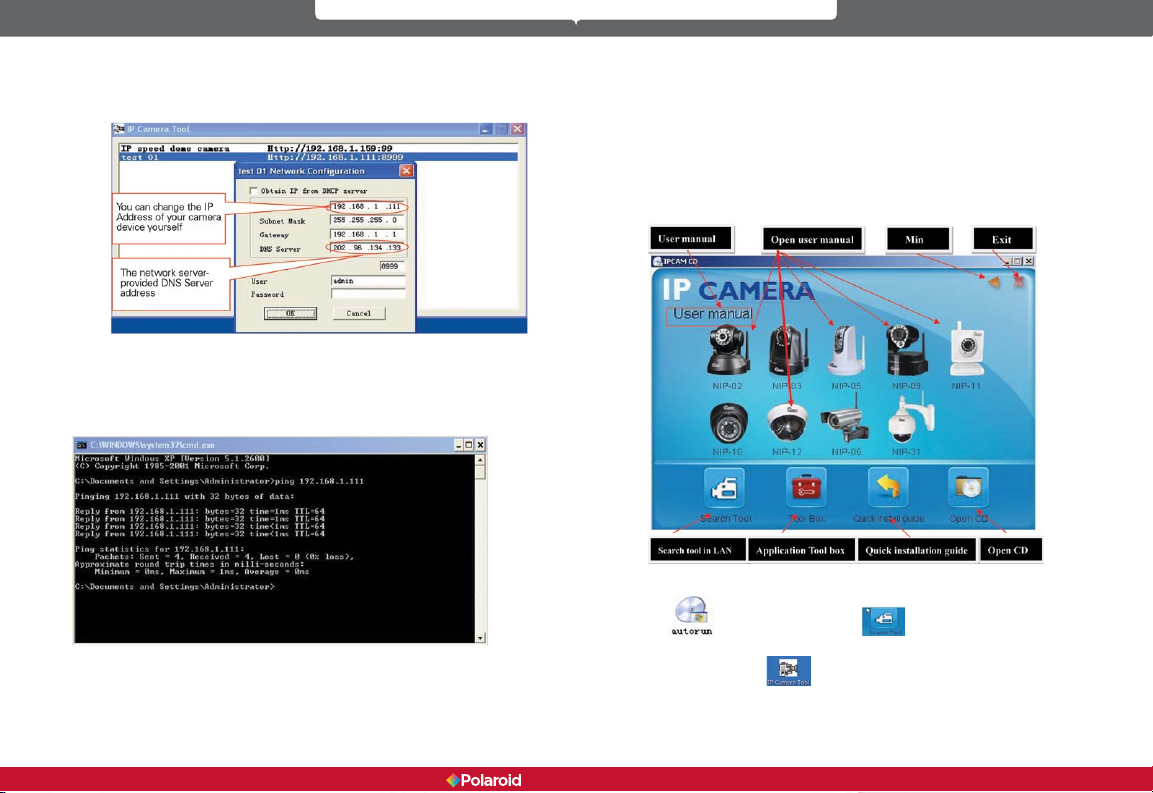
4. The camera’s IP Address can be changed, but it should always be the
same IP address as your computer’s subnet.
This is the DNS Server address which is provided by the network server.
In Windows, you can perform a ping test to make sure the IP camera is properly
connected and functioning. In the CMD window, which can be accessed
in Windows 7 by clinking on the Start icon, then on All Programs, then on
Accessories, and nally on Command Prompt, or by simply entering the letters
cmd in the search eld and pressing Enter, type or copy in: ping 192.168.1.111.
3.2 Software installation
Software installation:
The IP camera system software is very easy to install via the installation
program.
Insert the CD into your computer’s CD drive. The CD will automatically run the
software installation of the IP camera user interface (IPCamSetup). Note: If the
CD does not run automatically, you will need to access the CD drive and doubleclick on IPCamSetup. Follow the steps to install the software.
If the IP camera software interface does not appear, click “autorun.exe” on the
If you are able to ping the IP camera, that means the IP camera is working
properly and connected correctly.
8 9
CD.
your computer. You will then be able to see the “IP Camera Tool” icon on your
computer’s desktop
IP100 Manual
Then locate “search.exe” . Click and install the LAN Tool to
.
Page 6
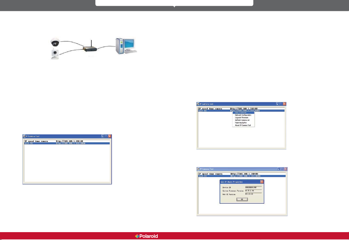
4 Viewing the IP camera on a LAN
4.1 Connecting via a LAN
4.2 Searching for and setting the device IP address
Before searching for your IP camera via the IP Camera Tool function:
1. Make sure the IP camera’s network cable is plugged in and that there is a
good connection with the network.
2. The router should have DHCP (Dynamic Host Conguration Protocol)
enabled because the IP camera’s factory setting is to automatically obtain
an IP address from the DHCP Server.
3. Turn on the IP camera and wait 20 seconds for it to boot up.
• Search IP camera
When you run the Search function in the IP Camera Tool, you will obtain a list
of the devices connected to the network. You will see your IP camera listed,
including the IP address, the port, and the camera name. If you are connected
via Wi-Fi, you will see the Wi-Fi IP address. See the below picture for an
example.
1. If the software has not found an appropriate IP camera server on your
LAN, you will see a message that indicates “No IP server found” and the
program will be automatically shut down;
2. If the software detected one or more cameras on your network, the IP
address of each camera will be listed on your computer screen. If you are
installing your rst camera, it will be the only one listed;
3. If the IP cameras installed on your LAN do not share the same subnet
with the monitoring PC, you will see a message that indicates “Subnet
does not match. Double-click to change.” Select the prompt and then
use the right-click function on your mouse to select and set the static IP
address of the camera to the same subnet as your PC on the LAN.
IP Camera Tool Options
To quickly access the six functions available with your IP camera, highlight
your IP camera on the list of devices, right-click on your mouse, and a box
will open that lists the options. They are as follows: Basic Properties, Network
Conguration, Upgrade Firmware, Refresh Camera List, Flush Arp Buffer, and
About IP Camera Tool (see Picture 12).
• Basic Properties – When you click on Basic Properties you will nd three
options: 1) Device ID, 2) System Firmware Version, 3) Web UI Version.
Note: The IP Camera Tool function can only be used to search for a camera
device’s IP address and port on a LAN. The tool cannot perform a search for a
device’s IP address and port on a WAN.
When searching or attempting to access your IP camera via the IP Camera Tool
function, you will receive one of three responses:
10 11
IP100 Manual
Page 7
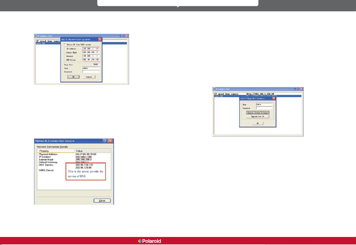
• Network Conguration – When you click on Network Conguration, a
box will open that allows you to congure you network settings. You can
congure the network as follows:
IP address: Fill in the assigned IP address, making sure it has the same
subnet as the gateway, the computer, and the router.
Subnet Mask: The default subnet mask of the equipment is:
255.255.255.0.
Gateway: Make sure it is in the same subnet as the computer’s IP
address.
The default Gateway address is 192.168.1.1.
DNS Server: The IP address of the Internet Service Provider (ISP).
This information can also found in the Network Connection Details
window(see Picture 15).
http Port: The default http port number is usually 80.
User: The default administrator user name is: admin.
Password: The password is: No password.
Obtain IP from DHCP server: If you click on (enable) “Obtain IP from
DHCP server” you will automatically be assigned a dynamic IP address
for your equipment if your gateway supports DHCP (most gateways
support DHCP). Make sure your router is connected and has the DHCP
function.
Note: If you receive a prompt that says, “Subnet does not match. Doubleclick to change,” reset the camera’s IP address, subnet mask, gateway, and
DNS server numbers.
• Upgrade Firmware
To upgrade the system rmware and the Web UI, start by entering your
correct user name and password. (The user should have administrative
authority.)
• Refresh Camera List
Refresh camera list manually.
• Flush Arp Buffer
When the cable network and wireless network of the device are both a
xed IP address, you may encounter an error. In the event you can locate
the camera IP address but are unable to open the camera web page, try
using the ush arp buffer to open.
• About IP Camera Tool
This option lets you check the software versions of the IP Camera Tool and
the ActiveX control.
4.3 IP Camera Login
From the list of devices in the IP Camera Tool window, double-click the IP
address of your IP camera. Internet Explorer will automatically open and display
the camera login page. Or, you can access the camera by typing the camera’s
12 13
IP100 Manual
Page 8
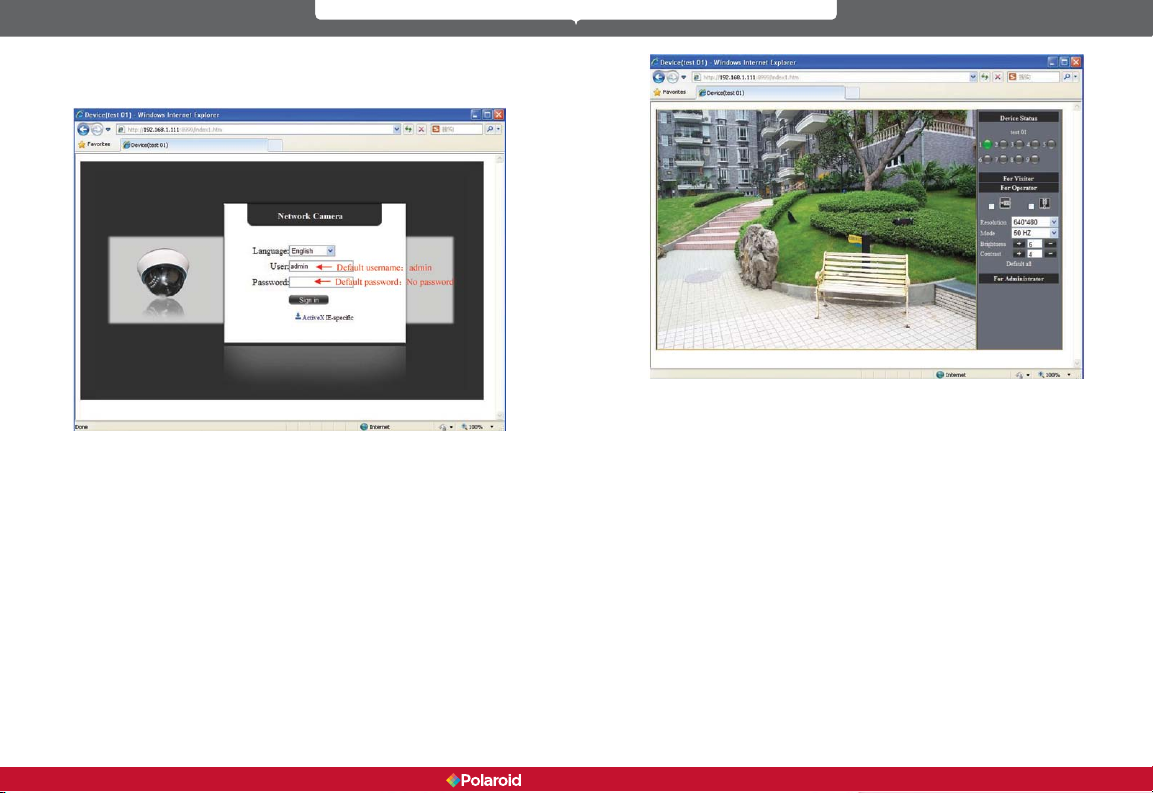
IP address directly into your browser. For example: http://192.168.1.111:8999.
(We recommend you use Internet Explorer as your browser due to its increased
functionality.)
At the camera’s login interface, enter the correct User name (default: admin)
and Password (default: no password). Click “Sign in” to enter the monitoring
page.
Once logged in you will see a drop-down list for Language. This allows you to
select your preferred operating language.
Users who are logged in correctly will be able to view images via the
video stream. Depending on a user’s level of administrative permission
(Administrator, Operator, or Visitor), the user will be able to operate the camera
according to the permissions available for their assigned administrative level.
In addition to Internet Explorer, users can access their system and view
streaming video through a variety of other browsers such as Safari, Firefox, or
Chrome.
14 15
IP100 Manual
Page 9
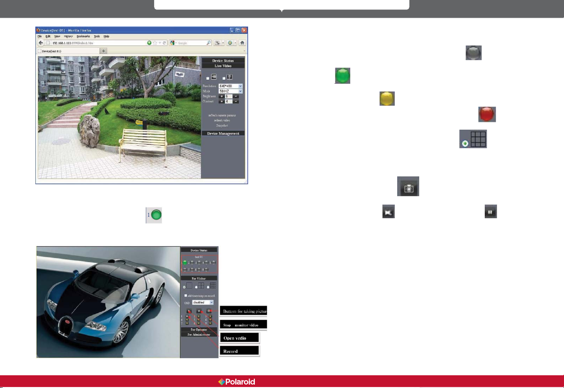
The Device Status indicator is located at the upper right corner of the screen.
This color-coded indicator shows the status of up to nine IP cameras.
• Gray – No device is connected to this channel
• Green – A device is connected to this channel and is functioning properly
.
4.4 IP camera operation
4.4.1 Visitor status users
If the status indicator for an IP camera
visitor has only the lowest level of operation which is mainly that of detection
(viewable only via Internet Explorer)
is lit, a user logged in as a
• Yellow – There is a device on this channel but it has failed to connect to
• Red – The device on this channel is in alarm status
If you want to detect all nine views, click this icon
OSD (On-screen display): Displays the date and time of the video. You can
disable the OSD function or choose a different color for this display.
Snapshot: Click on this icon
REC: Click on this icon
recording.
Note: The Record le name is: device Alias_ Current time. Avi
For example: IPCAM_20101011134442.Avi
This means the device name is IPCAM, its recording date is October 11, 2010,
and the recording end time is: 13:44:42.
When motion is detected the system will check and send a notication email
containing a snapshot.
The name of the picture that will be sent to your email inbox will appear like
this: device id (Alias) _ Current
time.jpg
4.4.2 Operator status users
Users who login with operator status, in addition to having access to all the
visitor-level functions, can also operate the Pan/Tilt feature and adjust the video
settings.
.
the main device
.
.
.
to take a snapshot of the live action.
to record (REC). Click this icon to stop
16 17
IP100 Manual
Page 10
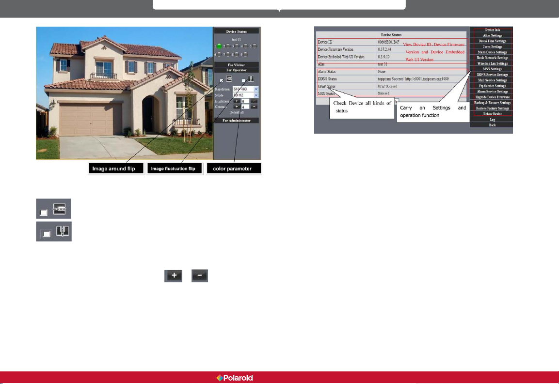
Direction control: Users can click on the arrows to change the direction of the
camera view.
Reverse image (up and down)
Resolution: The resolution can be set at up to 640 X 480 for VGA displays and up
to 320 X 240 for QVGA displays.
Work Mode: 50Hz/60Hz/Outdoor
Brightness and Contrast settings: Click on the
brightness and contrast settings.
4.4.3 Administrator status users
Users who login as administrator have authority to adjust all camera
settings. When you click on the “For Administrator” button, you will enter the
Administrator interface to all device settings.
Mirror image (right and left)
or to adjust the
Alias Settings: Lets you input a new name, or change an existing name for
your device.
Date &Time Settings: Date &Time Settings page.
Users Settings: This system allows up to eight user accounts. Each user’s
name, password and authorization level (Administrator, Operator, or Visitor) can
be congured here.
• Visitor: Authorizes you to only view.
• Operator: Authorizes you to control the direction of the IP camera and
set some of the parameters.
• Administrator: Authorizes you to perform advanced congurations of
the IP camera.
UPnP Status: If you access your IP camera remotely, make sure the UPnP
Status indicator shows “UPnP Succeed.”
Upgrade Device Firmware: Access this page if you want to upgrade your
device rmware and download system software updates. You must rst upgrade
the device rmware and then upgrade the device embedded Web UI (in that
order).
Restore Factory Settings: If you click on Restore Factory Settings, a prompt
will appear. Select OK and the camera will return to the original factory settings
and the device will reboot.
Reboot Device: If you click on Reboot the Device, a prompt will appear. Select
OK and the device will reboot.
Back: Clickon Back to return to monitoring mode.
5 Accessing the IP Camera via the Internet
5.1 How your IP camera connects to the Internet
18 19
IP100 Manual
Page 11
Related settings and IP camera login
1. To view your IP camera via the intenet, open a browser and enter your
external/public internet IP address into the address bar, then a colon sign
(:), and then enter the port number (for example, 192.168.1.10:8090). That
should bring up your camera’s login screen.
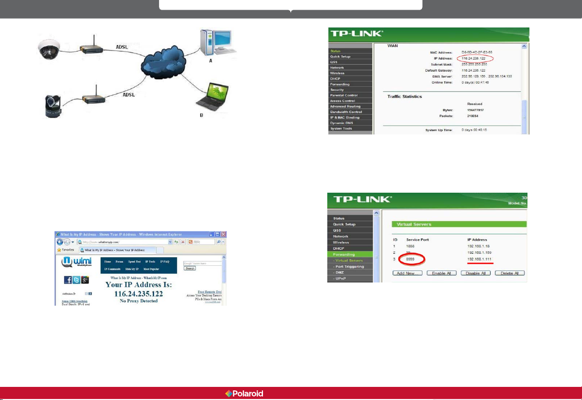
2. If you are using ADSL to access the Internet, you will need to obtain the IP
camera’s current WAN IP address or congured DDNS.
There are two ways for you to obtain the WAN (Internet, public) IP address:
1. Perform an online search to obtain the WAN IP address - It is very easy
for you to obtain your Internet (public) IP address if your IP camera and
computer are on the same subnet. Open your browser and type in: http://
www.whatismyip.com or http://www.myip.cn. It will bring up your WAN’S
IP address (see below).
2. Obtain from the router.
See the below diagram (Picture 27) for an example using a TP-LINK router.
According to the router manual, the router’s IP address is 192.168.1.1. To log
into the router, type 192.168.1.1 in your browser. You will see the status of the
router and also nd it’s WAN IP address. In this example, the WAN IP address is
116.24.235.122.
You will now be able to view the IP camera from the Internet. Type the correct
WAN IP address into your browser. For example: http:// 116.24.235.122:8999
Note: Make sure the Port’s UPnP is available. You can open UPNP as follows.
Go to the Settings page for your router (see full details in the user manual for
your router) to enable UPnP. Or, enable the virtual mapping function. Add the IP
address and service port for your device to the virtual mapping list.
Users can access the IP camera device via the Internet by inputting the IP
address. For example, http:// 116.24.235.122:8999
With DDNS (Dynamic DNS) service, you can use the server of your choice
and you will receive a dynamic IP address real-time that corresponds to that
server. Simply put, whenever the user is on the Internet, the user will get an IP
address. DDNS can ensure that a xed domain name can access a user’s device.
20 21
IP100 Manual
Page 12
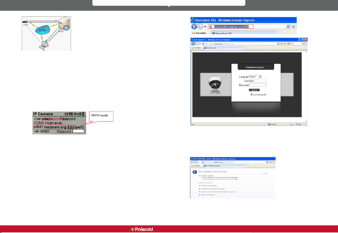
Our products have been congured for DDNS services. To use DDNS:
1. Log into the camera, click Network->DDNS Service Settings.
2. Select Third Party DDNS. This domain will be provided by a Third Party
DDNS provider, such as DynDNS, Oray, 3322, etc. (You must have an
account that must be registered on the web. To register your DDNS
account, go to: www.dyndns.org) Select your provider and complete your
DDNS user name, password and host name.
3. You must change the camera’s http port number from its default port
number of 80. You can change it, for example, to 100, 8090, etc. Click
“OK” and wait about 30 seconds for the camera to reboot. Make sure the
Subnet Mask, Gateway and DNS Server numbers are the same as the
ones on your router.
4. Set Port Forwarding in the router.
You need to ll in the DDNS and port. When you are logged on to the IP Camera
tool you can also nd the DDNS server settings via the Device Status screen.
For example: http://polaroidsafety.com:8999/ . The browser will take you to IP
camera login page.
Type the device’s User name and password in the login box to log into the
equipment.
If you type in the domain name but you are not able to open the IP camera in
the browser, you will receive an error message, as shown in the image below.
You must then check the status of the IP camera on the local area network,
conrm that UPnP is functioning and DDNS is successful.
22 23
IP100 Manual
Page 13
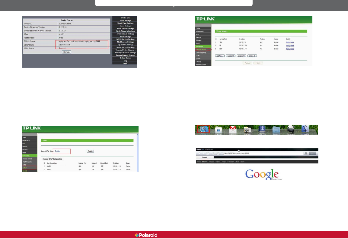
To use UPnP to set the port mapping function successfully, rst check to make
sure your router’s UPNP setting is on. If the UPnP function is unavailable, refer
to the user manual for the router for details on how to enable the router’s UPnP
setting.
If you use TP-LINK router, please refer to these instructions
In order to automatically allow your camera to utilize UPnP forwarding, input
your router’s IP address in your browser (for example, http://192.168.1.1). You
can locate the router’s IP address on the label on the router unit). Once logged
into your router’s setting page, click on Forwarding > UPnP, to make sure UPnP
is enabled (see diagram below).
Note: You must match the camera’s settings to those of your router. If you are
using a TP-LINK router, please refer to the router ’s user manual. Make sure
the “Obtain IP from DHCP Server” box is checked and the UPnP is enabled. To
manually set the port forwarding in your router, log into the router and select
the “Forwarding” option. Click the “Add New” button and provide the service
port number and IP address of the camera.
6 Accessing your IP camera via mobile devices - mobile
phone, iPad, etc.
There are two ways to access the IP camera through your mobile device. One is
to type the camera’s IP address directly in your browser (IP address or DDNS).
6.1 Inputting the IP address in your mobile device browser – See the
below examples of several popular mobile devices.
iPAD
Open the iPad browser (Safari)
Type in the IP camera’s IP address. For example: http://c0001.topipcam.org;8999
24 25
IP100 Manual
Page 14

At the login prompt enter your User name and password. The default User
name is: admin. There is no password.
Select your language from the drop down box and click the “Sign in” button.
If your login is successful you will be able to view live video.
Android phone:
From the device menu open your browser and type the IP camera’s IP address
26 27
IP100 Manual
Page 15

in the browser. For example: http://c0001.topipcam.org:8999
Type in the IP camera’s User name and password at the login interface and click
the “Sign in” button.
6.2 Install client-side software to access the IP camera
This IP camera system supports both client-side software and several thirdparty software providers. The following is the setup process for manufacturer
software (Android version).
2.4 Copy the ipcamera.apk onto the SD card.
2.5 Disconnect the device, locate the ipcamera.apk le in “File
Management” and run it.
2.6 The IP camera application will appear on your phone’s home screen
after you have successfully installed it.
Software operation steps:
Make sure you have Internet access via a Wi-Fi connection. In Google
Play, type “reecam” in the search eld to locate the Android reecam
application. Download and install the application.
1.
2. IP camera application installation steps:
You can get the installation application from the IP camera system
CD or you can download it from the following website:
https://play.google.com/store/search?q=reecam&c=apps
Choose the correct installation le: ipcamera.apk for Android version 1.6
or above application environment.
Note: Please make sure your mobile phone device can connect to the
Internet before installing this app.
2.1 Insert SD card into Android mobile phone.
2.2 Connect the cell phone to the computer via a USB data cable.
2.3 Choose the USB connection mode on your cell phone. In “My
Computer” you will see the SD driver.
28 29
IP100 Manual
Page 16

You can edit the camera, modify the camera conguration, and stop the
camera’s operation.
3. The IP camera setup process for iPhone/iPad Firmware requirements: Compatible with iPhone, iPod Touch, and iPad.
System requirements: Requires iOS 4.2 or above.
For each camera on the camera list, you can watch camera in real time,
control camera’s PTZ (pan-tilt-zoom), and switch the camera’s audio,
intercom, and video on and off.
You can download the authentic software
http://itunes.apple.com/cn/app/reecam/id479468959?mt=8
The software operation process is as follows:
from the App Store at:
30 31
IP100 Manual
Page 17

If the router your IP camera is connected to has the DHCP function, you can
check the box to “Obtain IP from DHCP Server.” If it does not, make sure the box
is unchecked so you can manually ll in the network parameters.
http Port: In most cases, you can leave this value as 80. However, if your Internet
Service Provider blocks this port, you may switch to another port number such
as 85, 8080, 8888, 9000, etc.
(The http Port number can range from 0 to 65535. If you have multiple cameras
or devices, make sure you use different http Port numbers for each piece of
equipment.)
a. In the IP Camera Tool, select your IP camera from the list and right-click on
your mouse to open the Network Conguration option. Enter your new http Port
number where indicated.
b. Click on the “For Administrator” button, then “Basic Network Settings” and
change the http Port number where indicated.
7 Other settings
7.1 Network Settings
7.11 Basic Network Settings
7.1.2 Wi-Fi Settings
Log into your wireless router and go to the Wireless Settings page, where you
will be able to locate your router’s SSID, Channel (under 10), and Encryption
Authentication information, as shown below:
32 33
IP100 Manual
Page 18

Log into your camera as Administrator, open the Wireless LAN Settings page,
and ll in every setting (using the same information as used for your router).
Upon completing these steps you can unplug the network cable, as wireless
network functionality is now enabled. See the example below.
7.1.3 Adhoc point-to-point wireless connection settings
1) Log into your camera as Administrator. Open the Basic Network Settings
interface, check the device status.
2) Click on the Wireless LAN Settings interface. In the Network Type dropdown
box, select Adhoc. You can dene the SSID, for example, 001. Wait for the
camera to reboot.
34 35
IP100 Manual
Page 19
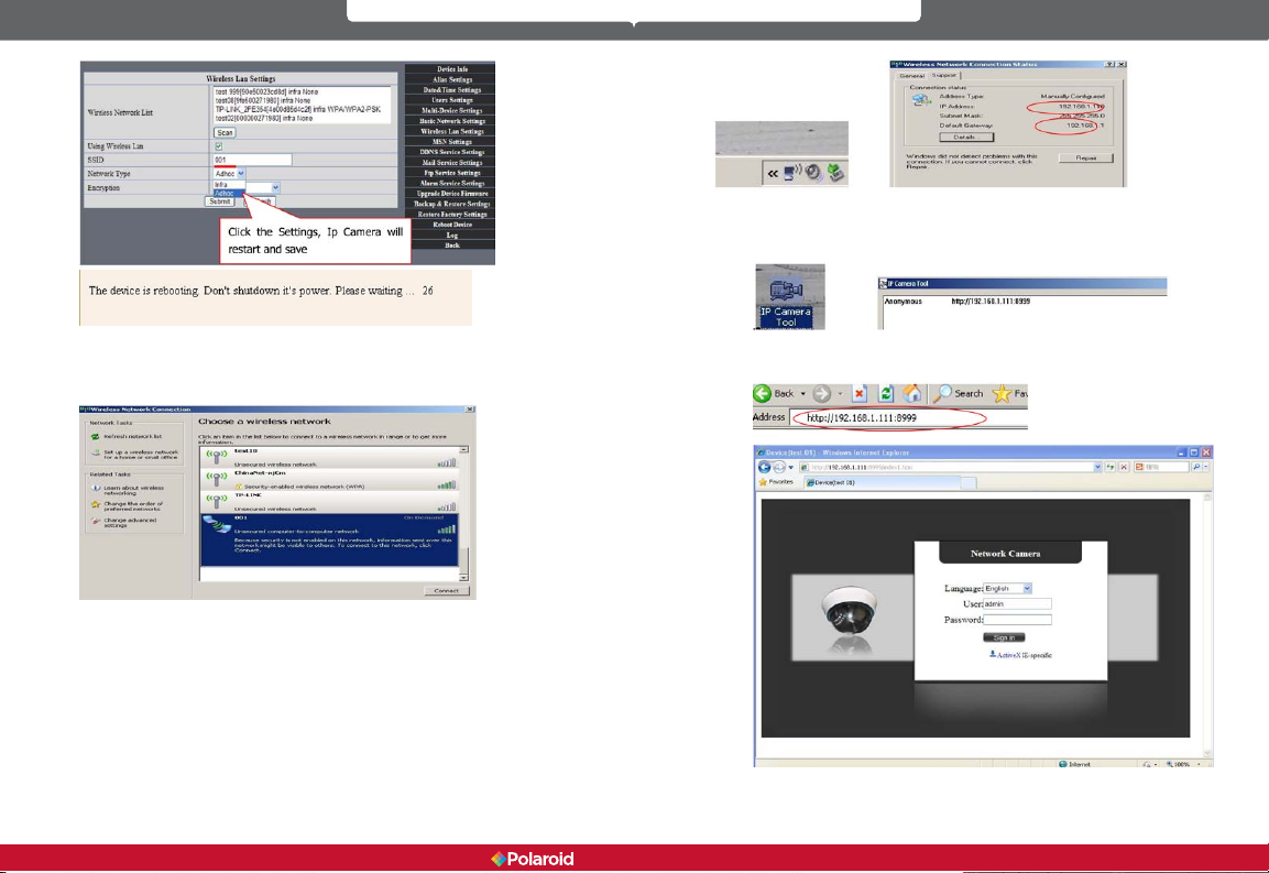
You can now use the IP Camera Tool or enter the camera’s IP address directly
into your browser in order to view.
1. Viewing via the IP Camera Tool
3) Unplug the network cable from the IP camera. Using a laptop or other
wireless device (Smart Phone, iPad, etc.) locate the SSID you dened in Step 2,
then click on it to connect.
After clicking on the wireless network of choice, check the connection status of
your IP camera.
Note: The IP address of your connected laptop must have the same subset
as your IP camera. If it does not, please reset the IP address of your laptop
manually.
36 37
2. Type the camera’s IP address into your browser. At the login interface
enter your User name and password.
Click on “Sign in” and you will be able to view.
IP100 Manual
Page 20

7.2 Multi-Device Settings
Adding cameras for viewing on the LAN On the Multi-Device Settings page, you can see all devices you have set up
on the local area network. The rst device is the default. The system software
will support up to nine IP camera devices for simultaneous monitoring. To add
another device, click on the next device (for example 2nd device), and then
double-click on the item in the “Device List in LAN” window. The Alias, Host,
and http Port information will ll in automatically. Enter the correct User name
and password then click the Add button. Follow these same steps to add more
cameras. When you have nished adding all your devices, click the Submit
button.
Adding cameras for Internet viewing First, make sure the camera added can access the Internet via the IP address or
DDNS domain. For example: http://219.133.200.166:9999 or http://IPcam.dyndns.
org:9999. You can enter the Host: 219.133.200.166, http port: 9999, or Host:
IPcam.dyndns.org, http port: 9999. Enter the correct User name and password
then click the Add button. Add more cameras in the same way.
7.3 MSN Settings
Go to the MSN Settings page. Enter your MSN User name and Password. You
can then add up to ten MSN buddies. Once submitted, they will appear on your
MSN Friends list. Click Submit and then Reboot Device (see picture below).
Note: Before setting MSN, set Port Forwarding (see DDNS Setting instructions
for details).
38 39
IP100 Manual
Page 21

First, login and click on Contacts. Select Add a Contact and then ll the contact’s
MSN account information (email address) in the Instant Messaging Address
space. Click Next, then Finish. You can obtain MSN accounts and passwords for
up to ten MSN friends.
From your IP camera’s MSN account page, open a chat dialogue box and type
in “URL?” After several seconds you will receive a reply with a remote access IP
40 41
IP100 Manual
Page 22

address for the camera in the chat box, as shown below :
You can type the IP address into your browser, and then view the IP camera (see
below).
Note: You should rst complete your MSN account information (email address)
in the IP Camera Tool.
7.4 DDNS Service Settings
DDNS Service: The IP camera system supports protocols from several DDNS
providers. These DDNS providers include: Dyndns.org, topipcam.org, Peanut
Shell, 3322.org.
To use DDNS, you must already have a registered account, User name,
Password, and Host (see section 5 for details). The DDNS Host is the DDNS
provider’s Domain Name.
7.4.1 Factory-provided DDNS
Each camera device includes factory-provided DDNS information, usually found
on the bottom of the device. The camera manufacturer gives every device a
unique DDNS address. For remote monitoring with the IP camera, users will
need to enter this DDNS IP address and port information into their browser.
Note: If you are unable to access the camera via the DDNS domain name and
UPnP, you must change the port mapping function on your router.
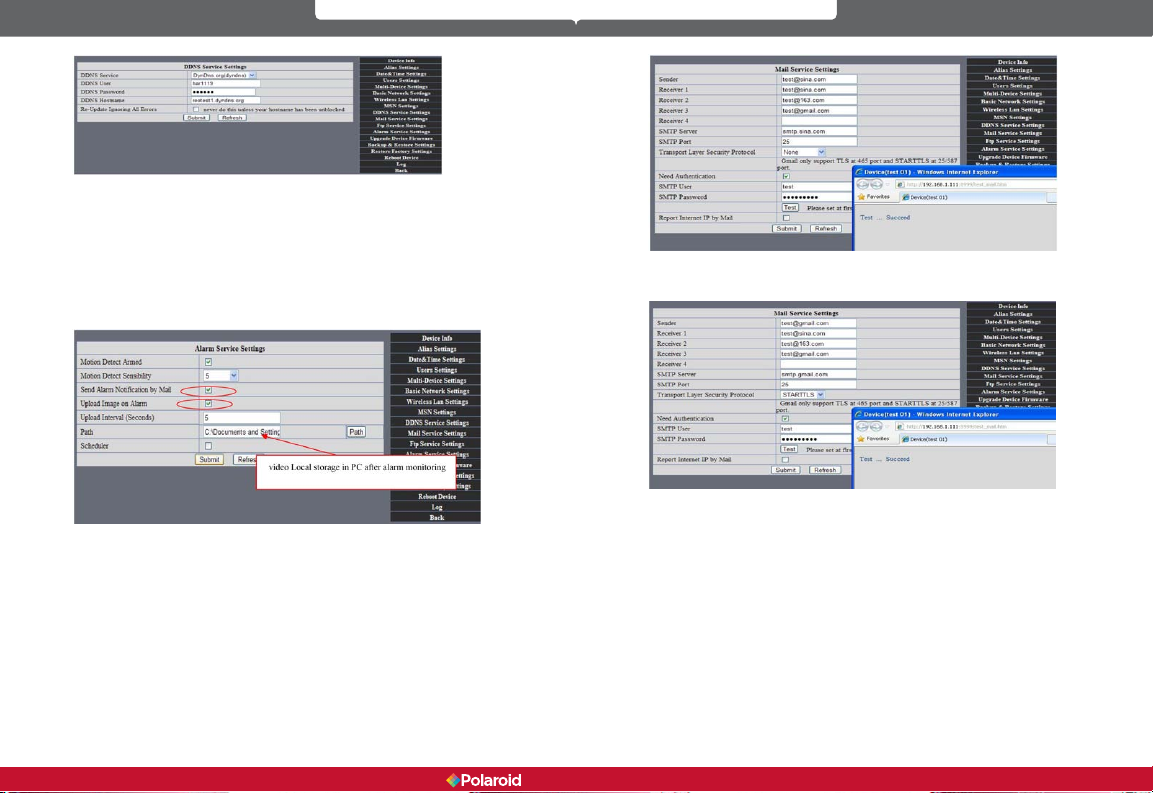
7.4.2 Third-party DDNS
In addition to factory-provided DDNS, users can also use third-party DDNS
providers, such as DynDNS (www.dyndns.com). To use DDNS, you must already
have a registered account, User name, Password, and Hostname. Provide this
information in the DDNS Service Settings box, as shown below.
42 43
IP100 Manual
Page 23
Note: Type the name of the third-party DDNS provider into your browser, and
it will be retained. If your camera’s default http Port number is 80, you must
change it to another number. For example: http://reotest1.dyndns.org:8999
7.5 Alarm, Mail and FTP Service Settings
Alarm Service Settings - You can congure the Alarm Service Settings to
receive and send emails based on specic IP camera events. You can receive an
Alarm Notication email containing images taken during an alarm phase.
In the Alarm Service Settings window, check the boxes for Send Alarm
Notication by Mail and Upload Image on Alarm to enable these features.
Gmail is also set the same way. Simply ll in the correct SMTP Sever address,
User name and Password.
Mail Service Settings – In this window you can congure your email
information for receiving IP camera system emails. You should ll in the
following information:
Sender: This IP camera device uses the sender mailbox to send emails.
Receiver: Indicates the email address to receive email from the Sender. You can
set up to 4 receiver mailboxes.
SMTP Server: The SMTP server for the sender mailbox.
Need Authentication: If the Sender mailbox needs authentication, check this box
and type in the
SMTP User name and Password.
Mail test: After conguring your Mail settings, and click Submit. After you have
done this, click on the Test button. The below image shows the Mail test results.
44 45
receive an error message after clicking on TEST, recheck the information you
entered to ensure it was all correct. Make the necessary corrections and click on
TEST again. Below are some of the error messages you may receive:
1. Cannot connect to server.
2. Network error. Please try later.
3. Server error.
4. Incorrect user or password.
5. Sender is denied by the server. You should re-authenticate the user and
try again.
6. Receiver is denied by the server. Your server’s anti-spam privacy software
could be causing a block.
7. Message is denied by the server. Your server’s anti-spam privacy software
could be causing a block.
8. Server does not support the authentication mode used by the device.
Report Internet IP by Mail: At the bottom of the Mail Service Settings window
there is a check box for Report Internet by IP Mail. If this box is checked, you will
IP100 Manual
If you
Page 24

receive the camera’s internet IP information via email (For example: The IPCAM
‘s URL is http://119.123.207.96:9002). Make sure the port is correctly mapped to
the router via the UPnP or Virtual Map function.
FTP Service Settings - If you have an FTP server on the LAN (IPCam. com) and
email ipcam , ll in the settings as shown below.
To create an FTP Server on the LAN -
1. Create an account, click Next.
2. Check off each type of permission for the account, click Next, then Finish
to save your settings.
3. Click on the Start button.
Continue through the steps to nish it:
46 47
IP100 Manual
Page 25

4. You can now use the IP camera’s FTP server account.
6. Click on the Test button to conrm setup and testing is successful. When
your IP camera alarms, images will be uploaded to your FTP server,
according to the settings of the main directory path (see below)
5. On the Ftp Service Settings window, ll in your FTP Server setting
information. Click on Submit when done.
48 49
FTP Server: The FTP server IP address.
FTP Port: The port is usually 21.
FTP Mode: This will support both standard (PORT) and passive(PASV)
modes.
Upload Image Now: Select this box and images will be uploaded.
Upload Interval: Lets you set the time interval (in seconds) you wish
between image uploads.
7.6 Motion Detection
Go to the Alarm Service Settings page to congure the Motion Detection (alarm)
function.
Motion Detect Armed – When you enable Motion Detection Armed, the
camera will sound an alarm when motion is detected and it will record the
incident. Should motion be detected, the Alarm Status will automatically switch
to Alarm Detect Alarm and perform the following:
- Send an email containing the alarm information.
IP100 Manual
Page 26
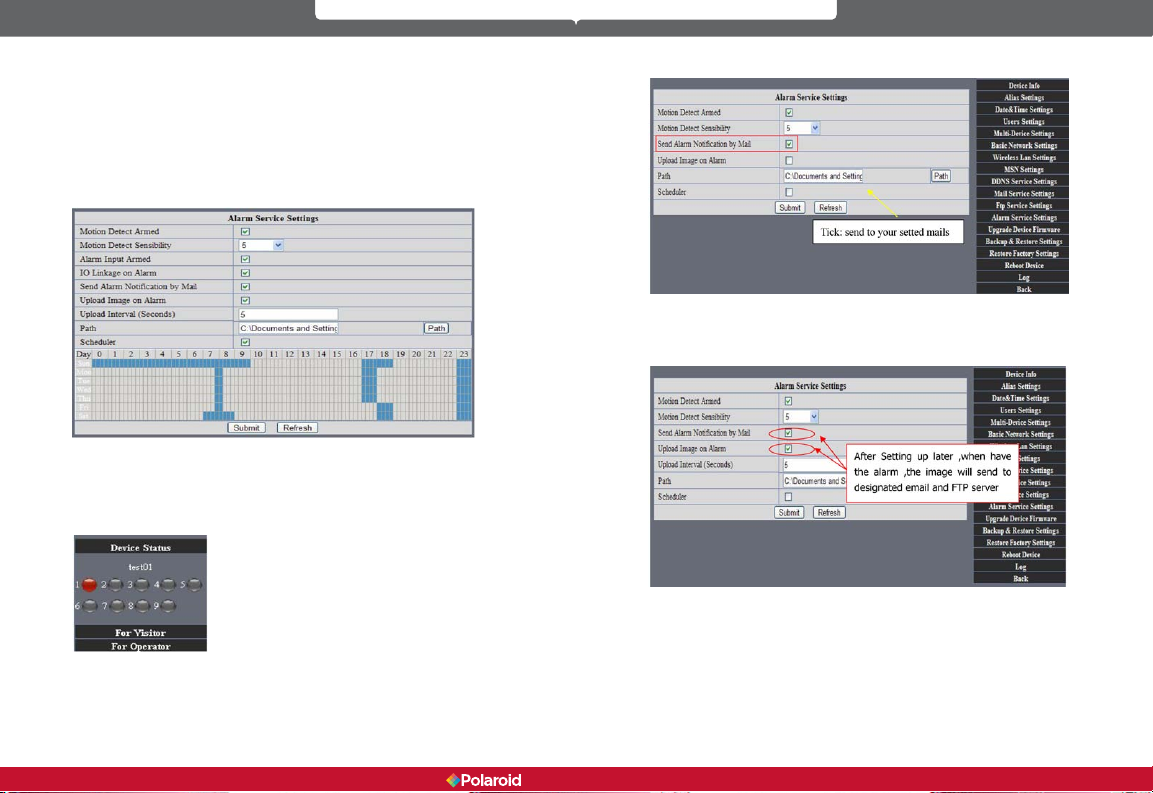
- Send images to the FTP server, according to the interval set for sending
images.
Alarm Scheduler – Using the scheduler, you decide when you want your
camera to alarm. You can set the alarm schedule according to days of the week,
hours in a day, and even by quarter hours. On the Scheduler, you can easily
click on the times you want the camera armed (the section selected will turn
blue to indicate your times). Click again to undo your schedule, and the eld will
return to its original gray (blank). If you do not use the scheduler, the camera
will alarm any time motion is detected.
Alarm Scheduler
Motion Detect Armed - When you enable Motion Detect Armed, the camera
can be triggered to send email alerts and record images. On the Device Status
indicator on the camera monitoring page, the green icon becomes red and an
alert will sound.
alarm is triggered. Make sure your Mail Service Settings are correct.
Upload Image on Alarm – When you check the “Upload Image on Alarm”
box, you enable the function of having all images sent to your FTP le once
the alarm is armed. You can set the intervals (in seconds) at which images are
uploaded.
REC automatically and save to PC - When you enable motion detection and
open the camera monitoring page on your computer, if an alarm is triggered,
the camera will automatically start to record (REC) for several seconds and save
the images to your computer.
Motion Detect Sensitivity - You can choose up to 10 motion sensitivity
settings. The higher the number, the higher the level of sensitivity.
Send Mail on Alarm – When you check on the “Send Mail on Alarm” box, you
enable this function and an email with a picture will automatically be sent if an
50 51
IP100 Manual
Page 27

7.7 Date & Time Settings
Click on the Date & Time Settings function to set the time and date for your
camera. Make sure you use the correct Clock Time Zone for your country and
region. If your IP camera is connected via the Internet, you can select Sync with
NTP Server and it will automatically check the time and date via the running
NTP Server. Or, you can select Sync with PC T ime to check the time and date on
your computer.
7.8 Upgrade Device Firmware
Firmware upgrade
The IP camera system has two kinds of programs. One is system rmware, and
the other is application rmware. Each can be upgraded separately.
7.9 Backup & Restore Settings
- Backup: You can back-up your established IP camera settings by clicking on the
Submit button. All settings will be stored in a Bin le.
- Restore: You can restore your IP Camera Tool and all settings. If you wish to
change camera settings to a new status, click Browse, select the new settings
from the Bin le, then click Submit.
8 Appendix
8.1 Register and Apply for DDNS Service
Before using DDNS management system for rst time, users must have a
registered account to manage the domain status.
Step1: In your browser, type http://www.dyndns.com and Create Account. Type
in the domain name: dyndns.com, then click Add.
52 53
IP100 Manual
Page 28
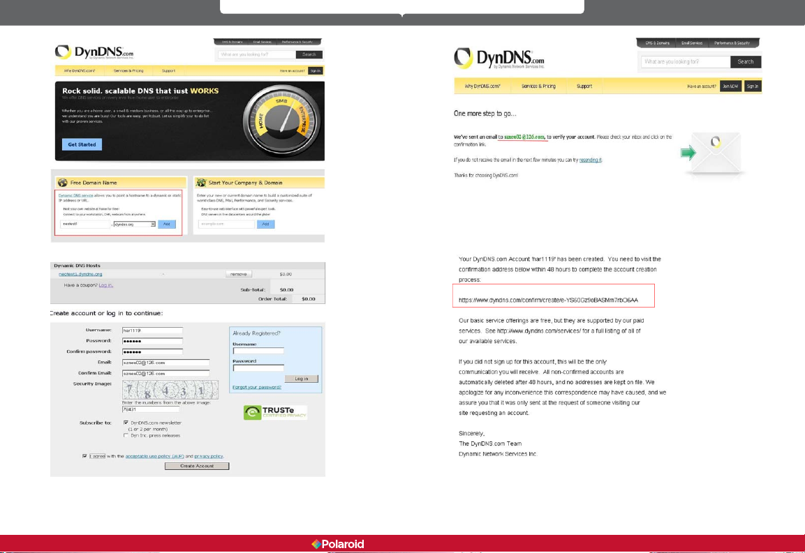
Step2: Enter your information. Click on Create Account.
Step3: Shortly, you will receive an email from DynDNS Support containing a
conrmation link
(for example, https://www.dyndns.com/conrm/create/eYS60Gz9oBASMm7rbO6AA).
54 55
IP100 Manual
Page 29
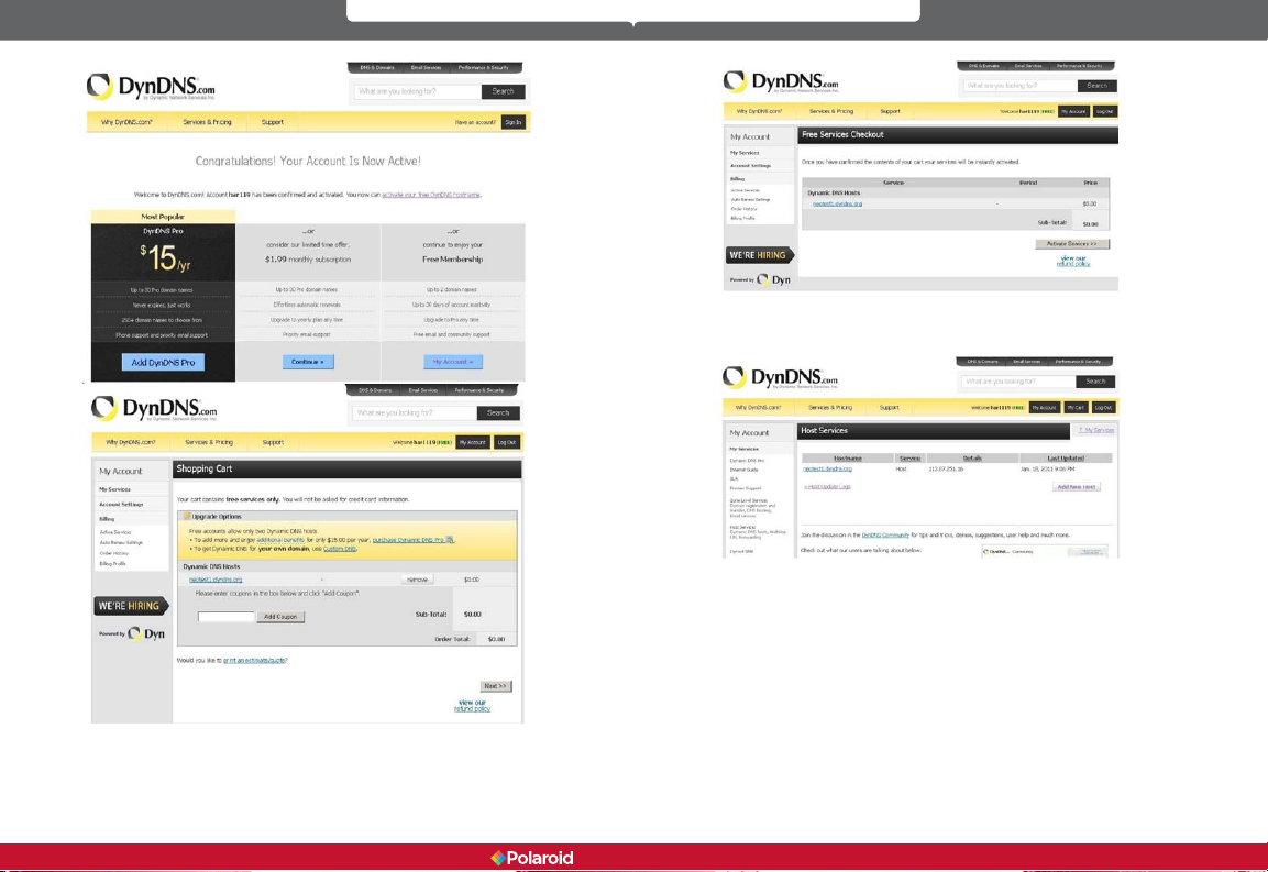
Step4: Click on the link to activate your domain name as shown below.
Step6: You should now have a Dynamic Domain Name (Figure below) which
you can use in the DDNS Service Settings function (see Section 7.4).
When you have properly completed registration for DDNS, you can ll in the
DDNS Service Settings information in the IP Camera Tool. When properly set,
the DDNS Status of your IP camera
will be shown as below.
56 57
IP100 Manual
Page 30
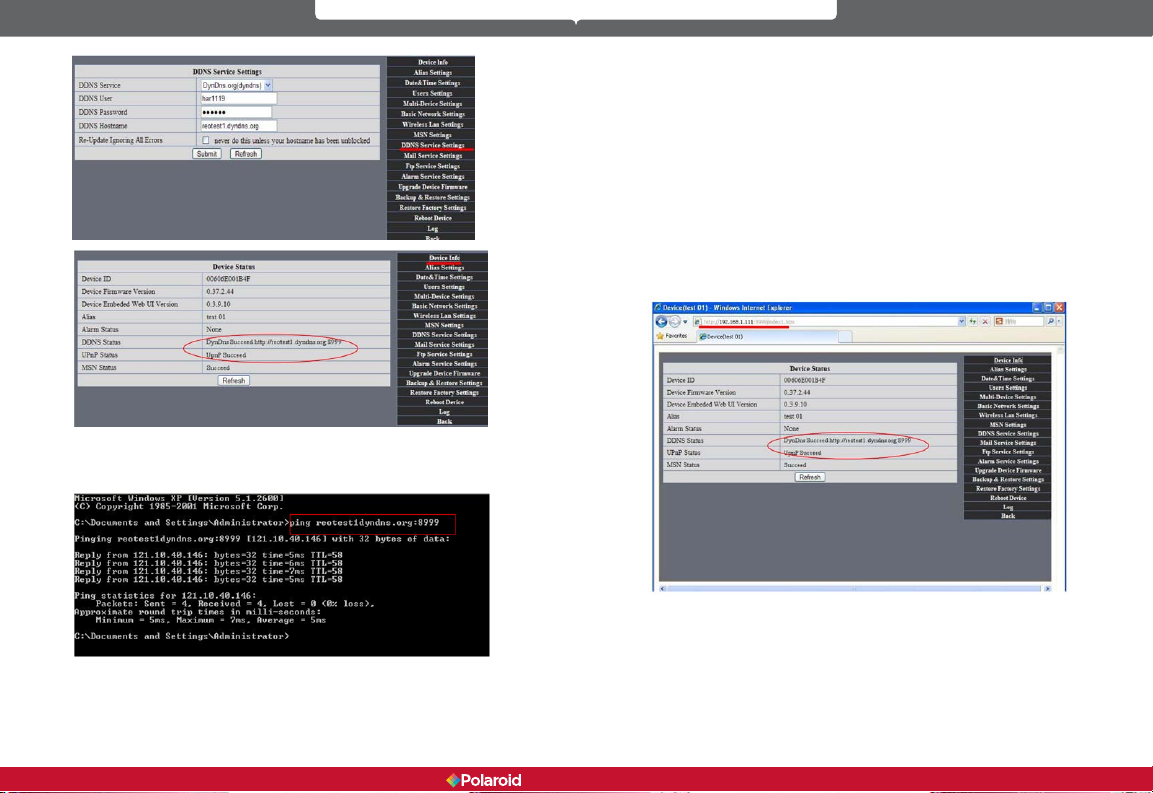
How to set DDNS online.
Follow these steps. Go to: Menu, Start, Run —> Type in CMD, click enter. This
will allow you to check your DDNS status. See below.
Using the PING command, the network response will provide you dynamic
domain name. This indicates the domain name works.
If the domain name update is not successful, it could be that the DDNS settings
are not correct or that the DDNS address conguration is incorrect.
8.2 IP Camera Abbreviations & Terminology
IPCAM: Refers to the IP Camera Tool, used for IP camera control settings
User Name: user
Password: password
Pri: Access level priority (1: visitor, 2: operator, 3: Administrator)
Resolution: Image resolution (8: 320X240 QVGA, 32: 640X480 VGA)
Rate: Image transmission speed and scope 0-23
Brightness: Brightness, 0~255
Contrast: Contrast, 0~6
Mode: Mode 50Hz/60Hz, outdoor
Flip: Rotation
Keyboard shortcuts: 0: Reset to straight, 1: Flip up or down, 2: Mirror, 3: Both
8.2.1 Stream Video through Media Player
VLC media player can broadcast your IP camera view real-time and stream live
video data.
(Language settings: /videostream.asf?user=&pwd=&resolution=&rate=)
From the following picture, we see that the IP camera’s local IP address is:
http://192.168.1.111:8999
TWAN IP Address is: http://reotest1.dyndns.org:8999:we can input the IPcam’s IP
address to open via the media player:
58 59
IP100 Manual
Page 31
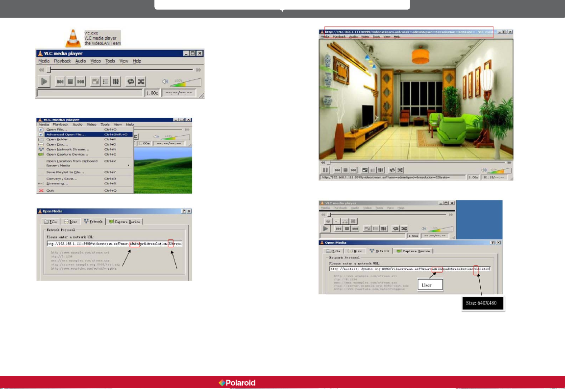
The “CLC media player” open play position:
LAN play address;
Open the Internet play position:
As shown in the following picture, It can see the ip camera send video
streaming format
8.3 Frequently Asked Questions
Note:
1. If you encounter any difculties during either the setup or running of
your IP Security Camera system, you should rst check all the network
connections to make sure everything is properly connected.
60 61
IP100 Manual
Page 32

2. Check the indicator status of your network server, hub, exchange, and
network card.
8.3.1 I have forgotten the administrator username and/or password.
To reset the administrator User name and password, Press and hold down the
RESET BUTTON for 5 seconds. Release the power button and the username
and password will be reset to the factory default administrator User name and
password.
Default administrator User name: admin
Default administrator password: No password
8.3.2 IP address conguration
To check if the IP address of the IP camera and your computer share the same
subnet, click: My Computer > Control Panel > Network & Dial-up Connections
> LAN > Attributes > Internet Protocols (TCP/IP), and check the IP address and
Subnet Mask. Make sure the camera and computer are in the same subnet
when conguring the IP camera’s IP address manually.
8.3.3 Network Conguration
Check to ensure that your http Server software is congured and running
properly. If you are running rewall software make sure it allows inbound
connections to port 80. Also, if you are using a cable/DSL router, make sure you
have set up port forwarding properly. (Consult your router’s documentation for
more information.) If none of these seems to be the problem, it is also possible
your ISP is blocking inbound connections to port 80. Many ISPs have done this
because of internet worms such as Code Red. If this is the case, you will have to
setup your http Server on an alternate port, such as 8080.
8.3.4 I cannot see what my camera is monitoring
There are four reasons why you might not be able to view the images your
camera is sending:
1. If the DirectX function is not installed, color images may not display
properly. Please install DirectX, open the start menu and input the
command.
If these features do not work, there may be connection issues or the
hardware is not reading it properly.
2. You may have a hardware issue, for example, it cannot support the card
or enable images.
3. Your rewall or antivirus software may be blocking the camera. Try
closing your antivirus software or rewall, or make the camera a “trusted
device” in the rewall and antivirus settings.
4. ActiveX controller may not be installed correctly. If there’s no image the
rst time you use the camera there may be an installation error. Follow
these steps:
1. Install the “IP Camera Tool” and ActiveX control at the same time.
2. Install ActiveX control, maintaining the Internet Explorer security
settings.
8.3.5 Network bandwidth problems
The image frame rate is subject to the following factors: 1) network bandwidth,
2) computer performance, including network environment and display
preference settings (brightness, theme, etc.), 3) the number of visitors accessing
at one time (too many visitors can slow down the image frame rate), 4) choice
of switch or hub for access (use of a switch rather than a hub is recommended
for multiple IP cameras).
Devices using MJPEG compression require a lot of network bandwidth. If there
is not enough, it will lead to slower browsing. Typical video settings require
network bandwidth as noted below:
640x480@30fps: 4.0 Megabits~5.0 Megabits
320x240@30fps: 1.2 Megabits~1.6 Megabits
8.3.6 Why am I getting a “Failure to connect to the device” prompt?
This can happen when you have multiple cameras. Enter the Multi-Device
Settings page (log in as administrator) to make sure the Device settings are
correct. When one of the multiple cameras is disconnected, the indicator color
changes to yellow
and this prompt appears.
In DirectX, DirectDraw, Direct3D and AGP Texture should be enabled.
62 63
IP100 Manual
Page 33

8.3.7 Why can’t my IP camera be accessed over the internet?
There could be several reasons:
1. The ActiveX controller is not properly installed (see details in Section
5.1.4).
2. Your rewall or antivirus software is blocking the port. Change the port
number and retry.
3. Port mapping is incorrect. You can do port mapping one of two ways:
1. Enter the settings page of the router the IP camera is connected to, to
enable the UPnP function. Enter the IP camera “UPnP Settings” to enable
UPnP, and make sure the status is “UPnP success”.
2. If your router has a virtual mapping function, enter the router settings
page, add the IP camera’s IP address and port to the virtual map list.
When using ADSL, the IP address is dynamic. You should set the DDNS
(see details in Section 5.1) and also make sure the status is “port
mapping success”.
8.4 Solutions to common operating problems
The IP Camera Tool cannot locate the camera’s IP address.
This assumes the camera is not broken.
First, check the Ethernet cable and power cable to make sure everything is
properly connected according to international standards. Another issue could
be the computer’s operating system may not be the level required to run the IP
Camera system.
Second, check to make sure the power is on and that the power indicator light is
on. If it is on, then check the yellow light on the RJ45 port (power indicator light)
and the green light (network indicator light). If these lights are both on, the
power supply is functioning normally.
Third, check to make sure your rewall and antivirus software is not blocking
the camera. Firewalls often block unrecognized data, so if the rewall is running,
it may be blocking the IP Camera Tool’s ability to nd the device. We recommend
you temporarily shut down the rewall and antivirus software before searching,
or, set the camera as a “Trusted Device” in your rewall and antivirus settings.
Why am I getting a blank screen from my camera?
1. Check to see if you are using the wrong power adaptor. Please use the
one that came with your IP Camera system.
2. Close antivirus software.
Why can’t I login to my camera over the Internet?
1. Check to make sure “DDNS success” is set.
2. Make sure the current IP camera’s port number is the same as your
router’s port number. These two numbers should be the same.
Why can’t I see what my camera is monitoring?
1. Reason: Unable to connect with the network
Solution: Make sure you have a network connection and that there are no
cable failures or computer viruses that could be causing network failure.
2. Reason: The IP address is being used by another device
Solution: Choose automatic gain
3. Reason: The IP address is located within a different subnet
Solution: Check the IP camera’s IP address, subnet mask address, and
gateway settings.
4. Reason: Web port has been changed
Solution: Contact your network administrator to obtain the correct port
information.
5. Reason: Unknown
Solution: Press reset button to restore factory defaults, then reboot. The
system default for obtaining an IP address is automatic, the subnet mask
is 255.255.255.0
8.5 Default Settings
Default network settings
IP address: dynamic obtain
Subnet mask: 255.255.255.0
Gateway: dynamic obtain
DDNS: Factory provide- Username and password
Default administrator username: admin
Default administrator password: No password
8.6 Technical Settings
ITEM - IP CAM (NIP-02BGPWA2)
Image Sensor –
Image sensor - 1/5” Color CMOS Sensor
Display - 640 x 480 (300k Pixels)
Lens - f: 3.6mm, F: 2.4 (IR Lens)
Mini.illumination - 0.5 Lux
Lens -
Lens Type - Glass Lens
64 65
IP100 Manual
Page 34

Viewing Angle – 60-degree
Audio – Microphone - No head
Domain name – Server - MSN server/DDNS server
Video -
Image Compression - MJPEG
Image Frame Rate - 15 FPS (VGA), 30FPS (QVGA)
Resolution - 640 x 480(VGA), 320 x 240(QVGA)
Flip Mirror Images - Vertical/Horizontal
Mode - 50Hz, 60Hz, or Outdoor
Video Parameters - Brightness, Contrast
Communication -
Ethernet - One 10/100Mbps RJ-45
Supported Protocol - http/DHCP/IP/TCP/UDP/FTP/SMTP/DDNS/PPPoE/
UPnP
Mobile phone monitor - Support iPhone/iPad/3G Phone/smartphone
Wireless Standard - IEEE 802.11b/g
Wireless Standard - 802.11b:11Mbps (max.) 802.11g: 54Mbps (max.)
Wireless Security - 64/128-bit WEP Encryption
Physical -
Pan/Tilt Angle - Fixed
Infrared Light - 22 IR LEDs, night visibility up to 20 meters
Product size – 130mm x 130mm x 75mm
Gross Weight - 498g/17.5 oz)
Net Weight - 291.4g/ 10.2 oz
Power -
Specication - DC 5V/2.5A 1.8 meter
Power Consumption - 5 watts
Environment -
Operating Temperature - 0°~55°C (14°~130°F)
Operating Humidity - 20% ~ 85% non-condensing
Storage Temperature -10° ~ 60°C (50° ~ 140°F)
Storage Humidity - 0% ~ 90% non-condensing
PC Requirements -
CPU - 2.0GHz or above (recommended 3.0GHz)
Memory Size - 512MB or above (recommended 1.0GB)
Display card - 64M or above
Supported OS - Microsoft Windows XP/Vista/Windows7
Supported Browsers – Internet Explorer/Firefox/Google Chrome
Certication - CE, FCC, RoHS
Warranty - Limited 1-year warranty
PLR IP Holdings, LLC, its licensees and afliates, fully support all electronic waste initiatives. As responsible stewards of the environment,
and to avoid violating established laws, you should properly dispose of this product in compliance with all applicable regulations,
directives or other governances in the area where you reside. Please check with local authorities or the retailer where you purchased this
product to determine a location where you can appropriately dispose of the product.
You may also go to www.polaroid.com to learn more about the specic laws in your area to locate a collection facility near your home.
If your electronic device has internal memory on which personal or other condential data may be stored, you may want to perform a
data sanitization process before you dispose of your device to assure another party cannot access you personal data. Data sanitization
varies by the type of product and its software, and you may want to research the best sanitization process for your device before
disposal. You may also check with your local recycling facility to determine their data sanitization procedures during the recycling process.
Polaroid, Polaroid & Pixel, and Polaroid Classic Border Logo are trademarks of PLR IP Holdings, LLC, used under license. All other
trademarks are the property of the respective owner, who has not sponsored, endorsed or approved this product. PLR IP Holdings, LLC
does not manufacture this product or provide any Manufacturer’s Warranty or support.
Distributed by:
C&A Licensing, LLC
2 Bergen Turnpike
Ridgeeld Park, NJ 07660 USA
© 2012 All Rights Reserved
MADE IN CHINA
More information and resources are available for download at:
www.polaroidsafety.com.
66 67
IP100 Manual
Instantly recognizable. Instantly
reassuring. The Polaroid Classic Border
lets you know you’ve purchased a product
that exemplifies the best qualities of our
brand and that contributes to our rich
heritage of quality and innovation.
 Loading...