

Page 1
Page 2

i
Table of contents
1 Hardware installation
Overview 1-1
Before you begin 1-4
Installation 1-6
Operating the scanner 1-11
Miscellaneous 1-14
2 Software Installation
Overview 2-1
Installing the CS-600 PtP and related software 2-2
Installing the Microscan Utility 2-5
Installing OmniPage Direct 2-8
Installing Print to Press Software 2-8
Page 3

ii
3 Reference
Overview 3-1
The CS-600 PtP 3-4
Preview window 3-6
Scanner menu 3-8
View menu 3-10
Preferences menu 3-15
Tool buttons 3-28
Settings window 3-36
Image-Enhancement tools 3-48
Information window 3-82
Scan Job window 3-88
4 Exporting separation files
Overview 4-1
Using PolaSharp 4-4
Using other Photoshop filters and tools 4-9
Exporting the CMYK file 4-10
Thumbnail preview images 4-14
Creating a For Position Only (FPO) image 4-14
Selecting the ink standard 4-14
Selecting the paper 4-15
Selecting the press 4-16
Customizing press settings 4-17
Using setups 4-20
Creating the separation file 4-23
Appendix A: Dot Gain A-1
Appendix B: Polaroid Film B-1
Appendix C: Color Transformation C-1
License Agreements L-1
Page 4

Overview
This section provides information on installing the hardware
for your scanner. An outline is provided on the following
page to guide you through the various stages of hardware
installation.
1 Hardware installation
1-1
Page 5

To do this See the section
1 Go through preliminaries Before you begin
• Unpack the scanner
• Check requirements
• Check voltage
2 Install the scanner Installation
• Release the carriage
• Set up cabling
• Check the SCSI ID
3 Operate the scanner Operating the scanner
• Perform power-on test
• Positioning a document
• Scanning a thick document
• Using scanner accessories
4 Perform other tasks Miscellaneous
• To return the scanner
• Lock the carriage
• Replace the scanning lamp
1-2
Page 6

Checklist for This is a quick rundown of things you need to do and look
hardware installation out for to install your hardware properly.
• Unpack your scanner and read the Packing List first to deter-
mine if you have everything you need. If not, call Polaroid
Technical Assistance. See section below.
• Check system requirements and scanner voltage. See page 1-5.
• As the first step to installation, release the carriage lock. See
page 1-6.
• After unlocking the carriage, set up cabling. Depending on
your installation, you may or may not need terminators. See
pages 1-7 to 1-9.
• Check the scanner’s SCSI ID. If it needs to be changed, set the
ID according to procedures outlined on pages 1-9 to 1-10.
• To operate the scanner, turn on the power button at the back
of the unit. The POWER and READY indicators on the front
should light up and stay on solidly. If they don’t stop blinking, there may be a hardware problem with your scanner. At
this time, the fluorescent lamp inside the scanner should be on
as well. See page 1-11.
• For information on how to position a document for scanning
and the use of scanner accessories, see pages. 1-12 to 1-13.
• If you need to return the scanner for whatever reason, lock
the scanner carriage, then follow scanner-return procedures.
See pages 1-14 to 1-15. If the scanner lamp needs to be
replaced, see page 1-16.
Technical assistance
Call toll-free within the U.S.A.: 1-800-225-1618, Monday
through Friday, 8 a.m. to 8 p.m. (Eastern time). Or, write to
the Polaroid Resource Center, 201 Burlington Road, Bedford,
MA 01730. In Canada, call toll-free: 1-800-268-6970.
Outside North America, please contact the Polaroid office
nearest you.
Hardware installation 1-3
Page 7
Before You Begin
• Unpack the scanner
• Check requirements
• Check the voltage
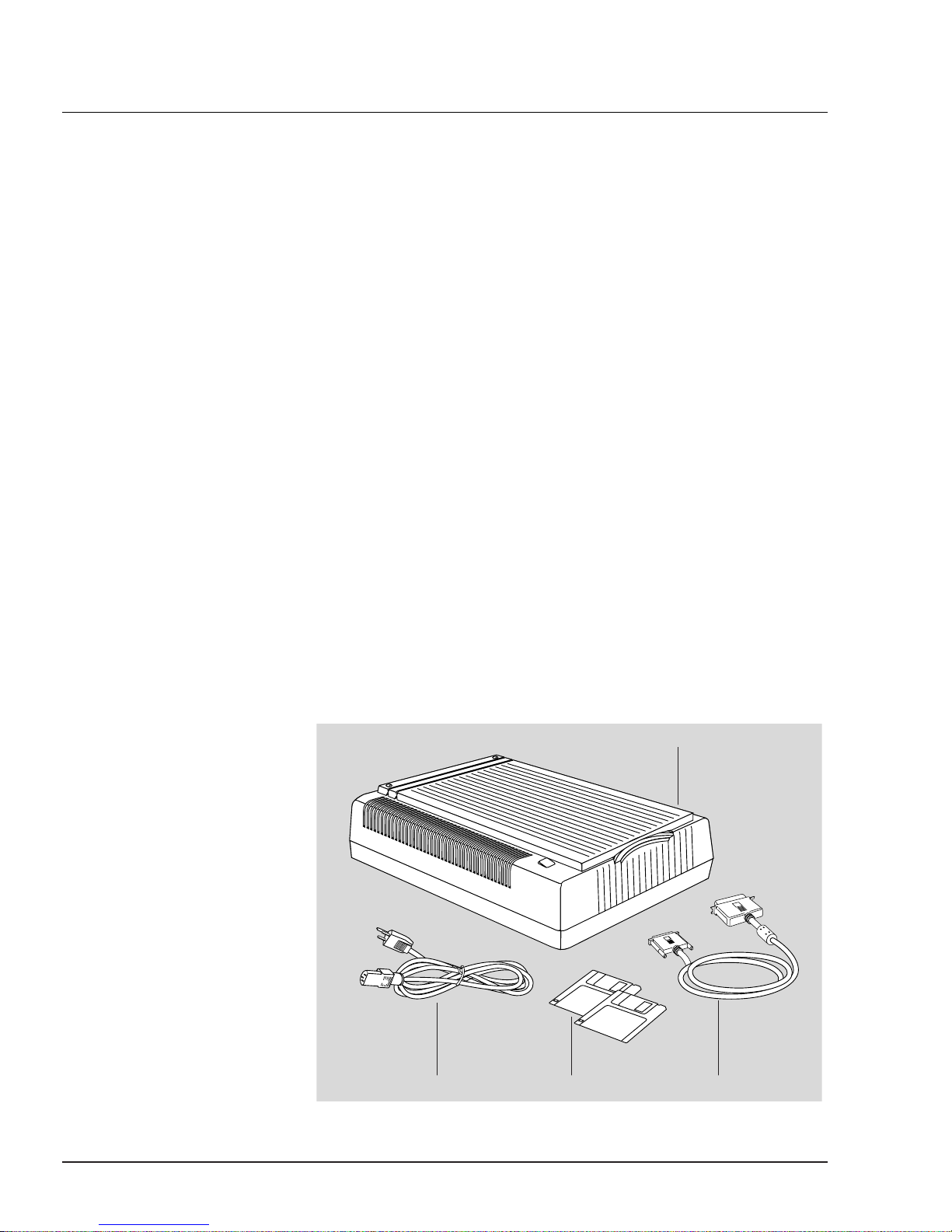
Unpacking the scanner Remove the scanner from the box, and save the box and
packing materials in case you need to ship the scanner again.
Upon opening the scanner box, you will see a Packing List
that lists both hardware and software components of your
scanner package, as well as the part numbers for those components.
If any component is missing, call Polaroid Technical
Assistance (see page 1-3) and provide information on the
missing component and part number. Keep the Packing List
for your reference in case you need to order a component in
the future.
Note:
If you need to return the scanner for any repairs, the
scanner must be packed in the original box in which it came.
Otherwise, Polaroid will not be responsible for any damage
that may be sustained during shipping to or from Polaroid.
You may be charged for a new box.
1-4
scanner
power
cord
software
diskettes
SCSI
cable
Page 8
Requirements • Macintosh II series, Centris, Quadra, or Power Macintosh
• System 7.0 or later
• SCSI system cable
• 12MB RAM (16MB minimum and 24MB recommended on
Power Macintosh)
• 40MB hard disk (200MB recommended); at least 20MB free
• Color monitor; color display card; laser printer (recommended)
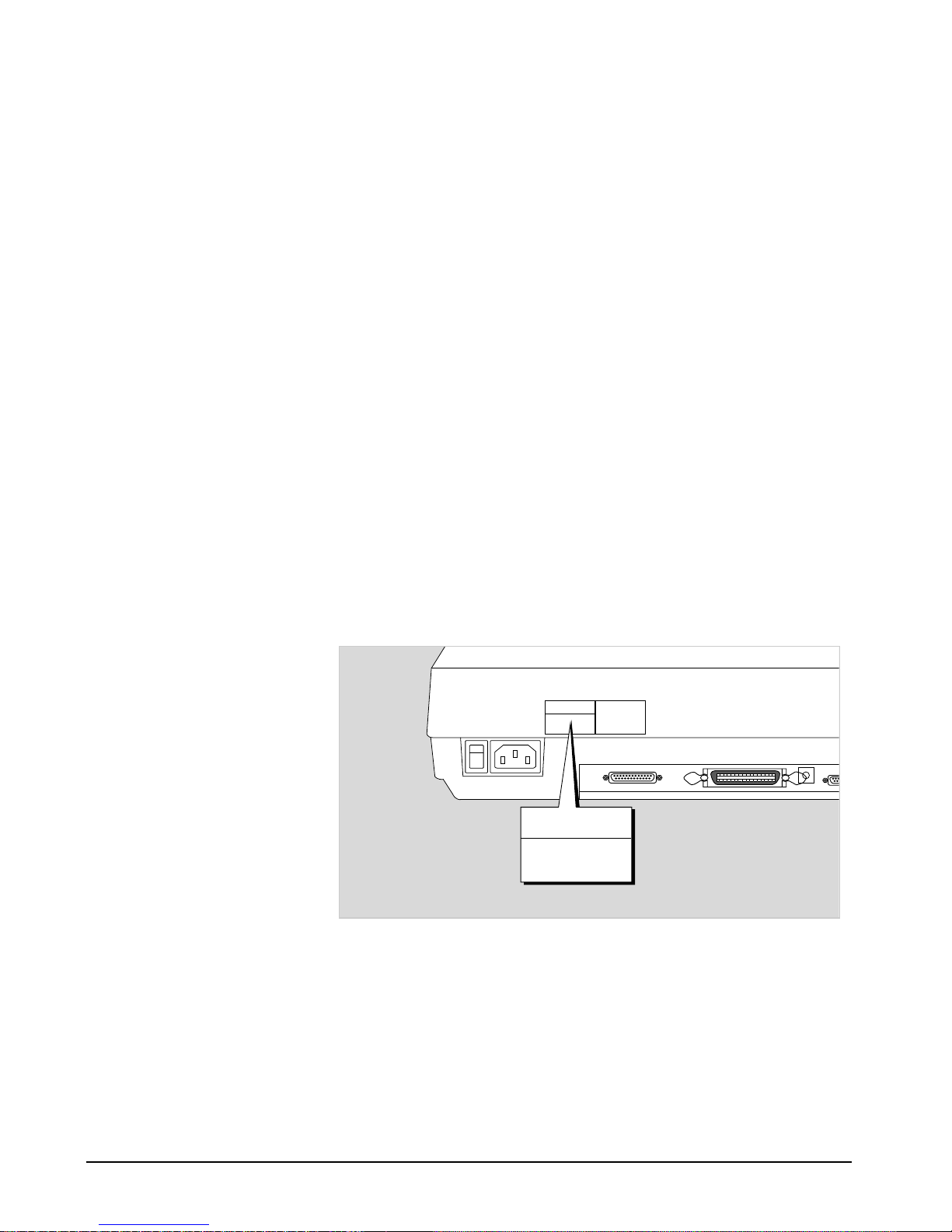
Voltage The voltage of the scanner is indicated at the back of the scan-
ner near the power switch.
Voltage is preset depending on your area, ranging from 100V
to 120V (U.S. and Canada), or 100V to 240V (Europe and
other parts).
In the unlikely event that you receive a scanner with a voltage
setting different from the voltage level used in your area, call
Polaroid Technical Assistance (see page 1-3) for information
about how to return the scanner. Scanners marked with 100V
to 120V will not operate with 220-volt power in Europe or
South America.
Hardware installation 1-5
POLAROID
MODEL NO.: MRS-1200ZS
AC 100-120V–
47-63HZ
1A MAX.
POLAROID
MODEL NO.: MRS-1200ZS
AC 100-120V–
47-63HZ
1A MAX.
Page 9
Installation
• Release the scanner carriage
• Connect your scanner and computer
• Check the SCSI ID
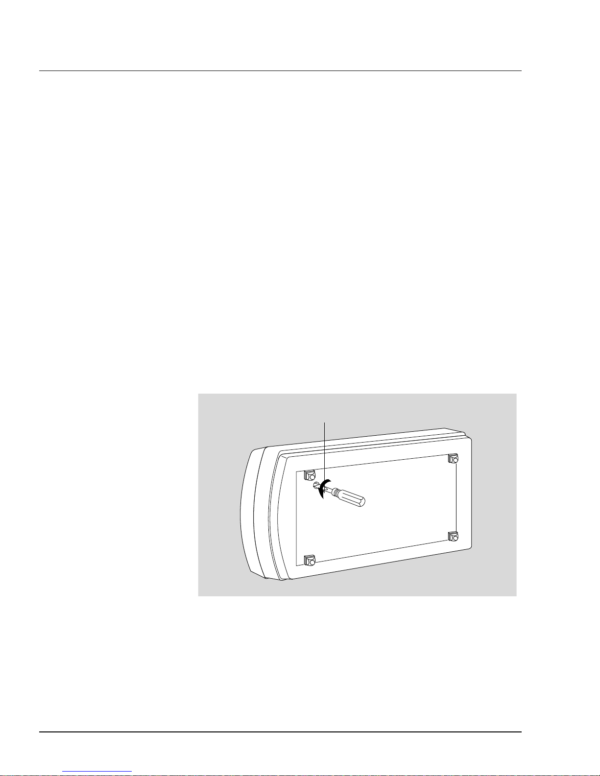
Releasing the carriage Your scanner has a locking screw at the bottom to protect the
scanner carriage mechanism during shipping. Before you can
operate the scanner, you need to disengage the locking screw.
To unlock the scanner:
1 With the scanner turned off, turn the scanner on its side to see
the locking screw at the bottom.
2 Using a screwdriver, turn the locking screw counterclockwise
to unlock it. When unlocked successfully, the screw will push
out a little, becoming nearly even with the bottom of the
scanner.
You can check the lock’s status by pushing on the screw cap.
If the screw springs back, the scanner is ready for scanning.
Cabling The following scenarios are provided to show how to connect
your scanner to the computer and the other components you
may have in your system.
1-6
turn screw
counterclockwise
Page 10
Note:
Polaroid scanners are not internally terminated. Always
use short cables 2-3 feet long for connection; longer cables
can cause SCSI-related problems.
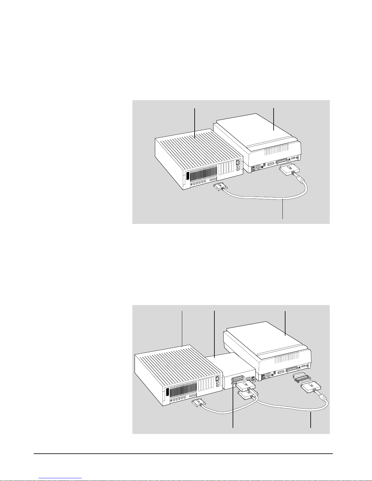
Case 1
Connecting the scanner to a Macintosh. There are no other
SCSI peripherals.
Case 2
Connecting the scanner to a non-Polaroid SCSI peripheral
(like a CD-ROM drive, tape drive, optical disk drive). The
non-Polaroid SCSI peripheral has two 50-pin Centronics
ports. In this case, you will need a SCSI peripheral cable
(see Note on the next page).
Hardware installation 1-7
ScannerMacintosh
SCSI cable
ScannerMacintosh
SCSI cableCentronics port
SCSI peripheral
Page 11
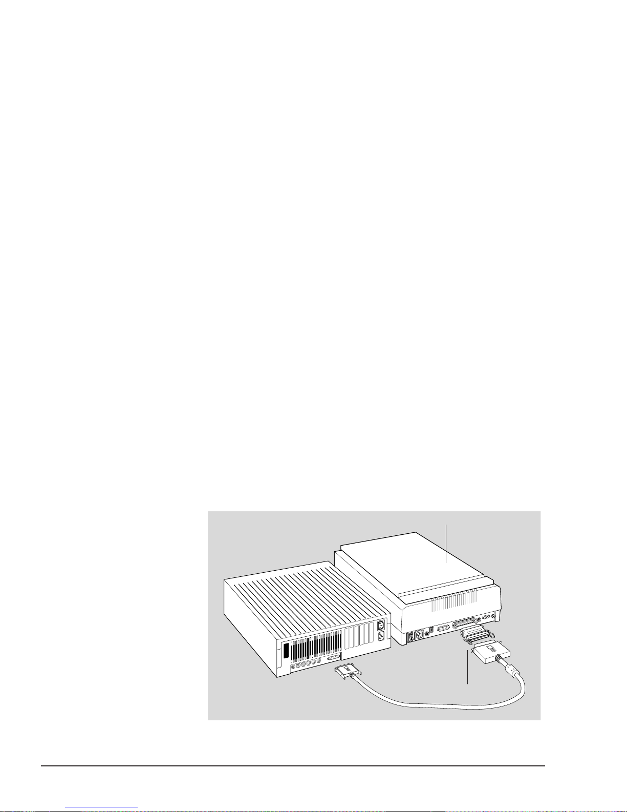
Case 3
Similar to case 2, but the non-Polaroid SCSI peripheral has a
50-pin port and a 25-pin port. In this case, you can use the
cable provided with the scanner, but you will need a terminator.
Note:
SCSI peripheral cables and terminators are not included
with your Polaroid scanner but can be obtained from any computer reseller. For your SCSI peripheral cable, use cables no
longer than 4 feet; longer cables may cause SCSI-related problems. The use of terminators is explained more fully in the next
section,
Using terminators.
Using terminators Depending on your system, you may need to use a cable termi-
nator on your installation. A terminator is a piece of electrical
equipment installed at the end of a SCSI chain linking your
computer with a SCSI device. The terminator ensures that the
electrical impulses going through the path are properly routed
and absorbed.
When to use a terminator
Polaroid scanners are not internally terminated, and Polaroid
does not provide a terminator in its scanner package. You may
or may not need a terminator, but because of varying SCSI standards, there is no way to predict with absolute certainty
whether or not you need one.
If you get odd symptoms after hooking up your Macintosh and
scanner, or if your Mac refuses to boot up properly after you
installed the scanner, this may indicate that you need a termina-
1-8
scanner
terminator
Page 12

tor (or a shorter cable). In this case, obtain a terminator from
a computer reseller, and use it as part of your installation.
On the other hand, if you are hooking up your Macintosh to
a daisy chain with two or more SCSI devices (such as a scanner and a CD-ROM drive), you will definitely need a terminator, and the terminator should then be on the last SCSI device
on your daisy chain. There should never be more than two
terminators on your system (one is usually inside the hard
disk of your computer, and one should be outside on the last
SCSI device).
To install a terminator if you’re hooking up a Macintosh, a
scanner, and a SCSI peripheral, refer to the diagram in Case 2
on page 1-7.
The SCSI ID A SCSI ID is a number assigned to each SCSI device in your
daisy chain to differentiate the devices from one another.
The SCSI ID for Polaroid scanners is set at default to 6. You
won’t need to change the SCSI ID on your scanner unless
another SCSI device on your system (such as a tape drive or
CD-ROM drive) is using the same number.
To set the SCSI ID number:
1 Locate the SCSI ID selector, which is on the back panel.
2 To change the SCSI ID, press the push-button selector. See
Notes on SCSI numbers for numbers that can be used.
Hardware installation 1-9
6
+
_
SCSI ID selector
Page 13

Notes on SCSI ID numbers
• Each SCSI device must have a unique SCSI ID number.
• Valid SCSI ID numbers are 0 to 6. Do not use SCSI ID #7,
which is used to carry a self-test for the scanner and make the
carriage move back and forth. SCSI ID #8 and #9 are also not
used.
• The Macintosh internal hard disk usually occupies SCSI ID
#0 or #1, but it can be set to any number.
SCSI conflicts
Conflicts between your scanner and other SCSI hardware
devices in your system can happen, owing to the varying SCSI
standards that are used for SCSI peripherals today.
If you are having SCSI conflicts:
• Change the order of your SCSI devices in the daisy chain.
Because of the varying SCSI standards in use for SCSI peripherals, some SCSI conflicts may be resolved by moving the
scanner and other SCSI peripherals to different positions in
the chain.
• Check the SCSI ID number of your SCSI devices. Make sure
that no two devices have the same ID. The SCSI check feature
in the CS-600 PtP scanning software can tell you what the IDs
are of the devices in your SCSI chain.
• Use a shorter cable (4 feet or shorter) for each segment of the
chain. The use of longer-than-authorized cables accounts for
more than 50% of SCSI-related problems.
• Make sure that none of the middle SCSI devices are terminat-
ed, and make sure that only the last SCSI device is terminated.
• Always terminate the last device in your SCSI chain with an
external terminator and not an internal terminator.
1-10
Page 14

Operating the scanner
• Performing the power-on self-test
• Positioning a document
• Scanning thick documents
• Notes on using the TMA and ADF scanner accessories
Performing the The power-on test is a quick self-checking mechanism that the
power-on test scanner carries out after you turn it on.
This is what happens after the scanner is turned on:
1 POWER indicator on the front panel of the scanner lights up.
2 READY indicator beside the POWER indicator flashes briefly.
After a 30-second warm-up period, the scanner carries out a
self-test, with the scanner carriage moving back and forth
about a half-inch. If no problems are detected, the READY
indicator stays lit.
Note:
If there are problems with the POWER and READY
indicators, see the Troubleshooting section in the Appendix.
3 The fluorescent lamp inside the scanner should be on too by
this time. The lamp should never go off while the scanner is
on.
Note:
If the scanner lamp doesn’t come on, starts to flicker,
or gets dim, see the section Replacing the scanner lamp at the
end of this chapter.
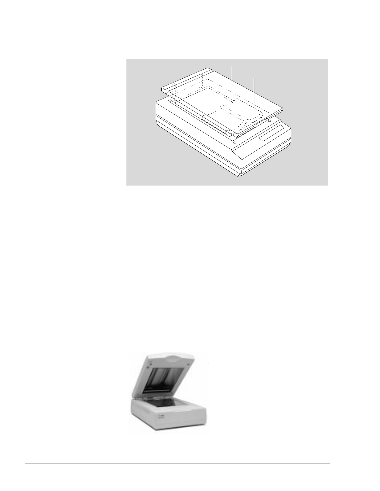
Positioning 1 Lift the scanner cover.
a document
2
Place the document face down on the scanner glass. The top
left corner of the document (when the document is held
upright for normal reading) should be at the "0,0" position
on the ruler guides running alongside the scanner glass.
Hardware installation 1-11
Page 15
Scanning thick 1 Lift the scanner cover high enough so that there is
documents enough room to place the document on the scanner glass.
2 Lower the scanner cover. You are now ready to start scanning.
Using scanner Your scanner is a powerful imaging device, but there are
accessories scanner accessories available that can enhance your scanning
efficiency.
• The Transparent Media Adapter (TMA) doubles the power of
your scanner as it allows you to scan transparencies. TMAs
have their own source of lighting, which is crucial to scanning
transparencies as it prevents images from being exposed to too
much lighting and getting washed out as a result.
Although 35-mm slides and filmstrips are not recommended
due to their small size and lack of resolution, you can use the
TMA to scan slides ranging from 35-mm slides and filmstrips
to transparencies as large as 8"x10".
1-12
lift scanner cover
lay thick document
on the scanner
Transparent Media Adapter
attached to the scanner
Page 16

Miscellaneous
• Returning your scanner
• Locking the carriage
• Replacing the scanner lamp
• Returning your scanner
Your Polaroid scanner has been built to exacting standards.
Just like any piece of electrical equipment, however, your
scanner or the delicate parts in it are subject to wear and tear,
and may malfunction for any number of reasons. If your scanner needs to be serviced or repaired, do the following:
For U.S. users:
• Call Polaroid Technical Assistance (see page 1-3) to get a
Repair Merchandise Authorization (RMA) number.
• Lock the carriage (discussed in the next section)
• Pack the scanner in the original box without any software,
and send the interface cables if applicable. If you have lost the
original box, you will need to buy one from Polaroid for a
nominal fee.
• Send the scanner to Polaroid
Important:
Make sure the RMA number is on the address
label and is visible. Packages without an RMA number or
with the wrong RMA number on the outside of the box will
be refused and returned to sender.
For Canadian users:
Call Polaroid Technical Assistance (see page 1-3). You will be
given an RMA number and address to where your scanner
can be sent for repair.
For users in parts other than the U.S. or Canada:
Call your authorized dealer for further instructions.
Hardware installation 1-13
Page 17
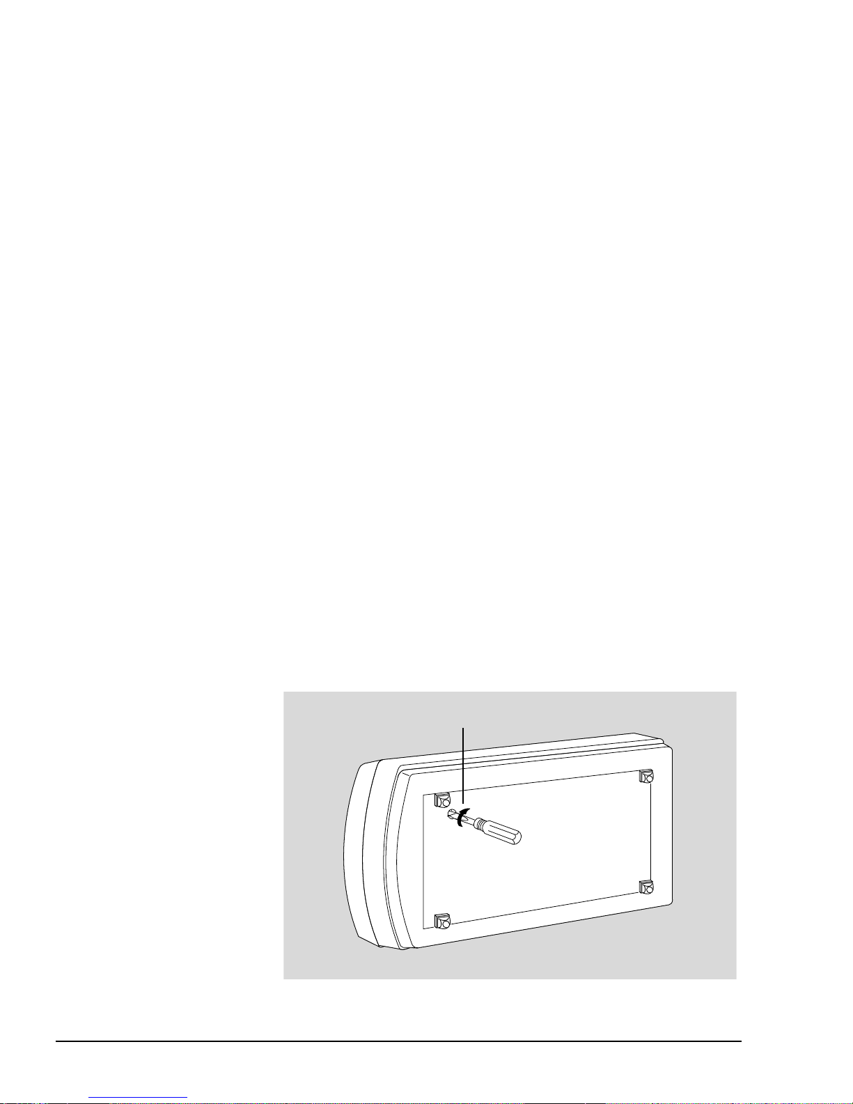
Locking the carriage You need to lock the scanner carriage if you wish to ship back
your scanner for any reason. The carriage must be locked to
prevent the mechanism from moving during shipping and getting damaged in the process.
In addition, you need to pack the scanner in the original box
in which it came. No scanner will be accepted in a packaging
other than the authorized Polaroid packing box. If your box is
lost, call Polaroid Technical Assistance (see page 1-3) to purchase a new one.
Important:
Polaroid will not be liable for scanners that are
damaged during transit because the carriage had not been
locked or was not packed in the original or authorized packaging.
Locking the scanner:
1 Turn the scanner off and then back on. The carriage will
move forward a bit and then return to its standby position.
When the carriage stops moving, turn off the scanner. Be sure
that the carriage is in the standby position before you tighten
the locking screw. Otherwise, the carriage won’t be locked
properly and can get damaged during shipping.
2 Turn the scanner on its side and locate the locking screw at
the bottom of the scanner. To lock, turn the locking screw
clockwise one-fourth turn while pushing it in simultaneously.
The screw should stay in and not pop back out.
1-14
turn screw
clockwise
Page 18

Replacing the If the lamp inside your scanner does not come on or if it
scanner lamp begins to flicker or dim after some time, the lamp may need to
be replaced.
If this is the case, call Polaroid Technical Assistance (see
page 1-3).
Hardware installation 1-15
Page 19

2 Software installation
Overview
This section covers the installation of the CS-600 Software
scanning software and related software included with your
scanner package.
Depending on your scanner model, application software bundled with your scanner may include Adobe Photoshop, or
Caere OmniPage Direct.
In addition, a utility called Microscan is included with all
scanners for added value. Microscan is a compact application
that allows users to scan in an image without having to open
a large application. Microscan installation procedures are provided in this section.
2-1
Page 20

Installing the CS-600 Software and related software
This section provides information on installing the CS-600
Software Plug-in scanning software, along with related application software.
• If you have Adobe Photoshop included with your scanner and
you plan to use the software, follow the instructions in this
section.
• If you don’t have the above application software with your
scanner, you can use instead the Microscan utility included
with all our scanners.
page 2-5 for Microscan installation procedures.
Step 1
Install the image-editing software (Photoshop). To do this,
insert the first software disk (the disk labeled #1 in the series)
into your computer, and run the installer program. Follow the
screen instructions to install the software, and refer to the
documentation that comes with the software for additional
instructions if needed.
Skip this section and instead see
Step 2
Install the CS-600 scanning software.
1 If you have a Power Mac or Performa Power Mac computer:
Install only the disk labeled as “CS-600 Software for Power
PC”. Do NOT install the other two disks.
2 If you have a non-Power Mac computer:
a Start your computer with the Shift key held down to turn
Extensions off and wait until you see the sign “Welcome
to Macintosh”. See the next section for more details on
installing CS-600 Software.
b Install the Apple Shared Library Manager (ASLM) disk
provided with your scanner package. Note: You must
have system 7.0 or higher on your Macintosh to install
ASLM.
c Install the CS-600 Software for non-Power PC disk. See
the next section for more details.
2-2
Page 21
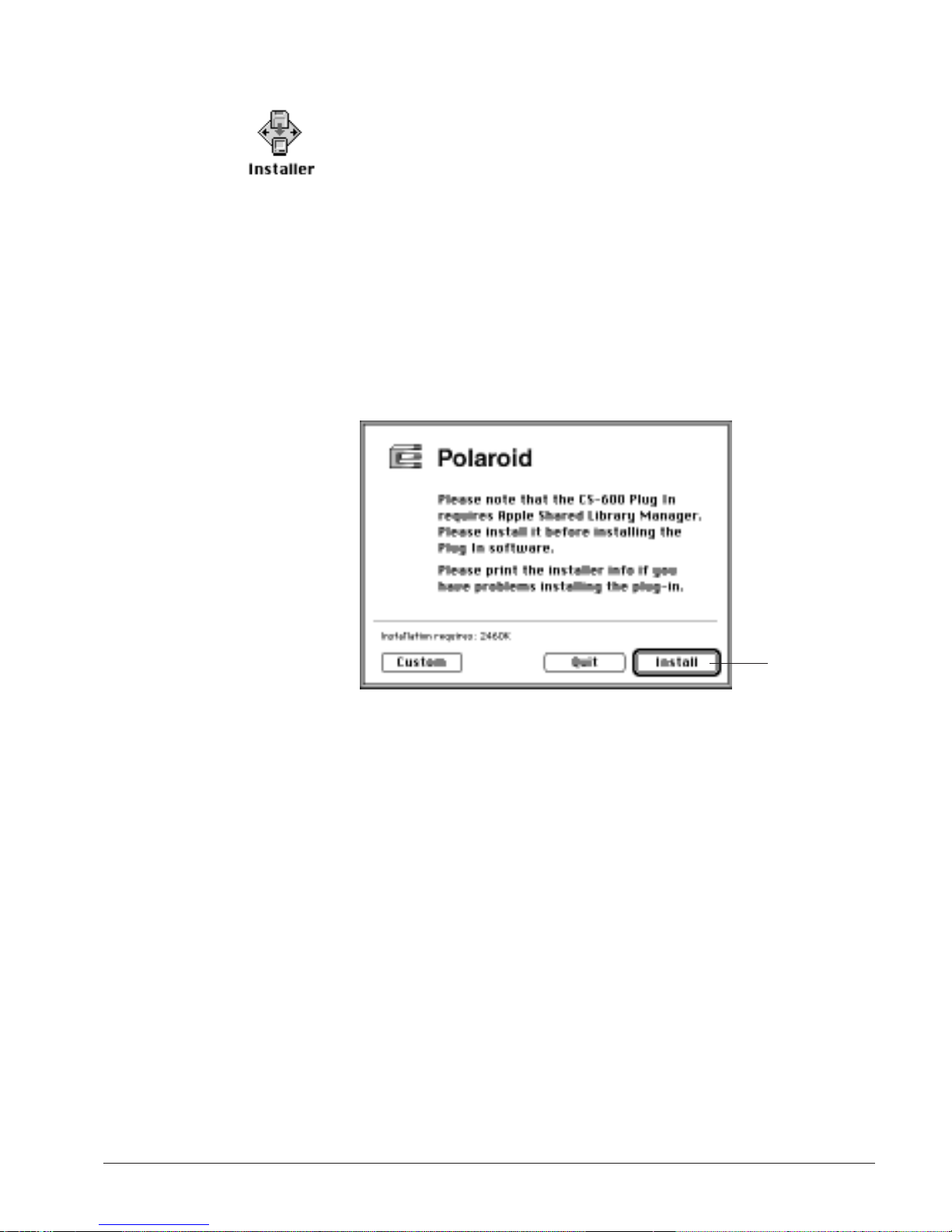
Installing CS-600 1 Insert the CS-600 Software disk into your computer.
Software
Double-click on the disk to open it, then double-click on the
2
Installer icon to start installation.
3 When the CS-600 Software logo appears, click on Continue.
In the next window, you will be able to see the latest information and changes to CS-600 Software. Save this text and read
it since it may contain valuable information regarding installation and troubleshooting that is not included in this manual.
Then, press
Continue to move on.
4 Next, you will be asked if you wish to do a custom install or a
full install. Click on Install for full installation.
Click here to
start full
installation.
Software installation 2-3
Page 22
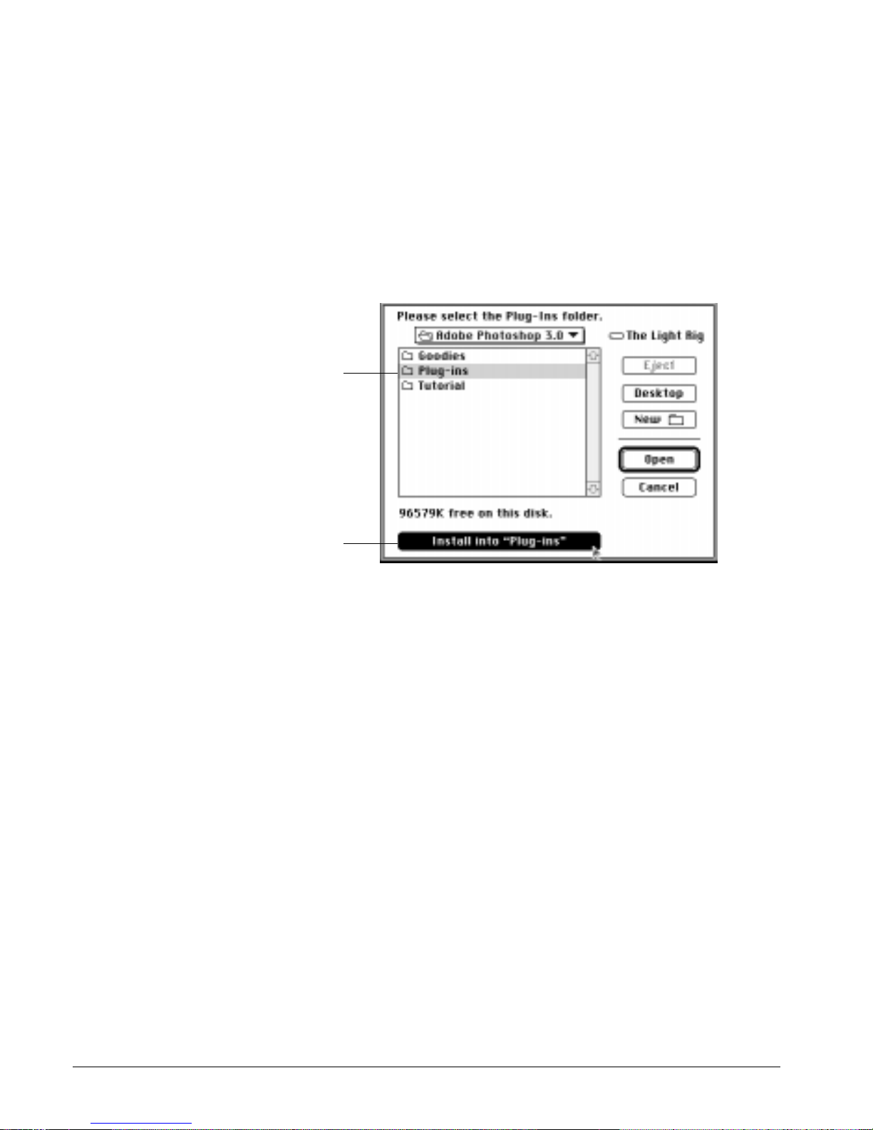
5 The next screen asks you to select your Plug-ins folder.
a If you have Photoshop:
• Select the hard disk by double-clicking on it.
• Select the Photoshop folder by double-clicking on it.
• Highlight the Plug-ins folder by clicking on it only once.
There will be a button on the bottom of this dialog box
which now says Install into plug-ins. Click on this button.
The files will be copied for you automatically.
a
b
a Go to this location (the Plug-ins folder under Photoshop).
b Click on this button below the dialog box.
6 After all necessary files are copied, a screen will appear
informing you that installation is successful and complete.
Click on the Quit button to exit the install program..
2-4
Page 23

Installing the Microscan utility
Microscan is a compact application that allows users to scan in
an image without having to open a large application. By running Microscan, you can call up a plug-in module of your
choice and start scanning. The images are not displayed but can
be immediately saved in a graphic file format of your choice
(EPS, PICT, or TIFF).
Microscan is not intended as a substitute for your image-editing
software but is aimed at users who don’t have applications like
Photoshop and yet still need a program where images can be
saved and exported later to applications. Microscan is helpful
for those wishing to scan a large number of images at one time
without having to view the images. Since the images are not displayed after they’re scanned but are saved as image files, considerable time can be saved by using this handy utility.
To install Microscan:
Step 1
Install the Apple Shared Library Manager (ASLM), which is
provided with your scanner package. You must have system 7.0
or higher on your Macintosh to do this, and the ASLM must be
installed or your scanning software will not work.
1 Restart your computer with the Shift key held down. Keep the
key down until you see the message “Welcome to Macintosh.”
2 Insert the disk marked Apple Shared Library Manager into your
computer.
3 Double-click on the disk to open it, then double-click on the
Installer icon to start installation.
Step 2
Install the Microscan utility.
1 Insert the CS-600 Software disk into the drive. The disk is
labeled CS-600 scanner controller for the Macintosh.
2 Double-click on the disk to open it, then double-click on the
Installer icon to start installation.
Software installation 2-5
Page 24
3 When the CS-600 Software logo appears, click on Continue.
In the next window, you will be able to see the latest information and changes to CS-600 Software. Save this text and read
it since it may contain valuable information regarding installation and troubleshooting that is not included in this manual.
Then, press Continue to move on.
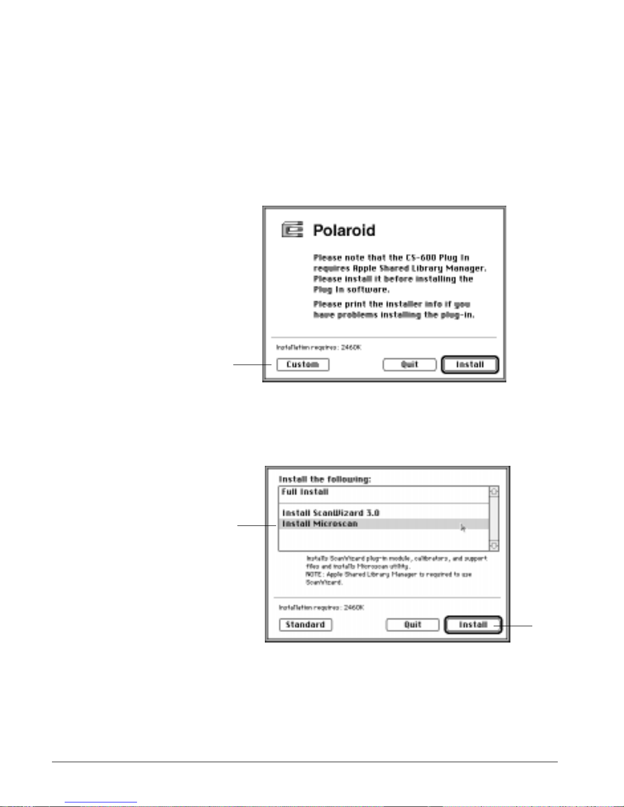
4 Next, you will be asked if you wish to do a custom install or a
full install. Click on Custom for a custom installation.
Click
here
5 Another window will appear asking you to select the module
to be installed. Select Microscan by highlighting it, and click
on Install.
a
b
a Select MicroScan.
b Click on this button to start installation.
2-6
Page 25

6 Next, you will be asked which hard disk the software will be
installed in. Select the disk, and click on Install. Microscan
files will start to be copied.
7 After files are copied, click on Quit. Microscan is now
installed in a folder on your hard disk called the Microscan
folder.
Step 3
Install CS-600 Software.
1 Insert the CS-600 Software disk into your computer. Double-
click on the disk to open it, then double-click on the Installer
icon to start installation.
2 When the CS-600 Software logo appears, click on Continue.
Next, you will be asked if you wish to do a custom install or a
full install. Click on Install for full installation.
3 The next screen asks you to select your Plug-ins folder.
• Select the hard disk by double-clicking on it.
• Select the Microscan folder by clicking on it only once. There
will be a button on the bottom of this dialog box which now
says Install into Microscan folder. Click on this button. The
files will be copied for you automatically.
4 After files are copied, click on Quit.
Software installation 2-7
Page 26

Installing OmniPage Direct
1 Insert the OmniPage Direct software disk into your comput-
er. Double-click on the disk to open it, then double-click on
the Installer icon and follow the screen instructions to install
the program.
2 At some point during the installation, you will be asked to
choose your scanner driver.
• If you’re using the CS-600 , select CS-600 Driver.
Note:
the instructions are provided here in case you obtained your
copy of OmniPage Direct from retail channels.
3 When installation finishes, go to the Apple menu and select
the Chooser.
• If you are using the CS-600 , select CS-600.
4 To scan, open your word-processing program. Choose New
from the File menu, then go to the Apple menu and choose
OmniPage Direct. Then choose your page options, and click
on the Scan button to start scanning. For more details on
scanning text, see the chapter Sample Scanning.
Note:
OmniPage Direct and deselect Auto Intensity. Then click on
the OK button.
OmniPage Direct is not bundled with the CS-600 , but
To increase scanning speeds, click on More Options in
Installing Polaroid Print to Press
1 Insert the Polaroid Print to Press software disk into your
2 Double click on the Print to Press Installer.
3 Follow the on-screen instructions.
2-8
computer.
Page 27

3 Reference
Overview
The CS-600 PtP scanning software is the program that acts as
a bridge between your scanner and a target application, such
as Adobe Photoshop or MicroFrontier Color It.
In practical terms, this means you use the CS-600 to capture
images placed on your scanner, edit those images, then place
them in your target application. And with its many editing
tools and features, the CS-600 can save you considerable time
from having to do touch-ups in your image-editing software.
3-1
Page 28

This section is a listing of features found in the CS-600 PtP
scanning software.
The reference information is organized in four parts, following the structure of the software which shows the four major
windows. The subjects covered in this section include the following:
• The CS-600 Software Plug-in
• Preview Window
• Settings Window
• Information Window
• Scan Job Window
Here are some of the things you can do with the
CS-600 PtP:
• Select the type of image to be processed and scanned. You can
put one type of image on the scanner and scan that in its original form, or you can scan it in another form altogether. For
example, you can have a color photo and scan it in the same
color mode, or you can scan it in a different image type such
as grayscale or line art.
• While in preview mode, the image can be adjusted through
the image-enhancement tools in the Settings window. These
tools allow you to adjust image features such as brightness,
contrast, and exposure; shadows and highlights; gamma or
midtones (mid-gray levels); hue or saturation; and apply various filters for special effects.
• Clicking on an image-enhancement tool calls up the Advanced
Image Enhancer (AIE) dialog box. While in the AIE dialog
box, you can see thumbnail displays of the image, make
changes and see the effects applied in real time (see “before”
and “after” versions instantly). You can also switch to another tool without leaving the AIE dialog box, as well as switch
among scan jobs if you have multiple scan jobs. The imageenhancement functions are among the most powerful features
of the CS-600.
3-2
Page 29

• Perform a preview or preliminary scan. This is done with the
Preview button in the Preview window, and it allows you to
see a preliminary view of the image before it’s actually
scanned. Previewing an image allows you to do further
enhancements if necessary, and it also lets you select the final
area to be scanned in case you wish to crop the image. When
the image is ready to be scanned, clicking on the Scan button
will activate the scanning process, and the image will then be
delivered to your target application.
• When changes are made to the image, the changes can be easi-
ly verified through the Information window, which displays
changes to RGB values. This information can be helpful for
those working with color values.
• Create multiple scan jobs. A scan job is simply a task that you
designate the scanner to process and scan. For example, one
scan job may be in grayscale and another may be in color.
The two scan jobs can then be manipulated and scanned separately, and you can switch between scan jobs easily while
making changes. The CS-600 Software Plug-in’s ability to
process various scan jobs concurrently adds tremendous flexibility to scanning.
Reference 3-3
Page 30
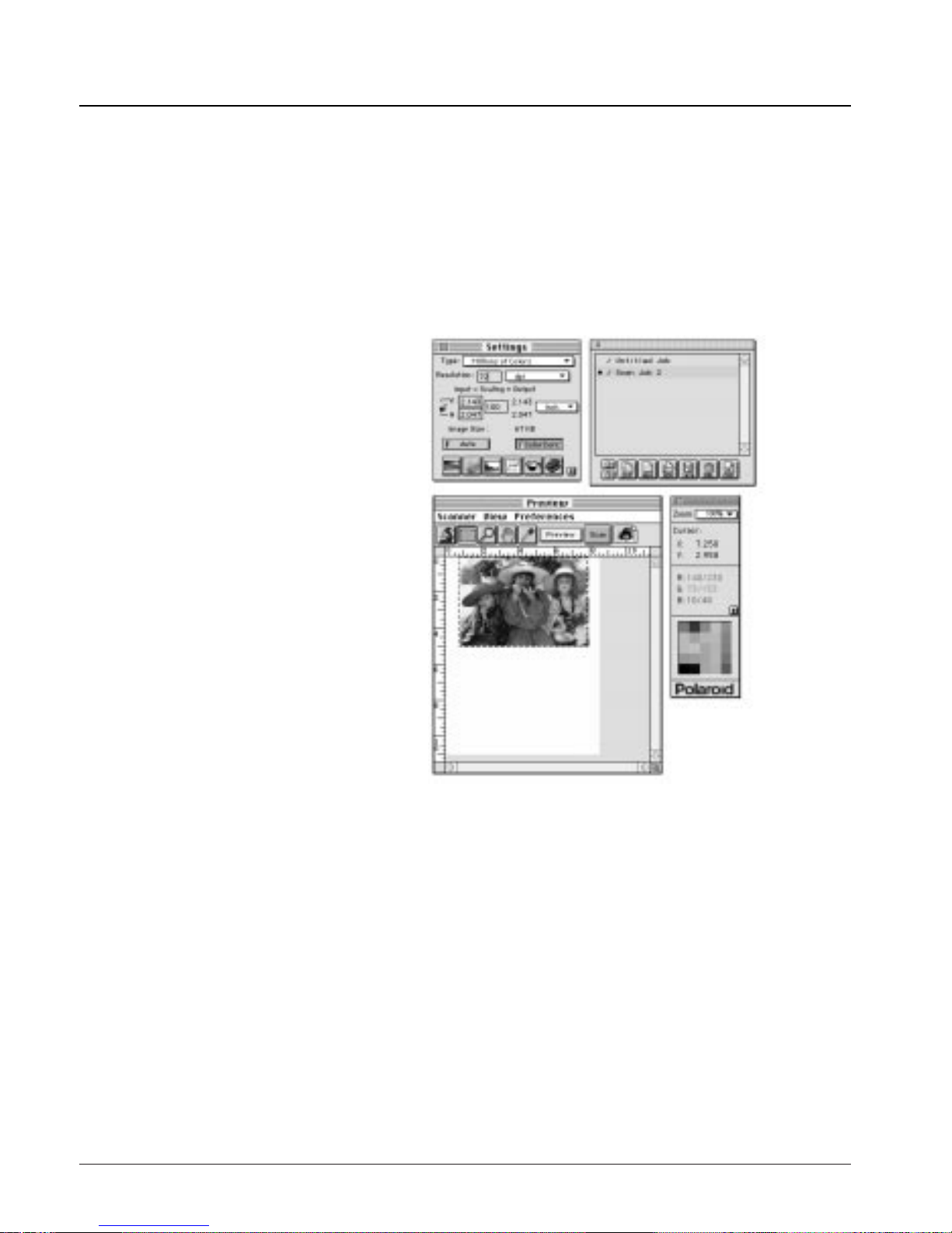
The CS-600 PtP
The CS-600 PtP consists of four major windows: Preview,
Settings, Information, and Scan Job.
The Preview and Settings windows appear automatically after
the CS-600 is started up. The Scan Job and Information windows, however, are hidden, and to see them, go to the View
menu in the Preview window and click on the commands
Show Scan Job window and Show Info window.
a b
d
c
a Settings window contains scanning parameters for outputting
the image and includes image-enhancement tools.
b Scan job window provides key functions in processing scans.
c Preview window has commands and tools for controlling the
scanner.
d Information window provides information on the preview
image.
3-4
Page 31

To bring up the CS-600:
Start up your image-editing software. When the application
opens, choose Acquire from the File menu, and choose
CS-600 from the submenu.
On the very first time that the CS-600 is started up, only the
Preview and Settings windows will appear. To see the Scan
Job and Information windows, go to the View menu and
choose the Show command for both windows.
The next time you start up the CS-600, the screen will look
exactly like the last time you exited the software. This means
that if you had all four windows open the last time you quit
the CS-600, the same four windows will appear the next time
you start it up.
Reference 3-5
Page 32

Preview window
The Preview window is the most prominent window of the
four major windows, and it includes the various commands
and tools for controlling the scanner.
f
a
b
c
e
d
a The Menu Bar includes the different menus for setting up the
scanner (Scanner menu), controlling view options (View
menu), customizing the software (Preferences menu).
b The Tool buttons simplify the performance of certain tasks.
The Tool buttons are (left to right):
• Zoom Preview
• Scan Frame
• Magnifying Lens
• Hand
• Color Picker
c The Rulers are located on both sides of the window to help
you with measurement and alignment.
d The Preview Area is where the preview image appears after
you click on the Preview button.
3-6
Page 33

The Menu Bar
e The Scan Material Status icon shows your scan material:
whether it’s reflective, positive or negative.
f The Action buttons generate a specific action from the scan-
ning software. The Action buttons include Preview and Scan.
Reference 3-7
Page 34

Scanner menu
The Scanner menu lets you:
• Show your scanner model or select a scanner if you have mul-
tiple scanners
• Get information about your scanner
• Get information about the SCSI chain
• Exit the CS-600
Scanner Model The top of the scanner menu displays the scanner model
you’re using and its SCSI ID. If you have multiple scanners on
your system, all the scanners are shown with their respective
SCSI IDs, and the current scanner is indicated by a check.
Only one scanner can be accessed at a time. To switch among
various scanners, select the scanner to be used.
Get Current Scanner Info This command provides information about your current scan-
ner. When you choose this command, a dialog box appears
showing the scanner model, SCSI ID number, firmware version, and driver information.
Get SCSI Chain Info This command allows you to see the SCSI devices on your
SCSI chain and the SCSI ID number of the devices.
3-8
By default, all numbers are selected by the check boxes. To
Page 35

allow the CS-600 to start up more quickly, select only the
boxes that match the SCSI ID of your scanner (or scanners, if
you have multiple scanners on your system). This will make
the CS-600 bypass the numbers for your other devices and
focus effort on simply detecting scanners. If you’re not sure
about which numbers to specify, check all the boxes.
c
a
b
a Click on the Probe button to update information or mount a
SCSI device if it’s not showing in the dialog box.
b By default, all numbers are crossed out to enable quick start-
up the next time. #7 is not provided as an option because it’s
reserved for the CPU.
c SCSI devices are shown with their corresponding SCSI ID
numbers.
To use the SCSI Check feature:
1 Choose the Get SCSI Chain Info command. The SCSI Check
dialog box will appear.
2 If your scanner does not show, click on the Probe button.
Make sure your scanner is connected and turned on.
Quit This command allows you to exit the CS-600 without scan-
3 Check the numbered box corresponding to the SCSI ID of
your scanner or scanners. Click OK to close the dialog box.
ning. You can also quit at any time by pressing Command + Q
(the Apple Command and Q keys) simultaneously.
Reference 3-9
Page 36

View menu
The View menu lets you:
• Get a full page preview or zoomed-in (enlarged) view of an
image
• Resize the preview window
• Show or hide the Settings, Information, and Scan Job windows
• Obtain information on the CS-600
Full Page Preview This command shows one of the two viewing modes available
(the other being the zoomed preview, explained in the next section).
The full page preview is a preview of your image as defined by
the parameters set in the Preview Setup command (in the
Preferences menu). For instance, if your image is 8"x 5" but
the dimensions in the Preview Setup are 4"x 3", your full page
preview will be 4"x 3".
The maximum size of the full page preview varies, depending on
your scanner model. For example, if the scan bed (the glass surface) of your scanner has a maximum size of 8.5" x 11", the
maximum full page preview will be limited to those dimensions.
The size of the full page preview can be changed by setting new
dimensions in the Preview Setup command. The new dimensions will take effect, however, only with the next preview.
This means you need to click on the Preview button so that the
scanner does a new preview; only then will you see the new
dimensions of the full page preview.
3-10
Page 37

You may wish to change the size of your full page preview to
improve performance and save memory. A smaller preview
area will occupy less memory, speed up processing, and yield
a higher-resolution preview. This is because the CS-600 takes
your preview image and dynamically calculates how best to
display that image in the smaller preview area — resulting in a
higher-resolution view.
a
Full Page preview (8.5"x 11") as
determined by dimensions in
the Preview Setup.
b
Full Page preview changes to
6"x 9" because dimensions in
Preview Setup were changed.
a Preview area matches dimensions in Preview Setup command.
b Preview changes as dimensions change. Note new ruler mea-
surements.
Reference 3-11
Page 38

To use full page preview:
1 Full page preview is the default view. It will be dimmed if the
current view is already the full page preview. It is available for
use only if you are in zoomed preview mode.
2 To change the size of the full page preview, click on the
Preview Setup command in the Preferences menu. When the
Preview Setup dialog box appears, specify the new dimensions
for the full page preview. (See the Preview Setup command for
more details.)
3 To make the new preview dimensions take effect, do a new
preview by clicking on the Preview button, and in a few
moments, the new preview area will appear.
Zoomed Preview This command displays the magnified view that results from
using the Zoom Preview tool.
The zoomed preview is the view of a specific part of the image
shown in higher resolution with more visible detail. If you
have zoomed preview enabled, the view is stored in memory,
and you can easily switch between full page preview and
zoomed preview.
The zoomed preview is different from the zoomed-in view
obtained from the Magnifying Lens tool. The zoomed-in view
is simply an enlarged view, but it is not in high resolution.
Full Page preview Zoomed preview
3-12
Page 39

To use zoomed preview:
1 Click on the zoom preview tool (leftmost tool in the Toolbar
that looks like a microscope).
2 Move the pointer to the preview image and draw a scan frame
around the area to be zoomed in, then click inside the scan
frame. The selected area will be magnified to give you the
zoomed preview. For more details, refer to the section on the
Zoom Preview tool.
After you use the zoom preview tool to create the zoomed
preview, the Zoomed Preview option in the View menu will
be enabled. You can then switch between Full Page Preview
and Zoomed Preview as your viewing modes.
Resize Window to Fit This command adjusts the preview window to fit the preview
area.
In the example below, the preview window is larger than the
preview area, as the gray space (which denotes the preview
window) exceeds the white area (which denotes the preview
area). The preview window can also exceed the preview area
if, for instance, you manually enlarged the preview window
(by dragging on the resize box). If you find that the gray area
is far too big and wish to utilize window space more efficiently, use this command to resize the preview window.
a b
Window before resize Window after resize
a Preview window (total area including gray space) is bigger
than preview area (area of white space only.
b Window resized. Note lower half of window has disappeared
(gray area gone) to fit the preview area. Gray area on right
side of window is still left because window width is already at
its minimum.
Reference 3-13
Page 40

To use this feature:
Choose the command Resize window to fit in the View menu.
You can also do this by pressing Command + R (the Apple
Command and R keys) simultaneously.
This command is available only if the current zoom level is
100%, and is disabled if zoom is set to other levels. To verify
the zoom level, open the Information window and look up the
zoom level.
Show / Hide commands These commands allow you to switch between showing or
hiding the Settings, Scan Job and Information windows on
your screen.
To use this feature:
The Show / Hide commands are toggle commands, which
means they can be used to show or hide a window, as the case
may be.
Tip:
Another way to close or hide an active window is to click
in the close box on the left corner of the active window.
This is the same as using the Hide command.
About This command gives you information on the CS-600 PtP scan-
ning software.
3-14
Page 41

Preferences menu
The Preferences menu lets you:
• Choose the correct scan material
• Create effects like invert and mirror
• Create cursor lines to help you with alignment
• Control the size of your preview window
• Keep your scan module after you finish scanning
• Create a smoked glass background to help distinguish the
active scan frame
• Set other options, such as specifying a working directory
for files
Scan Material This command allows you to select the correct scan material.
Scan materials can be generally classified into three types:
• Reflectives, such as photographs or prints.
• Positives, such as slides.
• Negatives, such as the negative film you use for your camera.
The default scan material selection depends upon the scanner
you’re using, and the choices available to you in the Scan
Material submenu will also depend on your equipment.
For instance, the positive option appears only if you’re using a
Transparent Media Adapter (TMA) with your scanner. The
negative option appears only if you have DCR installed and
are using the TMA to scan a negative.
Reference 3-15
Page 42

If you are scanning negatives or positives, make sure you specify the correct scan material, or you will get inaccurate scanning results.
Note:
The Scan Material function is also related to the Tints
tool, an image-enhancement function in the Settings window.
Refer to that section for more details.
To use the scan material feature:
Choose the Scan Material command in the Preferences menu.
From the submenu that appears, select your scan material. A
check appears next to the selected option. The option you
select will also be shown in the Scan Material Status icon
(discussed on page 3-17).
Note:
If your Preview window is close to the right edge of
your monitor, the Scan Material submenu may appear on the
left side instead of on the right (as shown above). To resolve
this, move the Preview window towards the left to create
enough room for the submenu to drop down on the right.
3-16
Page 43

The Scan Material Another way to access the Scan Material menu is to use the
Status icon Scan Material Status icon, located to the right of the Scan
Button.
Scan Material
Status icon
The appearance of the Scan Material Status icon changes,
depending on whether your scan material is reflective, positive,
or negative.
The positive and negative icons become active only if you’re
using a Transparent Media Adapter with your flatbed scanner.
• If you’re scanning a reflective (such as a photo or print), the
Scan Material status icon appears in the form shown at left.
When you click on the icon and hold down the mouse, you’ll
see the Reflective option checked.
• If you’re scanning a positive transparency or filmstrip, the Scan
Material Status icon appears in the form shown at left. Notice
the perforations on the top and bottom of the icon (characteristic of slides) to distinguish it from the reflective icon. When you
click on the icon and hold down the mouse, you’ll see the
Positive Transparency option checked.
• If you’re scanning a negative transparency or filmstrip, the
Scan Material status icon appears in the form shown at left.
When you click on the icon and hold down the mouse, you’ll
see the Negative Film option checked.
Reference 3-17
Page 44

Invert This command creates a negative of an image. The Invert
effect is applied to the whole preview image; it cannot be used
for only a specific portion of the image.
When an image is inverted, the brightness value of each pixel
is converted to the inverse value on the 256-step color values
scale. For example, a pixel in a positive image with a value of
255 is changed to 0, and a pixel with a value of 5 is changed
to 250.
Original Invert
To use this feature:
Choose the Invert command in the Preferences menu. A check
appears next to the command when it is enabled.
Horizontal Mirror This command allows you to flip the image so that a mirror
effect is created. The Mirror effect is applied to the whole preview image; it cannot be used for only a specific portion of the
image.
Original Horizontal Mirror
To use this feature:
Choose the Horizontal Mirror command in the Preferences
menu. A check appears next to the command when it is
enabled.
3-18
When the mirror image appears, the scan frame will still be in
the old location, and you will need to move the scan frame if
you wish to define another area.
Page 45

Cursor Auxiliary Lines This command allows you to create horizontal and vertical
grid lines with your cursor to help define a scan frame precisely. Using the grid lines, you can read the measurements off
your ruler more easily.
Cursor auxiliary lines
on the x and y axis
To use this feature:
1 Choose the Cursor Auxiliary Lines command in the
Preferences menu. From the submenu that appears, select how
the cursor lines will appear.
• On both x (horizontal) axis and y (vertical) axis
• On x axis only
• On y axis only
• None (no cursor lines)
Note:
If your Preview window is close to the right edge of
your monitor, the Cursor Auxiliary Lines submenu may
Reference 3-19
Page 46

appear on the left side instead of on the right (as shown
above). To resolve this, move the Preview window towards
the left to create enough room for the submenu to drop down
on the right.
2 Click on the Scan Frame tool.
To see how the cursor lines work, draw a scan frame. Click
on the top left corner of the image as your starting point, then
drag down to form a scan frame.
As you draw the scan frame, cursor lines will appear to help
you draw the scan frame precisely.
When you release the mouse, your scan frame will be aligned
with the cursor lines.
a
b
c
a Click on the Scan Frame tool, then define a starting point.
b Cursor lines appear to the top and left of the image.
c As you drag the mouse down, the scan frame is aligned with
cursor lines on x and y axis (based on your selected option in
the submenu.
3-20
Page 47

Preview Setup This command allows you to set the dimensions of your pre-
view area. When the Preview Setup dialog box (below) comes
up, click on the option you need or specify your parameters.
a
b
c
a Live Preview This option applies only to color scanners. If
Live Preview is enabled, the next option, Color Preview, will
be dimmed.
If Live Preview is on:
• Changes you make to the preview image are shown instantly
(for example, switching from color to grayscale).
• If you’re scanning in grayscale and live preview is on, the
image appears in color unless you specifically change image
type in the Type box (in the Settings window) to a grayscale
mode. This happens because Live Preview always does previews in color.
If Live Preview if off:
• Your preview will be in accordance with your image type
(i.e., if you have a grayscale image, your preview is in
grayscale; with a color image, you get a color preview). If
you apply any image-enhancement control, the changes will
not be apparent until you do a new preview (click on the
Preview button again). Turn off Live Preview if you’re previewing or scanning in grayscale to speed up the process.
Reference 3-21
Page 48

b Color Preview This option applies only to three-pass color
scanners, and is enabled only if Live Preview is not selected. If
this option is turned on, the image will be scanned in whatever scan mode is specified in the Type box (in the Settings window). If it is turned off, the image will be scanned in
grayscale.
c Fast Preview This option allows you to choose your preview
mode.
• If Fast Preview is on: The preview process is faster, but the
quality of preview image is a little coarse.
• If Fast Preview is off: The preview process is slower, but the
quality of the preview image is improved.
The Fast Preview option is a hardware-related feature and
may or may not be available depending on your scanner
model.
The Preview Area The Preview Area option in the Preview Setup dialog box lets
you select the size of your preview area. Choose from the following options: letter, A4, legal, maximum size, or custom
size.
• Maximum refers to the maximum scan area that can be sup-
ported by your particular scanner model.
• Custom will appear if you type in your own specifications
and change any of the edit boxes.
• The Top, Left, Width and Height edit boxes allow you to
specify the dimensions of the preview area. Top and Left refer
to the starting points of the preview area on the x and y coordinates. Width is the expanse of the preview area, and Height
is the depth of the preview area.
• The unit of measurement, indicated on the right side of the
Left box, reflects the unit selected in the Settings window.
3-22
Page 49

Size of preview area if preview Size of preview area if preview
setup is 8.5"x11" setup is 6"x 9"
To set the preview area:
1 Choose the Preview Area size. If you enter any of the edit boxes
marked Top, Left, Width, or Height, the Preview Area size automatically changes to
2 Click OK to accept the settings; click Cancel to abandon.
3 To make the new preview dimensions take effect, do a new pre-
Custom
.
view by clicking on the Preview button. In a few moments, the
new preview area will appear.
Keep Preview Image This command allows you to retain the last preview image you
used; the preview image is kept in the preview window after you
exit the CS-600.
The next time you start up CS-600, this last preview image is
again displayed in the preview window.
Retain Scan Module This command allows you to keep the scan module (the CS-600)
after Scan after scanning has been completed and delivered to your image-
To use this feature:
Choose the Keep Preview Image command in the Preferences
menu. A check mark appears next to the command when it is
enabled.
editing software. This way, you don’t have to go back to the
File-Acquire process to return to the CS-600 scan module.
Reference 3-23
Page 50

This command can be used only in applications (such as
Adobe Photoshop) that allow you to retain the scan module
after a scan is completed. Some applications will not retain
the scan module even if this option is enabled.
To use this feature:
Choose the command Retain Scan Module after Scan in the
Preferences menu. A check appears next to the command
when it is enabled.
Smoked Glass Background This command helps you distinguish the scan frame from the
rest of the material for greater visibility of the scan frame.
With this feature turned on, the part of the image within a
scan frame will stand out, while any material not in a scan
frame is relegated to the smoked glass background. If you
have multiple scan frames, all the scan frames will be visible,
and the current scan frame will be denoted by the marquee
(marching ants).
The Smoked Glass Background, then, helps you focus on just
the part of the image to which you wish to apply controls or
scan.
Moreover, if you have multiple scan frames and each one has
a different setting (one in grayscale, another in color, etc.),
this is also shown clearly if smoked glass is turned on.
c
a
b
a Part of image is in another scan frame, but this is not the cur-
3-24
rent scan frame (no marching ants). Image, however, is still
visible and not hidden behind smoked glass background.
Page 51

b Part of image not in any scan frame and thus hidden by
smoked glass background.
c Current scan frame (with pulsing lines).
To use this feature:
Choose the Smoked Glass Background command in the
Preferences menu. A check appears next to the command
when it is enabled. It is helpful to enable this feature, especially when you are editing a scan frame or applying imageenhancement controls. See the next section for more details.
Note:
Holding down the Shift key while dragging the mouse
allows you to make multiple scan frames.
How Smoked Glass works with image enhancement
When the Smoked Glass feature is enabled, it becomes linked
with the functions of a scan frame and significantly impacts
the way image-enhancement controls and other settings (such
as resolution) are applied. Details follow.
• If you have smoked glass on, a scan frame defined, and set
image-enhancement and other controls (such as changing
brightness, applying a filter, or changing resolution),
enhancements are applied to the scan frame alone
the
.
This means that the part within the scan frame may change in
appearance (as it now has different settings), but because
smoked glass is on, the rest of the image hidden behind the
smoked glass remains unaffected.
With Smoked Glass on,
controls are applied to
the part of this image
within the scan frame.
Reference 3-25
Page 52

• If you have smoked glass off, a scan frame defined, and set
image-enhancement and other controls,
are applied to the entire image
, not just the scan frame
the enhancements
alone.
With Smoked Glass off,
controls are applied to
the entire image.
More This command allows you to specify a working directory
where you can save all temporary and data files, including files
for job templates.
To use this feature:
1 Choose the More command in the Preferences menu. The dia-
log box below appears.
2 Click and hold down the Working Directory box, and from
the pop-up menu that appears, choose your working directory.
3-26
Page 53

3 If you choose Other Directory from the menu, a standard
dialog box will appear where you can specify the working
directory of your choice.
Whatever directory you specify is automatically added to the
pop-up menu above for you to choose from in the future.
If the directory you specify is not found or does not exist, a
warning message appears, and the current directory of the
CS-600 is used instead.
4 When you have completed your choices, click OK to close the
More Preferences dialog box. For the changes to take effect,
exit the CS-600, then relaunch the program.
Reference 3-27
Page 54

The Tool buttons
Zoom Preview tool The Zoom Preview tool gives you the zoomed preview, which
is an enlarged, high-resolution view of an image with more
Usage: To magnify
the view of a preview image in high
resolution, and to
let you switch
between full page
preview and
zoomed preview.
visible detail.
The zoomed preview is different from the zoomed-in view,
which is obtained by using the magnifying lens tool and is not
a high-resolution view. By using the zoom preview tool and
creating the zoomed preview, you can then switch easily
between full page preview and zoomed preview.
a
b
Full page preview Zoomed preview
a Area to be zoomed in with the Zoom Preview tool.
b Selected image part zoomed in (enlarged) in high resolution.
To use the Zoom Preview tool:
1 Click on the Zoom Preview tool.
2 Move the pointer to the preview image and draw a scan frame
around the area to be zoomed in.
3 Click inside the scan frame. The selected area will be magni-
fied to give you the zoomed preview. Only the area inside the
defined scan frame will be zoomed in. To zoom in on a larger
area, go to full page preview and change the size of the scan
frame.
3-28
Page 55

Scan Frame tool The Scan Frame tool lets you create or modify a scan frame,
Usage: To create
a scan frame or
multiple scan
frames in the
preview image.
which is the active area on which controls and commands can
be applied. You can have multiple scan frames, but only one
can be current at a time; the current scan frame is indicated by
a marquee (marching ants). Scan frames can be more easily distinguished if you turn on the Smoked Glass Background command (in the Preferences menu).
a
Image with single scan Image with multiple scan
frame frames
a Current scan frame is denoted by marquee.
b Another scan frame. This is not the current scan frame and can
c
b
be distinguished by the box around the left half of the image.
c Current scan frame.
To use the Scan Frame tool:
1 Click on the Scan Frame tool.
2 Move the pointer (now a crossbar) to the preview image, and
draw a frame enclosing the area to be selected. When you
release the mouse, the scan frame will be in a marquee.
To make multiple scan frames (which would add scan jobs),
hold down the Shift key and drag the mouse. For more information on scan jobs, refer to the Scan Job section of the
Reference.
3 To resize the scan frame, do either of the following:
• Move the cursor to any corner of the frame; the pointer will
change to a double-headed arrow. Hold down the mouse, and
drag to form a new area, then release the mouse; or
• Click on the Scan Frame tool again and restart the area-selec-
tion process.
Reference 3-29
Page 56

Magnifying Lens tool The Magnifying Lens tool enlarges your view of the preview
Usage: To zoom
in or enlarge your
view of the
preview image.
image, allowing you to set the scan frame with greater precision if you need to. Only your view of the preview image is
changed; the actual size of the image remains unaffected.
Each click of the lens tool magnifies or reduces by a factor of
2. Thus, the magnification levels increase from 100% to
200%, to 400%, to 800%, and to the maximum 1600% (see
Note below). When you reach the maximum magnification
factor, the center of the lens tool will appear empty.
If the portion that you want to magnify includes most of the
preview area, the lens tool will magnify the view only slightly.
To solve this, enlarge the size of the preview area (through the
Preview Setup command), or create a smaller selection area.
Note:
If the Information window is open, the zoom level will
be indicated. This means you can also zoom in by selecting
the appropriate zoom level in the Information window.
Original image Image view enlarged with
Magnifying Lens tool.
To use the Magnifying Lens tool:
1 Click on the Magnifying Lens tool.
2 Place the pointer — now a lens with a plus sign inside it — on
3-30
the image and click.
To reduce the view, hold down the Option key and click
again. The plus sign changes to a minus sign when you hold
down the Option key.
Page 57

Hand tool The Hand tool lets you scroll through a preview image, allow-
Usage: To scroll
through an image
and move parts of
it into view.
ing you to move parts of the image into view.
The Hand tool can be used include zoomed-in images
(enlarged through the Magnifying Lens tool), or images not
included completely within the frame of the preview window
(for instance, if your preview image is 8 inches wide and you
resized the width of your preview window to only 5 inches).
a
b
Zoomed-in image Scrolled image
a Zoomed-in image of three girls.
b Image moved in from the right. Girl on extreme left is now
out of the view frame.
To use the Hand tool:
1 Click on the Hand tool.
2 Move the pointer (now a hand) to the image. Hold down the
mouse and move the hand left, right, up, or down, and see
portions of the image come into view.
Reference 3-31
Page 58

Color Picker tool The Color Picker tool allows you to set shadow and highlight
(Set Shadow and Highlight) by sampling color from an area of an image and designating a
Usage: To sample
color from an area
and designate
new shadow or
highlight points.
new shadow or highlight point.
With the Color Picker tool, you can determine the color values
for any pixel in an image. When you click on the Color Picker
tool and pass over a pixel, the value of that pixel will be displayed in the Information window, based on the sample size
also selected in the Information window. Pixel-value information is useful especially when you’re making color adjustments
based on color values. (For more details, see the section
Information window.)
Window
expansion
button
Select
a color
Click Reset
to restore
settings
channel
To select a new shadow or highlight point:
1 Click on the Color Picker tool. Then click on the Window
Expansion button in the Settings window to see the bottom
half of the Settings window.
2 Select a color channel in the Channel box.
3 To select a new shadow point, click on a pixel in the preview
image that will serve as the new shadow point.
To select a new highlight point, hold down the Option key as
you click; the Color Picker tool will change and become a
white-colored eyedropper.
To restore original settings:
1 Click on the Window Expansion button in the Settings
3-32
Window to see the bottom half of the window.
Page 59

2 When the expanded window appears, click on the Reset button.
When a dialog box appears, choose Shadows and Highlights,
then click on Reset to close the dialog box.
To change the sample size of the Color Picker:
1 Open the Information window by choosing the Show Info
Window command in the View menu.
2 Click on the Sample Size button, located to the right of the RGB
values in the Information window.
3 Choose your options.
• Select Value or Percent to determine how the pixel information
will be displayed.
• Select the sample size. For instance, the 1 by 1 option will dis-
play the value of one pixel — the one in the middle of the Color
Meter Display. The 3 by 3 option reads the average value of a
3-pixel by 3-pixel area.
To display color information for a pixel or an averaged area:
1 Click on the Color Picker tool.
2 As you pass over a point in the image, see the Information
Window — the RGB values will be displayed in the Color Meter
Display. These values are in turn based on the sample size you
selected (#3 above, second bulleted item).
a
d
c
b
a Color Picker tool at this point selects this pixel as the new shad-
ow point for the image. The value of this pixel appears in the
Color Meter Display in the information window.
Reference 3-33
Page 60

b Pixel Display shows a pixel-by-pixel breakdown of the area that
the Color Picker is on.
c Sample Size button.
d Color Meter Display shows the value of the pixel (or sample size)
that Color Picker is on.
Action buttons
The Preview button gives you a preliminary view of the image
on your scanner.
Previewing an image gives you greater flexibility, as it allows you
to apply various controls to the preview image before actually
scanning it in. With the preview image displayed, you can apply
image enhancements or crop the image before performing the
final scan.
The Scan button lets you scan in the image in your scanner and
delivers it to your image-editing software. The scanned image is
based on the specifications you have chosen in the Settings window and on controls you may have applied to the preview image
if a preview was performed.
If you wish to keep the scan module (the CS-600 Software Plugin) after a scan is completed, check the command Retain Scan
Module After Scan, located in the Preferences menu in the
Preview window.
For applications that support scan-module retention, the Plug-in
windows reappear after a scan is delivered to the image-editing
software.
Rulers The rulers on both sides of the preview window help you with
operations that need precise measurement and alignment of your
image.
The unit of measurement in the rulers is determined by the unit
of measurement selected in the Image Dimension controls, located in the Settings window. Depending on your chosen unit of
measurement, the rulers can mark off measurement in these
units: inch, centimeter, millimeter, point, and pixel. The pixel
option is dimmed if the selected resolution unit is lpi.
The rulers will change when you alter the dimensions of the preview area in the Preview Setup command (in the Preferences
menu). For example, if you change the preview area size from
5"x 8" to 6"x 9", the rulers will change accordingly.
3-34
Page 61

Select the unit of
measurement for
your rulers here
To select a unit of measurement for the rulers:
Click on the unit box in the Settings window, and select the
unit of measurement from the submenu that appears.
Preview Area
The preview area is where the preview image appears.
The size of the preview area varies, depending on your scanner
model. The size can be changed, however, through the Preview
Setup command in the Preferences menu. You can increase the
size of the preview area to see more detail in your image, or you
can reduce the preview area to save on memory.
For details on how to change the size of the preview area, refer
to the Preview Setup command in the Preferences menu section.
Preview area
(area taken up by
white space)
Reference 3-35
Page 62

The Settings Window
The Settings window contains the commands for outputting
your scanned image and includes the image-enhancement
tools of the program.
a
b
c
g
f
d
a The Type menu lets you select the mode in which your image
e
will be scanned and processed.
b The Resolution edit box lets you enter a resolution value in
which your image will be output (not scanned).
c The Image-adjustment controls let you adjust images quickly
with the click of a button. These controls are the Auto button
and Color Correction button.
d The Image-enhancement tools let you adjust your image in
many different ways.
e The Window Expansion button reveals the bottom half of the
Settings window, which includes the various image-enhancement controls corresponding to
f The Unit Selection lets you choose the unit of measurement
d.
for resolution in either dpi (dots per inch) or lpi (lines per
inch).
g The Image Dimension controls include various parameters
3-36
for specifying input width and height, scaling, output width
and height, and unit of measurement.
Page 63

Output Image Parameters The Output Image Parameters include the various controls
that determine how your image is scanned and processed.
The Output Image Parameters include:
• Type
• Resolution
• Image Dimension controls
Type (Image Type or Scan Mode)
The Type menu determines what your resulting scan will be.
It does not refer to the original image mode. For instance, if
you have a color photo but choose 256 grayscale for the scan
mode, the photo is scanned and processed as grayscale.
Note:
The options Billions of colors and 1000’s shades of
gray are available only for 36-bit scanners such as the CS-600.
Only a few applications in the market today (such as
Photoshop 3.0) support these two options. Do not select these
options unless they are supported by your applications; otherwise, you will obtain completely distorted images.
To use the Type menu:
• From the Type menu select the image type for your final scan.
Choose the correct image type, as the wrong choice will simply create bigger files that won’t be of any use to you. For
instance, if you have a grayscale original, do not set image
type to Millions of colors.
• If you select Halftone, choose the halftone screen as well from
the submenu.
Reference 3-37
Page 64

Note:
The image you obtain when you choose Halftone may
not look clear in the preview. To see what it actually looks
like, you may need to scan it in.
Halftone Patterns The various halftone patterns give you an array of effects for
your image. For example, the 53-dot screen works well for
most pictures, and was designed for printing on a 300-dpi
laser printer. The mixed- page pattern is good for displaying
images on low-resolution output devices. Other options like
horizontal and vertical line provide special effects that add
flair to your printouts.
Original image 53-dot screen Horizontal screen Vertical screen Mixed page
256 gray levels 53 gray levels 65 gray levels 65 gray levels 33 gray levels
71-dot screen 60 dot screen #1 60 dot screen #2 Fine detail #1
29 gray levels 26 gray levels 26 gray levels 17 gray levels
3-38
Fine detail #2 Slant line Posterizing High contrast
17 gray levels 17 gray levels 10 gray levels 5 gray levels
Page 65

Resolution
Resolution in the Settings window refers to the desired resolution for outputting the image to a device, such as a monitor or
printer. It does not refer to the resolution in which the image
is scanned. The maximum output resolution is dynamically
calculated by the system as determined by the maximum scanner resolution and the scaling setting.
Resolution is also related to scaling, or how large or small the
image will be scanned relative to the original. When you
change the resolution, the scaling may be affected slightly if
the resolution you selected has no exact equivalent in scaling.
(Scaling is discussed in the next section, Image Dimension
controls.)
For details on choosing the optimal resolution and how resolution relates to scaling, see the Basic Concepts chapter.
To set your resolution:
Enter a resolution setting in the Resolution edit box. There is
no need to press the Enter key; typing in a value automatically
inputs it into the system. If the value you enter is too low or
too high, the minimum or maximum resolution value is
entered for you instead.
Note:
In setting resolution, choose the setting that best
matches your output device. Remember that the higher the
resolution, the larger the resulting file will be and the longer it
will take to output.
Reference 3-39
Page 66

Unit Selection
The unit of measurement for resolution is in dpi (dots per
inch) or lpi (lines per inch). Lpi settings are dimmed if the
ruler unit is in pixels.
To select your option:
• Choose dpi if you know precisely the resolution you need for
your image. For more details on resolution, see the Basic
Concepts chapter.
• Choose lpi Draft to produce resolution that is one times the
screen frequency (no higher than 72 pixels per inch). Draft
quality may result in output images that look a little blurred
or indistinct at edges.
• Choose lpi Medium to produce resolution that is one and
one-half times the screen frequency (no higher than 72 pixels
per inch).
• Choose lpi Final to produce resolution that is two times the
screen frequency.
Image Dimension These controls allow you to adjust the various factors that
controls affect the image, including the width and height of your image
when it is first scanned (input), the scaling factor, and the
dimensions of the image when it is finally output.
a
e
b
d
c
a This is a mathematical formula expressing the relation of the
• Input width and input height refer to the dimensions of the
3-40
input dimensions to scaling and how they affect image dimensions when the image is scanned.
scan frame that you draw. For example, if the image on your
Page 67

scanner is 5" x 7" and you draw a scan frame that is 3" x 4",
then your input width will show 3.000 and your input height
will show 4.000.
• Output width and output height refer to the dimensions of the
image when output to an output device (such as a monitor or
printer).
The input width, input height, output width, and output
height are affected by your scaling and whether or not the
Aspect Lock is on. For more details, see the sections How to
use Input-Output dimensions and How to use the Aspect
Lock.
b The Aspect Lock allows you to keep the ratio of the image
width and height constant. (For more details, see the section
How to use the Aspect Lock on the following pages.)
c The Size indicates how big the file will be when you accept the
dimensions shown in the edit boxes, together with the resolution setting that you selected. Size is calculated automatically.
d The Unit of Measurement allows you to select your unit of
measure. The options include inch, centimeter (cm), millimeter
(mm), point, and pixel.
e The Scaling control lets you create large or small images so
that the images don’t have to be resized subsequently, which is
usually done in your image-editing software. For more details,
see the Basic Concepts chapter and the Scaling section in the
following pages.
To use the Image Dimension Controls:
• Select the unit of measurement.
• Enter a value in the applicable edit boxes (width input, height
input, scaling, width output, height output).
How to use the Input-Output dimensions
The Input-Output dimensions consist of four edit boxes: input
width, input height, output width, and output height. These
edit boxes are linked to the use of the Aspect Lock, and the
boxes may or may not be edited depending on whether the
Aspect Lock is on or off. Below are the details.
Reference 3-41
Page 68

• Use the input dimensions to specify your scan frame; or if you
wish, you can simply drag on the scan frame to whatever size
you want, and the dimensions will be reflected in the input
width and height boxes.
The input dimensions can be changed only if your Aspect
Lock is off, and this is evident because only the input dimensions have edit boxes around them. The output dimensions
have no boxes around them, indicating that they cannot be
edited at this point. The output boxes, however, will respond
to changes in the input boxes (and scaling).
Aspect Lock
is off
With Aspect Lock off,
only input dimensions
can be edited.
• The output dimensions determine the width and height of
your image when output to an output device such as a monitor or printer. The output dimensions can be changed only if
the Aspect Lock is on.
The output dimensions are calculated dynamically, and the
system looks at other variables such as your resolution and
scaling to determine the final output dimensions. This means
that you may specify output dimensions of 5"x 7", but
because of intervening variables, the actual output dimensions
may be 4.85"x 6.9" — which is the closest the system can
produce given your other variables.
3-42
Aspect Lock
is on
How to use the Aspect Lock
With Aspect Lock on,
only output dimensions
can be edited.
The Aspect Lock preserves the ratio of the image width and
height from input to output. For instance, if your image is
Page 69

2 inches wide by 4 inches high, changing it to 1 inch by 2
inches will maintain its aspect ratio. Changing it to, say,
1 inch by 4 inches, however, will alter its aspect ratio, so
that the image will be narrower than the original. The notes
below provide more details on how to use the Aspect Lock.
The Aspect Lock is a toggle. Click on it to lock or unlock.
• If the Aspect Lock is ON: Changing one output edit box
(width or height) will automatically change the other output
field, as well as scaling, to preserve the aspect ratio. With
Aspect Lock on, you cannot edit the input dimensions.
a
b
a Aspect Lock is on.
b Changing one output field will change the other. Note that
aspect ratio is preserved (input 2x4; output 4x8). Scaling also
changed automatically.
• If the Aspect Lock is OFF: Changing one input edit box
(width or height) will NOT automatically change scaling or
the other input field, and aspect ratio can be changed. With
Aspect Lock off, you cannot edit the output dimensions.
a
b
a Aspect Lock is off.
b Changing one input field will not automatically change the
other. Note aspect ratio is not preserved (input changed from
2x4 to 3x4).
Reference 3-43
Page 70

Scaling Scaling is the process of creating larger or smaller images in
your scanning software so that you need not resize the images
later when they are delivered to your image-editing program.
To illustrate the use of scaling: Assume that your input dimensions are 4" x 5", then:
• If scaling is at 100%, output dimensions will also be 4" x 5".
• If scaling is at 50%, output dimensions will be halved — to
2"x 2.5".
• If scaling is at 200%, output dimensions will be doubled — to
8"x 10".
The above assumes that your resolution is held constant
throughout the changes. When you change resolution and
specify a value that has no exact equivalent for scaling, the
scaling may be affected and adjusts itself to the nearest
allowed value. For instance, if your resolution is 100, your
scaling becomes 99 (instead of a full 100), because that is the
closest scaling equivalent, given the resolution value.
Image-adjustment The image-adjustment controls include the Auto button and
controls the Color Correction button, located below the Image
Dimension Controls.
Auto (Automatic Contrast Control)
The Auto button optimizes the contrast of scanned images by
making adjustments to the Shadow/Midtone/Highlight values.
The Auto button will be dimmed if the image type selected in
the Type box is line art or halftone.
How Auto settings are applied
The Auto setting works by calculating the image settings of
the current scan frame and applies those settings to the current scan frame.
If you draw a scan frame around part of an image that is light
and then apply Auto, that part of the image within the scan
frame becomes darker. This is because Auto remaps the pixels
to a broader range, so that light pixels are spread further
apart. The result is a darker image.
3-44
Conversely, if your scan frame encloses a darker part of the
image and then you apply Auto, the part of the image
enclosed within the scan frame becomes lighter. The dark
pixels are remapped to a broader range, resulting in a lighter
image.
Page 71

a
Before Auto After Auto
a Selected image part (within scan frame). Auto settings will be
based on the settings of this image part.
b The Entire image has lightened with Auto applied, based on
settings of the image part within the scan frame.
When you use Auto, It is helpful to turn on the Smoked Glass
Background feature on (in the Preferences menu in the
Preview window). This will allow you to see clearly the part
of the image within the current scan frame.
To use the Auto control:
b
1 Click on the Preview button to preview the image.
2 Click on the Scan Frame tool, and draw a scan frame of the
area where Auto will be applied.
3 Click on the Auto button in the Settings window. The button
will light up, indicating that Auto has been applied.
If you do not like the results obtained by Auto, or if you
choose not to use it for certain images that have Auto
enabled, click on the Auto button again to deselect the feature. A message will appear, asking if you wish to reset the
Shadow/highlight/midtone values; click Yes. This will return
your image to the original.
Reference 3-45
Page 72

Original Auto applied: contrast is
optimized
Important: Do not use the Auto setting with the Color
Correction feature (discussed in the next section).
Note:
To see how color images compare with and without the
Auto control, see the color pages in this manual.
Color Correction
This tool applies a color correction profile to your images to
give them accurate, lifelike color. However, if you have
Polaroid’s Print to Press color calibration and correction system installed, the Color Correction button will override the
generic color paper profile and apply Print to Press to the
image.
A generic color profile is provided with the scanning software
to correct the minor color shifts that occur invariably with
scanners. To achieve optimal color correction, however, you
need a true color calibration and correction system like
Polaroid’s Print to Press developed expressly for this purpose.
Polaroid creates an industry-standard color profile for nonPolaroid materials, matched to your scanner, so that colors in
your scanned image are adjusted to their optimal levels.
• If image type in the Settings window is set to Billions of
• If the scan material type chosen (in the Scan Material com-
3-46
The Color Correction button is turned on by default, but it
can be turned off by clicking on the button again. Color
Correction will be dimmed in the following instances:
colors, any grayscale setting, line art, or halftone.
mand, Preferences menu) is Negative.
Important: Do note use the Color Correction button
with any other setting, such as gamma or Auto.
Page 73

Color Correction is
turned on by default
Note:
To see how color images compare with and without
Color Correction, see the color pages in this manual.
Reference 3-47
Page 74

Image-Enhancement tools
The image-enhancement tools are an integral part of the
CS-600 PtP scanning software. With the image-enhancement
tools, you can adjust the characteristics of your image such as
brightness and contrast, or shadows and highlights, right from
within the CS-600. If these tools were not available, image
enhancement would have to be done instead in your imageediting software. Thus, the image-enhancement tools in the
CS-600 adjust images right within the scanning software.
3-48
Page 75

When you click on an image-enhancement tool, a dialog box
called the Advanced Image Enhancer (AIE) appears, with a
screen corresponding to the image-enhancement tool you
selected. The AIE dialog box allows you to perform several
functions, including the following:
• View image-enhancement changes in real time. The AIE dia-
log box has two thumbnails — providing you with “before”
and “after’ versions of an image.
• Switch among image-enhancement tools without leaving the
AIE dialog box.
• Switch among scan jobs to apply image enhancement.
• Reset or revert settings, providing you the flexibility to cancel
out changes or restore to default settings if needed.
Although you can use all the image-enhancement tools, you
don’t need to use every one of them to achieve a great image.
Perhaps all that’s needed is a change in the shadows or
gamma curve. Try experimenting with the tools to see which
one provides optimal results.
Take note too that the effects of the image-enhancement tools
are cumulative. It’s important to remember this because the
cumulative effects affect the image in a way that is totally different than if only a single image-enhancement tool was used.
Example:
If you increase brightness in an image (through
the Brightness Contrast and Exposure tool) and then
modify the gamma curve of the image (through the Curve
tool), the curve will be based on the altered brightness
settings.
Reference 3-49
Page 76

c
a
b
The Advanced Image Enhancer dialog box
a
The kind of screen you see is indicated by the image-enhance-
ment tool. Above is the Brightness Contrast and Exposure
screen. Below is the Filters screen
b Parts specific to each screen.
c Parts common to all screens (including vertical toolbar in right
side of dialog box.
3-50
Page 77

Using the Advanced Image Enhancer dialog box
When you click on any of the image-enhancement tools in the
Settings window, the Advanced Image Enhancer (AIE) dialog
box appears. Functions of this box, include the following:
1 This is where you select the scan job to which image enhance-
ment will be applied. (Note: For definition of a scan job, see
the Scan Job section of the Reference.) If you have multiple
scan jobs, you can switch among the various jobs, and the
thumbnails will change accordingly to show the selected
scan job.
Important:
Switching to a new scan job while using the AIE
dialog box will make any changes to the currently selected
scan job permanent. This cannot be undone even by selecting
the Cancel button.
Example:
Assume you have two scan jobs, Scan Job 1
and Scan Job 2. If you applied a filter (through the Filters
tool) to Scan Job 1, and then switch to Scan Job 2, the filter will be applied to Scan Job 1 even though you did not
click OK. To undo the filter, you will need to use the
Reset button. See next page on how to use the action buttons for more details.
2 These are the thumbnails of the image captured by your scan-
ner. The left thumbnail is the “before” version — which
shows the effects of the last saved settings values. The right
thumbnail is the “after” version — which shows the effects of
the new settings added in the AIE.
3 To select another image-enhancement tool, click on any of the
buttons displayed in the vertical toolbar on the right side of
the dialog box.
4 Click on an action button to achieve a particular effect. (See
next page for more details.)
Reference 3-51
Page 78

d
c
a
a Click on any button here to use another image-enhancement
b
tool. The dialog box will change accordingly.
b Left thumbnail: before enhancements. Right thumbnail: after
enhancements.
c Click on a button for an action.
d Choose your scan job here.
The Action Buttons The Action buttons in the AIE dialog box (item c in preced-
in the AIE dialog box ing illustration) carry out a specific action. Below are the
details.
The OK button.
Clicking on this button will apply whatever image enhancements you have performed on the current scan job, and close
the AIE dialog box. Clicking OK is not the same as switching
to another scan job (if you have multiple scan jobs). If you
switch scan jobs, the effects are applied to your current scan
job, and then the new scan job appears; you do not exit the
AIE dialog box.
Example:
If you increased brightness, changed the saturation, and then clicked OK, all the changes are applied,
and you exit the AIE dialog box.
The Cancel button
Clicking on this button will cancel out all image-enhancement
changes you have made to the current scan job, and then close
the AIE dialog box.
3-52
Page 79

Example:
If you applied filters, changed the curve, and
then clicked Cancel, none of the changes will take effect,
and you exit the AIE dialog box.
The Reset button
Clicking on this button brings up the Reset dialog box, where
you can specify which settings are to be reset, then click Reset
or Cancel. If Reset is selected, the settings are restored to their
default values; if Cancel is selected, the operation has no effect.
Select the settings to be reset,
then click Reset.
The selected
settings are
restored to their
default values.
Example:
If you changed shadows/highlights, changed
brightness, then clicked on Reset and chose to reset brightness, the brightness setting of the scan job is restored to its
default; but the altered shadows and highlights remains in
effect. If you reset both shadows/highlights and brightness, then those values are both restored to default.
The Revert button
Clicking on this button cancels out the changes you made with
the current image-enhancement tool. This means that if you
used several tools (and achieved a look that is the cumulative
effect of all the tools), using Revert will cancel the effect of
only the current tool and preserve the effects of the other preceding tools.
Example:
If you changed shadows, applied filters,
changed brightness, then clicked Revert, the brightness
changes will be cancelled out, but the altered shadows and
filters settings remain in effect.
Reference 3-53
Page 80

Brightness Contrast The Brightness, Contrast and Exposure (BCE) tool changes
and Exposure tool the brightness, contrast, and exposure setting of the entire
Usage: To change
the brightness,
contrast and
exposure setting of
the entire image.
image.
Brightness is the balance of light and dark shades in an image,
while contrast is the range between the darkest and lightest
shades in the image. On the other hand, exposure works like
the exposure feature in photography, allowing you to change
exposure of the image by increasing or reducing available light
to the image. The Exposure control is a scanner hardwarerelated feature, and using it correctly can allow more detail to
emerge in an image, especially if it was underexposed.
The goal in using the BCE tool is to get the fullest dynamic
range possible for your image. Because the BCE tool affects
the image as a whole, you can try using the Shadows and
Highlights tool instead to get the effects you want if you find
that the BCE tool alters your image too much.
Original image Increase brightness Reduce brightness
Increase contrast Reduce contrast
3-54
Page 81

d
c
b
a
The BCE screen (for grayscale and color)
a
Exposure lets you increase or reduce available light to the
image. This can be used to allow more detail to emerge in an
image, especially if it was underexposed.
• More exposure can result in lighter images with more visible
detail. The higher the exposure, the longer it takes to scan the
image.
• Less exposure can make an image dark and without detail.
b Channel lets you change exposure settings for a particular
color channel (red, green or blue).
c The Contrast control lets you change the contrast setting.
• High contrast can make an image look like a photocopy of a
picture with little or no gray shades.
• Low contrast can make an image look dull and flat.
d The Brightness control lets you change the brightness setting.
• Too much brightness can make an image look washed out.
• Very low brightness levels can make an image look very dark.
Reference 3-55
Page 82

Threshold
The BCE screen (for line art)
In line art mode, the method for determining how gray levels
are converted to black and white is through the Threshold
adjustment control.
The threshold is the dividing line between black and white,
with the value 128 (the middle gray level) as the determining
point.
• Gray levels below the threshold are converted to black, result-
ing in a low-contrast, black-and-white representation of the
image.
• Gray levels equal to or above the threshold are converted to
white, resulting in a high-contrast, black-and-white representation of the image.
To use the Threshold feature, do either of the following:
• Enter a value in the Threshold edit box; or
• Drag the black triangle above the threshold edit box to the
3-56
right or left. Moving it to the right will increase the threshold
value, resulting in a higher-contrast image. Moving it to the
left will lower the threshold value, resulting in a lower-contrast image.
Page 83

3
2
1
How to use the BCE tool
To change exposure:
1
• Click on the Channel box, and select the color channel to be
modified.
• Drag on the Exposure slide bar or click on the arrows on
either side of the bar.
2 To change brightness or contrast, choose the Brightness or
Contrast control. To change values, drag on the slide bar or
click on the arrows at either side of the bar.
3 Click on an action button.
• Click OK to accept changes and exit the AIE dialog box.
• Click Cancel to abandon all changes and exit the AIE dialog
box.
• Click Reset to restore settings to original default values.
• Click Revert to cancel the effect of the current image-enhance-
ment tool.
For more details, see the section The Action Buttons on
page 3-34.
Reference 3-57
Page 84

Tints tool The Tints tool adjusts the hue or saturation of colors. This
Usage: To change
the hue or saturation of an image.
tool applies only to color images and is not available for use
with grayscale or black-and-white images.
Hue is the aspect of color that distinguishes one color from
another (whether it is red, green, or blue). In the RGB color
model, hue can be distinguished by its position in the color
wheel.
Saturation, on the other hand, refers to the intensity of a color
(more red in an apple, more green in the grass). Increasing saturation can have a dramatic effect on the colors of an image,
but beware of increasing saturation too much, as it creates
artificial-looking, overly bright colors.
The Tints tool is useful when your image has a particular
color cast and you wish to remove the cast to make the image
look more natural. The Tints tool is also related to the Scan
Material command in the Preferences menu. For reflectives or
positives, the Tints tool lets you adjust hue and saturation.
For negatives, the Tints tool provides additional controls for
selecting film type and adjusting exposure.
To use the Tints tool:
1 Select the correct scan material for your image in the Scan
Material command in the Preferences menu. The options
available to you will depend on the scanner equipment you’re
using and certain modules that need to be installed. For more
details, refer to the Scan Material section.
2 Click on the Tints tool. When the dialog box comes up, make
the adjustments to hue and saturation.
3-58
Page 85

d
c
b
a
The Tints screen
a
The Saturation bar lets you change the intensity of the hues
(colors) in your image. Use Saturation selectively, because
increasing saturation will intensify all hues in the image.
b and c are available only when scan material chosen is
negative.
b The Exposure Correction bar lets you adjust the exposure of
a negative. An overexposed negative looks dark (with the
image itself in the dialog box appearing bright), while an
underexposed negative appears light (with the image itself
appearing dark).
• If your film is overexposed (image is too bright), drag the bar
to the left; this will make the image darker.
• If your film is underexposed (image is too dark), drag to the
bar to the right; this will make the image lighter.
c The Film Type Selection bar allows you to select the type of
film you used for your negative. Choosing the correct film
type is important in maintaining image quality, and you
should choose the film type that’s indicated on the packaging
that came with your film.
The Film Type Selection box provides several choices for you
to choose from. If your type of film is not in the list but a similar film type from the same company is available, you may
choose from one of them. Very often, similar films from the
same company use identical film types. For example, Kodak
135, ASA 100, ASA 200, and ASA 400 are grouped as the
same type — ASA 100.
Reference 3-59
Page 86

If your film type is not in the selection list and you cannot
find its family group, choose Generic Negative Film.
d The Color Wheel shows you the position of colors — green
is across from magenta, and red is across from cyan. By moving the pointer (a small dot) to a place in the color wheel, you
alter the hue of the image. For instance, if you move the
pointer towards the green area of the wheel, the image will
acquire a greenish cast.
3-60
Page 87

4
3
2
1
How to use the Tints tool
1
To change the saturation of an image, drag on the saturation
bar. Dragging the slide bar to the left decreases saturation;
dragging it to the right increases saturation.
2 For negatives only:
• To choose the correct film type for your negative, click on the
Film Type Selection box and make your selection. If your film
type is not in the list, select Generic Film Type.
• To correct the exposure of a film, use the Exposure
Correction bar. To correct overexposure and make the film
darker, drag the triangle to the left. To correct underexposure
and make the film lighter, drag the triangle to the right.
3 To change the hue of an image, move the pointer in the color
wheel to its new color position in the wheel.
4 Click on an action button.
• Click OK to accept changes and exit the AIE dialog box.
• Click Cancel to abandon all changes and exit the AIE dialog
box.
• Click Reset to restore settings to original default values.
• Click Revert to cancel the effect of the current image-enhance-
ment tool.
For more details, see the section The Action Buttons on
page 3-34.
Reference 3-61
Page 88

Shadows and The Shadows and Highlights tool lets you change the shadow
Highlights tool and highlight points of an image.
Usage: To change
the shadow and
highlight points of
an image.
By using this tool, you can manipulate shades so that the
Shadow point becomes the new darkest value and the
Highlight point becomes the new lightest value. Shades that
are darker than the shadow then become black, and shades
lighter than the highlight become white. For example, if you
set the highlight point to 200, all points in the image with a
value greater than 200 will be mapped to a value of 255, since
255 represents the “whitest” white.
The Shadows and Highlights tool can be used for both
grayscale and color images. If you have a limited range of
grays between your lightest and darkest point, using shadows
and highlights will have the effect of extending the range of
grays and make more detail in the image visible. This tool is
not available for use with line art or halftone scan modes.
Original image Emphasize shadows Emphasize highlights
3-62
Page 89

h
g
a
f
b
c
The Shadows and Highlights screen
a
The Histogram is a graphic representation of how all the pix-
e
d
els in an image are distributed across brightness and darkness
levels. The darkest pixels are at the left; the lightest pixels are
at the right.
• A histogram skewed heavily to the left indicates that the
image has many more dark pixels than light.
• Conversely, a histogram skewed heavily to the right will indi-
cate a light image as it has more light pixels than dark.
• The height of the histogram indicates the number of pixels at
that point in the histogram.
b The Triangles (indicators) below the histogram adjust the
Shadow, Midtone, and Highlight settings.
• The black (left) triangle controls the shadows. Moving this tri-
angle to the right will emphasize shadows and create a darker
image.
• The gray (middle) triangle controls the midtones and indicates
how the brightness and darkness pixels are divided. Moving it
to a value less than 1.0 will have the effect of darkening the
image. Moving it to a value greater than 1.0 will have the
effect of lightening the image.
• The white (right) triangle controls the highlights. Moving this
triangle to the left will emphasize highlights and create a
lighter image.
Note:
The gray and white triangles will change in color if a
color channel (not Master) is selected in the Channel box.
Reference 3-63
Page 90

c The Histogram bar shows the distribution of shades from
dark to light (left to right). The distribution of shades changes
as you move any of the triangles.
d Output edit boxes show the 0-to-255 pixel range to where
the Input levels are mapped. For example, if you modified
input values to 30 and 255 and then change output values to
0 to 250, the input values of 30 to 255 will be “stretched” to
fit the output range of 0 to 250. This means you have a total
of 250 shades (250-0=250).
Unless you have very specific effects in mind, users are advised
to leave this feature alone, so everything is always mapped to
255 shades (255-0). You can experiment with this feature to
see what it does, however, and how it interacts with the input
levels.
e Input edit boxes show how pixels are distributed over the 0-
to-255 pixel scale.
The input values are related to the position of the indicators
along the histogram. For example, if you move the left triangle in from 0 to 30, the input range becomes 30 to 255, and
pixels in the range of 0 to 30 are then set to 0. In a process
called mapping, the new range (30 to 255) is stretched back to
become 0 to 255. The image then becomes darker, since all
pixels from 0 to 30 are now mapped to black (whereas 0 to
30 before had subtle gradations from black that lightened
gradually).
f Input/Count/Percent figures provide information about the
• Input value indicates the color value of the data displayed in
3-64
The same principle applies when you move in the right triangle, and the highlights in the image become more pronounced.
Moving in any of the triangles above the input boxes will
change the values in the boxes. You can observe how the values in the boxes are affected by moving the triangles, or you
can enter values into the boxes directly. In both cases, the histogram will change accordingly.
histogram. The figures will appear only when the cursor is
inside the histogram or if a triangle is being moved.
the histogram.
Page 91

• Count value indicates the number of pixels at the Input value. If
Input value is 2 and Count value is 1300, then there are 1300
pixels in the image at the input value of 2.
• Percent value is the percentage of all pixels in the image where
color value is less than or equal to the input value. If Percent is
15% and Input value is 2, it means that 15% of all pixels in the
image have a value of 2 or less.
g The Channel button lets you control the Shadow and Highlight
settings for a particular color channel (red, green or blue) or for
the Master channel (red, green, and blue simultaneously).
h The Original/Enhanced box lets you choose which histogram
to see: the original, before the image was modified; or
enhanced, after the image had been modified (with shadows
and highlights or any other tool).
How to read and correct a histogram
A histogram shows how the brightness and darkness levels are
distributed in an image. The darkest pixels are at the left, and
the lightest pixels are at the right.
An image with good contrast will have a histogram with vertical lines spread across the scale from left to right. Here, the histogram is heavily skewed to the left, where the darkest pixels
are, indicating a dark image.
To change the histogram (and thus the image), use the three triangles below the histogram.
In the original histogram, the pixels are mostly to the left where
the black triangle is, indicating a dark image. The range of
spread is also broad and flat, with almost no pixels for the midtones and highlights where the gray and white triangles are.
In the corrected image, the triangles have been moved to new
locations. The net effect is to narrow the distribution range of
the pixels and lighten the image.
Generally, the best thing to do is to move the black and white
triangles to the start and end of the curve.
Reference 3-65
Page 92

For example, if your graph starts at about value 20 and ends
at 240, then move the black triangle to 20 and the white triangle to 240. Move the gray triangle to somewhere in the
middle between the black and white triangle.
Original image and histogram
a
Histogram has a broad and flat spread, with almost all pixels
in the shadow range (near the black triangle).
b
a
b Pixels are concentrated here, indicating a dark image.
Corrected image and histogram
a b
More detail shows up in the shadow areas.
a
b More highlights are visible.
c Triangles moved to new positions.
c
3-66
Page 93

4
3
1
2
How to use the Shadows and Highlights tool
1
Choose the channel in which the histogram will be modified.
• Select Master to modify the histogram in the red, green, and
blue color channels simultaneously.
• Select color channels individually (red, green, blue) to modify
the histogram in that particular channel.
• For grayscale scanners, only the gray channel is available.
2 Move the black, gray, and white triangles to change shadows,
midtones, and highlights, respectively. The values in the input
edit boxes will change accordingly.
• To make the image darker, move in the black triangle to the
right.
• To make the image lighter, move in the white triangle to the
left.
• To change the midtones, move in the gray triangle. If the mid-
tone value is less than 1, the image becomes darker. If the
midtone value is greater than 1, the image becomes lighter.
For more details, see additional information in previous page.
3 Click on the Display box to view histograms of the original
image and the resulting (Enhanced) image.
• Select Original to see the histogram before changes were made
to the image.
• Select Enhanced to see the histogram after changes were made
to the image.
Reference 3-67
Page 94

4 Click on an action button.
• Click OK to accept changes and exit the AIE dialog box.
• Click Cancel to abandon all changes and exit the AIE dialog
box.
• Click Reset to restore settings to original default values.
• Click Revert to cancel the effect of the current image-enhance-
ment tool.
For more details, see the section The Action Buttons.
3-68
Page 95

Curve tool The Curve tool lets you control the gamma, which measures
Usage: To control
the midtones, or
mid-level grays,
of an image.
the intensity affecting the mid-level grays (midtones) of an
image. Adjusting the gamma lets you change the values of the
middle range of gray tones without dramatically altering the
shadows and highlights.
In many ways, the Curve tool gives you the most control for
adjusting an image’s values, but novice users may take some
time to master its intricacies. The Curve tool applies to
grayscale and color images and is not available for use with
line art or halftone scan modes.
How to read the curve
Original curve Modified curve with points
moved up
The curve shows the relationship of the brightness changes
across the middle pixels between the resulting image and the
original.
When you open the Curves dialog box, the line on the graph
is diagonal because the Input and Output values are the same.
The x axis of the graph represents the original brightness values of the pixels, from 0 to 255; the y axis represents the new
brightness values. Clicking on the diagonal line then plots a
point that can be adjusted.
When the curve is moved up or down, the relationship
between input value and output value changes accordingly.
• In areas where the curve is moved down, pixels in that por-
tion of the image are darkened.
• In areas where the curve is moved up, pixels in that portion of
the image are lightened.
Contrast in an image can be seen by the angle of the line. The
steeper the slope, the higher the contrast. The closer the line is
to horizontal, the lower the contrast.
Reference 3-69
Page 96

Sample images and their curves
Here, the original curve is a straight diagonal, indicating that
input and output values are equal.
Here, points along the curve have been moved up, so that pixels are lightened as they are plotted to new points.
The net effect creates a lighter image.
Here, points along the curve have been moved down, so that
pixels are darkened as they are plotted to new points.
The net effect creates a darker image.
3-70
Page 97

e
d
a
The Curve screen
a
Curve is a graphic representation of the gamma showing
c
b
scanner input from dark on the left to light on the right.
b Curve Buttons let you modify the curve. The tools are (left to
right) the pointer, zoom frame, and hand.
c Input/Output/Zoom:
• Input shows the input value of wherever the cursor is pointing
on the horizontal axis of the curve. In the example above, the
cursor is pointing to the middle of the curve, with a value of
136 on the 0-to-255 pixel scale.
• Output shows the output value of of wherever the cursor is
pointing on the vertical axis of the curve. In the example
above, the cursor is pointing to the exact middle of the curve,
with a value of 119 on the 0-to-255 pixel scale.
• Zoom indicates the magnification level of the curve box. At
100% zoom, the curve is seen in its entirety. Using the zoom
frame tool (discussed on page 3-72) to magnify the curve will
zoom in or enlarge your view of the curve, resulting in a higher zoom percentage (ex. 200%).
d Channel allows you to choose the color or gray channel in
which the gamma will be affected.
Reference 3-71
Page 98

e Method sets the kind of curve you wish to have. Select from
Line, Curve, or Gamma.
Line Curve Gamma
Using the Curve buttons
The Curve buttons allow you to modify the curve in the
Curve dialog box. The buttons are the Pointer, Zoom Frame,
and Hand.
• Use the Pointer button to define points in the curve that will
be modified. When you click on any point in the curve, a control point appears to mark your position. To remove a control
point, drag it off the graph.
Original
curve
New
control
points
• Use the Zoom Frame button to zoom in on a particular point
in the curve. Once the area is zoomed in, you can then use the
pointer tool to define new points for more precision. This is
particularly useful for working with 12-bit images, as more
detail can be seen in such images. The zoom level can be seen
in the Zoom column (item
c on page 3-71).
• Use the Hand button to scroll through the curve if the curve
has been zoomed in. The Hand tool can be used only if the
curve has been zoomed in with the Zoom Frame button
(above). Otherwise, the Hand tool will be dimmed.
3-72
Page 99

5
2
1
4
3
6
How to use the Curve tool
1
Choose the channel in which the curve will be modified.
• Select Master to modify gamma in the red, green, and blue
color channels of the image simultaneously.
• Select color channels individually (red, green, blue) to modify
gamma in that particular color channel.
• For grayscale scanners, only the gray channel is available.
2 Choose the Method in which the curve will be modified; select
from Line, Curve, or Gamma.
There is no difference in the method you select, and the choic-
es are provided to give you more flexibility in adjusting the
curve.
3 Choose a curve button; select from Pointer, Zoom Frame, or
Hand. (See previous section Using a curve button for more
details.)
4 Click on the curve to define the points where the curve will be
modified. You can then either raise or lower the curve at that
point and see changes to the image accordingly.
Reference 3-73
Page 100

5 Click on an action button.
• Click OK to accept changes and exit the AIE dialog box.
• Click Cancel to abandon all changes and exit the AIE dialog
box.
• Click Reset to restore settings to original default values.
• Click Revert to cancel the effect of the current image-enhance-
ment tool.
For more details, see the section The Action Buttons on
page 3-34.
6 To save a curve, click on the Save button. A dialog box will
appear.
• Save the curve in either Polaroid or Photoshop format. The
Polaroid format allows you to have as many as 64 control
points in the curve for more precision; Photoshop allows a
maximum of 19.
• Choose the Channel. Select All if your channel (in #1) is
Master; select Current if you selected one of the three color
channels (red, green or blue).
To use a previously saved gamma curve for another image,
click on the Load button, then specify the curve to be loaded.
Photoshop-saved curves can be loaded.
3-74
 Loading...