

Polar Lights POL895/12 Assembly Instructions Manual
TM
TM
ASSEMBLY INSTRUCTIONS
IMPORTANT – READ THIS FIRST!
Find more
FORBIDDEN PLANET kits
from
...And more coming in 2013!
FORBIDDEN
PLANET
C-57D
SPACE
CRUISER
ALL PLASTIC
MODEL KIT
TM
Round 2, LLC
4073 Meghan Beeler Ct.
South Bend, IN 46628
International Hobbycraft (UK) Ltd.
21 St. Thomas St.
Bristol BS1 6JS England
FORBIDDEN PLANET and all related characters and elements are
trademarks of and © Turner Entertainment Co.
(s13)
POLAR LIGHTS and ROUND 2 and design are trademarks of Round
2, LLC ©2013 Round 2, LLC, South Bend, IN 46628 USA. Product and
packaging designed in the USA. Made in China. All rights reserved.
round2models.com
collectormodel.com
www.smallartworks.ca
To learn modeling tricks and techniques, visit www.round2models.com/workbench
C-57D model kit researched, designed,
built and photog raphed by E. James Sm all.
• Before assembling model, study diagram carefully.
• Take time to familiarize yourself with all the parts and their
corresponding part numbers.
• Carefully cut the parts from the plastic tree supports and remove burrs.
• For best results, assemble model exactly in the order indicated.
• This kit is molded of styrene plastic – use only styrene compatible
glues or cements.
• Do not hurry. Work carefully and patiently.
• Apply cement to inside surfaces only. Avoid getting cement on outer
surfaces of model sections.
• Before applying cement to parts, it is advisable to dry fit parts
(assemble without cement) first so that you may familiarize
yourself with the kit and how it will assemble, also noting the
points where cement would be best applied.
• Use cement very sparingly. Avoid getting cement on hands, so
as not to mar or smear plastic surfaces.
• For best results, use only high quality paints designed
specifically for plastic model kits.
Look for
TM
TM
The most iconic robot
in sci-fi movie history!
8
”
tall
POL895/12
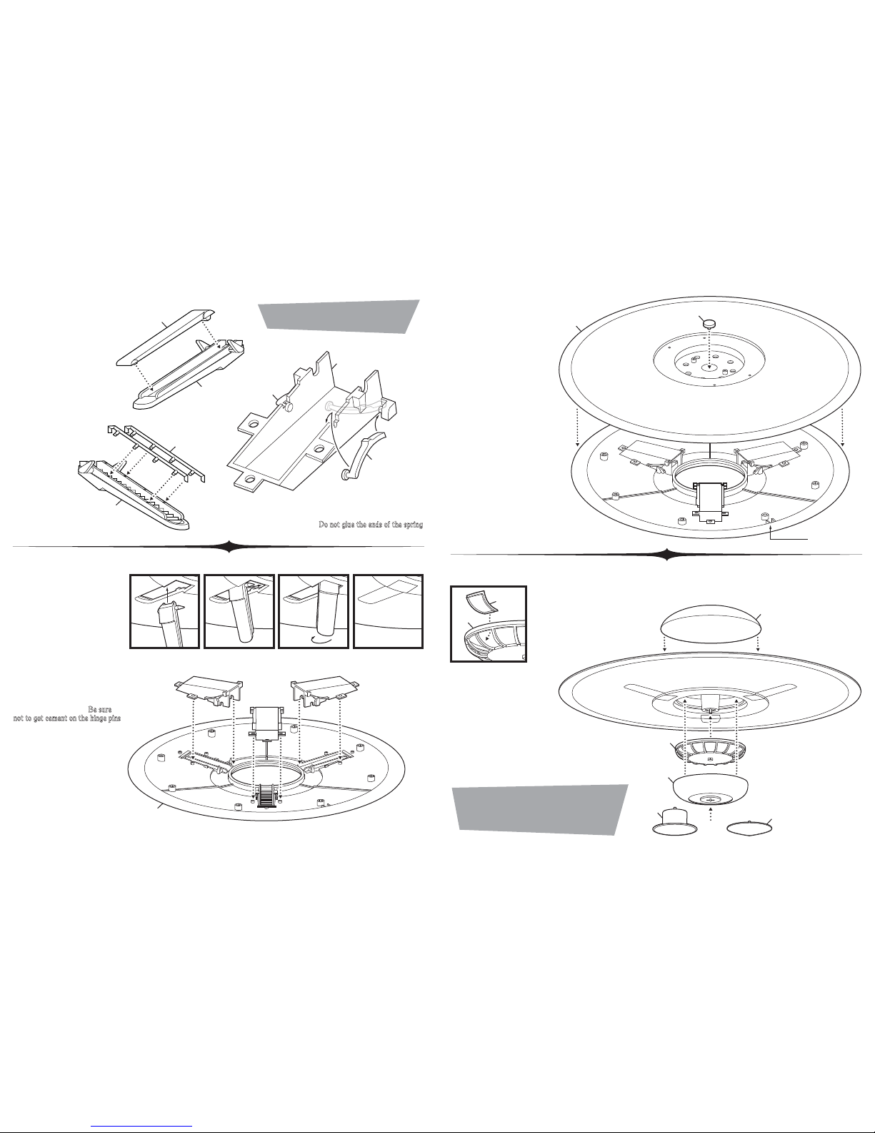
Cement conveyor belt part #10
to ramp part #9.
Paint conveyor flat Dark Gray.
Place engine cage pin part
#5 into the center hole of
upper saucer part #1.
Align the keys in the parts
to orient the saucer
assemblies correctly. Then
cement together.
Paint outer ring of the
saucer a darker shade of
Silver.
Cement engine cage assembly to
the pin in the main assembly.
Cement the lower dome part #19
to the main assembly.
Then cement upper dome part #3 to the assembly.
Glue is optional to hold either the central landing column
part #14 or the lower cap part #15 in place.
Choose part #14 for landed position and use part #15 for
flying position.
If building in flying position, paint part
#4 in Black and paint part #20 in
clear Red. Cement all clear insert
parts #20 to engine cage part #4.
If building in landed position, omit
parts #4 & #20 paint lower dome
part #19 silver to match the rest of
the model.
Place the three ramp assemblies
into lower saucer part #2 by
inserting them through the bottom
of the openings. Push one side into
the corner of the opening and twist
the ramp into place. Once in place,
the ramps should be held in the
closed position when installing
the hallways.
Cement hallway assemblies to the
top of part #2 while trapping the
hinge pins of the ramps. Be sure
not to get cement on the hinge pins.
It is important to glue the areas
closest to the center of the saucer
thoroughly and allow them to dry
completely before moving on in
order to withstand the action of
opening and closing the ramps.
Cement railing parts #7
to stair ramp part #6.
Paint rails Red.
Attach leaf spring parts #12 & #13 to hallway part #11 by
inserting one end into corner as pictured, then flex spring to hang
nailhead end over hallway wall. Do not glue the ends of the spring
.
PAINT NOTE: Unless otherwise stated,
paint all parts BRIGHT SILVER.
NOTE: If desired, a hole can be drilled
into the upper dome to hang the model
by a string (not included). Use the dimple
inside the dome to find the center.
Step 1
10
Step 3
Step 4
Step 2
9
11
12
KEY
OR
13
7
6
2
A
B
C
D
5
3
1
4
4
20
19
14
15
 Loading...