

Polar King Walk-In Series Installation & Service Manual
Installation & Service
Manual
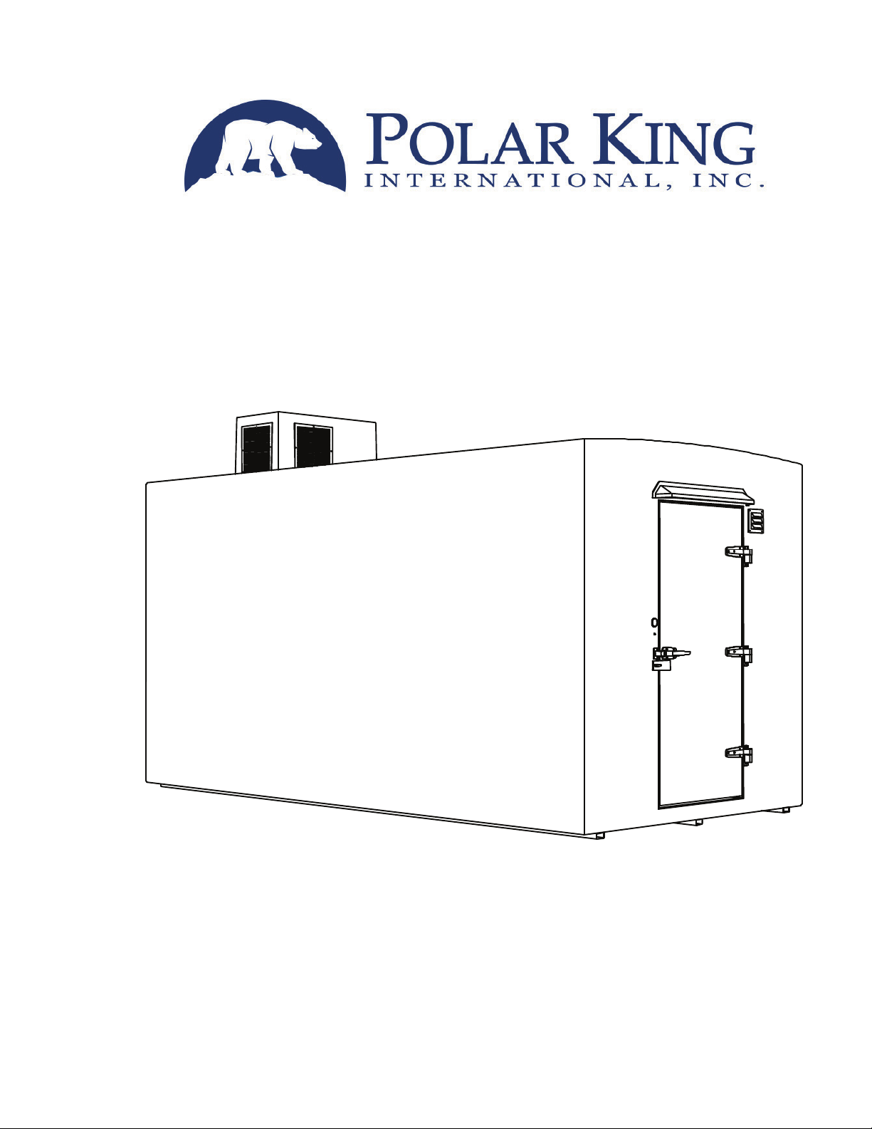
One Piece Outside Walk-In
Coolers - Freezers

Installation & Service
Manual
Polar King International, Inc.
SERVICE
4424 New Haven Avenue
Fort Wayne, Indiana 46803
In Indiana – 260-428-2530
Toll Free – 1-800-223-2017
Fax – 260-428-2533
SALES
4424 New Haven Avenue
Fort Wayne, Indiana 46803
In Indiana – 260-428-2530
Toll Free – 1-800-752-7178
Fax – 260-428-2533

To Our Customers:
Thank you for purchasing a Polar King walk-in to fill your refrigerated
storage requirements.
Your walk-in has been designed and engineered to provide years of
trouble-free service. All Polar King walk-ins are factory constructed using
space-age materials and state-of-the art manufacturing techniques. Every
unit receives numerous quality inspections and is pre-tested prior to
delivery. The finished product is the best and most efficient walk-in
available on the market.
However, should you experience a service problem, please contact our
customer service department. They will work with you on resolving the
problem and insure your continued satisfaction.
Again, thank you for selecting a Polar King. Should you require future
refrigerated storage, we would appreciate the opportunity to serve you.
Polar King International, Inc.
4424 New Haven Avenue; Fort Wayne, Indiana 46803 • 800-752-7178 • 260-428-2530 • FAX: 260-428-2533
www.polarking.com
OUTDOOR WALK-IN COOLERS AND FREEZERS

TABLE OF CONTENTS
Refrigeration Basics ........................................................................................................ 1
Heat Load........................................................................................................................ 1
Product Load................................................................................................................... 2
Loading Your Walk-In...................................................................................................... 2
Basic Structure................................................................................................................ 2
Refrigeration.................................................................................................................... 2
Walk-Through Installation................................................................................................ 2
Installation Instructions.................................................................................................... 3
Roof Flashing Installation ................................................................................................ 4
Sidewall Flashing Installation .......................................................................................... 4
Architectural / Engineering Specifications ....................................................................... 5
Optional Accessories Specifications ............................................................................... 9
Thru-Wall Detail CAT-B1............................................................................................... 11
Height Details CAT-B2 .................................................................................................. 12
Frame Details CAT-B3 .................................................................................................. 13
Curb Detail CAT-B4 ...................................................................................................... 14
Roof Flashing Detail CAT-B5 ........................................................................................ 15
Door Opening Detail CAT-B6 ........................................................................................ 16
Recommended Annual Maintenance ............................................................................ 17
Circuit Breakers............................................................................................................. 17
Allowable Voltages........................................................................................................ 17
Amp Load Requirements And BTUH System Capacities .............................................. 18
Electrical Connections - Single Phase........................................................................... 19
Electrical Connections - Three Phase ........................................................................... 20
Wiring Diagram – Cooler ½ to 2 HP Single Phase ........................................................ 21
Wiring Diagram – Freezer ½ to 2 HP Single Phase ...................................................... 22
Wiring Diagram – Cooler ½ to 2 HP Three Phase......................................................... 23
Wiring Diagram – Freezer ½ to 2 HP Three Phase....................................................... 24
Wiring Diagram – Freezer 3 HP Three Phase............................................................... 25
Sequence Of Operation Coolers and Freezers ............................................................. 26
Defrost (Time Initiated - Temperature Terminated) ....................................................... 27
Defrost Adjustments - Freezer ...................................................................................... 27
Operating Tips............................................................................................................... 29
Service Analysis............................................................................................................ 30
Approvals & Code Compliances.................................................................................... 32
Conditions of Sale ......................................................................................................... 33
Warranty........................................................................................................................35
Warranty Work Policy.................................................................................................... 36
A General Unit Information Sheet is included with this manual for your convenience. This sheet contains
detailed information on your walk-in. Please have this information available when requesting service.

REFRIGERATION BASICS
Modern refrigeration has many applications. The first, and probably the most important, is the
preservation of food because most foods kept at room temperature spoil rapidly. However, when kept
cold most foods will keep much longer.
Before looking at the operation of mechanical refrigeration, it is important to understand the physical and
thermal properties of the mechanisms and substances used to extract heat. Removing heat from the
inside of the walk-in is somewhat like removing water from a leaking boat. A sponge may be used to
soak up the water and then held over the side, squeezed, and the water released overboard. The
operation may be repeated as often as necessary to transfer the water from the boat back into the lake.
In a walk-in, heat instead of water is transferred. Inside the walk-in heat is absorbed by the liquid
refrigerant in the evaporator as the refrigerant changes from a liquid to a vapor. After the refrigerant has
absorbed heat and turned it into a vapor, it is pumped into the condensing unit located outside the
refrigerated space and then compressed. The heat is "squeezed" out by high temperature and then
cooled in the condenser. This cycle repeats until the desired temperature is obtained.
Cold is a relative term used to describe low temperature, it is not something that is produced. Rather, the
removal of heat results in a condition termed “cold”. A refrigerator produces a condition called "cold" by
removing heat from inside the refrigerator and the stored content within it. You have probably felt the
heat on the floor as you walked by your refrigerator in your home. The principle of heat removal is the
same for your walk-in cooler and/or freezer.
The fact that bacteria are present in most foods calls for it to be preserved in some fashion. Exposing the
food to cold or low temperatures slows the growth of these bacteria preventing foods from spoiling as
quickly. A cooler temperature slows the activity of all organisms, thus the growth of bacteria on
refrigerated food slows dramatically.
The spoiling of food is actually the growth of bacteria. If the bacteria can be kept from increasing, the
food will remain edible for a longer period of time. Since most foods contain a considerable amount of
water, the food must be kept slightly above freezing temperatures.
If food is frozen slowly, at or near the freezing point of water, large ice crystals will form and break down
the food tissues. When such food defrosts, it spoils rapidly and the taste and appearance of the food is
greatly compromised. To prevent this problem fast freezing at temperatures between 0° F to -15° F is
recommended. By using these low temperatures small crystals form which do not injure the food tissues.
It is always important to keep in mind the difference between refrigerating and freezing. Further, the
standard walk-in cooler is designed to maintain the temperature of the product at 35° F, providing the
temperature of the product is within 10° F of this temperature. If the product to be maintained is
continually at a higher temperature, additional refrigeration system capacity will probably be required.
The same parameters hold true for freezers.
To insure you have adequate refrigeration capacity, be sure to provide your sales consultant with as
much information as possible about how you intend to use your cooler and/or freezer.
HEAT LOAD
As we mentioned earlier, the refrigeration system on your walk-in does not make things cold. The system
instead removes heat from the walk-in structure. Where does the heat come from that must be removed
by the refrigeration process? The two most common sources you can control are door openings and
product load. Did you know that one 100-watt lamp left on in a walk-in would generate 8,208 BTU in a
24-hour period? Keep door openings and closings to a minimum to conserve energy. When working
inside the walk-in, close the door behind you. No need to worry, as there is a door opener inside.
1

PRODUCT LOAD
The main heat source in your walk-in is the amount of heat that must be removed from the stored
product. For example, if you load your walk-in with 1500 pounds of product at 0° F, very little heat will
have to be removed to obtain a temperature of –10°F. If the same 1500 pounds of product is delivered
from your supplier at +25° F, you must pay to run the refrigeration system to remove this heat from each
and every pound of product, until the satisfactory temperature of –10° F is reached. You will have smaller
utility bills if you let your supplier remove heat from the product, rather than doing it yourself.
Remember, your unit is designed as either a holding unit (little or no product load) or has been designed
to compensate for known product load. It is important to tell your sales consultant how you intend to use
your unit. If significant product load occurs in a unit designed for holding, serious temperature problems
may occur.
LOADING YOUR WALK-IN
Always move product into your walk-in as soon as you receive it. The longer you wait, the more heat it
will absorb and the more you will pay to operate the walk-in. As you load your walk-in, be sure to allow
plenty of airflow around the product because good airflow decreases the amount of time needed to
remove heat. Be sure to allow adequate room around the evaporator. As well, never have a product
closer than 12 to 16 inches to the evaporator. Remember, the evaporator is hot during defrost and can
thaw a product that is too close.
BASIC STRUCTURE
The structure of your walk-in is manufactured at our factory in Fort Wayne, Indiana. Four inch, or optional
six inch, two pound density urethane (the most efficient insulation available) is used in the walls, floor,
and ceiling of the unit. The base of the unit has a built-in steel frame providing tremendous strength and
allows for easy movement or total portability should your needs require this flexibility.
The unit is completely encased in fiberglass...one continuous surface... which means no seams, no rivet
holes, and no air leaks. Unlike other outdoor units, you will never have to caulk splits or metal tears in
your Polar King walk-in. No protective roofs or enclosures are required. You won't pay to "cool the
outside" with a Polar King unit. All the cold air stays in the unit where it belongs. This equates to big
dollar savings for you.
REFRIGERATION
Copeland Condensing Units and Larkin Evaporators are used to give you one of the finest refrigeration
systems available. Every system is engineered to provide maximum operating efficiency and years of
trouble-free operation. All units are adjusted to the customer's temperature requirements. Trained
technicians test and monitor the performance of each unit for 24 hours prior to it’s leaving our factory.
WALK-THROUGH INSTALLATION
Polar King walk-ins are designed for exterior installation. Units are delivered ready to run as "free
standing" units. However, many customers use walk-through installation. This provides the same
convenience as an inside installation without taking up valuable and costly interior floor space.
Drawings are provided that detail slab elevations, dimensions for walk-through opening, and the flashing
detail.
Should you have any questions on a walk-through installation, please feel free to contact our sales or
engineering departments.
2

INSTALLATION INSTRUCTIONS
Polar King walk-in coolers and / or freezers are delivered to our customers fully assembled and require
only a few basic procedures prior to start-up.
DO'S
(1) Provide a level slab as required by your local building code. It is very important that the surface is
level for proper drainage and operation. See Section 3 "Technical Information" for walk-through
applications where walk-in unit is to be attached to the building.
(2) Condensing unit on the top (or back) of the walk-in should be a minimum of 6 feet from any
building intake or exhaust ventilation fans.
(3) Keep an open area of at least 3 feet around condensing unit to assure that sufficient air ventilates
across the compressor.
(4) Make sure you have adequate electrical service for your particular unit.
(5) Once walk-in is in place, a qualified electrician in accordance with the NEC and / or local
electrical codes may then wire it. A wiring diagram is located on the backside of the electrical box
panel on the condensing unit.
(6) Loosen compressor-mounting bolts (if supplied).
(7) Set the correct time of day on the defrost timer. This is necessary in order for the preset defrost to
occur at the desired times.
(8) If unit is delivered or sits idle in winter months, an external heat source should be applied to the
compressor crankcase for 12 to 24 hours prior to start-up.
(9) The unit is now ready for operation. (See sequence of operation; Section 5 "Operating
Instructions")
(10) Units are preset at the factory to automatically include four defrost cycles for a duration of 30
minutes each. Preset defrost cycles may be changed to accommodate different applications.
DON'TS
(1) Do not physically alter any controls, switches, wires, or any device carrying an electrical current,
without disconnecting power to the walk-in cooler and/or freezer.
(2) The box temperature is preset at the factory to customer request. Temperature selection should
not be adjusted up or down. If a different temperature is required, contact Polar King for proper
procedure on changing the preset temperature.
(3) When cleaning the inside of the unit with any liquid substance, turn off electrical power.
IMPORTANT: DO NOT USE BLEACH OR AMMONIA TO CLEAN INSIDE OF UNIT AS IT MAY
CAUSE DAMAGE TO COIL SURFACE.
(4) IMPORTANT: DO NOT DISCONNECT MAIN POWER SUPPLY WHILE COMPRESSOR IS
RUNNING. DAMAGE MAY OCCUR IF COMPRESSOR IS NOT ALLOWED TO PUMP DOWN.
3

ROOF FLASHING INSTALLATION
(1) Read instructions thoroughly before starting. Take inventory of necessary materials. Items
provided by Polar King includes:
a. Elastoform flashing (12” wide rubber material) (The front side has a plastic film covering
that can be removed after installation and the back side is uncovered.)
b. 45° cant strip (fillet strip)
c. Splice adhesive (Firestone SA-1065 or equivalent)
d. Pre-drilled aluminum termination bar
(2) Additional items needed:
a. Mechanical fasteners (screws or other type of fastener) for termination bar.
b. Silicone sealant.
(3) See Flashing Detail CAT-B5 for approximate placement of materials.
(4) Be sure roof of walk-in is free of dust and dirt to a distance of 12” from building.
(5) Place cant strips against building as shown on detail.
(6) Apply a coat of splice adhesive that is approximately 5” wide to the roof of your walk-in and the
wall of your building.
(7) Apply a coat of splice adhesive to back side of elastoform flashing. Allow adhesive to set long
enough to get tacky.
(8) Place flashing face up onto the coated area of the roof and wall, while keeping it centered on the
cant strip.
(9) Apply pressure to the flashing to be sure that there is a good bond against the roof and the wall.
At this point the film cover on the front side can be removed.
(10) Install supplied termination bar over top edge of elastoform flashing. Fasten approximately 12”
on center. (Fasteners are not included.)
(11) Apply bead of silicone sealant (not provided by Polar King) to top of termination bar to finish
installation. The completed flashing assembly can be painted if desired.
SIDEWALL FLASHING INSTALLATION
(1) Read instructions thoroughly before starting. Take inventory of necessary materials. Items
provided by Polar King includes:
a. PVC flashing (1” x 5” ell shape PVC material)
(2) Additional items needed:
a. Mechanical fasteners (screws or rivets)
b. Construction adhesive.
c. Silicone sealant.
(3) Align PVC flashing against building and walk-in and trim for proper fit. Flashing may be applied
with short leg sticking out or in.
(4) Flashing can be attached to walk-in using any heavy-duty construction adhesive.
(5) Use sheet metal screws to hold in place until adhesive sets.
(6) Apply bead of silicone sealant to finish installation.
4

ARCHITECTURAL / ENGINEERING SPECIFICATIONS
The following specifications are designed for use as a guide to Architectural, Engineering, and Food
Service Consultant specification writers, on projects utilizing outdoor walk-in refrigeration equipment.
Where items appear in brackets [ ] a selection of one of the alternatives is required by the specifier. Due
to our policy of ongoing product improvement, Polar King International reserves the right to change
specifications without notice.
1.0 GENERAL
1.1 The equipment provided shall be factory prefabricated and have unitized design. The equipment
will allow installation without assembly and relocation without disassembly. The equipment shall
require an on-site contractor, responsible for pouring of concrete pad, connection of electrical
power supply to each refrigeration system, and for flashing of unit to building wall (if required).
Walk-in shall be Polar King (Polar King International, Inc., Fort Wayne, Indiana) Model
No.__________.
1.2 The walk-in shall bear the label of the following National Certification Agencies:
A. National Sanitation Foundation (NSF STD #7)
B. Underwriters Laboratory (Major Refrigeration Components)
C. Underwriters Laboratory (Major Electrical Components)
D. Underwriters Laboratory (Class I Urethane)
1.3 The walk-in shall comply with the following model building codes:
A. International Conference of Building Officials (ICSO)
B. Southern Building Code Congress International (SBCCI)
C. Building Officials Congress Association (BOCA)
D. National Electric Code (NEC)
2.0 SIZE AND CAPACITY
2.1 The walk-in shall be built to specified interior and exterior dimensions, as shown on the plans and
drawings.
2.2 The walk-in shall have sufficient refrigeration to maintain [+35° F] [0° F] [-10°F] [-20° F]
temperature inside the [cooler] [freezer] compartment when the ambient temperature is 100° F,
the average number of door openings is [1] [2] [3] [4] [10] per hour, and there is [no]
[____BTUH] load from warm products entering unit. The refrigeration system shall be wired to
run on [208V/60HZ/1PH] [230V/60HZ/1PH] [208-230V/60HZ/3PH] power.
3.0 STRUCTURE
3.1 The walk-in structure shall be constructed with a fiberglass interior and exterior and a 4" urethane
core. The interior and exterior fiberglass shell shall be completely seamless and will form a onepiece structure. The exterior shall be rust, dent and scratch resistant. The exterior shall be
coated with an industrial enamel finish.
3.2 Partition walls shall be constructed in the same manner as the exterior walls with a 4" urethane
core.
5

4.0 FLOOR
4.1 A 4" insulated (R-32) prefabricated floor shall be supplied. The floor shall be reinforced with
woven fiberglass matting on top of a 1/2" sub floor bonded to the urethane core forming a
watertight seal. A skid resistant surface coating will be applied to the floor surface. The floor
shall be constructed for permanent elevation 11/2" above grade. The elevation provides for air
circulation under the floor to eliminate corrosion and the need for an insulated and / or ventilated
slab. A welded, heavy-duty steel frame shall be encased in fiberglass and permanently bonded
to the floor to ensure total portability without damage to the walk-in. The floor shall have the
capacity to support 900 Ibs. / sq. ft. of evenly distributed load.
5.0 INSULATION
5.1 All insulation shall be minimum 4" thick rigid polyurethane foam chemically bonded to the interior
and exterior fiberglass to form a one-piece structure.
5.2 The thermal conductivity (K) shall not exceed .125 (BTU's/in/sq. ft./hr. F). The thermal resistance
(R) factor shall not be less than 32.
5.3 The insulation shall be U.L. Class I having a flame spread of not more than 25, fuel contributed of
0, and smoke developed of 170.
6.0 LIGHTING
6.1 Unit shall be complete with [incandescent] [fluorescent] light fixtures factory installed and
tested for proper operation prior to shipment. A [100 watt incandescent bulb] shall be used for
each 50 sq. ft. of interior floor space. A [four foot, two bulb fluorescent fixture] shall be used
for each 100 sq. ft. of interior floor space. Lights shall be contained in a vapor-proof fixture.
7.0 DOORS
7.1 Doors shall be constructed in the same manner as the walls with no less than 4 inches of
urethane insulation.
7.2 All doors opening into a controlled temperature room shall be supplied with doorframe heaters,
which shall supply sufficient heat to prevent condensation or frost accumulation.
7.3 Doors shall be provided with a magnetic gasket around the perimeter. Flush bottom doors shall
be provided with adjustable vinyl sweep gasket. When door is closed, it shall form a positive
airtight seal. Door gasket shall be installed in retainer strips for easy replacement in the field.
7.4 Doors shall incorporate a positive snap action latch with adjustable strike. The latch shall be
equipped with cylinder lock and OSHA approved inside safety release mechanism to prevent
entrapment. The hardware shall be chrome finished and mounted with stainless steel tamperproof screws.
7.5 Doors shall be equipped with three heavy-duty strap type door hinges. They shall be cam lift
type, self-closing, with nylon bearings and door lift-off capability. Hardware shall be chrome
finish.
7.6 Doors shall be hinged as shown on the drawings.
7.7 The following doors are required in the location as shown on the plans and drawings.
Standard Entry Doors Optional Entry Doors Product Loading Doors Service Doors
A. [30" x 79"] A. [48" x 79"] A. [24" x 24"] A. [36" x 80"]
B. [36" x 79"] B. [54" x 79"] B. [24" x 30"] B. [36" x 84"]
]"48 x "24[ .C ]"03 x "03[ .C ]"97 x "06[ .C
]"48 x "84[ .D
6

7.8 Entry doorjamb shall include a vapor-proof switch and visible pilot light to indicate when lights are
in the "ON" position.
8.0 THERMOMETER
8.1 Entry door shall be supplied with 2", flush face dial-type thermometer. Thermometer shall be NSF
approved.
9.0 HASP LOCK
9.1 All entry doors not specified as thru-wall or partition type doors shall be equipped with a door
hasp lock to prevent unauthorized entry into the walk-in. The hasp lock shall be supplied with an
inside safety release mechanism.
10.0 DOOR WEATHER HOOD
10.1 A weather hood shall be supplied on all exterior doors.
10.2 The weather hood shall act to divert rain and ice from gasket area of all exterior doors. It shall
match exterior wall finish and shall be factory mounted.
11.0 OPTIONAL ACCESSORIES
11.1 The following optional accessories are to be provided with the walk-in and shall be factory
installed.
[11.2 Exterior Door Ramp] [11.15 Remote Refrigeration Mounting]
[11.3 18 ga. Stainless Steel Door Kick Plate Set] [11.16 Nailer Trim]
[11.4 Door Closer (Hydraulic Arm Type)] [11.17 Refrigeration System Switch]
[11.5 Burglar Alarm System] [11.18 Wire / Solid Shelving]
[11.6 Strip Door Curtain] [11.19 Floor Drain]
[11.7 Framed Wall Opening] [11.20 Steel Service Door]
[11.8 Merchandising Doors] [11.21 Hurricane Anchors]
[11.9 Temperature Alarm] [11.22 Exterior Flood Light]
[11.10 Temperature and / or Humidity Recorder] [11.23 Extra Heavy Duty Sealed Floor]
[11.11 Explosion Proof (Class I) Electrical System] [11.24 Custom Exterior Finishes]
[11.12 Fluorescent Lighting] [11.25 Supplementary Compartment Heaters]
[11.13 Three-Way Light Switches] [11.26 Full Bar Security Hasp Lock]
[11.14 Pressure Relief Vent] [11.27 Through Wall Door Threshold]
7

12.0 SELF CONTAINED REFRIGERATION SYSTEM(S)
12.1 Packaged refrigeration system(s) shall be manufactured and factory installed by the walk-in unit
manufacturer.
12.2 System(s) shall be complete and ready to operate without field assembly, installation, or start-up
required.
12.3 Refrigerants shall be non-flammable type R-404a or other acceptable substitute when necessary.
12.4 Electrical controls including system breakers shall be supplied, installed and ready to operate with
single point electrical connection by others.
12.5 Refrigeration system(s) shall be complete with the following: roof mount type horizontal
discharge air cooled condenser, Copeland hermetic (or equal) and semi-hermetic compressor (or equal)
with overload protection and contactors (as required), weather hood finished to match exterior
wall finish, fan guards, receiver tank with liquid shut off valve, suction line accumulator (on 3 HP
systems and higher only), liquid line filter / drier and sight glass, high / low pressure control, liquid
line solenoid valve, crankcase heater, low ambient controls to -20° F, room thermostat and U.L.
labeled electrical control panel wired in accordance with N.E.C. standards.
12.6 Evaporator coils shall be furnished with appropriate defrost for operating temperature range.
12.7 Electric defrost shall be included on all refrigeration systems operating at +32° F and below.
Electric defrost shall be time initiated and temperature terminated with time override and fan
delay to reduce room condensation. All condensate pans shall be piped to copper drain line
complete with heat tape exiting the wall nearest to drain pan. Evaporators shall be located as
shown on plans and drawings.
12.8 Refrigeration systems operating at +33° F and above shall be off-cycle air defrost. Defrost
periods shall be time initiated and time terminated. All condensate pans shall be piped to PVC
drain line exiting the wall nearest to drain pan. Evaporators shall be located as shown on plans
and drawings.
13.0 PRESSURE RELIEF VENT
13.1 All freezer compartments shall be supplied with a heated pressure relief vent. It shall include
interior and exterior covers, 120V/60HZ/1PH antifreeze heater assembly, closable damper
assembly to close when not venting and a PVC sleeve to protect urethane foam in wall structure.
8
 Loading...