

Polaris Scientific UV-1, UV-2, UV-6, UV-8C, UV-12C Installation Instructions & Owner's Manual
...
RRoHoHSS
CCOOMMPLPLIIANANTT
Your best choice in Ultraviolet Sterilization
For models: UV-1, UV-2, UV-6, UV-8C, UV-12C, UV-24B UV-100B
Ultraviolet Sterilization System
Installation Instructions
& Owner’s Manual
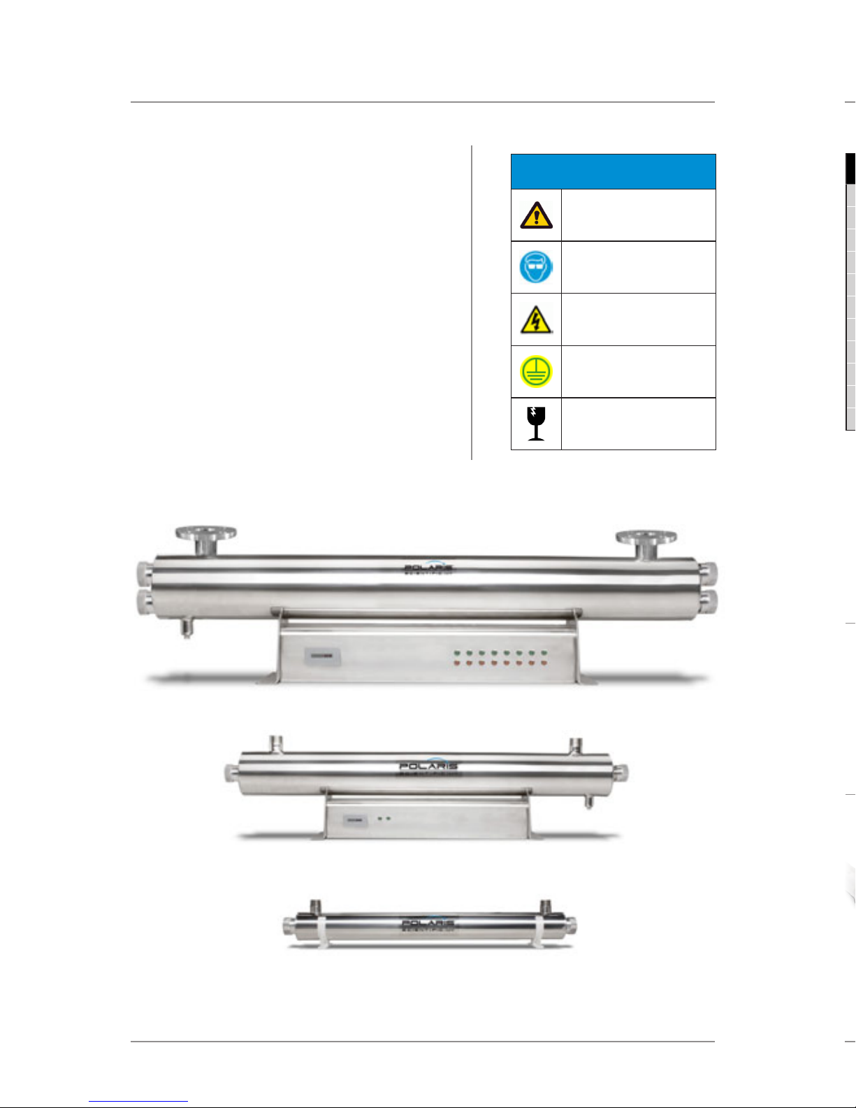
TABLE OF CONTENTS PARTS & ACCESSORIES
Part
Number
Lamp
UV-1C
GL10SE4P QS 10 EB-1024 UV-NUT-1 - - UV-SEAL UV-PLUG
UV-2C GL14SE4P QS 14 EB-1024 UV-NUT-1 - - UV-SEAL UV-PLUG
UV-6C GL24SE4P QS 24 EB-2439 UV-NUT-1/UV-NUT-2 - - UV-SEAL UV-PLUG
UV-8C GL39SE4P QS 32 EB-2439 UV-NUT-1/UV-NUT-2 UV-32 SPRING - UV-SEAL UV-PLUG
UV-12C GL39SE4P QS 39 EB-2439 UV-NUT-1/UV-NUT-2 UV-39 SPRING - UV-SEAL UV-PLUG
UV-24B GL39SE4P QS 39 EB-2439 UV-NUT-1/UV-NUT-2 UV-39 SPRING UV-TIMER UV-SEAL UV-PLUG
UV-36B GL39SE4P QS 39 EB-2439 UV-NUT-1/UV-NUT-2 UV-39 SPRING UV-TIMER UV-SEAL UV-PLUG
UV-50B GL39SE4P QS 39 EB-2439 UV-NUT-1/UV-NUT-2 UV-39 SPRING UV-TIMER UV-SEAL UV-PLUG
UV-60B GL39SE4P QS 39 EB-2439 UV-NUT-1/UV-NUT-2 UV-39 SPRING UV-TIMER UV-SEAL UV-PLUG
UV-80B GL39SE4P QS 39 EB-2439 UV-NUT-1/UV-NUT-2 UV-39 SPRING UV-TIMER UV-SEAL UV-PLUG
UV-100B
GL39SE4P QS 39 EB-2439 UV-NUT-1/UV-NUT-2 UV-39 SPRING UV-TIMER UV-SEAL UV-PLUG
Safety Instructions ..................................... 1
Operation & Maintenance ......................... 2-3
Warning Systems ......................................... 4
Installation ..................................................... 5-6
Troubleshooting Guide .............................. 6-7
Water Chemistry ........................................... 7
Warranty Information ................................. 8
Parts & Accessories ...................................... 9
Product Specications ................................ 10
CAUTION
EYE PROTECTION
ELECTRICAL WARNING
PROTECTIVE GROUND
FRAGILE
LEGEND
UV-8C
UV-24B
UV-32SPRING
Stainless Steel Spring
for Model UV-8C
UV-NUT-1
Stainless Steel Long Nut
for Wire Connection
for Models UV-1C – UV-100B
UV-100B
WARNING - to guard against injury, basic safety precautions should be
observed, including the following:
1. READ AND FOLLOW ALL SAFETY INSTRUCTIONS.
2. CAUTION - Disconnect power before servicing.
3. DANGER - To avoid possible electric shock, special care should be taken
since water is present near electrical equipment. Unless a situation is
encountered that is explicitly addressed by the provided maintenance
and troubleshooting sections, do not attempt repairs yourself, refer to an
authorized service technitian.
4. Carefully examine the disinfection system after installation. It should not be
plugged in if there is water on parts not intended to be wet.
5. Do not operate the disinfection system if it has a damaged cord or plug, if it
is malfunctioning or if it is dropped or damaged in any manner.
6. Always disconnect water ow and unplug the disinfection system before
performing cleaning or maintenance activities. Never yank the cord to
remove from an outlet; grasp the wall plug and pull to disconnect.
7. Do not use this disinfection system for other than intended use (potable
water applications). The use of attachments not recommended or sold by
the manufacturer/distributor may cause an unsafe condition.
8. Intended for indoor use only. Do not install this disinfection system where
it will be exposed to the weather or to temperatures below freezing. Do not
store this disinfection system where it will be exposed to the weather. Do
not store this disinfection system where it will be exposed to temperatures
below freezing unless all water has been drained form it and the water
supply has been disconnected.
9. Read and observe all the important notices and warnings on the water
disinfection system.
10. If an extension cord is necessary, a cord with a proper rating should be used.
A cord rated for less Amperes or Watts than the disinfection system rating
may overheat. Care should be taken to arrange the cord so that it will not be
ripped over or pulled.
11. SAVE THESE INSTRUCTIONS.
WARNING: The UV light given o by this unit can cause serious burns to
unprotected eyes and skin. Never look directly at an illuminated UV lamp. When
performing any work on the UV disinfection system always unplug the unit rst.
Never operate the UV system while the UV lamp is outside of the UV chamber.
Note: The UV lamp inside of the disinfection system is rated at an eective life of approximately 9000
hours. To ensure continuous protection, replace the UV lamp annually.

Page 2 Page 7
OPERATION & MAINTENANCE INSTRUCTIONS TROUBLESHOOTING GUIDE & WATER CHEMISTRY
• Always disconnect power before performing any work on the
ultraviolet disinfection system.
• Regularly inspect your disinfection system unit to ensure the UV light
is still glowing.
• Replace the UV lamp annually (or biennially if seasonal use) to ensure
a high bacteria and virus kill rate.
• Always drain the UV system when closing a cabin/cottage or leaving
the unit in an area subject to freezing temperatures.
A. UV Lamp Replacement
To replace the lamp, there is NO need to disconnect the system from the water supply,
nor to drain the water from the reactor chamber. Lamp replacement is a quick and
simple procedure requiring no special tools. The UV lamp must be replaced after
9,000 hours of continuous operation (approximately one year) in order to ensure
adequate disinfection.
UV1, UV2, UV6, UV8C, UV12C, UV24B UV100B
1. Disconnect main power source and allow the unit to power down. Remove the
lamp connector by sliding the metal retaining ring away from the body of the
connector. Remove the lamp form the reactor chamber. Separate the lamp from
the connector. Do not twist the lamp from the connector, simply slide the two
apart. Avoid touching the lamp on the glass portion. Handling the lamp at the
ceramic ends is acceptable, however if you must touch the lamp glass, please use
gloves, or soft cloth. Fully remove the lamp from the reactor chamber being careful
not to angle the lamp as it is removed from the chamber. If the lamp is removed
on an angle, pressure will be applied on the inside of the quartz sleeve, causing
the sleeve to fracture.
2. To install a new lamp, rst remove the lamp from its protective packaging, again
being careful not to touch the lamp glass itself. Carefully insert the lamp into the
reactor vessel (actually inside the quartz sleeve). Insert the lamp fully into the
chamber leaving about two inches of the lamp protruding from the chamber.
Next, attach the connector to the UV lamp. The connector is “keyed” and will only
allow correct installation in one position. Ensure the connector is fully seated onto
the UV lamp.
3. Once the lamp is fully seated on the connector, slide the connector over the
aluminum retaining nut. Make sure the metal retaining ring on the connector is
pulled away from the body of the connector in order that the connector may slide
fully over the retaining nut. Once the connector is located fully over the retaining
nut, slide the metal ring back into lock the connector in place. As this connector
is keyed to the reactor chamber, make sure the depression on the connector
is located over the ground lug located on the reactor chamber.
LAMP STATUS
(GREEN LED)
ON OFF ON
OFF ON OFF
OFF OFF ON
Water quality is extremely important for the optimum performance of your UV system.
The following levels are recommended for installation:
• Iron:<0.3 ppm (0.3 mg/L)
• Hardness *:< 7 gpg (120 mg/L)
• Turbidity: < 1 NTU
• Manganese: < 0.05 ppm (0.05 mg/L)
• Tannins: < 0.1 ppm (0.1 mg/L)
• UV Transmittance: > 75%
(Call factory for recommendations on applications where UVT < 75%)
* Where total hardness is less than 7 gpg, the UV unit should operate eciently provided the quartz sleeve is cleaned
periodically. If total hardness is over 7 gpg, the water should be softened.
If your water chemistry contains levels in excess of those mentioned above, proper
pre-treatment is recommended to correct these water problems prior to the installation
of your UV disinfection system. These water quality parameters can be tested by your local
dealer, or by most private analytical laboratories. Proper pre-treatment is essential for the UV
disinfection system to operate as intended.
 Loading...