

Page 1
Page
1
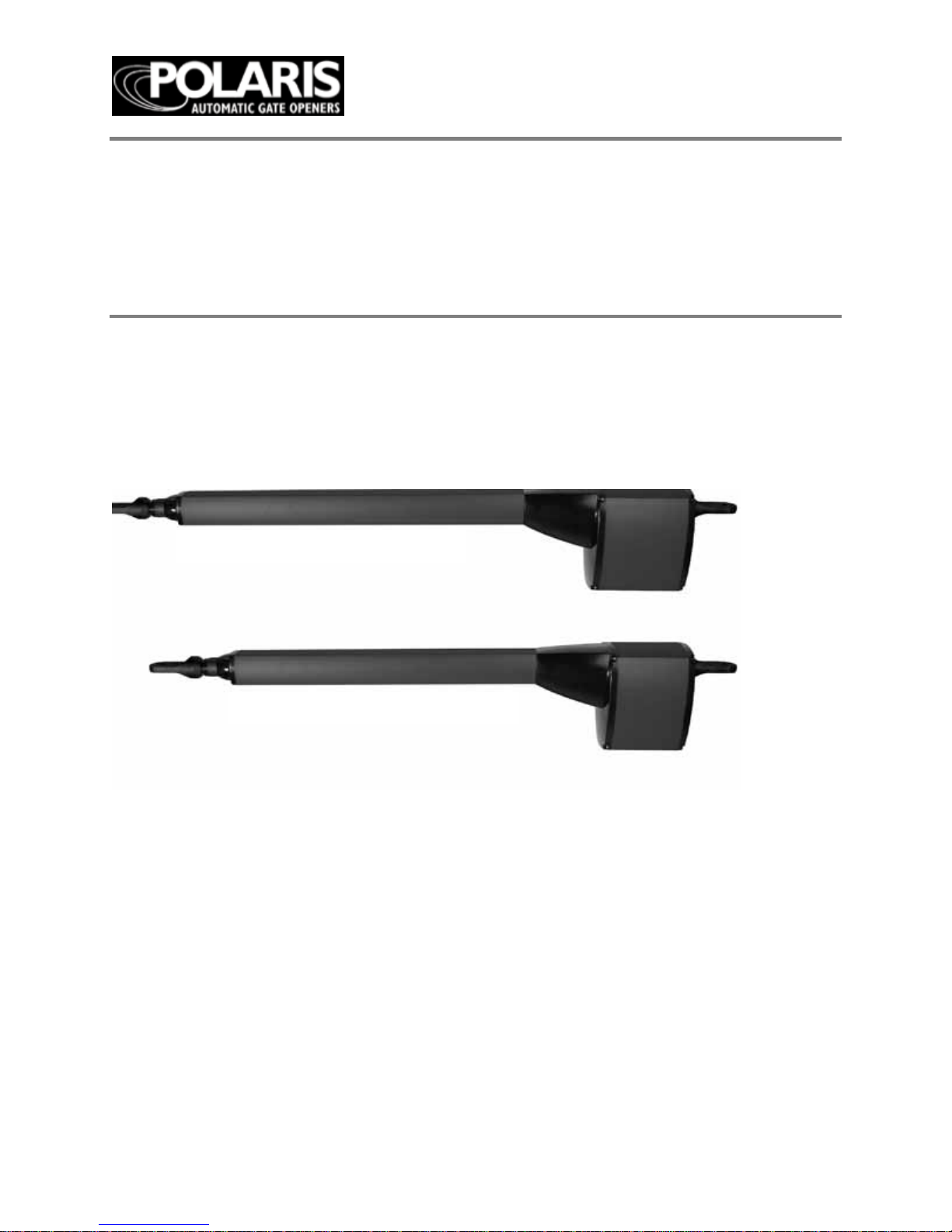
User Manual 500 & 700 Single
500/502 & 700/702 Dual
Warning: Before installing your Polaris
Automatic Gate operator (som etim e s also
referred to as the “Product”), read this entire
Installation Manual for information about Product
safety matters and proper use of the Product.
Only use the Product for the purpose of
operating a driveway gate.
Polaris 700/702
Polaris 500/502
Page 2

Page
2
Document revision: 1.1
Table of Contents
Gate Operator Class Categories ........................................................................... 4
Warnings and Precautions .................................................................................... 5
Installing The Polaris Operator(s)
................................
................................
......... 8
Pull-to-Open Gate Operat or Mounting
................................
................................
... 9
Push-to-O pen Gate Operator Mounting............................................................... 11
Post Mount Brackets
................................
................................
...........................
13
Circuit Board Diagram
................................
................................
.........................
16
Board Layout Des c ription ...................................................................................
16
Di p Sw i tc h e s ........................................................................................................
17
Wiring Operator
................................................................................................... 18
Pull-to-Open L im it S e tting ................................................................................... 22
Push-to-Op e n Li m i t Se ttin g ................................................................................. 24
Primary/Secondary Gate Movement .................................................................... 26
Obstruction Sensitivity Set Up
................................
................................
............ 27
Auto Close Timer ................................................................................................. 28
Transmitter/Receiver ................................................................
...........................
29
Accessory Hook Up Diagram .............................................................................. 30
Exit Wand Hook Up Diagram ............................................................................... 33
Photo Eyes Hook Up Diagram ............................................................................. 34
Emergency Disconnect .......................................................................................
36
Technical Specifications ..................................................................................... 37
Parts List and Illustrations .................................................................................. 38
Troubleshooting/Maintenance .............................................................................
40
List of Accessories .............................................................................................. 42
Warranty .............................................................................................................. 43
Polaris Automatic Gate Operators
8617 Paseo Alameda NE
Albuquerque, NM 87113
Phone: 877-313-8902
Fax: 800-830-3952
Email: ask@polarisgate.com
Web: ww w.p olarisgate.com
Page 3
Page
3
WARNING OF RISKS, PURCHASER’S RESPONSIBILITIES, AND ASSUMPTION OF
CE RT A IN R ISK S :
The directio ns for installation and use of the Product must be followed carefully. It is
imp ossible to eliminate all risks inherently associated with use of the Product. The
effectiveness of the Polaris Automati c Gate Operator depend s on pro
per installation and
the manner of use or application, all of which are beyond the control of Polaris Professional
Products or the seller. All such risks are assumed by the purchaser, and by the purchaser’s
installation and use of the Product.
The Polaris Automatic Gate Operator is for use on driveway gates only. The Product meets
or exceeds the requirements of UL 325, the standard that regulates gate operator safety, as
established and m ade effective March 14, 2003, by Underw riters Laboratories, Inc.
Page 4

Page
4
Gate Op erato r Class C ategories
Ga te o pe ra to r CLA S S C AT EGOR I E S *
The Polaris Autom ati c Gate Operator is intended for use with vehicular swing gates. The
operator can be used in Class I and Class II applications.
Residential V ehicular G ate Opener–Class I: A vehi cular gate opener (or system) intended
for use in a home of one-to-four single family dwelling, or a garage or parking area
associated therewith.
Light Commercial/General Access Vehicular Gate Opener Class II: A vehicular gate
opener (or system) intended for use in a commercial location or building such as a
multifamily housing unit (five or less single family units), hotel, garages, retail store or
other building servicin g the general public.
Industrial/Limited Access Vehicular Gate Opener–Class III:
A vehicular ga te opener (or system) intended for use in an industrial location or building
such as a factory or loading dock area or other locations not intended to service the general
public.
Restricted Access Vehicular Gate Opener–C l a ss IV: A
vehicular g ate opener (or system) intended for use in a guarded industrial location or
building such as an airport security area or other restricted access locations not servicing
the general public, in which unauthori zed access is prevented via supervision by security
personnel.
*Categories establi shed by Underw ri ters Laboratories for vehicle gate operators
Polaris is a high end residential gate operator. Also suited for light commercial
applications. Not advised for continuous duty.
GATE OPERATOR CLASS CATEGORIES
FOR YOUR RECORDS
Please record the serial numb er
(found on the control box cover)
and purchase information below.
Keep this with your proof of purchase
(receipts) in case your product is lost, stolen
or requires service.
Serial number: _______________________
Purchase date: ____________________
Retailer/store name: __________________
Custom er Servi ce
8:00am to 5:00pm, MST, Monday – Friday
Polaris Gate Operators
8617 Paseo Alameda NE
Albuquerque, NM 87113
Phone: 877-313-8902 Fax: 800-830-3952
Email: techsupport@polarisgate.com
Page 5

Page
5
Warn ings an d Precau tion s
General Safety Information
The Pola ris A uto ma tic Gat e Oper ator is des ign ed to
pro vide for sa fe opera tio n. One of th e most imp ort ant
safet y feat ure s of the gate oper ator is obs tru ct ion
sen sing. Wh e n there is an obst ruc tio n that pre vent s
the gate from opening or closing, the gate will
imm ed iately re ver s e directio n and re turn to the f ull y
open or clo s e d pos ition. W hile in t he proce ss o f
return ing to th e fully op en or clo sed posit io n, if the
gate senses an additional obstruction the gate will
sto p imm e d iat e ly a nd so u nd an a larm. At th is point
the gate operator will need to be reset by turning the
power switch on the control box OFF for a minimum
of ten seco nds.
The Polaris gate operator includes an adjustment for
setting the sensitivity of the obstruction performance.
Refer to page 27 fo
r O bstruction Se nsitiv ity Set Up
details.
Vehicular gates are large heavy objects. Polaris
Automatic gate operators provide a convenient way
to open and clo se the ga tes. S ince th e gate syste m an d
its com pon ent s exert a high le vel of forc e to open and
close the gat e, they can be da nge rou s, cau sin g sever e
injur ies or dea th to you and ot her s.
Your saf et y and the safe ty of othe rs dep end on th e
insta ller of this sys te m to read, und er sta nd, and
follow the information and instructions in this
manual.
The P ola r is Automatic Gate Operator is designed to
comply with UL 325, the safety standard covering
automatic gate opening systems. UL 325 requires that
gate opening systems have provisions for, or be
supplied with, at least one independent primary and
one independent secondary means of protection
again st ent rap me nt. The pr imar y me ans of
entr a p me nt pr o te c tion in th e Po la r is A uto m a tic
Gat e Op er at or is Typ e A, an in her en t m ean s of
entra pm ent pr ote ction. The sec on dar y mean s of
entr a p me nt pr o te c tion in th e Po la r is A uto m a tic Gate
Operator is Type B1, the provision for the connection
of a photo cell or othe r non con tac t senso r
The gate op era tor’ s bui lt-in means of entrapment
prote ct ion (T ype A) ma y not be sens itive e nou gh to
prevent bodily injury in some circumstances.
Secondary means of entrapment protection (Type
B1), su ch as a photo cell are su gge ste d for enh anc ed
safety.
Safety overview check list:
WARNING
– To reduc e the ris k of inj ury or death:
• S AVE T HESE INSTRUCT IONS
•
U se this oper ator on ly with s win g gate s.
• RE AD AND FOL LOW ALL INSTR UCT IONS.
• Ne ver let ch ildre n op erat e or play with ga te
controls.
• Keep the remote control away from children.
• Always keep people and objects away from the
gate.
• NO O NE SHO ULD CROS S T HE PATH OF
THE MOVING GATE.
• The e ntr anc e is for vehic les
only. Pedestrians
mu st use a separate ent ran ce.
• Remember that the Polaris Automatic Gate
Operator must only be installed on gate
systems meeting the requirements of the
application.
• Ensur e t ha t you are usin g the c or rect ga t e
operator f or t he typ e
a nd size
of gate, it s
frequenc y of us e a nd the class rating.
• Ensure that the gate and gate operator
installation comply with applicable
local codes.
• Cont act local fire and law enforcement to
arrange emergency access procedures.
• Keep people, animals, and property away
from the gate area. Do not let children
play in or near the gate area.
• Use caution with moving parts to avoid
injuring fingers or hands.
• Consider installing contact sensors, or
non-contact sensors to provide
additional safety and protection against
entrapment.
• Never activate the gate operator until you
ensure that the area is clear of people,
pets, or other obstructions.
• Watch the gate until it stops.
• Controls must be far enough from the
gate so that the user is prevented from
coming in contact with the gate while
operating the controls.
Page 6
Page
6
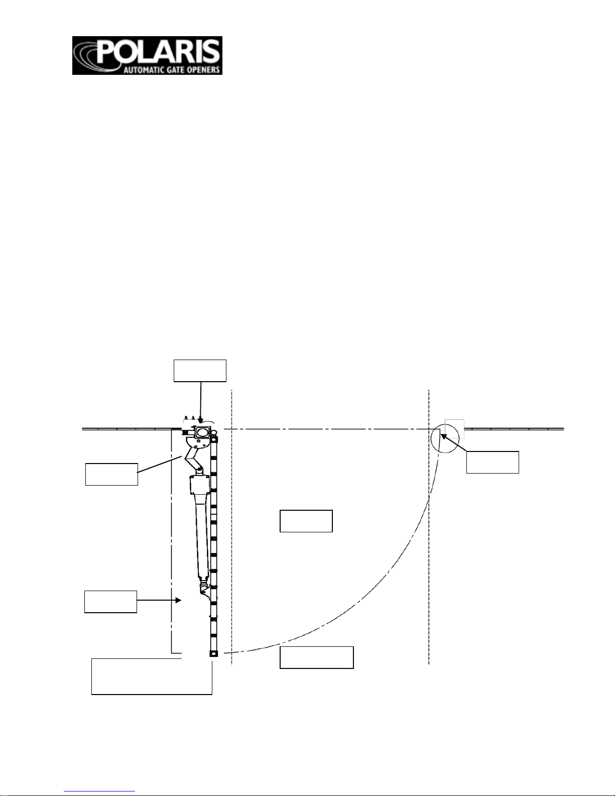
Protection against Entrapment
Important! Study
the figure below
and keep safety foremost at all
times.
Entrapm ent areas for a proper pull-to-open installation
Entrapm ent A rea 1
Hing ed edge of the gate and the fence post
Entrapm ent A rea 2
Between the gate and the gate post
Entrapm ent A rea 3
The p ath o f th e g ate
Entrapm ent A rea 4
The space betw een the gate in the open position and
any object such as a wall, fence, tree, etc.
Entrapm ent A rea 5
Pin
ch points between the operator and gate or post
Area 2
Area 1
Area 3
Area 4
Area 5
Gate in open
position
Driveway
Page 7
Page
7
Entrapment Alarm
(UL 325; 30.1)
In com pliance with UL 325 the Polaris
Automatic Gate Operator is designed to
stop and reverse direction within two
seconds of sensing an obstruction. In
additio n, th e P ola ri s A u tom a ti c G ate
Operator activates an audible alarm if the
unit incurs an obstruction
twice while
opening or closing. This alarm sounds for
five minutes, or until the operator receives
a renewed, intended input from a
hardwired control such as the Push Button
Con tr ol . At tha t poi n t th e g ate re tu rn s to a
fully open or fully closed position.
Turning
the power switch on the control box OFF
for ten seconds and back ON also
deactivates the alarm.
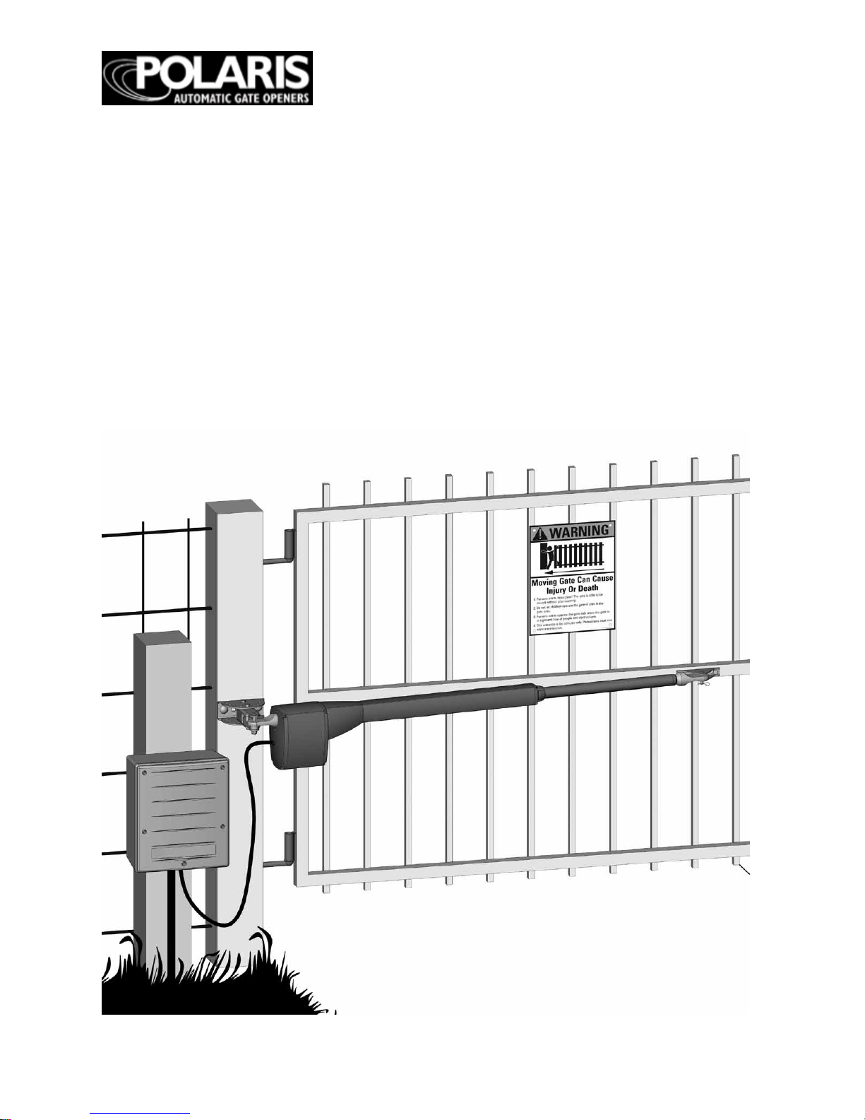
Warning Signs and Labels
Required Safety Precautions for Gates
Warning signs alert people of automatic
gate operation. They are required when
insta lling the Po la ris Automatic Gate
Operator. If pedestrian s will be in the area,
install a walkthrough gate for their use.
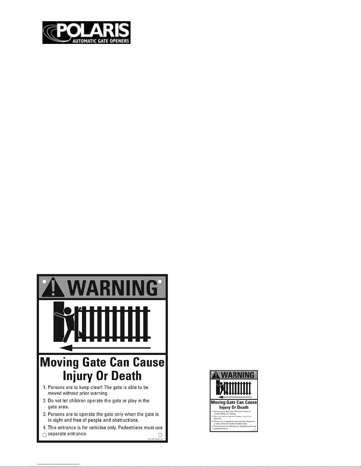
Warning Signs
The warning signs must be installed on
both s i d es o f th e g a te.
These warning signs and decals must be
used. If any
were missing wh en the
gate operator was
purchased,
immediately contact Polaris Automatic
Gate Op erators for replacemen ts.
Figure 2
Warning signs (two enclosed) to be
installed on each side of the gate
(three to fi v e fe et a b ov e th e b otto m
of the g ate )
Figure 3
Install warning decals,
one on each side of gate
operator
Page 8
Page
8
INST A LL ING TH E PO L AR IS 500 & 700 S W ING OPER AT O R
WARNINGS---------------------
1. Read and follow all instructions.
2. NEVER let children
operate the gate or play with the controls.
3. Keep people and objects away from the gate and its immediate areas, both open and closed.
4. After the limit adjustments are made, all auto reversing controls including the current
sensing circuit built into
the Polaris must be checked. They must be working and set to proper
sensitivity. Failure to adjust and retest the gate system increases the chance of injury or
death.
5. T e st th e sy ste m M ONT H L Y. Ch e ck to ma k e su r e that a ll a uto -reversi ng d evices includin g
the current sensing circuit are working and set to the proper sensitivity.
6.Verify that the emergency (manual ) release pin connected to the gate leaf can be easily
removed. This check should only be made with the battery disconnected to prevent the gate
from moving during the test.
7. Thi s is a VEH IL CL E GAT E ONLY. Ped estri an s must use a sepa rate e ntra nc e.
8. NEVER install any control device on the outside of the Polaris cabinet or in such a way that
someone can reach through the gate to activate it.
9. SAV E THE S E IN S TRUC T I ONS!
CAUTIONS-----------------------
1. NEVER operate the gate unless you can see it.
2. Do not enter the gate area while the gate is in motion.
3. Do not allow children near the gate and do not allow anyone to ride on the gate.
4. Do not attempt to drive through the gate opening while the gate is in motion.
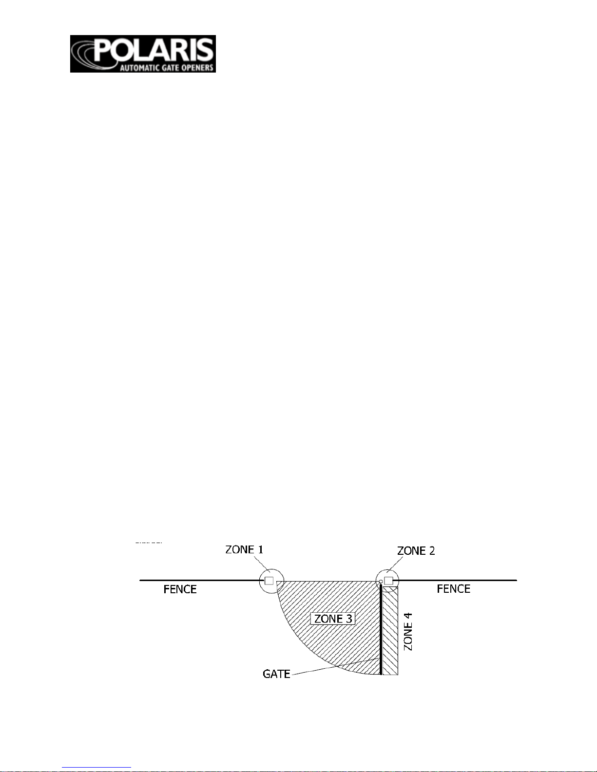
ENTRAPMENT ZONES---------------------
Zone 1- Leading edge of the gate and catch-post
Zone 2
- Area between g ate and hinge post.
Zone 3- The gate path or "arc of the swing"
Zone 4- The area between the gate in its' open position and any obstruction like a fence,
building, landscaping feature, etc...
Zone 5- Not shown below but similar to zone 1- the point where tw o biparting gate leafs meet
when cl osed.
Page 9
Page
9
Page 10

Page
10
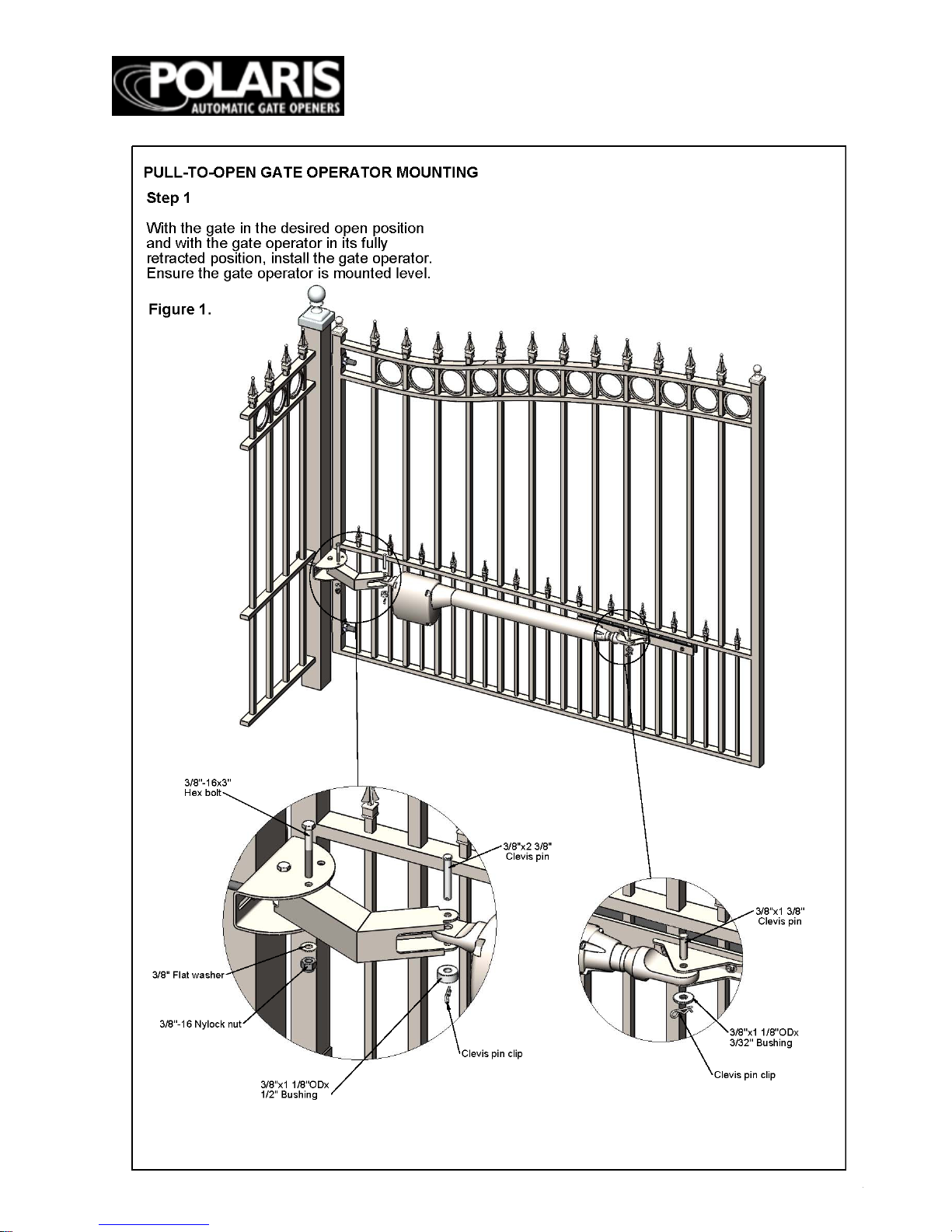
Page 11
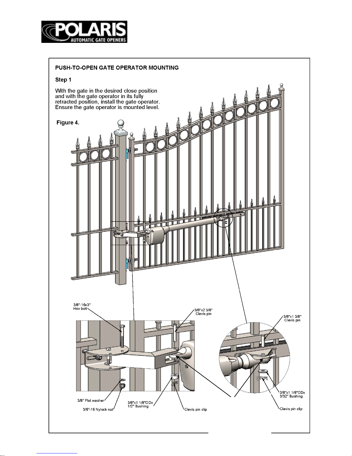
Page
11
Bushings to be set
betw ee n b otto m
side of actuator
rod ends and
mounting bracket
Page 12
Page
12
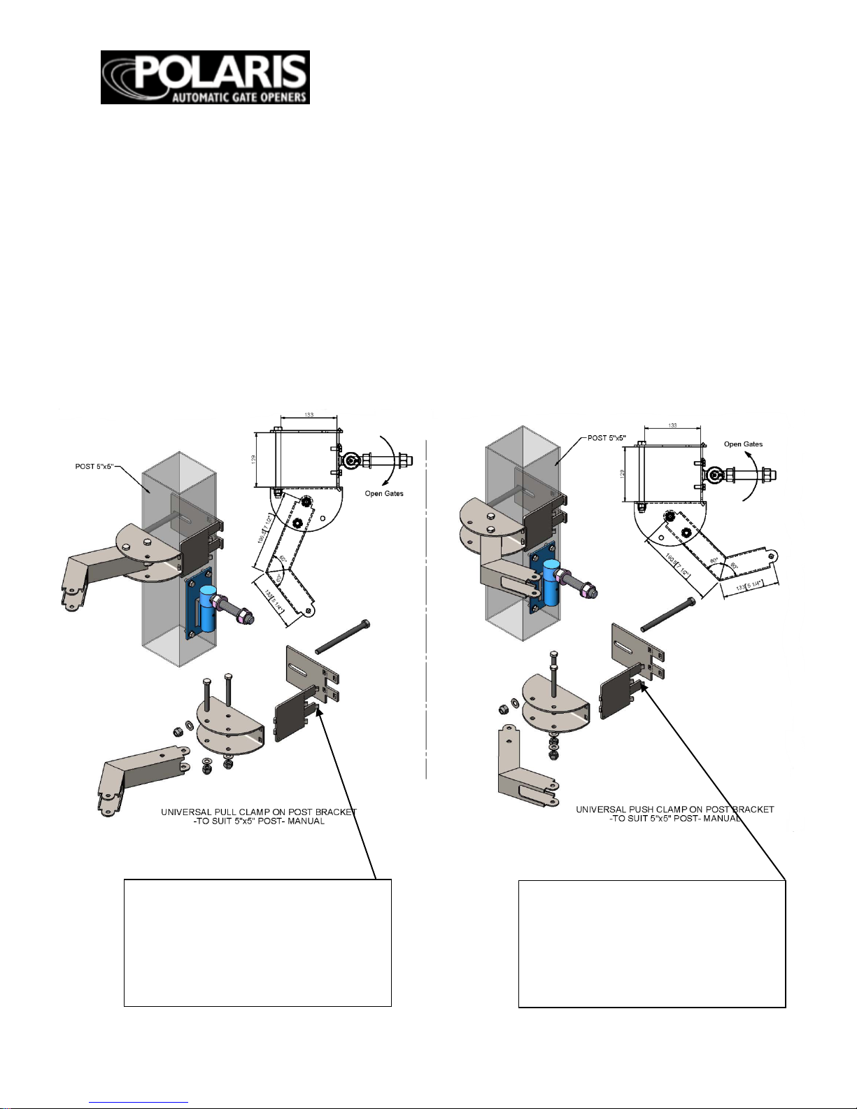
Page 13

Page
13
Amazing Gates Post Mount Brackets Pull and Push
Arm
with Amazing Gates 3 1/2" Pos ts
With the purch ase of a Polaris Opener System, you will receive the Amazing Gates Universal
Pull brackets and gate attach brack et(s).
The Am azin g Gates post attachment arm does not require drilling of the post to be installed.
You simply se t it in to the p osi tion and bolt it tight. The correct angle is preset.
3 1/2" Post Push to Open
3 1/2" Post Pull to Open
“AGA recommends using self
tapping screws on flat plates as
indicated after final setup is
compl ete. This will help to secure
the univ ersal bracket from
shifting”
“AGA recommends using self
tapping screws on flat plates as
indicated after final setup is
compl ete. This will help to secure
the univ ersal bracket from
shifting”
Page 14
Page
14
Amazing Gates Post Mount Brackets Pull and Push Arm
w i th Am a z i n g G ate s 5
" Po st s
With the purchase of a
Polaris Opener System, you will receive the Amazing Gates Universal
Pull brackets and gate attach brack et(s).
The Am azin g Gates post attachment arm does not require drilling of the post to be installed.
You simply se t it in to the p os i ti o n an d bo l t it ti gh t. The correct angle is preset.
5" Post Pull to Open
5" Post Push to Open
“AGA recommends using self
tapping screws on flat plates as
indicated after final setup is
compl ete. This will help to secure
the univ ersal bracket from
shifting”
“AGA recommends using self
tapping screws on flat plates as
indicated after final setup is
compl ete. This will help to secure
the univ ersal bracket from
shifting”
Page 15
Page
15
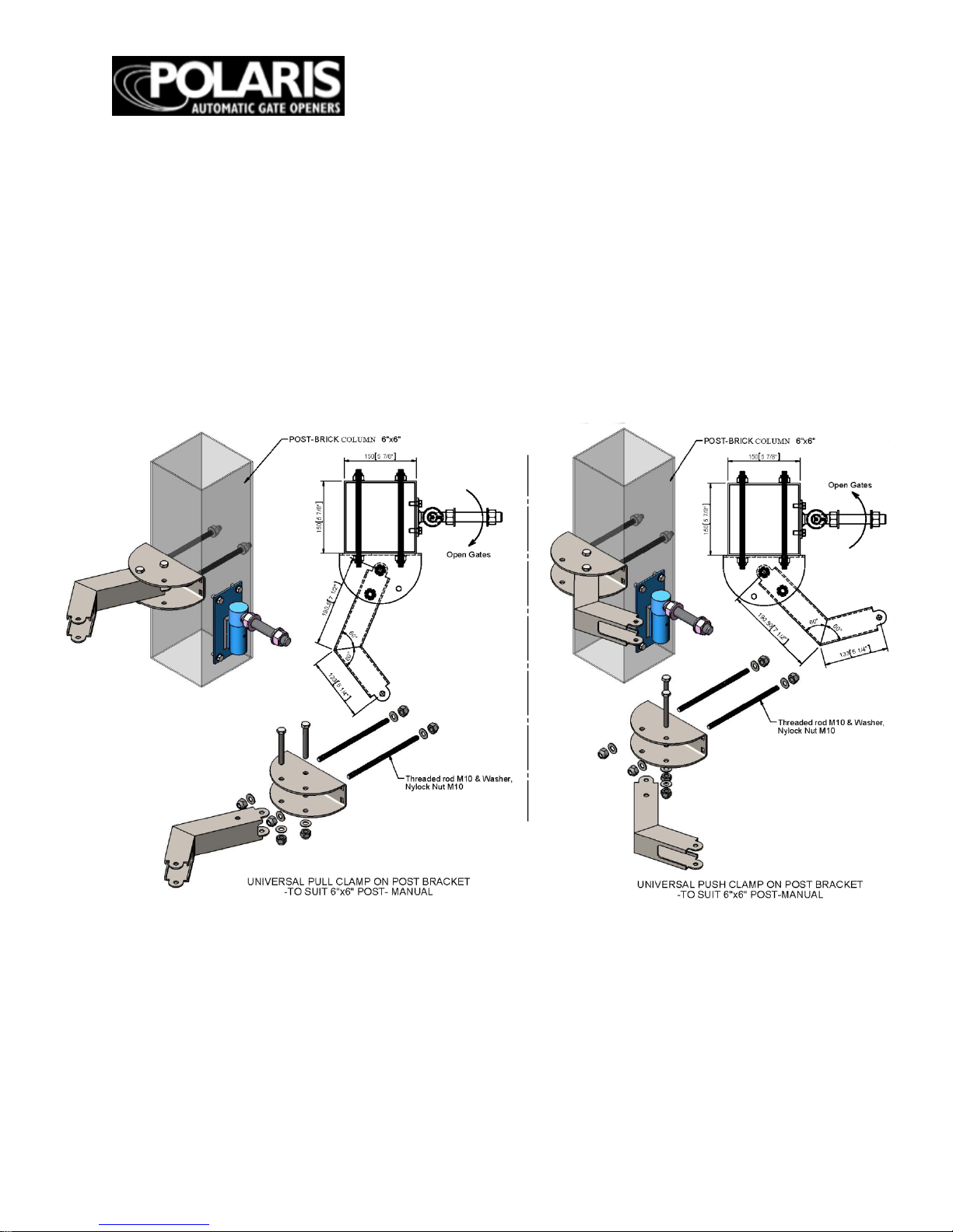
Amazing Gates Post Mount Brackets Pull/Push Arm
with
customers existing Posts other than Am azi ng Ga tes.
With the purch ase of a Polaris Opener System, you will receive the Amazing Gates Universal
Pull and Push brack ets and gate attach bracket(s). These brackets can be used with your
exiting posts or any non-Amazing Gates posts, to include column mounting. Though the
Am azing Gates bracket system can be used on any post/column setup, the diagram shown
below must be followed concerning geometry of pivot point and hinge point.
Page 16

Page
16
Board Layout Description
LED’s
1. 18 VAC Power
2. 24V Converter
3. Gate Operator Retracting
4. Gate Operator Extending
5. Obstruction
6. Auto Cl o se
7. Battery OK
8. Battery Charging
9. S tatu s
10. Safety Loop
11. Shadow Loop
12. Exit Loop
13. Radio Receiv er
Potentiometers
14. Stall Force Adjustm ent
15. A u to Cl o se A d ju stmen ts
Buttons
16. Cycle
– used as an input device
17. S e t Lim it
18. Learn Code
19. Power Save
Fuses
20. 15 amp Fuse
21. 4 amp Fuse
Connectors
22. Buzzer Conn ection
23. RF Board Connection
Page 17

Page
17
DIP S W ITC HES
* - Defau l t fa cto ry se tti n g
Block 1, D IP Switc h 1
– A uto C lose
ON
– Auto close feature enabled
OFF* – Au to c lo se f ea tu re d isa b le
Block 2, D IP Switc h 2 – Pull-to-O pen or Pu sh-toOpen fo r P rimary G a te Operator
ON – Prima r y gate ope rat or set up for push -to-open
operation
OFF* – P r ima ry gat e opera tor s et up for pull-to-open
operation
Block 2, D IP Switc h 3
– Pull-to-Open or Pus h-toOpen fo r Secondar y Ga t e Oper at or
ON –
S econ d ary ga te oper ator se t up for
push-toopen operation
OFF* – S e con d ary gate op era tor set up for pul l
-toopen operation
NOTE : On ly ac t ive if B lo ck 2, DIP S w itc h 1 is s et in
the ON position
Block 2, D IP
Swit c h 4
– T iming of D ua l Gates
ON – One gate is delayed when opening or closing
OFF* – G ates open and close simultaneously
NOTE : On ly ac t ive if B lo ck 2, DIP S w itc h 1 is s et in
the ON position
ON – Exte nde d soft star t/ stop ope r ation en ab led
OFF* – Normal soft sta rt / s to p operation
Block 1, D IP Switc h 4 – Time of Sof t Star t/S t op
ON – Ma x. exten ded t ime of sof t start/ stop op era tio n
OFF* – Ext end ed time of soft star t/st op oper at ion
NOTE : On ly ac t ive if B lo ck 1, DIP 3 is s et to O N
Block 2, D IP Switc h 1 – Single or Du al Gat e
ON – Dual gate applications
OFF* – S in g le ga t e ap p lica t ion s
Block 1, D IP Switc h 2 – Aud ib le Mo t io n Ala r m
ON – Audible motion alarm enabled
OFF* – Au d ib le m ot io n ala r m d isa b led
Block 1, D IP Switc h 3 – Extended Soft Start/Stop
NO T E : To ad ju st au to clo se t ime ref er to f igu r e 17.
Block 2
Block 1
NOTE : A l l DIP
Switches are
shown in the factory
Block 2, D IP Switc h 5 – Sequencing of
Dua l G a t e
Opening and Closing
ON – Secon d ary ga te oper ator op en s
firs t an d c lo se s
second (2 s e cond delay)
OFF* – P rimary gate operator opens
firs t an d c lo se s
second (2 s e cond delay)
NOTE : On ly ac t ive if B lo ck 2, DIP 4 is
in the ON po s itio n
Block 2, D IP Switc h 6 – D ual Gate
Po sit io n Limit
Settings
ON – Set lim it se tt in g for sec o nd ar y
gate operator
OFF* – S e t lim it s e tt in g for prim ar y
gate operator
NOTE : On ly ac t ive if B lo ck 2, DIP
Sw itc h 1 is se t in th e
ON position
Block 2, D IP Switc h 7 – Off - Not Used
Block 2, D IP Switc h 8 – Off - Not Used
Page 18

Page
18
WIRING OPERATOR
NOT E: Be fore po wer ing, gate ope rat or mu st be
connected to the control box
– damage may occur if
gate op era tor is conne ct ed dir ectly to a bat tery or
other power so urce.
Step 1
Ensure the contr ol bo x power s witc h is in the OFF
positio n. T he con tro l box powe r switc h is loca ted on
the bottom of the control box.
NOT E: Us e only 16 gau ge dua l cond uct or, mu ltistranded, direct buria l wire f or AC p ower hookup.
Follow local electrical codes.
Step 2
If usin g AC power t o char ge the b attery, c onnect w ir e
to the control box as shown in fig. 19.
If chargin g bat tery w ith a solar pa ne l(s), refe r to
Accessor y Hoo k
-Up D iagr am fi g. 32 on page 28.
Con ne ct wir e s f rom primary opera to r (and seco ndary
operator if in stallin g on a dua l gate) to the contr o l box
as shown in fi g. 19. Wir e shou ld be bur ied in
ac cor d anc e wit h
local codes.
WARN ING: DO NOT CONN ECT BOT H
TRANS FORM ER AND SO LAR PAN EL. THIS
SYSTEM IS DESIGNED TO RUN ON ONL Y ONE
POWER SOUR C E. C ONNE CTING BOT H POWER
SOURCES
CAN RESULT IN D AMAGE T O CIRCU IT B OARD
AND WILL VOID WAR RANT Y.
Figure 19
Page 19

Page
19
Circui t Board
Step 5
Connect the battery terminal
wi re s to the ba tter y.
Step 6
Plug in transform er. Turn control
box power switch to the ON position.
Step 3
The transformer provided is for dry
location use only. If used in an outside
outlet, the transformer must be enclosed
or covered for weather protection. Attach
AC power wire to the transformer.
NOTE: DO NOT PLUG TRANSFORMER
INTO AC POWER UNTIL ALL WIRING IS
COMPLETED.
Step 4
Install the battery by placing the battery
into the control box. The control box can
accommodate one or two batteries.
Warning:
Do not attempt to splice operator
wires for the purpose of extending your wiring
conn
ections. Doing so can void your warranty.
Contact technical supp ort for recommended
procedure. 1-877-313-8902.
Batte
Second
Battery
(not included)
Figure 22
Black (-)
Red (+) term i n al
WAR N ING : Please make sure
the batteries are fully charged
before connecting and poweri ng
up the new circuit board.
Undercharged batteries m ay
damage the circuit board and
void your warranty.
Page 20

Page
20
WIR IN G THE OPERATO R
LED Descriptions
Prop er wirin g and pe rfor ma n ce can be verif ied b y
chec kin g the opera tio n of the LED’ s loc ated on th e
cir cu it b oa rd.
LED #1: 18VAC OK
Lit wh e n A C po wer is be in g s up plie d t o the c ir c u it
board.
LED #2: +24V OK
Lit whe n 24V con vert er is acti vat ed.
LED #3: IN
There are two “IN” LED’s. One near the Opener 1
terminals and one near the Opener 2 terminals.
On e LED wi ll lig h t wh e n a sing le ga te op e r ator is
retracting. Both LED’s will light when dual gate
operators are retracting.
LED #4: OUT
The re a re t w o “O U T” LED’s. One n ear the Open er 1
terminals and one near the Opener 2 terminals. One
LED
w ill li gh t w hen a sin
gle gate op erat or is
extending. Both LE D’ s wi ll lig ht w h en dua l ga te
operators are extending.
LED #5
: OBSTR
Lit wh e n an o b str uc tio n is sen s ed.
LED #6: TIMER ON
Blinks when auto close feature is enabled and gate is
in op en po sit io n. L it wh en gat e ar m c yc le limit e r is
automatically activated.
LED #7: BATT OK
Lit whe n batter y is OK or “char ged. ”
LED #8: CHARG IN G
Lit when battery is being charged.
LED #9: STATUS
Blin ks to in d ica t e th at the s ys te m is fun ct io n in g
properly. Also used to indicate a user input during
installation.
LED #10: SAFETY LOO P
Lit when the safety loop contact is made.
LED #11: SHADOW LO OP
Lit when shadow loop contact is made.
LED #12: EX IT LO O P
Lit wh e n an e xit lo o p co nt a ct is m a de.
LED #13: RADIO REC VR
Lit wh i le tr a ns m itt er bu t to n is pu sh ed.
Power Sa ve Mo de (Recomm end ed for Solar
Applications)
Polaris Automatic Gate Operators come equipped
with a Po wer S av e f eat ur e. Th e de f au lt mo d e is for a ll
LED’ s to be opera tio na l as descr ibed. If it is desir ed
to con s erve power to maximize battery lif e
Reco mm en ded for th e follow in g step s can be take n.
Pre s s and hold th e P WR S AVE bu tton fo r thre e
seconds. An audible beep will sound confirming the
change to the power save mode. This will disable
sever a l LED’s wh en not a ctivate d fo r five min ute s. In
Po we r Sa ve m od e, th e L ED ’ s wil l op era te a s
descr ib ed upo n an inpu t. Whe n the gate sits idle for
five m in ute s, t he LED ’s w il l t urn off t o conserve
power.
Wh en tr ou b le sh oo t in g th e in sta lla t io n it is
recommended to disable the Power Save feature. The
feature can be disabled by pressing and holding the
PW R SAVE but t on for three secon ds. T w o a udible
beeps will sound confirming the change to normal
mode op era tio n.
Page 21

Page
21
WIRING THE OPERATOR
Page 22

Page
22
PULL-TO-OPEN LIMIT SETTING
(Open gate to inside of property)
Single Gate Installations
Step 1
Make sure the gate is in the fully open position.
Ensure power switch is in the ON position.
Step 2
Verify Block 2, DIP Switch #1 is in OFF position.
Press the cycle button on circuit board and the
gate will begin to close. Stop the gate using the
cycle button when the desired limit has been
reached.
Step 3
Press and hold the “SET LIMIT” button until one
audible beep is heard to acquire the closed limit
setting. The STATUS light will turn on
immediately upon pressing the SET LIMIT
button. The STATUS light will turn off and an
audible beep will verify the closed limit is now
set.
Step 4
Press cycle button on circuit board to return the
gate to the fully open position.
Step 5
Again, using the cycle button close the gate to
verify it meets the desired location. If the gate did
NOT reach the desired closed limit, proceed to
step 6.
Step 6
CLEARING THE CLOSED LIMIT SETTING:
a) Return the gate to the fully open position.
b) Press and hold the SET LIMIT button until two
audible beeps are heard.
c) Two audible beeps will verify the closed limit
setting is now cleared.
Repeat steps 1 – 5 to program the gates “closed
lim it setting”.
WA R N ING: Do not use hand held
transmitters to program primary
and secondary limits. Only the
cycle button should be used until
final set up is complete to avoid
damage to actuators and voiding
warranty.
***Dip switch number 6 dictates which
gate i s b e ing affe cte d b y th e set limit
button, whether setting or clearing the
limit. If dip switch 6 is in the up position,
it will set or clear the limit for the
secondary operator. If it’s in the down
position it will set or clear the limit for
the prim ary operator.***
Page 23

Page
23
PULL-TO-OPEN LIMIT SETTING
Dual Gate Installations
Step 1
Make sure both gates are in the fully open
position.
Ensure power switch is in the ON position.
Step 2
Verify Block 2, DIP Switch #1 is in ON position.
Press the cycle button on the circuit board and the
gates will begin to close. Stop the gates using the
cycle button when the desired limit for the
primary gate has been reached.
Step 3
Veri fy Bl o ck 2, DIP Switch #6 is in the OFF
position. Press and hold the “SET LIMIT” button
until one audible beep is heard to acquire the closed
lim it setting (fig. 28).The STATUS light will turn on
immediately upon pressing the SET LIMIT button.
The STATUS light will turn off and an audible beep
will verify the closed limit is now set.
Step 4
Press the cycle button on circuit board to return
the gates to the fully open position.
Step 5 (setting secondary gate)
Set Block 2, DIP switch #6 to the ON position.
Again, press t
he cycle button. The gates will
begin to close. The primary gate should stop at the
closed limit position that was programmed in the
previous steps. The secondary gate will continue
to close until you press the cycle button on the
circuit board.
Step 6
Press and hold the “SET LIMIT” button until one
audible beep is heard to acquire the closed limit
setting (fig. 28). The STATU S light will turn on
immediately upon pressing the SET LIMIT
button. The STATUS light will turn off and an
audible beep will verify the closed limi t is now
set.
Step 7
Press the cycle button on circuit board to open
both gates. Then once again press the button to
close the gates and verify the closed limits are set
properly. If the gates did not reach the desired
closed limits, proceed to Step 8.
Step 8
CLEARING THE CLOSED LIMIT SETTINGS:
a) Return the gates to the fully open position.
b) Set Block 2, DIP switch #6 to the OFF position.
c) Press and hold the SET LIMIT button until two
audible beeps are heard. Two audible beeps will
verify the closed limit setting is now cleared.
d) Set Block 2, DIP switch #6 to the ON position.
e) Press and hold the SET LIMIT button until two
audible beeps are heard. Two audible beeps will
verify the closed limit setting is now cleared.
Repeat steps 1 – 7 to program the gates “closed
limit setting”.
Page 24

Page
24
PUSH-TO-OPEN LI M I T S ETT IN G
(Open Gate to Outside)
Single Gate Installations
St e p 1
Make sure the gate is in the fully closed position.
Ensure pow
er switch is in the ON position.
St e p 2
Verify Block 2, DIP Switch #1 is in OFF position
and Block 2, DIP switch 2 is in the ON position.
Press the cycle button on circuit board and the
gate will begin to open. Stop the gate using the
cycle button when
the desired limit has been
reached.
St e p 3
Press and hold the “SET LIMIT” button until one
audible beep is heard to acquire the open limit
setting. The STATUS light will turn on
immediately upon pressing the SET LIMIT
button. The STATUS light will turn off and an
audible beep will verify the open limit is n o w s e t.
St e p 4
Press cycle button on circuit board to return the
gate to the fully closed position.
St e p 5
Again, using the cycle button open the gate to
verify it meets the desired location. If the gate did
NOT reach the desired open limit, proceed to step
6.
St e p 6
CLEARING THE OPEN LIMIT SETTING:
a) Return the gate to the fully closed position.
b) Press and hold the SET LIMIT button until two
audible beeps are heard.
c) Two audible beeps will verify the open limit
setting is now clea
red.
Repeat steps 1 – 5 to program the gates
“open limit setting”.
WA R N ING: Do not use hand held
transmitters to program primary
and secondary limits. Only the
cycle button should be used until
final set up is complete to avoid
damage to actuators and voiding
warranty.
***Dip swi tch num ber 6 dictates which
gate is being a ffecte d b y th e set limit
button, whether setting or clearing the
limit. If dip switch 6 is in the up position,
it will set or clear the limit for the
secondary operator. If it’s in the down
position it will set or clear the limit for
the prim ary operator.***
Page 25

Page
25
Dual Gate Installations
Step 1
Make sure both gates are in the fully closed
position.
Verify Block 2, DIP Switch #1,2 & 3 are in the
ON position,
Step 2
Ensure power switch is in the ON position. Press
the cycle button on the circuit boar
d and the gates
will begin to open. Stop the gates using the cycle
button when the desired limit for the primary gate
has been reached.
Step 3
Press and hold the “SET LIMIT” button until you
hear one beep to acquire the open limit setting
(fig. 29). The STATUS light will turn on
immediately upon pressing the SET LIMIT
button. The STATUS light will turn off and an
audible beep will verify the open limit is now set.
Step 4
Press cycle button on circuit board to return the
gates to the fully closed position.
Step 5
Again, press the cycle button on circuit board.
The gates will begin to open. The primary gate
should stop at the open limit position that was
programmed in the previous steps. The secondary
gate will continue to open until you press the
cycle button.
Step 6 (setting secondary gate)
Set Block 2, DIP switch #6 to the ON position.
Press and hold the “SET LIMIT” button until you
hear one beep to acquire the open limit setting
(fig. 29). The STATUS light will turn on
immediately upon pressing the SET LIMIT
button. The STATUS light will turn off and an
audible beep will verify the open limit is now set.
Step 7
Press the cycle button on circuit board to close
both gates. Then once again press the button to
open the gates and verify the open limits are set
properly. If the gates did not reach the desired
open limits, proceed to step 8.
Step 8
CLEARING THE OPEN LIMIT SETTINGS:
a) Return the gates to the fully closed position.
b) Set Block 2, DIP switch #6 to the OFF
position.
Fig.29
c) Press and hold the SET LIMIT button
until two audible beeps are heard. Two
audible beeps will verify the open limit
setting is now cleared.
d) Set Block 2, DIP switch #6 to the ON
position.
e) Press and hold the SET LIMIT
button for until two audible beeps are
heard. Two audible beeps will verify the
open limit setting is now cleared.
Repeat steps 1 – 7 to program the gates
“open limit setting”.
Page 26

Page
26
PRIMARY/SECONDARY GATE
MOVEMENT
For dual gate installations the timing of the
gates opening and closing can be adjusted. To
set a dual gate installation for both gates to
open and close simultaneously, set the DIP
switch es a s follo w s.
Blo c k 2, DI P 1 – O N p osi ti on
Blo c k 2, DI P 4 – O FF position
If it is desired to have one gate open and close
prior to the other, this can be accomplished by
adjus ti n g th e D IP swi tch setting s.
Blo c k 2, DI P 1 – O N p osi ti on
Blo c k 2, DI P 4 – O N p osi ti on
Now d etermine which ga te is desired to open
first and close second. Another DIP swi tch
adjus tment is req u i re d to se t th i s.
For primary g ate operator (wired to operator 1
terminal s) to open first and close second:
Blo c k 2, DI P 5 – O FF position
For secondary gate operator (wired to operator
2 terminals) to open first and close second:
Blo c k 2, DI P 5 – O N p osi ti on
The delay in opening and closing is always set
for two seconds.
PRIMARY/SECONDARY GATE
MOVEMENT
Control Box Cover
Once you have programmed your
remote/keyp ad, you ca n then install the cover
of the control box. Use five #10 x 3/4” screws to
secure the cover to the control box.
Page 27
Page
27
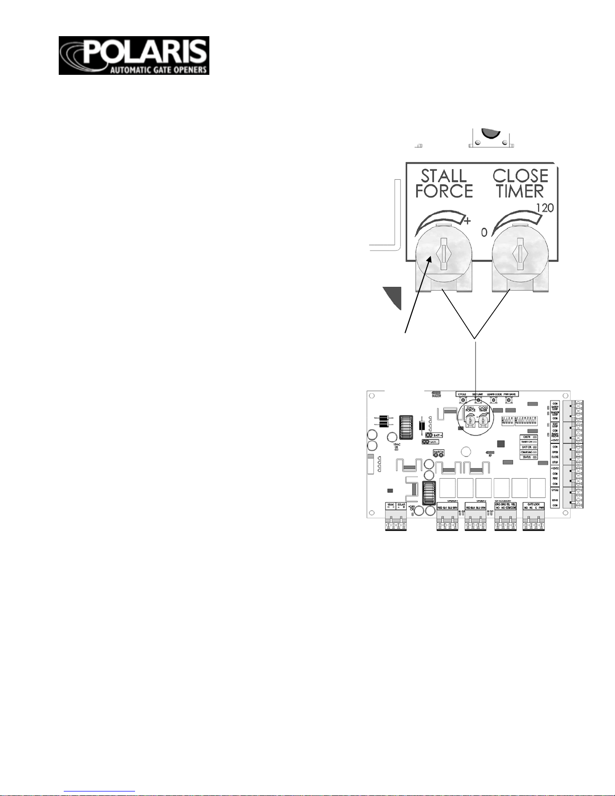
OBSTR UC TION S EN SITI VITY SE T UP
* Note: Cycle is an open/close input.
Exit is a open only input.
IMPOR TA N T : For safety reasons the
obstruction setting or stall force on the Polaris
Autom atic Gate Operator control boa rd comes
from th e fac tor y s et a t minimum , (turned all
the way counter
-clockwise). In many gate
installations, this setting will need to be
adjusted to overcome the w eight and size of the
gates.
The S TA L L FOR CE po ten ti om e ter on th e
circuit board controls the obstruction
sensitivity (or the amount of force the operator
wil l ap p l y to an o bs tru ction ) be fo re it
automatically stops and reverses direction of
the gate. Adjust the sensitivity beginning at the
factory d efa u l t co u n ter -clockwise position.
Continu e to incrementally increase the force
until the gate can open and close without
obstructing under its own weight.
NO TE: Th e stal l fo rc e may need to be
increased in cold weather du e to increased
resistance from gate hinges.
NO TE: Th e O BS T R L ED w il l lig h t to in di ca te
an obstruction is sensed.
NOTE : Th e Stall Force dial in Figure 31
should ideally be at the 10 o’ clock position
inste ad o f th e 12 o’ clock position pictured.
Figure 31
Obstruction
Potentiometer
Page 28

Page
28
Auto Close T im er
The amount of time betw een opening the gate
and automatically closing the gate can be
adjusted between 0 seconds and 120 seconds.
The adjustment is made by
turning the
CLOSE TIMER potentiometer. The default
position of the potentiometer is zero seconds.
Timer wi ll
activ ate after gates have comp leted one full
cycle. To increase the dela y time, turn the
potentiometer
clockwise.
NOTE: Only active if Block 1, DIP switch 1 is
in the ON position.
PO LA R IS STRONG L Y
RECOMMENDS THE USE OF A
SAFETY DEVICE SUCH AS:
PHOTO BEAMS OR SAFETY
LOOP WHEN AUTO CLOSE
TIME R IS ACT IV AT ED !
Page 29

Page
29
TRANSMITTER/RECEIVER
NO TE: Al l Pol ar i s Au to mati c G a te O pe ra to r
transmitters use a standard code set at the
factory. It is recommended that this code is re-set
for safety and security before programm i ng
receiver.
Step 1
Remov e the battery access cover on the
transmitter. When the cover is off, you will see
the battery and the DIP switches.
Step 2
The DIP switch block contains 10 small switches.
Using a small screwdriver or pen, move any
switch or combination of the switches to either the
open or closed position.
NOTE: Do not set the switches to all open or all
closed.
Step 3
Locate the LEARN COD
E button on the circuit
board in the control box.
Step 4
Press and hold the LEARN CODE button for at
least three seconds, but no more than five
seconds. Upon release, the CHARGING LED will
light, the STATUS LED will stop blinking, and an
audible beep will occur verifying the circuit board
is in the learn code mode.
Step 5
Press and hold the transmitter button until the
CHARGING LE D t urn s off, th e STATUS light
blinks, and an audible beep occurs. Release the
transmitter button. The transmitter code is now set.
Step 6
Replace the battery access cover on the transmitter.
Step 7
Verify the transmitter is operational by pressing
the transmitter button. The
RADIO R ECEIVER
LED
will light and the gate will move if the setting is
correct.
If the gate does not move, repeat the process
starting with step 4.
NOTE: The control box circuit board can learn
and hold up to 10 different codes.
NOTE: To clear all codes, press and hold the
LEARN CODE button for 10 seconds. Two audible
beeps verify LEARN C ODE has been cleared.
Figure 25
DIP S wi tch es
Transmitter
Figure 26
Page 30
Page
30
* Note: Some ac c e s s orie s ma y re quire a dditional w ire a nd/or ha rdwa re a nd is to be s upplie d by the
installer.
Page 31

Page
31
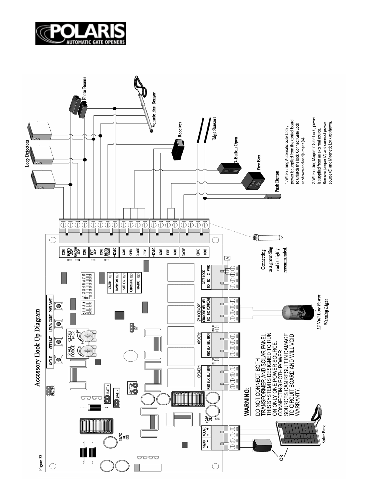
ACCESSORY HOOK UP DIAGRAM
Telephone Entry System
Fire Access Control
Keyswitch Control
Solenoid Lock- #1 see page 30.
Accessory Con nection s Strip
Magnetic Lo ck- #2 see page 30
Please refer to Magnetic
Lock instruction manual for
connection instructions.
Connections differ for 12v or
24v connection.
Page 32

Page
32
ACCESSORY HOOK UP DIAGRAM
Wired K eyp ad
Photo Eye Beams
Victory PB-1200 Photo Eye Beams
External R adio Receiver
Page 33

Page
33
EXIT WAND HOOK UP DIAGRAM
Page 34

Page
34
PHOTO EYE
HOOK UP DIA GRAM
NIR Photo Eye
The NIR photo-eye has two parts: the EMITTER and the REFLECTOR. The
EMITT E R has 5 screw terminal s labeled by color. Attach the terminals in the emitter
to thos e o n th e gate operator circuit board as shown below. Use a direct-burial type of
control wire like "sprinkler wire" and posi tion the emitter on the hinge-side of th e
*Use these instructions in combination with the NIR
instr u cti o n s th at c o m e wi th th e p h oto e ye s. *
NIR Photo
Brown
Gray
White
Black
Blue
*Blac k wire no t used *
Page 35

Page
35
PHOTO EYE HOOK UP DIAGR A M
The IRB 4X photo-eye has two parts: the TRA N S M IT TE R an d th e REC E IVE R. T h e
TRANSMITTER has 2 screw terminals labeled plus and minus. The RECEIVER has 5
terminal s, DO NOT u se terminal #4. To connect the units to the gate operator circuit
board, see the drawin g below. Use a direct-burial type of control wire like "sprinkler
IRB 4X Photo Eye
*Use these instructions in
combination with the IRB 4X
instr u cti o n s th at c o m e wi th th e
Page 36

Page
36
EMERGENCY
DISCONNECT
CAUTION
: The gate will move
freely and uncontrolled when the
gate operator is remov ed from the
gate. ONLY d isconn ect the gate
operator when the con trol box
power switch is OFF an d the gate
is NO T m ovin g .
Page 37

Page
37
TECHN ICA L SP EC IF ICATIONS
Mechanical Specificati ons
Motor: 24 VDC
Shipping Weight:
POLAR IS 500: 6
5 lbs
POLARIS 500/502: 88 lbs
POLAR IS 700: 65
lbs
POLARIS 700/702: 90 lbs
Travel Speed:
16 seconds for 90° (opening
under normal conditions and normal load)
Electrical Specifications
Voltage Ratings:
Powered by a 24 v VDC motor
18 VAC transformer: 18.0 to 22.0 VAC
12 V Battery: 12.0 to 13.5 VDC 7.2Ah
Charging Circuit: 12.0 to 14.8 VDC
Transm itter/R eceiver Frequ ency: 433MHz
Transmitter Range: Up to 1 00 feet (90
meters) *varies greatly dep ending on gate
surroundings
POLARIS 500/502
Capacity
12 feet/200 pounds
Stroke Length
19 inches
Minimum Gate Length
60 inches
POLARIS 700/702
Capacity
14 feet/300 pounds
Stroke Length
24 inches
Minimum Gate Length
72 inches
44.6 inches retracted
68.6 inches extended
39.6 inches retracted
58.6 inches extended
Page 38

Page
38
PARTS LIST AND ILLUSTRATIONS
Page 39

Page
39
PARTS LIST AND ILLUSTRATIONS
Secondary Gate Operator
40 ft. cable
Polaris 502
Polaris 702
Circui t Board
Cabinet Dimensions:
14.5h x 12.5w x 6.5d
Transformer
Battery
Page 40

Page
40
TROUBLE SHOOTIN G
The gate(s) stops or reverses before reaching
the desired position.
1. Verif y the gate fr am e is not encou nte rin g an
obstruction and the gate hinges are not binding.
2. If th e OBS T R L ED is lit , th e sta ll fo rc e m ay b e set
too s en sit iv e. Incr e a se th e sta l l for c e by
turning the STALL FORCE potentiometer clockwise
1/8 turn. O perat e th e gate a ga in to s e e if the prob lem
stil l ex ist s. If th e p ro b lem s ti ll e xist s in cr e a se th e stall
force a gain and re try. If the proble m sti ll exists pro ce e
to step 3.
CA UT IO N: Increa sing the sta ll fo rc e reduc es
obstruction pr o tec tio n.
3. Re s et the op erat or by tur ning t he po w er off for
five sec ond s. Turn th e powe r bac k on and pre ss the
CYCLE bu tto n and allo w the ope rat ors to fully
retract.Try operating the gate again to see if the
prob lem sti ll exists. If the gate sto ps befo re rea ch ing
the desir ed p ositio n , clear and re def ine t he limit
sett in gs as de sc r ib ed e ar lier in th e ma n ua l.
4. Che ck for an y loose or in corr ec t conn ectio ns.
5. If steps 1–4 did no t solve the pr ob lem plea se
call technical support at 1-877-313-8902.
The gate will not operate using the handheld
transmitter.
1. Pr e s s tr ansmit t e r butt on to ve rify L E D on
tran s m itt er il lu minates. If not, replace 9V battery.
2. Obse rve "rad io rec ei ver led" on the co ntr o l
board an d verif y it turns on wh en tra nsm itt er
butto n is pres sed. If so,the tra nsm itt er is workin g
corre ctly refer to troubleshooting section “The
Gate
Wi ll Not Opera te.” If the LED does not illuminate,
proceed to step 3.
3. Ref er to page 22 of manual “Transmitter/Receiver”
and relearn the transmitter code. If the problem still
exists proceed to s t e p 4.
4. Verif y RF Board C on nec tio n.
If con n e ctio n s ar e cor re ct, please call technical
support.
The G a te Will Not Cl o se Au tomaticall y
1. M a ke s ure dip switc h 1, bloc k 1 is in t he on
position.
2. Adjust timer to preferred close time.
3. G ate m u st co mp le te on e f ull c yc le be for e t ime r is
activated.
The ga te (s) w il l n ot o p er a te.
1. Verif y pow er switc h is on.
2. V erif y t he ST ATU S L ED is bl in kin g
approximately once per second. If not, check
battery connections and both 4A and 15A fuses.
3. Verify SAFETY LOOP LED, SHAD O W
LOOP LED and EXIT LOOP LED are not on. If
any of the se are on, try disco nn ec tin g the
corresponding device.
4. If using an AC po wer sou r ce, ver ify the 18V AC
LED is on.
5. Verif y the 12V ba tter y volta ge. If belo w 12.3 V,
then replace or recharge the battery.
6. Clear and redefine limits as described earlier in
the manual.
7. Try the CY CL E butto n on the con tro l board.
8. Verify all connections especially the actuators.
9. Verify FIR E BOX, PHOT O BEAMS, or EXIT
WAND (if insta lled) is not pr eve nting ga te
movement.
The gate(s) are operating slowly.
1. This is usually due to low power. Check voltage
on batterie s. If voltage is belo w 12.3 V , a l low time
for b at t er ie s to ch arge b efore o pera t ing gates. (if
this is a so lar app lic a tio n and t here has bee n a lack
of sunligh t, yo u will nee d to char ge batt eries with
a trickle cha r ger befor e op era ting your ga te( s).)
The status light is flashing rapidly.
1. Th is is a lso m o st lik e ly du e to a po we r pro b le m.
Chec k batt ery vo ltage a nd char ge bat ter ies if
necessary.
2. Af t er b atteries ar e f ully charge d, pow e r dow n
syste m for 5 seco nds and tu rn bac k to on positio n.
There are no remaining inputs for 12vdc for my
accessories.
1. You ma y creat e a pigtai l conne ctio n and
con ne c t mor e th an on e a cce ss ory to a 12 vdc inp ut
connector.
Can I a d jus t th e actuator manua lly to fi t my
gate?
1. No. T he act u ato r mu s t be in st a lled in th e fully
retra cted po sitio n and co nne ct ed to the gate att ach
bracket at that p oint. P lease refer to page 1 0 for a
pull-to-open app licat ion or pa ge 12 for a pu sh-toopen application.
Page 41

Page
41
TROUBLE SHOO
TING
MAINTENANCE
Th e 1 5 amp f u s e i s bl ow n.
1. Che ck w irin g from ac tuator ar ms to circuit
board for lo o se or cut conn ect ion s.
2. V erif y t hat a ll w irin g is cor r ec t acc or d in g to
page 18.
3. Chec k for any over he atin g or singed w ir ing.
4. Call technical s upport at 1-877-313-8902 before
attem ptin g to rep lace fu se so as to preve nt an y
further da m age
.
Th e 4 amp f u s e i s bl o wn.
1. Che ck wiring f rom tr a nsfor mer to circ uit board.
2. Chec k for any loos e or incorr ec t conn ectio n s.
3. Che ck ba tt e ry connection s f or any c orros io n or
loo s e wir e s.
4. After re plac ing fus e, ver ify that 18 vac ligh t is
illu min a t ed . (th is is no t val id o n a sola r p ow e red
system.)
5. Ca ll te ch nic a l su pp or t if fuse b lo w s aga in .
How do I reset the limits on my gate(s)?
1. Make sur e you star t with bo th arms in the fully
retracte d posit ion.
2. Cle a r t he limits on both a rms by pressing the se t
lim it bu tt on a nd ho ld ing it in un t il it b eep s t wic e.
Set d ip sw it c h 6 in th e op po sit e po sit ion a nd pre ss
set limit a ga in u nt i l it be eps t wic e . Yo u ha ve n o w
cleared th e limits for bot h op er a to rs.
3. Dip switc h num b er 6 dictate s which ga te is
being af fec ted by the se t limit but ton, whet her
sett in g or cle ar in g th e lim it. If dip sw it c h 6 is in
the up po s itio n, it will s et o r cle ar t he limit for t he
secon da ry ope rat or. If it’s in the dow n posit ion it
will set o r clear t he limit for t he primar y oper ato r.
4. Once limits have been cleared, cycle the gates
to (clo s e- p ull to open) o r (open- push to open)
and stop th e gates u sing th e cycle bu tton w hen a
gate gets to the desired closed/open position. Once
this oc cur s s et the l im it f or th a t ga te by pr e ss ing
the s et limit b utt o n un ti l it be ep s on ce. (m ak e su re
dip s wit c h 6 is set a pp ro pr ia t ely ) C yc le th e gates
back to the open/ closed position.
5. With the gat es in the ope n/c lose d po sition,
cycle gates to close/open once again. This time
stop the ga te s when the othe r gate get s to the
des ir ed s to p lo ca tio n. On ce th a t is ac co mp l ish e d,
set th e limit f o r th at gate by setting the dip switch
6 cor re ct ly an d pr e ss in g th e set limit b ut t on un t il it
beeps once.
Preventive Maintenance
• Using a clean, dry cloth, wipe the gate
operator shaft, and then apply a silicone
spray. The silicone spray will reduce friction
in extreme temperature ranges and help the
gate operator operate smoothly. This should
be repeated every 4–6 weeks. If needed, spray
a small amount of silicone lubricant into tiny
pinhole found on shaft of actuator with
actuator in extended position.
• Check the gate hinges to make sure gate is
swinging smoothly and freely. Grease hinges
if needed.
• Check batteries occasionally for corrosion
and clean leads if necessary. Check voltage
occasionally.
• In some cold weather climates it is
recommen ded to purchase battery heaters to
ensure that your batteries maintain a charge
throughout cold weather months. In this case,
battery heaters need to be unplugged during
spring, summer and fall months to prevent
overheating.
• For optimal performance, it’s recommended
that new batteries be installed annually.
Customer Service
8:00am to 5:00pm, Mountain Time
Monday – Friday
Polaris Gate Operators
8617 Paseo Alameda NE
Albuquerque, NM 87113
Phone: 877-313-8902
Fax: 800-830-3952
emai l : techsuppo r t@ a m azingga tes.c om
Page 42

Page
42
LIST OF ACCESSORIES
Solar Powered Battery Charger (20-Watt: RSP2 0 ) The solar panel charges
the 12 volt battery when AC power is not available.
One-Bu tto n T ra n sm i tte r. T he transmitter works as an input device allowing
the user to open or close the gate from a remote location. It has a range up to
100 fe et.
Two-Bu tto n T ra n smitte r. The two -button transmitter provides the capability
to remotely opera te two separate devices such as two gates, or a gate and a
garage door opener. It has a range up to 1
00 feet.
Mini-transmitter. The mini-tran smi tter fi ts o n a k eychain and allows the user
to open or close the gate from a remote location. It has a range up to 100 fee t.
Keypad. The keypad allows for entry by authorized guests informed of the
pre-set code. Entering the correct code causes the gate to open or close. T h e
access code can be easily modified.
Pin Lock. The pin lock replaces the clevis pin when mounting the gate
operator to the brackets. It helps to prevent theft of the gate operator from the
gate, while allowing quick release of the operator.
In-Ground Vehicle Sensor . The vehicle sensor is buried near the gate and
senses a veh i cl e that pa sses w i thin its 12-foot range. Once detected, the gate
opens automatically.
Solenoid Gate Lock. The automatic gate lock provides an additional level of
security for the property. W hen the gate swings shut, the gate lock closes,
securing the gate in the closed position. The gate lock is powered from the
control box of the gate operator. The locking mechanism is a mechanical latch.
Magnetic Gate Lock. The automatic gate lock provides an additional level of
security for the property. When the gate swings shut, the gate lock closes,
securing the gate in the closed position. The gate lock is powered from an
external AC pow er source. The lockin g mechanism i s magnetic.
Page 43

Page
43
WARRANTY
You may obt ain additional copies of this manual from our web
site at www.polarisgate.co m, or contact Polaris Gate Operators
at: 8617 Paseo Alameda NE Albuquerqu e NM 87113,
877-313-8902.
Two Year Limi ted W arranty
Limited Warranty Coverage
If your Polaris Gate Operator (sometimes also referred to as
the “Product”) does not work properly because of a defect in
materials or workman ship, Polaris Gate Operators will, for the
length of the period indicated below, which starts with the date
of the original purchase by the first non-consumer purchaser
(the “Limited Warranty period”), at its option either (a) repair
your Product with new or refurbished parts, or (b) replace it
with a new or a refurbished Product. The decision to repair or
replace will be made by Polaris Gate Operators.
Parts Labor Labor
Two (2) Years Two (2) Years
During the “Labor” Limited Warranty period there will be no
charge for labor. (Note: labor appl ies only to the repair of the
Product at an Authorized Repair Center. It does not apply to
removal or installation of the Product any purchaser’s
premises). During the “Parts” Limited Warranty period, there
will be no charge for parts.
You must ship your Polaris Gate Operator to Polaris Gate
Operators during the applicable Limited Warranty period. This
Limited Warrant y excludes both parts and labor for batter ies,
antennas, and cosmetic parts (such as the Product housing).
This Limited Warrant y only applies to Product s purchased in
the United States. This Limited Warranty is extended onl
y to
the original non-consumer pu rchaser (“you” o r “your”) o f a
new Product that was not sold “as is”.
Limited Warranty Service
For assistance in the continental U.S.A. in obtaining the
benefit of the Limited Warranty please carefully follow these
steps:
1) Complete carefull y all troubleshoot ing procedures in the
Maintenance and Troubleshooting Guide in this Manual.
2) If you ar e
still unable to sol ve the problem, contact Polaris
Gate technical support at techsupport@amaz inggates.com.
Please have the mod el and serial number of the Product
available to give to the customer service representative. The
custo me r ser vic e rep re sen t ati ve will provide further assistance
or authorize repair or replacement, as app ropriate.
3) If repair or replacement is appropriate you will be given a
return authorization number (RMA# ). This RMA# must be
visible on all documents and packages returned to Polaris Gate
Operators.
4) Carefully pack the de fective Product o r Product part in a
sturdy shipping carton, include (i) a letter detailing the
complaint, (ii) a daytime phon e number where you can be
reached, (iii) your name and address for any return, (iv) your
sales receipt/proof of purchase, and ( v) the RMA# o n all
correspondence and th e shipping carton.
5) Prepay the freight and insure the d efective Product or
Product part against shipping damage. Note that defective
Products or Product parts shipped freight collect will not
be accepted.
6) Ship the carton to: Polaris Gate Operators, 8617 Paseo
Alameda NE, Albuquerque, NM 87113.
IF REPAIR OR REPLACEMENT IS NEEDED
DURIN G THE LIMITED WARRAN TY PERIOD,
YOU WILL BE REQUIRED TO FURNISH A SALES
RECEIPT/PROOF OF PURCHASE INDICATING
DATE OF PURC HAS E, AMOU NT PAID AND
PLACE OF PURCHASE. YOU WILL BE
CHARGED FOR THE REPAIR OF ANY PR ODU C T
OR PRODUCT PART RECEIVED WITHOUT
SUCH PROOF OF PURCHASE OR FOR REPAIRS
REQUESTED AFTER THE APPLICABLE
LIMITED WAR RANTY PER IOD.
Limited Warranty Limitations and Exclusions
This Limited Warranty ONLY COVERS failures due to
de f ects in materials or workmanship, and DOES NOT
COVER no rmal wear and tear or cosmetic damage. The
Limited Warranty ALSO DOES NOT COVE R dama ges
which occurred in shipment, or failures which are caused
by products not supplied by Polaris Gate Operators, or
failures which result fro m accidents, misuse, abuse,
neglect, mishandling, misapplication, mod ifications or
alterations, faulty installation, connection to an improper
po wer sou rc e, s et-up ad justments, mis-adjustment of
controls, improper maintenanc e, power line surges,
damage from acts of God such as lightning, wind, fire,
flood or insects, introduction of sand, humidity or liquids,
commercial or rental use or service by anyone other than
an Authorized Repair Center.
THERE ARE NO EXPRESS WARRANTIES
EXCEP T AS STATED UNDER “LIMITED
WARR AN TY CO VERAGE ”. POLAR IS GATE
OPERATORS IS NOT LIABLE FOR INCIDENTAL
OR CONSEQUENTIAL DAMAGES RESULTING
FR OM T HE U S E OF T H E PR ODUCT, O R
ARISING OUT OF ANY BREACH OF THIS
LIMITED WAR RANTY. (As examples, this e xcludes
damages for lost time, lost calls or messages, cost of
having someone remove or re-install an installed Product
or Product part, travel to and from an Authorized Repair
Center, etc. The example s listed are not an exhaustive or
exclusive list, but are for illustration only). ALL
EXPRE SS AND IMPL IED W ARRAN TIE S,
INCLUDING ANY IMPLIED WARRANTIES OF
MERCHANTABILITY OR FITNESS FOR A
PARTICULAR PURPOSE, ARE LIMITED TO THE
PERIOD OF T HE LIMITE D WARR AN TY.
Some States do not allo w the exclusion or limitation of
incidental or consequential damages, so the above
limitation or exclusion may not apply to you.
Some States do not allo w limitations on how long an
implied warranty lasts, so the abo ve limitation may not
apply to you.
This warranty gives you specific legal rights, and you
may also ha ve other rights which vary from St ate to State.
PARTS AND SE RVICE S WH ICH ARE N OT
EXPRESSLY COVERED BY THIS LIMITED
WARRANTY ARE YOUR RESPONSIBILITY
.
 Loading...