

Page 1

Page 2
Page 3

Page 4

Copyright 2004 Polaris Sales Inc. All information contained within this publication is
based on the latest product information at the time of publication. Due to constant
improvements in the design and quality of production components, some minor
discrepancies may result between the actual vehicle and the information presented in this
publication. Depictions and/or procedures in this publication are intended for reference
use only. Manufacturer accepts no liability for omissions or inaccuracies. Any reprinting
or reuse of the depictions and/or procedures contained within, whether whole or in part,
is expressly prohibited.
Printed in U.S.A.
2005 Trail Boss 330 Quadricycle Owner’s Manual P/N 9919822
2
Page 5

TABLE OF CONTENTS
VEHICLE IDENTIFICATION NUMBERS 5...............
SAFETY 6..........................................
FEATURES AND CONTROLS 40......................
OPERATION 55.....................................
EMISSION CONTROL SYSTEMS 60...................
MAINTENANCE AND LUBRICATION 61................
POLARIS PRODUCTS 103............................
TROUBLESHOOTING 104............................
SPECIFICATIONS 108................................
WARRANTY 111.....................................
MAINTENANCE RECORD 113........................
INDEX 116..........................................
3
Page 6

4
Page 7
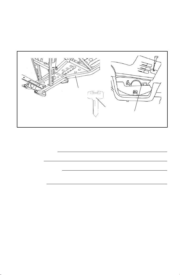
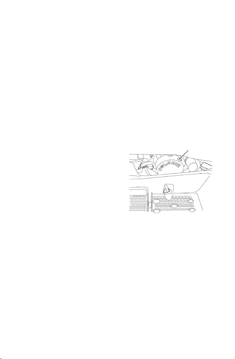
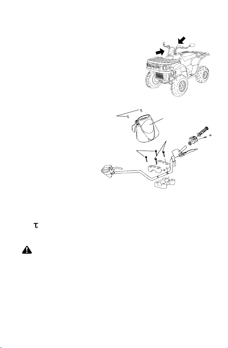
VEHICLE IDENTIFICATION NUMBERS
Record your vehicle’s identification numbers and key number.
Remove the spare key and store it in a safe place. Your key can be
duplicated only by mating a Polaris key blank with one of your
existing keys, so if both keys are lost, the ignition switch must be
replaced.
1
31XX
3
2
Vehicle Model Number:
Frame VIN (1):
Engine Serial Number (2):
(right front side of engine crankcase)
Key Number (3):
5
Page 8

SAFETY
Operator Safety
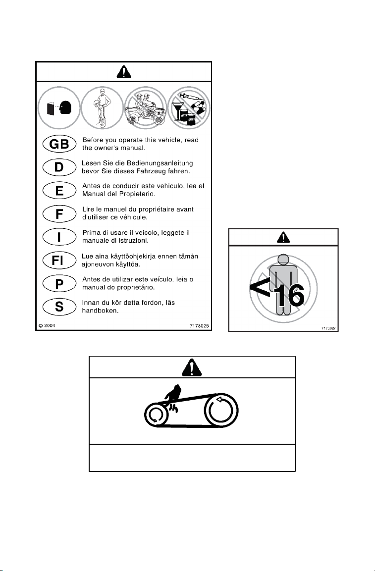
The following signal words and symbols appear throughout this
manual and on your vehicle. Become familiar with their meanings
before reading the manual.
The safety alert symbol, on your vehicle or in this manual, alerts
you to the potential for personal injury.
WARNING
The safety alert warning indicates a potential hazard that may
result in serious injury or death.
CAUTION
The safety alert caution indicates a potential hazard that may
result in minor personal injury or damage to the vehicle.
CAUTION
A caution indicates a situation that may result in damage to the
vehicle.
NOTE:
A note will alert you to important information or instructions.
6
Page 9

SAFETY
Operator Safety
WARNING
Failure to follow the warnings in this manual can result in serious
injury or death.
A Polaris Quadricycle is not a toy and can be hazardous to
operate. A collision or rollover can occur quickly, even during
routine maneuvers, if you fail to take proper precautions.
Read and understand your owner’s manual and all warnings
before operating a Polaris Quadricycle.
Safety Training
When you purchased your new Quadricycle, your dealer offered a
hands-on safety training course. You were also provided with printed
materials that explain safe operating procedures. Review this
information on a regular basis.
If you purchased a used Polaris Quadricycle from a party other than a
Polaris dealer, please request free safety training from any authorized
Polaris dealer.
Age Restriction
This vehicle is an ADULT VEHICLE ONLY. Operation is prohibited
for anyone under 16 years of age.
7
Page 10

SAFETY
Operator Safety
Know Your Vehicle and Riding Area
You are responsible for your personal safety, the s afety of others and
the protection of the environment. Read and understand your owner’s
manual. It includes important information about Quadricycle safety.
Ride responsibly. Know all laws and regulations concerning the
operation of this vehicle in your area.
Restrictions
This vehicle is approved for OFF-ROAD TOWING ONLY. Operating
a Quadricycle/trailer combination on public roads is prohibited.
Equipment Modifications
The warranty on your Polaris Quadricycle may be terminated if any
equipment has been added, or if any modifications have been made,
that increase speed or power.
NOTE: The addition of certain accessories, including (but not limited
8
to) mowers, blades, tires, sprayers and large racks may
change vehicle handling. Use only Polaris-approved
accessories. Know their function and effect on the vehicle.
Page 11
SAFETY
Operator Safety
WARNING
Serious injury or death can result if you do not follow the
instructions and procedures listed here and throughout this
manual.
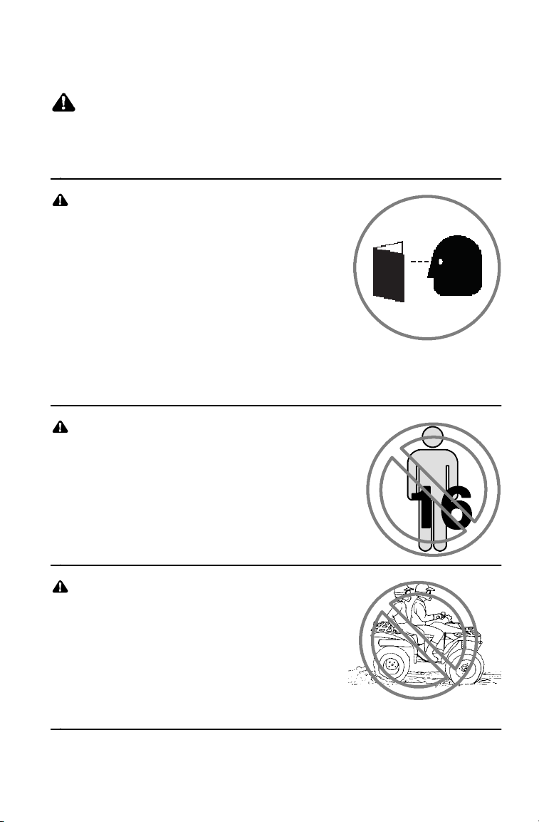
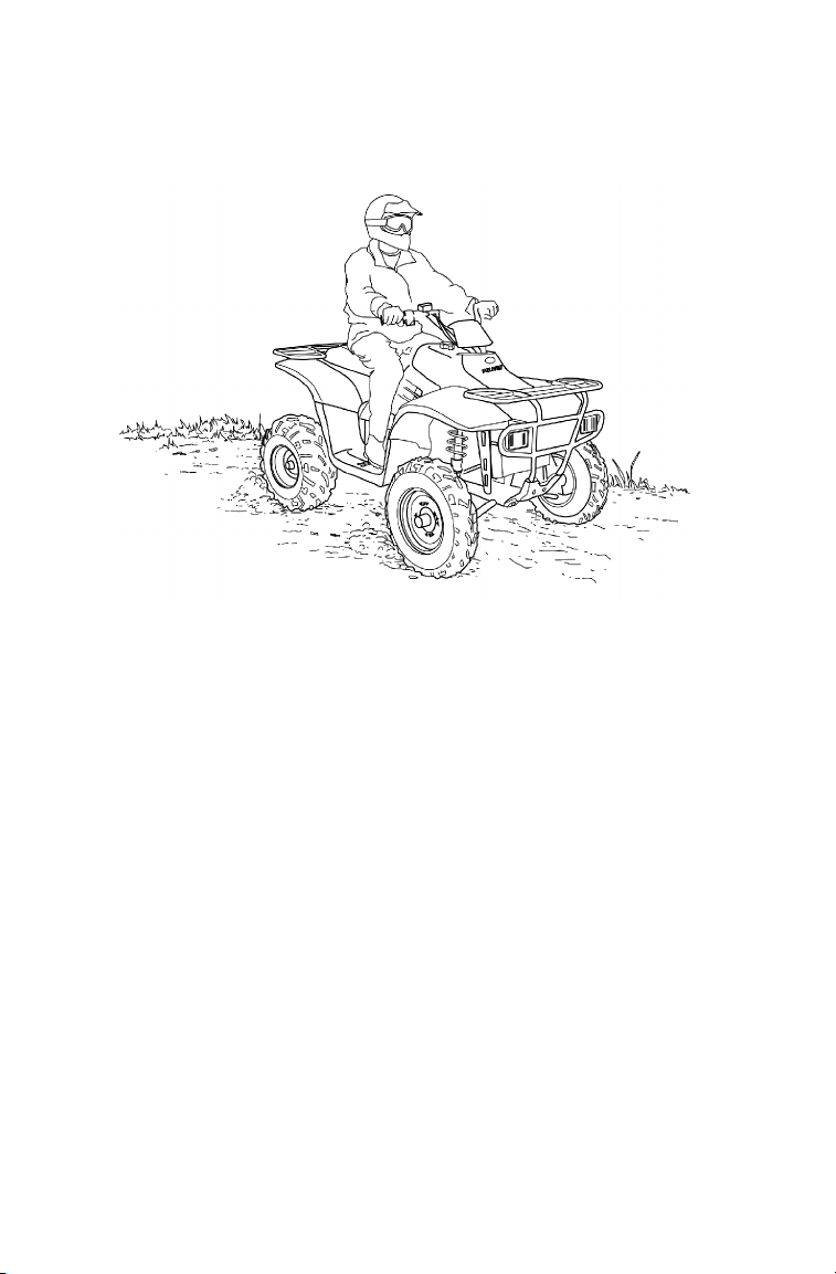
Read and understand all warnings,
cautions and operating procedures
in this manual and on the safety
labels before operating the Quadricycle.
Never operate a Quadricycle without
proper instruction. Take a training
course. Beginners should receive
training from a certified instructor.
Contact an authorized Polaris Quadricycle
dealer or call Polaris at 1-800-342-3764.
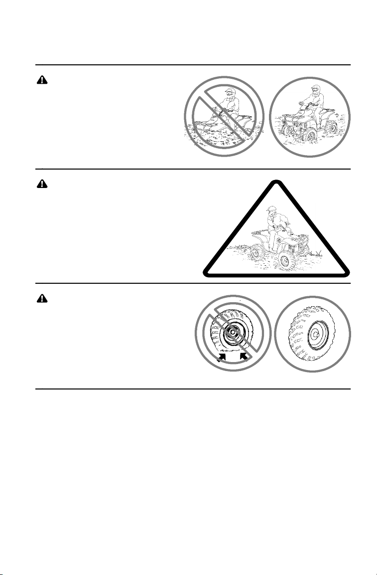
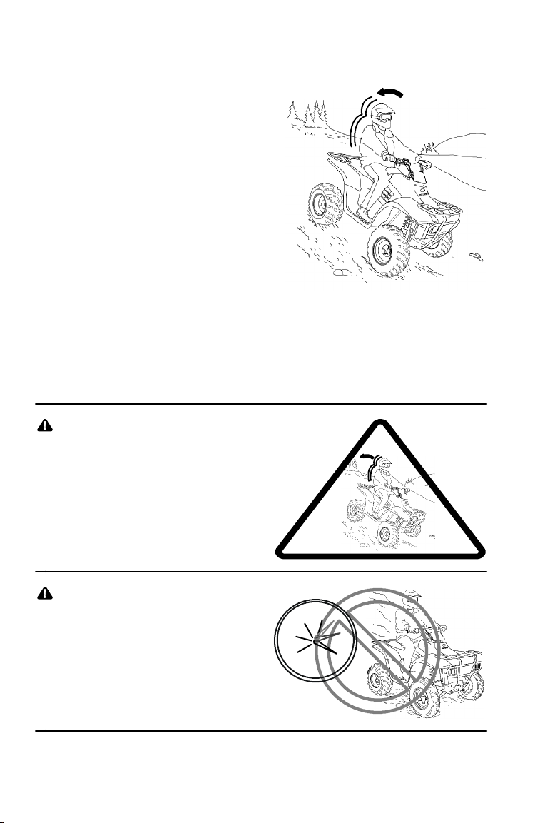
Never permit others to operate the Quadricycle unless they have
read and understand this manual and all product labels, and have
completed a certified safety training course.
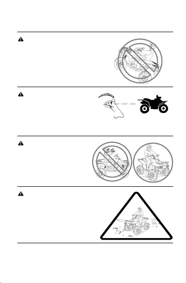
Never allow anyone under 16 years
of age to operate this vehicle.
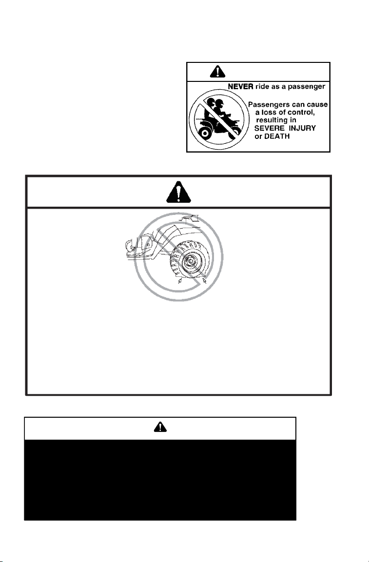
Never carry a passenger. The
purpose of the long seat is to allow
the operator to shift position.
<
9
Page 12
SAFETY
Operator Safety
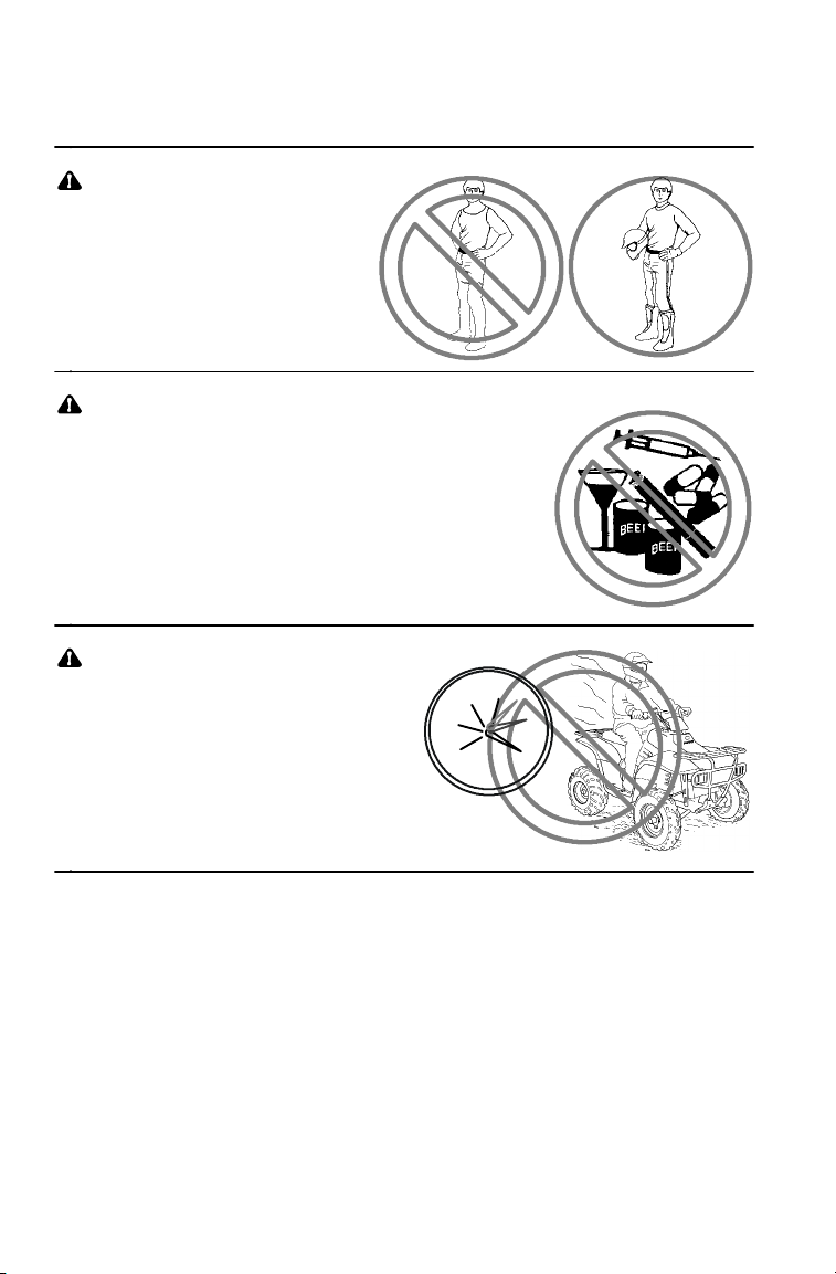
Always wear an approved
helmet that fits properly.
Wear eye protection
(goggles or face shield),
gloves, boots, long
sleeves and long pants.
Never consume alcohol or
drugs before or while
operating a Quadricycle.
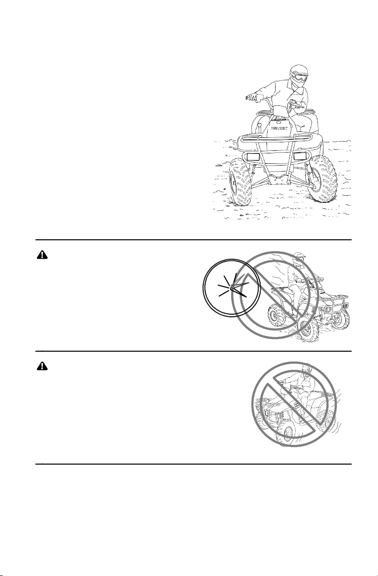
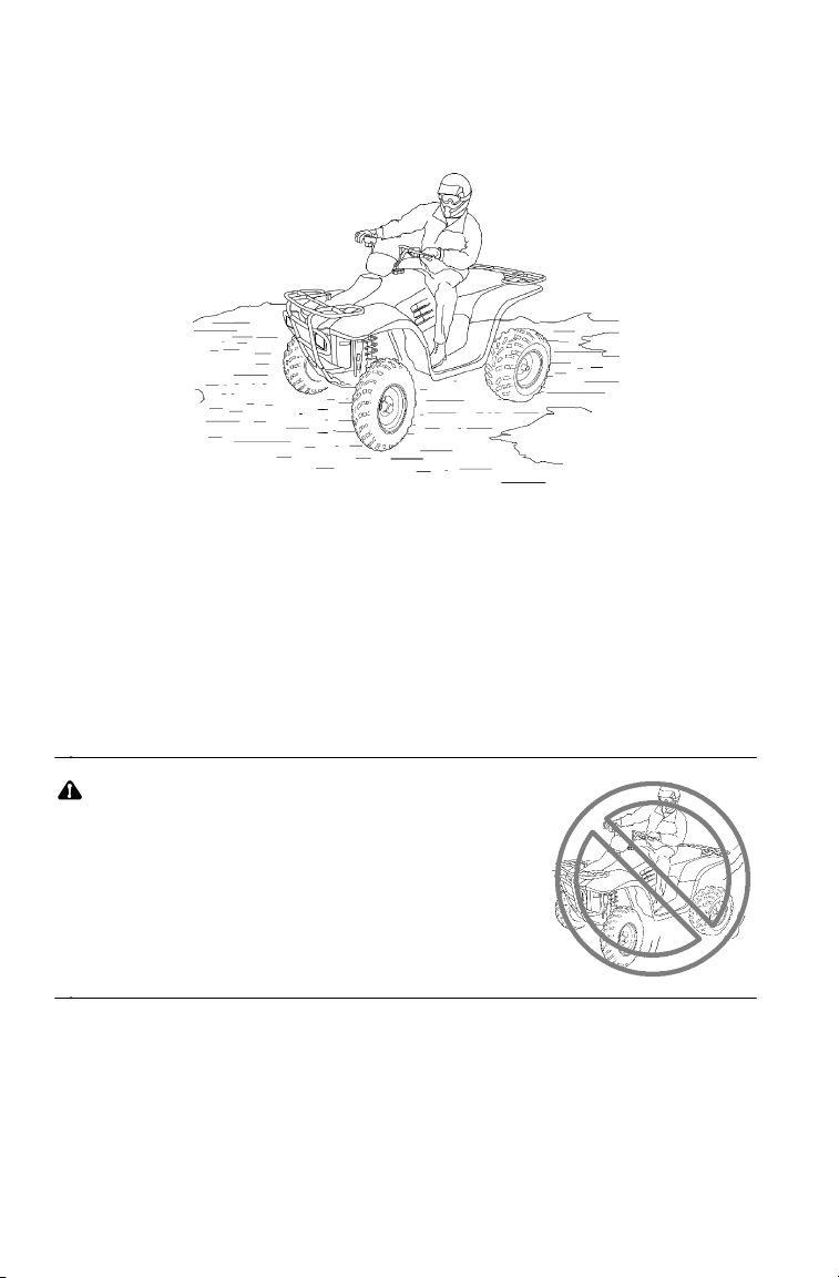
Never operate at
excessive speeds. Travel
and turn at speeds
appropriate for the terrain,
visibility, operating
conditions and your
experience.
10
30
20
40
0
50
10
Page 13
Operator Safety
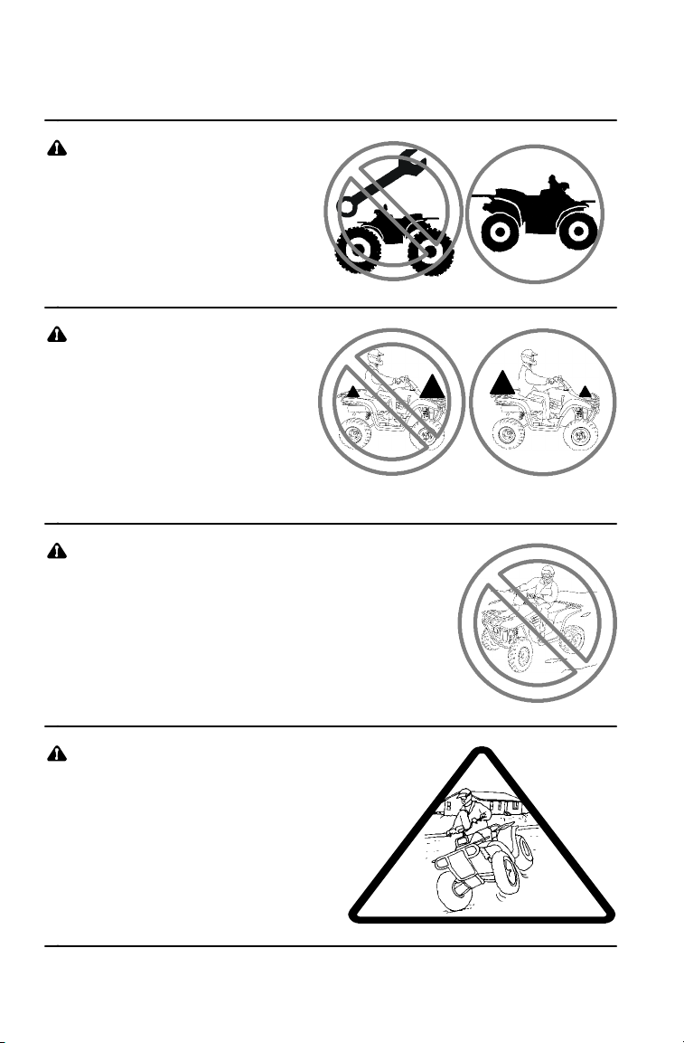
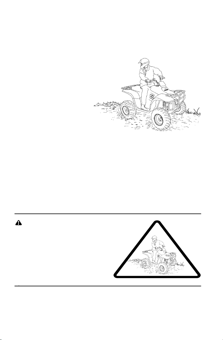
Never attempt wheelies, jumps or
other stunts.
Always inspect your
Quadricycle before each
use to verify that it’s in
safe operating condition.
Follow the inspection and
maintenance procedures
outlined in this manual. See
page 56.
Keep both hands on
the handlebars. Keep
your feet on the
footrests.
SAFETY
Always travel slowly when
operating on unfamiliar
terrain. Use extra caution.
11
Page 14
SAFETY
Operator Safety
Use caution when operating
on rough, slippery or loose
terrain.
Always follow the procedures
outlined in this manual for
turning. See page 25.
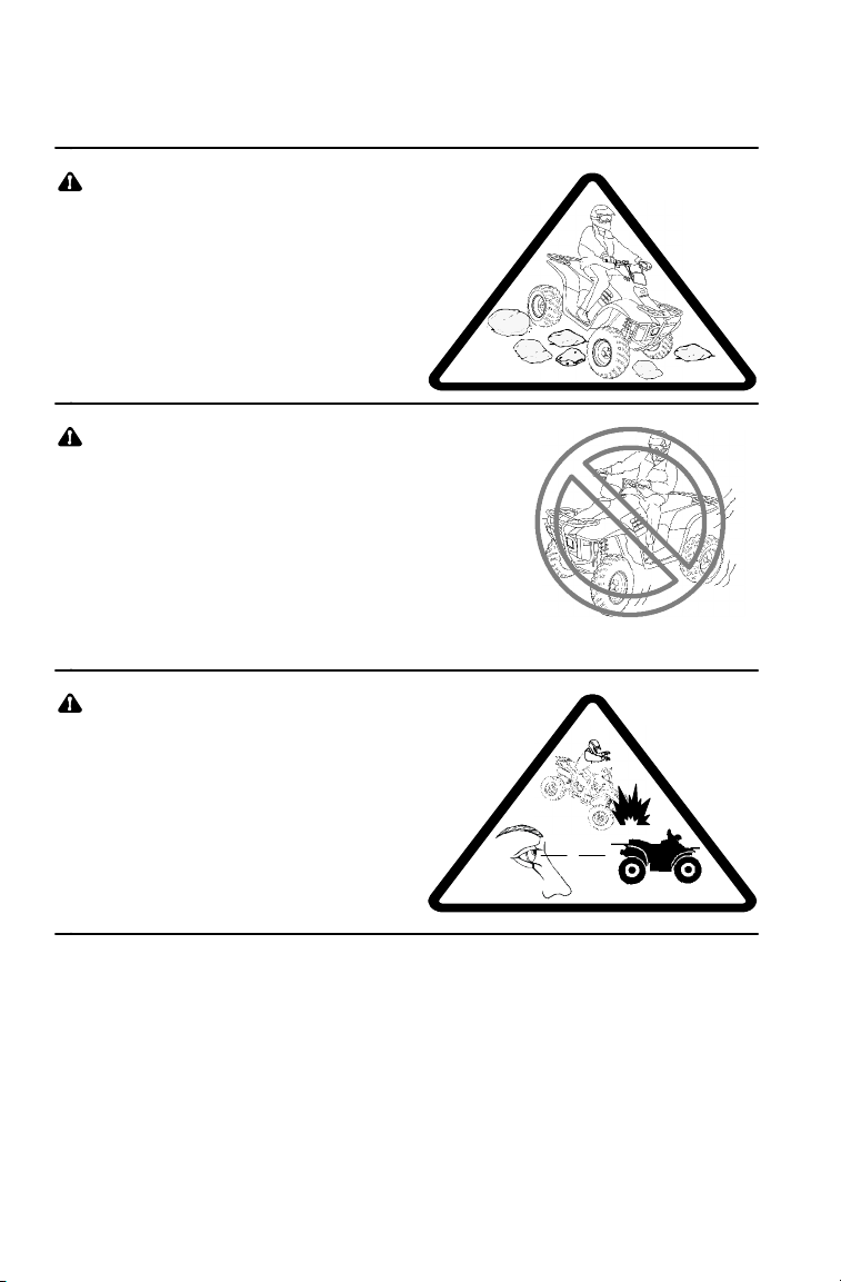
Never turn sharply at
excessive speeds, which can
lead to vehicle overturn.
If a Quadricycle has been
involved in an accident, always
have an authorized Polaris
dealer inspect the entire vehicle
for possible damage, including
(but not limited to) brake,
throttle and steering systems.
12
Page 15
Operator Safety
Never operate on hills too
steep for the Quadricycle or for
your abilities. Practice on
smaller hills before attempting
larger hills. Avoid climbing hills
steeper than 25_.
Always follow the procedures
outlined in this manual for
climbing hills. See page 30.
Always follow the procedures
outlined in this manual for driving
downhill and for braking on
hills. See page 28.
Always follow the procedures
outlined in this manual for crossing
the side of a hill. See page 29.
Never attempt to turn the Quadricycle
around on any hill until you’ve
mastered (on level ground) the
turning technique outlined in this
manual.
SAFETY
>25_
13
Page 16
SAFETY
Operator Safety
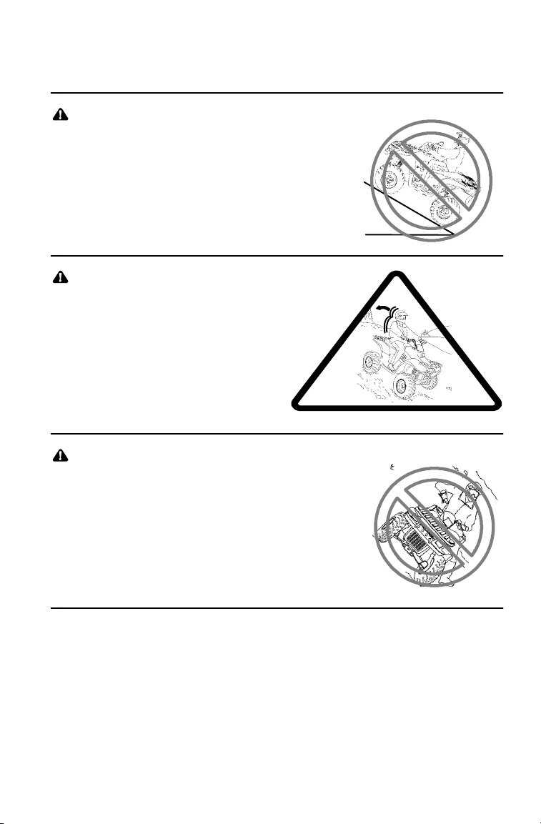
Always follow the procedures
outlined in this manual for braking if
you stall or roll backwards while
climbing a hill. Never back down a
hill. See page 31.
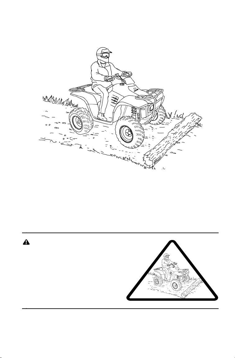
Always follow the procedures
outlined in this manual for
operating over obstacles.
See page 27.
Always follow the procedures
outlined in this manual for
operating on slippery or loose
surfaces. Use extra caution.
Always avoid skidding or
sliding. See page 26.
14
Page 17
Operator Safety
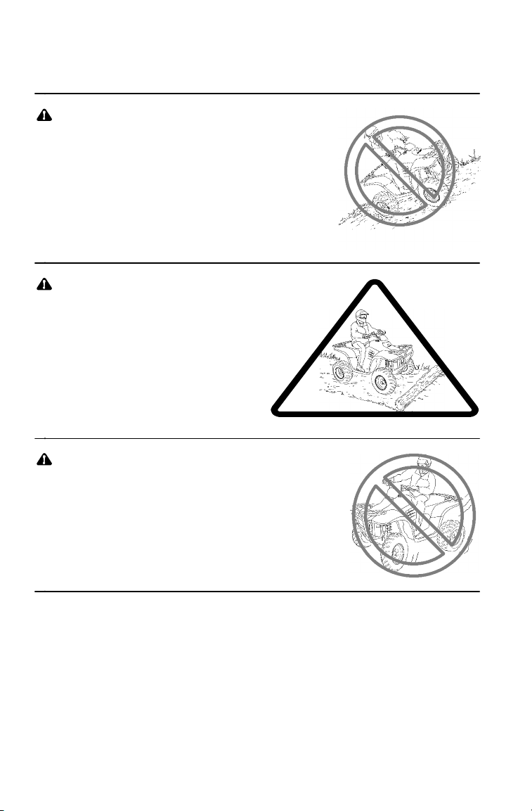
Always follow the
procedures outlined in
this manual for driving
through water. Never
drive through deep or
fast-flowing water. See
page 34.
Always follow the procedures
outlined in this manual for
driving in reverse. See page 36.
Always use the size
and type of tires specified
for your Quadricycle.
Maintain the proper
tire pressure.
SAFETY
15
Page 18
SAFETY
Operator Safety
Never modify a
Quadricycle through
improper installation
or use of accessories.
Never exceed the stated
load capacity for your
Quadricycle. Cargo
must be properly
distributed and securely
attached. Reduce
speed and follow the
instructions in this manual
for carrying cargo or
towing. Allow a greater distance for braking.
Never operate the Quadricycle on
a frozen body of water.
1/3
2/3
2/3
1/3
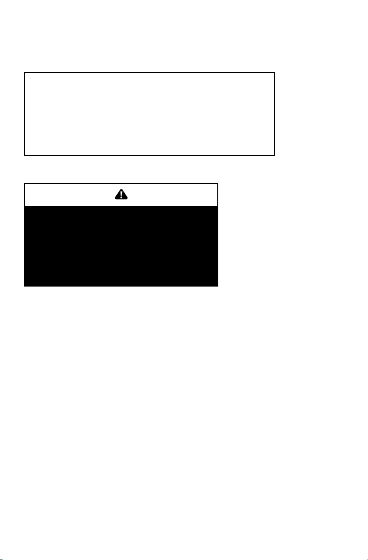
Operating on paved surfaces may
seriously affect the handling and
control of the Quadricycle and
could result in loss of control,
accident, and/or injury.
Avoid sudden turns or swift
movement of the
handlebars.
16
Page 19
SAFETY
Operator Safety
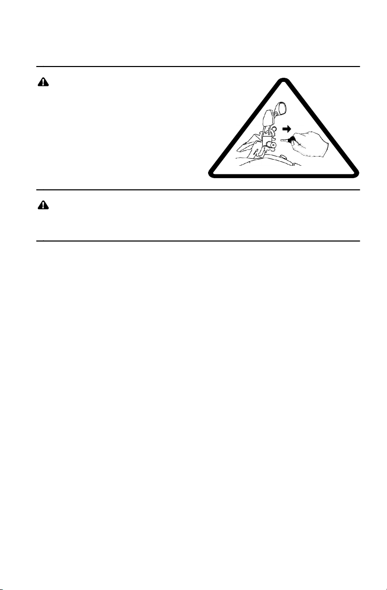
Always remove the ignition
key when the vehicle is not
in use to prevent
unauthorized use or
accidental starting.
Always keep combustible materials away from the exhaust
system. Exposure of combustibles to hot components could
result in a fire.
FOR MORE INFORMATION ABOUT QUADRICYCLE SAFETY,
call Polaris at 1-800-342-3764.
17
Page 20
SAFETY
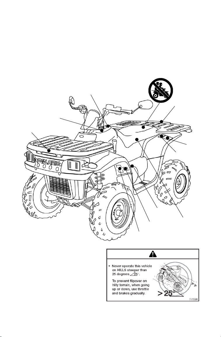
Safety Decals and Locations
Warning decals have been placed on the vehicle for your protection.
Read and follow the instructions on each decal carefully. If a decal
becomes illegible or comes off, contact your Polaris dealer to purchase
a replacement. Replacement safety decals are provided by Polaris at no
charge. The part number is printed on the decal.
C
G
J
G
F
E
Decal Text
Never operate this vehicle on
hills steeper than 25 degrees.
To prevent flipover on hilly
terrain, when going up or
down, use throttle and brakes
gradually.
18
D
A
B
H
A
Page 21
Safety Decals and Locations
SAFETY
BC
NO STEP
D
19
Page 22
SAFETY
Safety Decals and Locations
Decal Text
NEVER ride as a passenger.
Passengers can cause
a loss of control, resulting
in SEVERE INJURY or DEATH.
TIRE PRESSURE IN PSI (KPa):
FRONT 5 (34.5) REAR 5 (34.5)
MAXIMUM WEIGHT CAPACITY (Gross Vehicle Weight)
INCLUDING MACHINE, DRIVER AND CARGO IS 845 LBS. (383 kg)
MAXIMUM CARGO CAPACITY 200 LBS. (91 kg)
Read Owner’s Manual for more detailed loading information.
WARNING
7172566
E
7173301
DO NOT TOW FROM RACK OR BUMPER.
Vehicle damage or tipover may result causing severe
injury or death. Tow only from tow hooks or hitch.
Max. Rack Loads: Front 75 lbs. (34 kg) Rear 125 lbs. (57 kg)
7172666
20
F
G
Page 23

Safety Decals and Locations
SAFETY
S Operation of this vehicle
without the air filter
element will severely damage the
engine.
S Clean pre-filter element often,
more frequent cleaning
required in dusty conditions.
Do not operate vehicle without
pre-filter.
ATTENTION
and adjustments are required
depending on temperature
and altitude. See your Owner’s
Manual.
S Specific
carburetor jetting
Factory setting:
40_ to 80_ F. at 0-3000 feet
(5_ to 27_ C. at 0-900 meters).
7170007
H
Decal Text (H)
S Operation of this vehicle without the air filter element will severely
damage the engine.
S Clean pre-filter element often, more frequent cleaning required in
dusty conditions. Do not operate vehicle without pre-filter.
S Specific carburetor jetting and adjustments are required depending
on temperature and altitude. See your Owner’s Manual.
Factory setting:
40_ to 80_ F. at 0-3000 feet (5_ to 27_ C. at 0-900 meters).
OVERRIDE
SWITCH
Reverse speed is
limited.
Reverse override
is controlled by the
override switch.
See your Owner’s
Manual.
7079906
J
21
Page 24
SAFETY
Safety Decals and Locations
Hitch Decal
TRAILER MAX WEIGHT:
850 LBS. (386 KG) ON LEVEL GROUND
HITCH MAX. VERTICAL WEIGHT: 85 LBS. (39 KG)
Recoil Decal
Recoil handle must be firmly
seated to prevent water en try.
Drain starter motor if wat er
enters. See owner ’s manual
7172562
7170915
22
Page 25
SAFETY
Safe Riding Gear
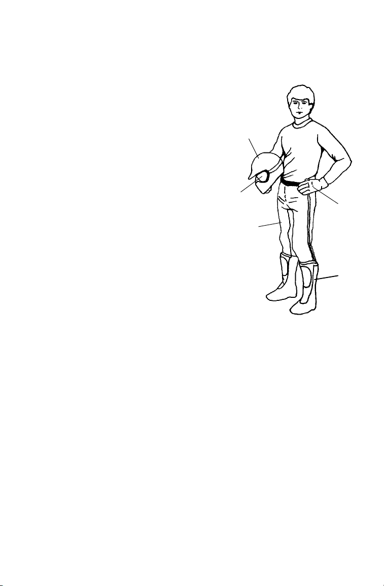
Always wear protective clothing to reduce the chance of injury.
1. Helmet
Always wear a helmet that meets or
exceeds established safety standards. A
helmet can prevent a severe head injury.
2. Eye Pro tectio n
Wear shatterproof goggles or a
shatterproof helmet face shield. Use a
lens anti-fogging product to keep them
clean.
3. Gloves
Wear off-road style gloves with knuckle
pads.
4. Boots
Wear strong over-the-calf boots with
heels, like moto-cross boots.
5. Clothing
Wear long sleeves and long pants to protect
arms and legs. Riding pants with kneepads
and a jersey with shoulder pads provide the
best protection. Do not wear loose clothing
that can get entangled in the vehicle, tree
branches or shrubs.
1
2
5
3
4
23
Page 26
SAFETY
Driving Safely
Driving Procedures
1. Sit upright. Keep your feet on the footrests. Keep both hands on the
handlebars.
2. Start the engine and allow it to warm up, then shift the transmission
into gear.
3. Check your surroundings and determine your path of travel.
4. Release the parking brake.
5. Slowly squeeze the throttle lever toward the handlebar to begin
driving. Squeeze the throttle lever further to increase speed.
6. Drive slowly. Practice maneuvering and using the throttle and brakes
on level surfaces.
24
Page 27
Driving Safely
Making Turns
1. To make a turn, steer in the
direction of the turn, leaning
your upper body to the inside of
the turn while supporting your
weight on the outer footrest.
Use the same leaning technique
for turning in reverse.
2. Practice turning at slow speeds
before attempting to turn at
faster speeds.
Never operate at
excessive speeds. Travel
and turn at speeds
appropriate for the terrain,
visibility, operating
conditions and your
experience.
10
SAFETY
30
20
40
0
50
Always follow the procedures
outlined in this manual for
turning. Never turn sharply at
excessive speeds, which can
lead to vehicle overturn.
25
Page 28
SAFETY
Driving Safely
Driving on Slippery Surfaces
Whenever driving on slippery or loose surfaces such as wet trails,
gravel, snow or ice, follow these precautions:
1. Slow down before driving onto slippery surfaces.
2. Use extra caution.
3. Be alert. Watch the trail. Avoid quick, sharp turns.
NOTE: To correct a rear wheel skid, turn the handlebars in the same
direction as the skid and shift body weight forward.
Always follow the procedures
outlined in this manual for
operating on slippery or loose
surfaces. Use extra caution.
Always avoid skidding or
sliding.
26
Page 29
SAFETY
Driving Safely
Driving Over Obstacles
1. Always check for obstacles before operating in a new area. Serious
injury or death can result if your vehicl e comes in contact with a
hidden obstacle.
2. Be alert. Watch the terrain. Use extra caution.
3. Never operate over large obstacles.
4. Avoid hazards such as logs, rocks and low branches.
Always follow the procedures
outlined in this manual for
operating over obstacles.
27
Page 30
SAFETY
Driving Safely
Driving Downhill
Whenever descending a hill,
follow these precautions:
1. Check the terrain carefully.
2. Avoid hills with excessively
slippery or loose surfaces.
3. Never go down a hill at high
speed.
4. Slow down.
5. Avoid going down a hill at an
angle, which can cause the
vehicle to pitch sharply to one side.
6. Drive straight downhill.
7. Shift your weight rearward.
8. Apply the foot brake slightly toaidinslowing.
9. Know how to use the hand brake.
Always follow the procedures
outlined in this manual for driving
downhill and for braking on
hills.
Never operate at
excessive speeds. Travel
and turn at speeds
appropriate for the terrain,
visibility, operating
conditions and your
experience.
28
10
30
20
40
0
50
Page 31

SAFETY
Driving Safely
Sidehilling
Avoid crossing the side of a hill (sidehilling) if possible. If sidehilling
is necessary, follow these precautions:
1. Slow down.
2. Avoid hills with excessively slippery or loose surfaces.
3. Shift your weight uphill.
4. Avoid crossing the sides of steep hills.
5. Keep your feet on the footrests.
6. Steer slightly into the hill.
NOTE: If the vehicle begins to tip, quickly turn the front wheels
downhill (if possible) or dismount on the uphill side
immediately!
Always follow the procedures
outlined in this manual for crossing
the side of a hill.
Neverattempttoturnthe
Quadricycle around on any hill until
you’ve mastered (on level ground)
the turning technique outlined in this
manual.
29
Page 32

SAFETY
Driving Safely
Driving Uphill
Whenever traveling uphill, follow these precautions:
1. Avoid steep hills (25_ maximum).
2. Check the terrain carefully.
3. Avoid hills with excessively slippery or loose surfaces.
4. Shift your weight uphill.
5. Drive straight uphill.
6. Keep your feet on the footrests.
7. Drive at a steady rate of speed to avoid stalling.
8. Be alert. Be prepared to take emergency action. This may include
dismounting quickly.
9. Never open the throttle suddenly or make sudden gear changes.
10. Never go over the top of a hill at high speed.
30
<25_
Page 33

SAFETY
Driving Safely
Driving Uphill
If all forward speed is lost:
Keep your weight uphill.
If the vehicle begins rolling downhill, never apply engine power. Never
apply the hand brake while rolling backwards.
Apply the foot brake gradually. When fully stopped, apply the hand
brake as well. Lock the hydraulic parking brake.
Dismount on the uphill side, or to either side if the vehicle is pointed
straight uphill. Turn the vehicle around and remount, following the
procedure described on page 32.
Always follow the procedures
outlined in this manual for
climbing hills. Avoid climbing
hills steeper than 25_.
>25_
Always follow the procedures outlined
in this manual for braking if you stall
or roll backwards while climbing a hill.
Never back down a hill.
31
Page 34

SAFETY
Driving Safely
Turning Around on a Hill
If the vehicle stalls while climbing a hill, never back down the hill!
Use the K-turn to turn around.
2.4 m
1. Stop the vehicle. Keep your weight uphill.
2. Lock the hydraulic parking brake.
3. Leave the transmission in forward gear. Turn the engine off.
4. Dismount on the uphill side of the vehicle, or on the left if the
vehicle is pointing straight uphill.
5. Stay uphill of the vehicle and turn the handlebars full left.
6. Squeeze the brake lever to release the parking brake.
7. Slowly release the brake lever and allow the vehicle to roll around
to your right until it’s pointing across t he hill or slightly
downward.
32
Page 35

SAFETY
Driving Safely
Turning Around on a Hill
8. Lock the hydraulic parking brake. Remount from the uphill side.
Keep your weight uphill.
9. Apply the foot brake.
10. With the transmission still in forward, start the engine.
11. Squeeze and release the brake lever to release the parking brake.
12. Release the foot brake and drive slowly downhill. Control speed
with the foot brake until the vehicle is on level ground.
Always follow the procedures
outlined in this manual for
climbing hills. See page 30.
>25_
Always follow the procedures
outlined in this manual for crossing
the side of a hill. See page 29.
33
Page 36

SAFETY
Driving Safely
Driving Through Water
Follow t hese procedures when operating through water:
1. Check water depth and current before crossing.
2. Avoid operating in
water deeper than the
bottom of the footrests (1).
If it’s unavoidable,
travel slowly, balance
your weight carefully
and avoid sudden
movements. Maintain a
slow and steady forward
motion. Do not make
sudden turns, stops or
throttle changes.
3. Choose a crossing where
both banks have gradual i nclines.
4. Drive slowly.
5. Avoid rocks and obstacles.
6. Wet brakes may have reduced stopping ability. Always test your
brakes after leaving water. If necessary, apply them lightly several
times to allow friction to dry out the pads.
1
Always follow the
procedures outlined in
this manual for driving
through water. Never
drive through deep or
fast-flowing water.
34
Page 37

SAFETY
Driving Safely
Driving Through Water
CAUTION
If the vehicle stops while fully submerged, major engine damage
can result if the machine is not thoroughly inspected. Take the
vehicle to your dealer before starting the engine.
If your vehicle becomes fully immersed, and it’s impossible to take it
to a dealer before starting it, follow the steps described on page 92.
Have the vehicle serviced by your dealer promptly.
NOTE: If water has been ingested into the transmission (PVT),
follow the procedure on page 59.
35
Page 38
SAFETY
Driving Safely
Driving in Reverse
Follow these precautions when operating in reverse:
1. Avoid backing downhill.
2. Always check for obstacles or
people behind the vehicle
before backing.
3. Drive slowly.
4. Apply the foot brake
lightly for stopping.
5. Avoid turning at
sharp angles.
6. Never apply t he throttle
suddenly.
7. Do not use the override switch unless additional power is required
for vehicle movement. Use with caution.
NOTE: Reverse speed is greatly increased when the override switch
is used. Do not operate at full throttle. Apply just enough
throttle to maintain the desired speed.
CAUTION
Excessive throttle operation while in the speed limit mode may
cause fuel to build in the exhaust, resulting in engine popping
and/or engine damage.
Always follow the procedures
outlined in this manual for
driving in reverse.
36
Page 39

SAFETY
Driving Safely
ParkingonanIncline
Avoid parking on an incline. If it’s unavoidable, follow these
precautions:
1. Turn the engine off.
2. Place the transmission in gear.
3. Lock the mechanical parking brake.
4. Always block the rear wheel s on the downhill side.
5. Turn the fuel valve off.
37
Page 40

SAFETY
Driving Safely
Hauling Cargo and Towing
WARNING
Overloading the vehicle or carrying or towing cargo improperly
can alter vehicle handling and may cause loss of control or brake
instability. Always follow these precautions when hauling cargo.
S Read and understand the load distribution warnings listed on the
vehicle warning labels.
S Never exceed the stated load capacity for this vehicle.
S REDUCE SPEED AND ALLOW GREATER DISTANCES FOR
BRAKING WHEN HAULING CARGO OR TOWING. Use extreme caution when applying brakes. Avoid situations that require backing downhill.
S When operating over rough or hilly terrain, reduce speed, cargo
and towed load to maintain stable driving conditions.
S Do not obstruct the headlight when loading the front rack.
S CARRY LOADS AS LOW ON THE RACK AS POSSIBLE. Car-
rying a load high on the rack raises the center of gravity of the
vehicle and creates a less stable operating condition. Reduce
load weight when cargo is high. Secure off-centered loads that
cannot be centered and operate with extra caution.
S CARRYING A LOAD on only one rack may cause the vehicle to
overturn. Split the load between the front rack and rear rack,
with 1/3 in the front and 2/3 in the back. Do not exceed load capacities. See specifications beginning on page 108.
S SECURE ALL LOADS BEFORE OPERATING. Unsecured
loads can create unstable operating conditions, which could
result in loss of control of the vehicle.
S OPERATE ONLY WITH STABLE AND SAFELY ARRANGED
LOADS. When handling off-centered loads that cannot be
centered, securely fasten the load and operate with extra
caution. Always attach the tow load to the hitch point
designated for your vehicle.
S WHEN LOAD EXTENDS BEYOND RACK SIDES, stability and
maneuverability may be adversely affected, causing the machine to overturn. Use extreme caution.
S TOWING is approved OFF-ROAD ONLY. Operating a Quadri-
cycle/trailer combination on public roads is prohibited.
S TOWING SPEED should never exceed 16 km/h. Never exceed
8 km/h when towing loads in rough terrain, while cornering, or
while ascending or descending hills.
38
Page 41

SAFETY
Driving Safely
Hauling Cargo and Towing
2/3
1/3
Towin g
Towing is approved OFF-ROAD ONL Y. Operating a
Quadricycle/trailer combination on public roads is prohibited. Do not
exceed the maximum capacities when towing. Do not tow any trailer
on a grade steeper than 15°.
Trail Boss 330
QUADRICYCLE
Maximum Towed Load
(Level Ground)
386 kg 38.6 kg
Maximum Vertical Hitch
Weight
39
Page 42
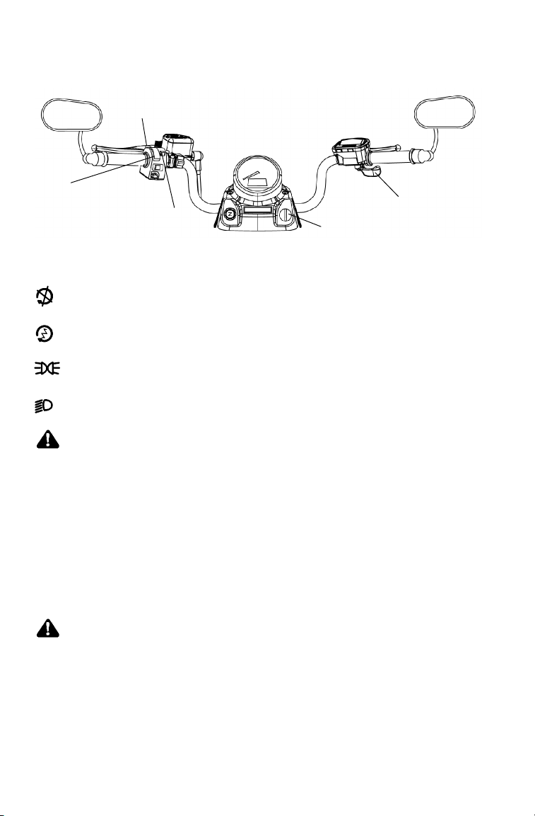
FEATURES AND CONTROLS
Controls/Instruments
(2)
(4)
(3)
(1) Main Key Switch
Turn the main key switch off to stop the engine and end all
electrical power to the vehicle.
Turn the switch on to engage the starter.
After starting the engine, release the key to the RUNNING
LIGHTS position.
Turn the switch to LIGHTS ON to switch the headlights on.
(1)
WARNING
Do not attach a large key fob or key ring to the main switch. It
may contact the gas tank cap when turning, causing an
interruption to the electrical system and an unexpected engine
shut-down during operation. This could result in serious injury or
death.
(5)
(2) Speedometer Mode/Override Switch (Reverse Speed Limiter)
To gain additional power while operating in reverse, cancel the reverse
speed limit function by pressing the override switch before opening the
throttle.
WARNING
Activating the override switch with the throttle open and while
operating in reverse can cause loss of control. Do not activate
the override switch while the throttle is open.
40
Page 43
FEATURES AND CONTROLS
Controls/Instruments
(3) Engine Stop Switch
Move the stop switch to the
OFF position to stop the
engine. All electrical power to
the vehicle will end. The
engine will not start or run
when the switch is in the OFF
position.
Move the stop switch to the
ON (RUN) position before
attempting to start the engine.
(3)
OFF
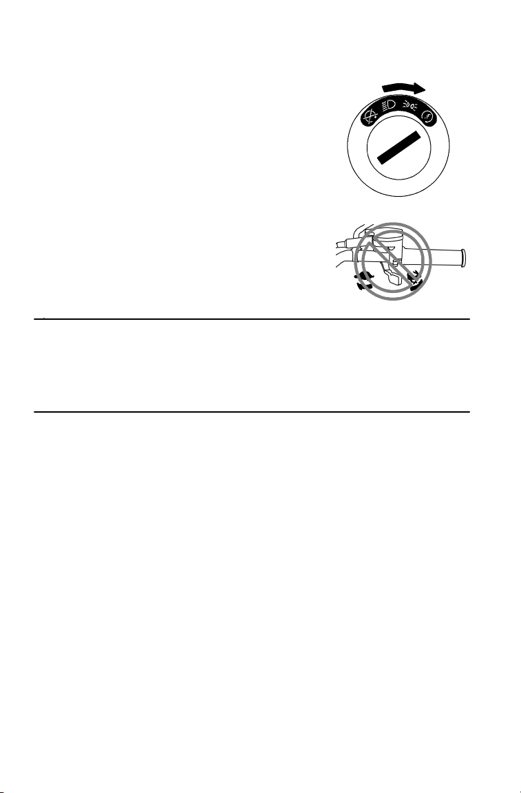
(4) Light Switch
(4)
Toggle the lights from high beam to
low beam.
NOTE: The lights do not operate
unless the main key
switch is on and the
engine stop switch is in
the RUN position.
(5) Throttle lever
Press the throttle lever to
increase engine speed and
vehicle movement. Release
the lever to reduce engine
speed and vehicle movement.
(5)
WARNING
Failure to check or maintain proper operation of the throttle
system can result in an accident if the throttle lever sticks during
operation. Check the lever for proper operation before starting the
engine. Check occasionally during operation.
Do not start or operate a Quadricycle with sticking or improperly
operating throttle controls.
Contact your dealer for repair if throttle problems arise.
OFF
41
Page 44

FEATURES AND CONTROLS
Controls/Instruments
(10)
(6)
(11)
(13)
(12)
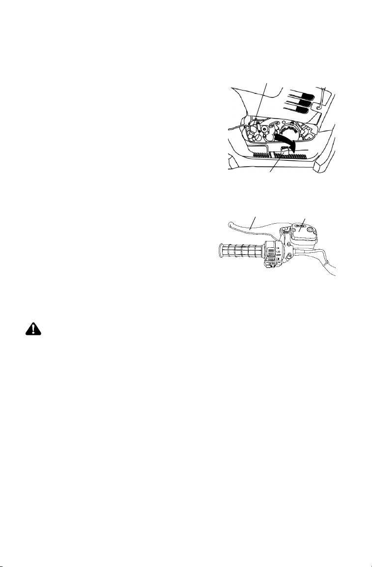
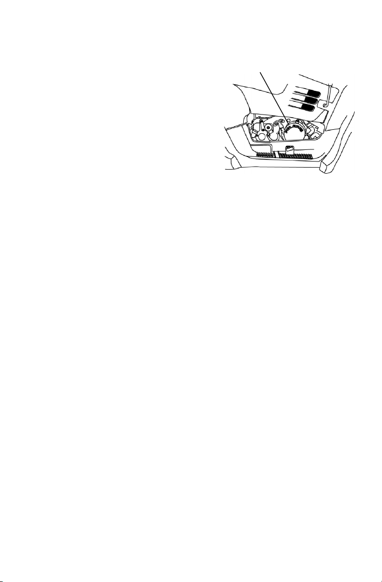
(6) Electronic Throttle Control (ETC)
(8) (9)
(7)
(14)
ETC causes the engine to stop
if the throttle cable sticks in
an open position when the
operator releases the throttle
lever.
WARNING
The Electronic Throttle Control (ETC) stops the engine in the
event of a throttle system malfunction. Do not modify the ETC
system or replace it with other throttle mechanisms.
(7) Choke Knob
The choke assists in starting a cold engine. See page 57.
(8) Horn
Press the horn button to
alert others of your
presence.
(13)
(6)
OFF
42
(8)
Page 45

FEATURES AND CONTROLS
Controls/Instruments
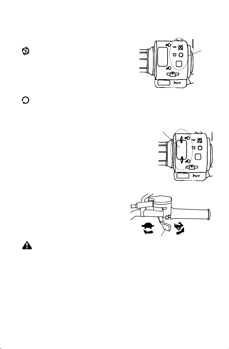
(9) Hazard Warning Switch
Push the hazard warning switch
to cause all turn indicators to
flash simultaneously. Use this
feature to alert others of an
emergency or other situation
requiring caution.
(10) Rear Brake Lever
The left brake lever operates the hydraulic rear brakes only. See page
44.
(11) Parking Brake Lever
The right brake lever is used as a mechanical parking brake only. See
page 45.
(12) Turn Indicator
Push the toggle switch either left or right
to activate the corresponding turn signal.
Return the toggle to the center position to
end the signal.
(13) Mirrors
Use the mirrors to assist in traffic
maneuvers. Always check and adjust the
(12)
mirrors before driving the Quadricycle.
(9)
OFF
L
R
(14) Instrument Panel
View certain vehicle functions on the instrument panel. The
corresponding lights illuminate when the feature is activated.
:
N
HOT
Left Turn Engine Hot Neutral High Beam Right Turn
43
Page 46
FEATURES AND CONTROLS
Brakes
Foot Brake
The all-wheel foot brake (1) is located on
the right footrest. The foot brake operates
both front and rear brakes. Press the brake
pedal forward with your foot to engage
the all-wheel brakes.
The master cylinder (2) is located near the
foot brake. Inspect and maintain the brake
fluid level as outlined in this manual. See
pages 56 and 75.
Rear Brake Lever
The left brake lever (1) operates the
hydraulic rear brakes only. Squeeze the
brake lever toward the handlebar to
apply the rear brakes.
If the rear wheels begin to skid or slide
while using this brake, reduce lever
pressure.
Inspect and maintain the brake fluid level in the master cylinder (2) as
recommended. See pages 56 and 75.
2
1
1
2
WARNING
Aggressively applying the rear brake when backing down a hill
may cause rear tipover.
Aggressively applying the rear brake while moving forward may
cause the rear wheels to skid and result in loss of control.
Read this owner’s manual and understand the operation of all
brake systems on this vehicle.
Always use caution whenever applying only the rear brakes.
44
Page 47
FEATURES AND CONTROLS
Brakes
WARNING
Operating the Quadricycle while the parking brake is engaged
could result in an accident and serious injury or death. Always
check to be sure the parking brake is disengaged before
operating.
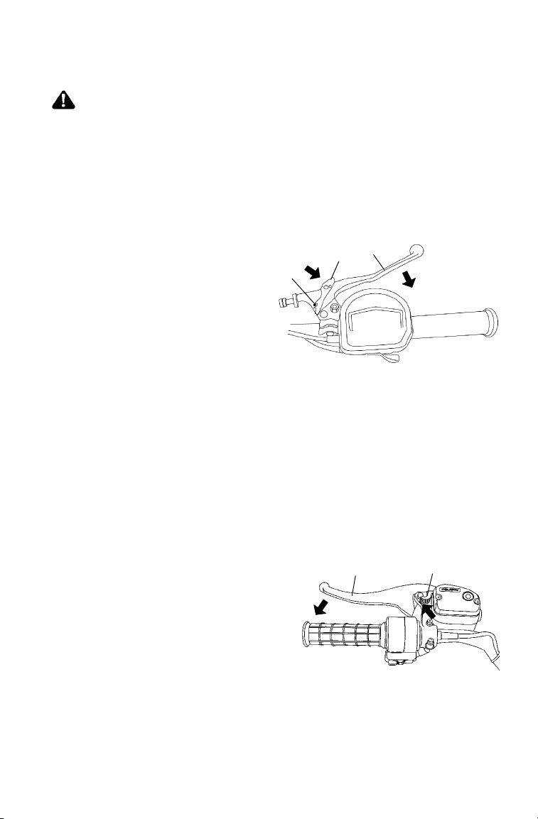
Locking the Parking Brake (Mechan ical)
The right brake lever is used as a mechanical parking brake only. It is
not intended to be used as a brake lever.
1. Squeeze the right brake
lever (1) toward the
handlebar.
2. Move the park brake
lock (2) toward the
handlebar until the peg (3)
fits into the slot on the
lever. Release the lock lever.
3. To release the parking brake lock, squeeze and release the brake
lever. The parking brake will release automatically.
NOTE: The parking brake may relax if left on for a long period of
time. Always block the wheels to prevent rolling. Never
depend on the parking brake alone if the vehicle is parked on
a hill. Always block the wheels to prevent rolling.
3
1
2
Locking the Parking Brake (Hydraulic)
The hydraulic parking brake lock is a temporary lock. Do not rely on
the hydraulic parking brake when leaving the vehicle unattended.
Always lock the mechanical parking brake.
1. Squeeze the left brake lever (1).
2. Move the park brake lock (2) to
the locked position. This will
prevent the lever from returning
to the released position.
3. To release the parking brake
lock, squeeze and release the
brake lever. The parking brake
will release automatically.
1
2
45
Page 48

FEATURES AND CONTROLS
Steering Lock
Lock the steering to prevent unauthorized use or theft of the vehicle.
1. Turn the handlebars t o the full left position.
2. Insert the steering lock key and turn it clockwise.
3. Remove the key.
4. Reverse the procedure to unlock the steering.
NOTE: Place the steering lock keys in a safe place. The lock must
be replaced if the keys are lost.
46
Page 49

FEATURES AND CONTROLS
Fuel Tank
The fuel tank filler cap (1) is located directly below the handlebar.
Refuel with either leaded or unleaded gasoline with a minimum of 87
octane.
WARNING
S Gasoline is highly flammable and explosive under certain
conditions.
S Use extreme caution whenever handling gasoline.
S Refuel with the engine stopped. Refuel outdoors or in a well
ventilated area.
S Never fill a fuel container while it’s in the cargo box. Static
electricity between the box and container could cause a spark.
S Do not smoke or allow open flames or sparks in or near the
area where refueling is performed or where gasoline is stored.
S Do not overfill the tank. Do not fill the tank neck.
S If gasoline spills on your skin or clothing, immediately wash it off
with soap and water and change clothing.
S Turn the fuel valve off whenever the vehicle is stored or parked.
Fuel Valve
The fuel valve (2) is located on the left side panel.
RES
OFF
Turn the valve off before storage and when
transporting.
ON
Turn the valve on for normal
operation.
RES
Turn the valve to the reserve setting if
the main fuel supply is exhausted.
Refuel as soon as possible. Reserve
fuel range is about 11-16 km.
NOTE: Return the valve to the ON
position after refueling.
OFF
ON
2
1
47
Page 50

FEATURES AND CONTROLS
Transmission Gear Selector
The transmission gear selector (1)
is located on the right side of the
vehicle.
Whenever the vehicle is left
unattended, place the transmission
in gear and lock the mechanical
parking brake.
F: Forward Gear
N: Neutral
R: Reverse
1
CAUTION
Shifting gears with the engine speed above idle or while the
vehicle is moving can cause transmission damage. Stop the
vehicle, release the throttle and move the lever to the desired
gear. See your dealer if you experience any shifting problems.
FNR
48
Page 51
FEATURES AND CONTROLS
Recoil Starter
If the battery is too weak to start
the engine, use the recoil starter (1).
Follow the starting procedures on
page 57, cranking the engine with
the recoil starter instead of the
main key switch.
1. Grasp the recoil starter rope
handle tightly. Pull slightly
until the starter mechanism
engages.
2. Pull the rope abruptly to start the engine.
1
CAUTION
Extending the starter rope too far will cause damage to the recoil
assembly. Do not extend the starter rope so far that it stops.
If the starter rope handle is not seated properly, water may enter
the recoil housing and damage components. Make sure the
handle is fully seated on the recoil housing, especially when
traveling in wet areas.
49
Page 52

FEATURES AND CONTROLS
Instrument Cluster
The instrument cluster senses vehicle speed from the right front wheel.
It measures distance as well as hours of operation. It also includes a
reverse speed limiter function that limits reverse speed to about 11-14
km/h. See page 40 for additional information.
3
2
1
1. Rider Information Center
2. Speedometer needle (In addition to showing vehicle speed, the
needle flashes when a warning condition exists.)
3. Speedometer
CAUTION
To prevent damage to the instrument cluster, wash the
Quadricycle by hand or with a garden hose using mild soap.
Do not use alcohol to clean the instrument cluster.
Immediately wash off any gasoline that splashes on the
instrument cluster.
50
Page 53

FEATURES AND CONTROLS
Instrument Cluster
Rider Information Center
The rider information center is located in the instrument cluster. All
segments will light up for 2.5 seconds at start-up.
NOTE: If the instrument cluster fails to illuminate, a battery
over-voltage condition may have caused it to shut down to
protect the electrical system. If this occurs, take the
Quadricycle to your Polaris dealer.
1. Gear Indicator - As
2
3
4
the shift lever is
moved, this indicator
shows the gear the
5
transmission is in.
H = High Range
(Forward)
N = Neutral
R = Reverse
6
2. Engine Hour Display Indicator
1
3. Service Interval/Diagnostic Mode Indicator
4. Odometer/Tachometer/Tripmeter/ Hour Meter
5. Check Engine W arning Indicator - “HOT” will display when the
engine is overheating. Turn off the engine or serious damage could
result.
6. Mode Indicator
51
Page 54

FEATURES AND CONTROLS
Instrument Cluster
Rider Information Center
The reverse override button on the left handlebar is also the mode
button. Use the mode button to toggle through the four (4) standard
modes of the rider information center.
NOTE: The transmission cannot be in reverse.
Mode 1 - Odometer
The odometer records the total distance traveled by the vehicle since
manufacture.
Mode 2 -Trip Meter
The trip meter records the distance traveled on each trip if it’s reset
before each trip. To reset the trip meter, select the trip meter mode.
Press and hold the mode button (override button) until the total
changes to 0.
NOTE: The trip meter displays a decimal point, but the odometer
does not.
Mode 3 - Hour Meter
The hour meter logs the total hours the engine has been in operation.
Mode 4 - Tachometer
The tachometer displays engine RPM. Small fluctuations in the RPM
are normal due to changes in humidity, temperature and elevation.
52
Page 55

FEATURES AND CONTROLS
Instrument Cluster
Rider Information Center
Diagnostic Mode
The diagnostic mode is for informational purposes only. Please return
your Quadricycle to your dealer for all major repairs.
The wrench icon will display when the gauge is in the diagnostic
mode.
Steps to enter the diagnostic mode:
1. Turn the main key switch off and wait 10 seconds.
2. Shift the transmission into neutral or park.
3. Hold the mode button and turn the main key switch on.
4. Release the switch as soon as the display is activated.
5. Use the mode button to toggle through the six (6) diagnostic
screens.
Three (3) ways to leave the diagnostic mode:
S Shift the transmission out of neutral.
S Turn the main key switch off and on.
S Move the tires.
Screen 1: Battery voltage
Screen 2: Tachometer
Screen 3: AWD diagnostic
This screen indicates whether or not current is flowing through the
AWD system.
Screen 4: Gear circuit diagnostic
This screen displays the resistance value (in ohms) being read at the
gear switch input.
53
Page 56

FEATURES AND CONTROLS
Instrument Cluster
Rider Information Center
Diagnostic Mode
Screen 5: Programmable service interval
The programmable service interval provides a convenient reminder
when routine maintenance is due. This feature is pre-set at 50 hours.
You must enable the programmable service interval before it can be
used.
When set, the hours of operation are subtracted from t he set hours until
0 is reached. The wrench icon will flash quickly for five seconds each
time the engine is started as a reminder that service is due.
Setting the Service Interval
1. Press and hold the mode/override button until the wrench icon
flashes. Release the button.
2. Press the button once to advance the setting by one hour. Press and
hold the button to advance the hours at a faster pace.
3. When the desired time increment is displayed, release the button.
When the wrench stops flashing, service hours are set.
NOTE: If you scroll past the intended number, hold the button down
until the count turns over to 0. You can then reset the
number.
Disabling the Service Interval
1. Toggle to the service interval mode.
2. Press and hold the mode button for approximately seven (7)
seconds. The service i nterval is disabled when the word OFF
displays.
Screen 6: Miles/Kilometers toggle
The display in the tripmeter and odometer can be changed to display
either kilometers or miles. The current display mode will be shown as
either KM or MP.
1. Press and hold the mode button until the letters flash.
2. Press and release the mode button once. When the display stops
flashing, the mode has been set.
54
Page 57

OPERATION
Break-In Period
The break-in period for your new Polaris Quadricycle is the first ten
hours of operation, or the time it takes to use the first two full tanks of
gasoline. No single action on your part will increase the life and
performance of your Quadricycle more than following the procedures
for a proper break-in. Careful treatment of a new engine will result in
more efficient performance and a longer life.
Do not operate at full throttle or high speeds for extended periods
during the first three hours of use.
Perform the following procedures carefully.
1. Fill the fuel tank with gasoline.
2. Check the oil level on the dipstick. Add oil if necessary.
Seepage67.
3. Select an open area that allows room to familiarize yourself with
vehicle operation and handling.
4. Drive slowly. Vary throttle positions. Do not operate at sustained
idle.
5. Perform regular checks on fluid levels, controls and areas outlined
on the daily pre-ride inspection checklist. See page 56.
6. Pull only light loads.
7. Perform the break-in oil change at one month.
55
Page 58

OPERATION
Pre-Ride Inspection
Pre-Ride Checklist
Item Remarks See
Page
Brake system Ensure proper operation 74
Brake fluid Ensure proper level 75
Foot brake Ensure proper operation 44
Front suspension Inspect, lubricate if necessary 65
Rear suspension Inspect, lubricate if necessary 65
Steering Ensure free operation --
Tires Inspect condition and pressure 82
Wheels / fasteners Inspect, ensure fastener tightness 81
Drive chain Inspect condition, lubricate frequently 83
Frame nuts, bolts, fasteners Inspect, ensure tightness --
Fuel and oil Ensure proper levels 47, 67
Throttle Ensure proper operation 41, 79
Indicator lights / switches Ensure operation 40
Engine stop switch Ensure proper operation 41
Air filter, pre-filter Inspect, clean 85
Air box sediment tube Drain deposits whenever visible --
Headlamp Check operation, apply Polaris dielec-
tric grease when lamp is replaced
Brake light / tail lamp Check operation, apply Polaris dielec-
tric grease when lamp is replaced
Riding gear Wear helmet, goggles, protective
clothing
86
88
23
56
Page 59

OPERATION
Starting the Engine
WARNING
Engine exhaust contains poisonous carbon monoxide and can
cause loss of consciousness resulting in serious injury or death.
Never run an engine in an enclosed area or indoors.
CAUTION
Operating the vehicle immediately after starting could cause
engine damage. Allow the engine to warm up for several minutes
before operating.
1. Position the vehicle on a
level surface.
2. Sit on the vehicle.
3. Lock the mechanical
parking brake.
4. Turn the fuel valve on.
RES
5. Move the engine stop switch to RUN.
OFF
ON
6. If the engine is cold, pull
the choke knob (1) out until it
stops. A warm engine will not
require the use of the choke.
FULL ON
HALF ON
1
OFF
NOTE: Make sure the choke is off during operation. Excess fuel
washing into the engine oil will increase wear on engine
components.
57
Page 60
OPERATION
Starting the Engine
7. Turn the ignition key to the ON
position to engage the start er. Activate
the starter for a maximum of five
seconds, releasing the key when the
engine starts.
NOTE: Do not press the throttle while
8. If the engine does not start, release the
9. Repeat steps 7 and 8 until the engine starts.
10. If the engine slows or stops, position the choke knob half way in.
11. Vary engine RPM slightly with the throttle. When the engine idles
starting the engine.
starter and wait five seconds.
smoothly, push the choke all the way in.
58
Page 61

OPERATION
Polaris Variable Transmission
Preventing Belt Slip / Failu re
Belt slip creates heat that destroys belts and causes outer clutch covers
to fail. Avoid heavy pulling and extended low speed operation.
WARNING
Do not modify any component of the PVT system. Doing so may
reduce its strength so that a failure may occur at a high speed.
The PVT system has been precision balanced. Any modification
will cause the system to be out of balance, creating vibration and
additional loads on components.
The PVT system rotates at high speeds, creating large amounts
of force on clutch components. Extensive engineering and
testing has been conducted to ensure the safety of this product.
However, as the owner, you have the following responsibilities to
make sure this system remains safe:
S Always follow all recommended maintenance procedures. See
your dealer as outlined in the owner ’s manual.
S This PVT system is intended for use on Polaris products only.
Do not install it in any other product.
S Always make sure the PVT housing is securely in place during
operation.
PVT Drying
If water is ingested into the PVT system, dry it before operating the
vehicle.
1. Remove the drain plug. Drain the water. Reinstall the drain plug.
2. Place the transmission in neutral. Lock the mechanical parking
brake. Start the engine.
3. Apply varying throttle for 10-15 seconds to expel the moisture and
air-dry the belt and clutches. Do not hold the throttle wide open.
4. Allow the engine RPM to return to idle speed, then shift the
transmission to the lowest available range.
5. Test for belt slippage. If the belt slips, repeat the process.
6. Take the vehicle to your dealer for service promptly.
59
Page 62
EMISSION CONTROL SYSTEMS
Noise Emission Control System
Do not modify the engine, intake or exhaust components, as doing so
may affect compliance with governmental noise level requirements.
Spark Arrestor
Your Polaris vehicle has a spark arrestor that was designed for on-road
and off-road operation. It is required that this spark arrestor remain
installed and functional when the vehicle is operated.
Crankcase Emission Control System
This engine is equipped with a closed crankcase system. Blow-by
gases are forced back to the combustion chamber by the intake system.
The system does not allow the blow-by gases to enter the atmosphere.
Exhaust Emission Control System
The emissions from the exhaust of
this vehicle are controlled by
engine design, including
factory-set fuel delivery and
ignition. The engine and related
components must be maintained
at Polaris specifications to achieve
optimal performance.
The emissions label (1) is located
on the recoil cover.
Adjustment to engine idle is the only adjustment recommended that the
operator perform. Any other adjustments should be performed by an
authorized Polaris dealer.
1
Electromagnetic Interference
This spark ignition system complies with USA requirements, Canadian
ICES--002 and European directives 89/336/EEC and 97/24/EC.
60
Page 63

MAINTENANCE AND LUBRICATIO N
Periodic Maintenance Chart
Maintenance intervals in the following chart are based upon average
riding conditions. Vehicles subjected to severe use must be inspected
and serviced more frequently.
Severe Use Definition
S Frequent immersion in mud, water or sand
S Racing or race-style high RPM use
S Prolonged low speed, heavy l oad operation
S Extended idle
S Short trip cold weather operation
NOTE: Service and adjustments are critical. If you are not familiar
with safe service and adjustment procedures, have a
qualified Polaris dealer perform these operations.
The programmable service interval mode on the instrument cluster will
help determine when maintenance service i s due. See page 54.
Maintenance Chart Key
" Perform these procedures more frequently for vehicles subjected to
severe use.
E Emission Control System S ervice
J Have an authorized Polaris dealer perform these services.
WARNING
Improperly performing the procedures marked with a J could
result in component failure and lead to serious injury or death.
Have an authorized Polaris dealer perform these services.
61
Page 64

MAINTENANCE AND LUBRICATIO N
j
onpage5
6
Periodic Maintenance Chart
Perform all services at whichever maintenance interval is reached first.
Item Maintenance Interval
(whichever comes first)
Hours Calendar Kilometers
Steering -- Pre-Ride --
J
Front suspension -- Pre-Ride --
"
Rear suspension -- Pre-Ride --
"
Tires -- Pre-Ride --
Brake fluid level -- Pre-Ride --
"
Brake lever travel -- Pre-Ride --
"
Brake systems -- Pre-Ride --
Wheels/fasteners -- Pre-Ride --
Drive chain -- Pre-Ride --
Frame fasteners -- Pre-Ride --
Engine oil level -- Pre-Ride --
"
Make adjustments as needed. See Pre-Ride Checklist
on page 56.
Remarks
.
E
Air filter, pre-filter -- Daily -- Inspect; clean often
"
E
Air box sediment
"
tube
E
Headlamp/tail
lamp
Air filter,
"
main element
E
Recoil housing -- Weekly -- Drain water as needed,
Brake pad wear 10 Monthly 100 Inspect periodically
"
J
Battery 20 Monthly 200 Check terminals; clean; test
Transmission oil 25 Monthly 250 Inspect level; change yearly
"
Engine breather
"
filter
E
Engine oil change
"
(break-in)
E
General
"
lubrication
" Perform these procedures more often for vehicles subjected to severe use.
-- Daily -- Drain deposits when visible
-- Daily -- Check operation; apply
-- Weekly -- Inspect; replace as needed
25 Monthly 250 Inspect; replace if necessary
25 1M 250 Perform a break-in oil
50 3M 500 Lubricate all fittings, pivots,
dielectric grease if replacing
check often if operating in
wet conditions
change at one month
cables, etc.
E Emission Control System Service
J Have an authorized Polaris dealer perform these services.
62
Page 65

MAINTENANCE AND LUBRICATIO N
Periodic Maintenance Chart
Item Maintenance Interval
(whichever comes first)
Hours Calendar Kilometers
Carburetor float
bowl
Throttle Cable/
J
ETC Switch
E
Choke cable 50 6M 500 Inspect; adjust; lubricate;
J
E
Carburetor air
E
intake ducts/
flange
Drive belt 50 6M 500 Inspect; adjust; replace as
Engine oil change 100 6M 1000 Perform a break-in oil
"
E
Oil filter change 100 6M 1000 Replace with oil change
"
50 6M 500 Drain bowl periodically and
prior to storage
50 6M 500 Inspect; adjust; lubricate;
replace if necessary
replace if necessary
50 6M 500 Inspect ducts for proper
sealing/air leaks
needed
change at one month
Remarks
E
Valve clearance 100 12 M 1000 Inspect; adjust
J
E
Fuel system 100 12 M 1000) Check for leaks at tank cap,
J
E
Fuel filter 100 12 M 1000 Replace yearly
J
lines, fuel valve, filter, pump,
carburetor; replace lines
every two years
E
Engine mounts 100 12 M 1000 Inspect
"
Exhaust muffler/
pipe
Spark plug 100 12 M 1000 Inspect; replace as needed
J
100 12 M 1000 Inspect
E
Ignition Timing 100 12 M 1000 Inspect
J
E
Wiring 100 12 M 1000 Inspect for wear, routing,
"
" Perform these procedures more often for vehicles subjected to severe use.
security; apply dielectric
grease to connectors
subjected to water, mud, etc.
E Emission Control System Service
J Have an authorized Polaris dealer perform these services.
63
Page 66

MAINTENANCE AND LUBRICATIO N
Periodic Maintenance Chart
Item Maintenance Interval
(whichever comes first)
Hours Calendar Kilometers
Clutches (drive
J
and driven)
Front wheel
J
bearings
Brake fluid 200 24 M 2000 Change every two years
J
Spark arrestor 300 36 M 3000 Clean out
Idle speed -- Adjust as needed
E
Toe adjustment -- Inspect periodically; adjust
J
Foot brake and
"
rear brake
J
Mechanical
"
parking brake
J
Headlight aim -- Adjust as needed
" Perform these procedures more often for vehicles subjected to severe use.
100 12 M 1000 Inspect; clean; replace worn
parts
100 12 M 1600 Inspect; replace as needed
when parts are replaced
-- Inspect daily; adjust as
needed
-- Inspect daily; adjust cable as
needed
Remarks
E Emission Control System Service
J Have an authorized Polaris dealer perform these services.
64
Page 67

MAINTENANCE AND LUBRICATIO N
Torque Symbol
= Torque the item as specified.
Lubrication Recommendations
Check and lubricate all components at the intervals outlined in the
Periodic Maintenance Chart beginning on page 61. Items not listed in
the chart should be l ubricated at the General Lubrication interval.
Item Lube Method
Engine Polaris Premium 4
Brakes DOT 3 fluid only See page 74.
Transmission Premium AGL
Drive chain(s) O-ring chain lube
(1) Ball Joint Premium U-Joint
(2) Swing Arm
Bushings
(3) Axle Housing
Synthetic 0W40
Synthetic
Gearcase Lube
or SAE 80/90
Grease
See page 66.
See Page 72.
Lubricate as often as required and
before each ride in wet conditions
Locate fittings and grease.
(3)
(2)
(1)
65
Page 68

MAINTENANCE AND LUBRICATIO N
Engine Oil
Polaris Premium 4 Synthetic Oil is the only oil recommended for use
in this engine. Use of another API certified “SH” oil is acceptable as
long as it’s 0W-40. Oil may need to be changed more frequently if
Polaris Premium 4 is not used. See page 103 for t he part numbers of
Polaris products.
Always check and change the engine oil at the intervals outlined in the
Periodic Maintenance Chart beginning on page 61.
CAUTION
Using a non-recommended oil may cause serious engine damage.
Use only Polaris Premium 4 All Season Synthetic Oil or an API
certified 0W-40 “SH” oil. Never substitute or mix oil brands.
66
Page 69

MAINTENANCE AND LUBRICATIO N
Oil Check
1. Position the vehicle on a
level surface.
2. Place the transmission in
neutral.
3. Lock the mechanical
parking brake.
4. Start the engine. Allow it to
idle for 30 seconds.
5. Turn the engine off.
6. Remove the dipstick.
Wipe it clean.
FNR
7. Reinstall the dipstick completely.
8. Remove the dipstick. Check the oil
level.
9. Add oil as needed to bring the level
between the minimum and maximum
marks.
67
Page 70

MAINTENANCE AND LUBRICATIO N
Oil and Filter Change
Always change the engine oil at the intervals outlined in the Periodic
Maintenance Chart beginning on page 61. Always change the oil filter
when changing oil. Change the oil more often if the vehicle is routinely
subjected to:
S operation in dusty or wet conditions.
S operation when air temperat ure is below -12° C.
S short trips at -12° to -1° C. (engine fails to reach operating tempera-
ture).
CAUTION
If the Quadricycle is left without oil in the system for extended
periods, the oil pump may lose its prime, which could result in
engine damage. Always replace the oil and filter within a few
hours of draining the oil. Do not allow the vehicle to be without oil
overnight.
1. Use Polaris-recommended
products.
S Oil filter
S 0W/40 oil
1. Position the vehicle on a
level surface.
2. Place the transmission in
neutral.
3. Lock the mechanical
parking brake.
4. Start the engine. Allow it
to idle for two minutes.
5. Turn the engine off.
68
FNR
Page 71

MAINTENANCE AND LUBRICATIO N
Oil and Filter Change
6. Place a drain pan under the
vehicle.
7. Remove the drain plug.
8. Drain the oil.
CAUTION
Hot oil may result in serious burns. Do not allow hot oil to contact
skin.
9. Reinstall the drain plug with a new
sealing washer.
=19 N-m
10. Place towels under t he oil
filter.
11. Using an oil filter wrench (4),
turn the filter counterclockwise to
remove it.
12. Clean the filter sealing area on
the engine.
4
69
Page 72

MAINTENANCE AND LUBRICATIO N
Oil and Filter Change
13. Lubricate the filter o-ring.
14. Install the new oil filter.
After the filter contacts the
engine surface, turn it 1/2
turn by hand.
15. Remove the dipstick.
16. Add two .95 liter bottles of
0W/40 oil.
17. Reinstall the dipstick.
18. Start the engine. Allow it to idle for
two minutes.
19. Turn the engine off.
20. Check for oil leaks.
21. Check the oil level. Add oil as needed
to bring the level between the minimum
(MIN) and maximum (MAX) marks.
22. Discard used oil and filter properly.
70
Page 73
MAINTENANCE AND LUBRICATIO N
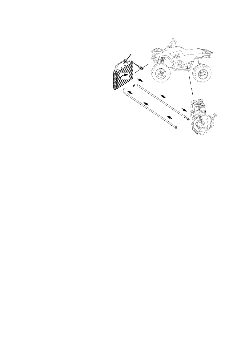
Engine Oil Cooler Maintenance
The oil cooling system
requires little maintenance
other than keeping the
cooler (1) free of mud and
debris.
1
CAUTION
Do not use a high
pressure washer to
remove debris from the
cooler. The pressure
may damage the
cooling fins. Use only
low pressure water.
71
Page 74
MAINTENANCE AND LUBRICATIO N
Transmission Oil Check
See page 65 for recommended lubricants. See page 103 for the part
numbers of Polaris products.
1. Position the vehicle on a
level surface.
2. Place the transmission in
gear.
3. Lock the mechanical
parking brake.
FNR
4. Remove the dipstick.
Wipe it clean.
5. Reinstall the dipstick
completely.
6. Remove the dipstick.
Check the oil level.
7. Maintain the level
between the minimum
(MIN) and maximum
(MAX) marks.
8. Add fluid as needed.
Do not overfill.
9. Reinstall the dipstick.
72
Page 75

MAINTENANCE AND LUBRICATIO N
Transmission Oil Change
1. Position the vehicle on a
level surface.
2. Place the transmission in
gear.
3. Lock the mechanical
parking brake.
FNR
4. Loosen the jam nut (1).
5. Turn the adjuster bolt (2)
inward.
6. Remove the drain plug (3).
Wipe it clean.
7. Drain the fluid into a drain pan.
8. Install a new sealing washer.
Reinstall the drain plug.
=19 N-m
9. Turn the adjuster bolt outward
until it touches the frame, and
then turn an additional 1/2 turn.
10. Tighten the jam nut securely
while holding the adjuster bolt.
11. R emove the dipstick.
12. Add 335 ml of the recommended fluid.
13. Reinstall the dipstick.
14. Check for oil leaks.
1
2
3
73
Page 76

MAINTENANCE AND LUBRICATIO N
Brakes
Under normal operation, a diaphragm extends into the reservoir as fluid
level drops. If the fluid l evel is low and the diaphragm is not extended,
a leak is likely. The brake system should be inspected by your dealer.
Fill the reservoir as needed whenever the cover is loosened or removed
to ensure proper diaphragm operation. Use Polaris DOT 3 brake fluid.
Do not overfill.
NOTE: Reservoir levels will decrease as brake pads become worn.
When checking the fluid level, the vehicle must be on level
ground with the handlebars straight. If the fluid level is low,
check brake pad thickness before adding brake fluid. DO
NOT OVERFILL.
Brake Check
Perform the following checks to keep the brake systems in good
operating condition. Check more often if brakes are used heavily
during normal operation.
WARNING
Do not overfill the reservoirs. An over-full master cylinder may
cause brake drag or brake lock-up, which could cause brake loss
or loss of control. Maintain brake fluid at the recommended level.
1. Check the brake systems regularly for
fluid leaks.
2. Check the brakes for excessive travel
or spongy feel.
3. Check the brake pads for wear,
damage or looseness. Replace pads
when they are worn to 1 mm.
4. Check the security and surface
condition of the brake discs.
1mm
74
Page 77
MAINTENANCE AND LUBRICATIO N
Brakes
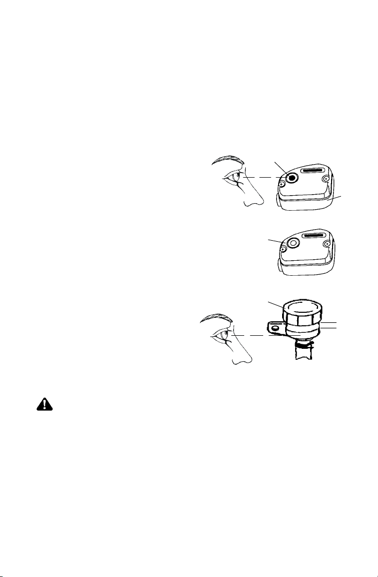
Brake Fluid Check
Check brake fluid levels before each use of the vehicle.
The brakes should feel firm when they’re applied. Spongy or weak
brakes may i ndicate a fluid leak or low fluid level. A low fluid level
may also mean that brake pads are worn and need to be replaced. Do
not operate the vehicle with spongy or weak brakes. See your dealer for
service.
Master Cylinder (Handlebar)
2
The master cylinder (1) is
located on the left
handlebar. View t he fluid
level through the indicator
window (eye) on the top of
the master cylinder.
A dark eye (2) indicates a
3
full fluid level.
A clear eye (3) indicates a
low fluid level.
Master Cylinder (Foot Brake)
4
The foot brake master
cylinder (4) is located under
the right rear fender. View the
fluid level through the res ervoir
body. Fluid level i s full at the
MAX mark. Add brake fluid if the
level reaches the MIN mark.
WARNING
Once open, a bottle of brake fluid absorbs moisture from the air,
which causes the boiling temperature of the brake fluid to drop.
This can lead to early brake fade and the possibility of accident.
Do not store opened brake fluid. Properly discard any unused
portion.
Max
1
Min
75
Page 78

MAINTENANCE AND LUBRICATIO N
Steering / Suspension
Toe Alignment
Use the following procedure to check the t oe alignment of the vehicle.
The recommended toe alignment is 3-6 mm toe out.
1. Set the handlebars in a
straight-ahead position.
2. Place stands (1) in front of the
vehicle, perpendicular to the
rear tires.
3. Tie an elastic string around the
stands, making sure the string
just touches the side surface of
the rear tires on each side of
the vehicle and goes around the
stands in front of the vehicle (2).
4. Measure the distance from the
string to the rim at the front
and rear of the front rim (3).
The rear measurement should
be 2 to 3 mm more t han the
front measurement.
2
3
NOTE: If you discover improper
alignment, see your Polaris
dealer for service.
WARNING
Do not attempt to adjust alignment. All steering adjustments
should be performed by an authorized Polaris dealer.
Rear Springs
The rear shock absorber springs are
adjustable. Use the spanner wrench (1) in
the tool kit.
Rotate the adjuster (2) clockwise to increase
or counterclockwise to decrease spring
tension.
76
2
1
1
Page 79
MAINTENANCE AND LUBRICATIO N
Steering / Suspension
Steering Assembly
Check the steering assembly of
the vehicle periodically for loose
nuts and bolts. If loose nuts and
bolts are found, see your Polaris
dealer for service before
operating the vehicle.
Handlebar Adjustment
1. Remove the two hex
screws (1) from the
instrument panel (2).
Remove the instrument
panel.
2. Loosen (do not
remove) all four
handlebar bolts.
3. Adjust the handlebar
to the desired height.
NOTE: Make sure the
handlebars do
not contact the
gas tank or any part of
the machine when turned
fully to the left or right.
4. Torque the two front bolts (3), then torque the two rear bolts (4).
1
4
2
3
14-17 N-m
=14-17 N-m
NOTE: A gap of up to 3 mm should remain at the rear bolts.
WARNING
Improper adjustment of the handlebars or incorrect torquing of
the adjuster block tightening bolts can cause limited steering or
loosening of the handlebars, resulting in loss of control. Follow
the adjustment procedures exactly, or see your Polaris dealer for
service.
77
Page 80

MAINTENANCE AND LUBRICATIO N
Carburetor Idle Adjustment
IMPORTANT: Your Polaris vehicle is calibrated at the factory for
optimal performance at altitudes ranging from zero to 1800 meters and
at temperatures of 4 degrees C. or higher. Above 1800 meters the
engine air/fuel mixture becomes too rich and the engine loses
approximately 3% of its power for each 300 meter increase in
elevation. Although this power cannot be regained, adjustments t o the
carburetor and drive system can be made to allow more efficient
operation. Optional jets and clutch components, available from your
Polaris dealer, are required for operation above 1800 meters. Jetting is
required only when operating below 4 degrees C. at 1800 meters and
lower.
NOTE: Operating the engine with improper jetting can cause poor
performance, overheating or engine damage. See your
Polaris dealer for more information about jetting.
If necessary, the carburetor can be
adjusted.
1. Place the transmission in neutral.
2. Lock the mechanical parking
FNR
brake.
3. Operate the engine for about five minutes.
4. Adjust the carburetor idle screw (1)
clockwise to raise RPM or
counterclockwise to lower RPM.
1
-- R P M
+RPM
78
Page 81

MAINTENANCE AND LUBRICATIO N
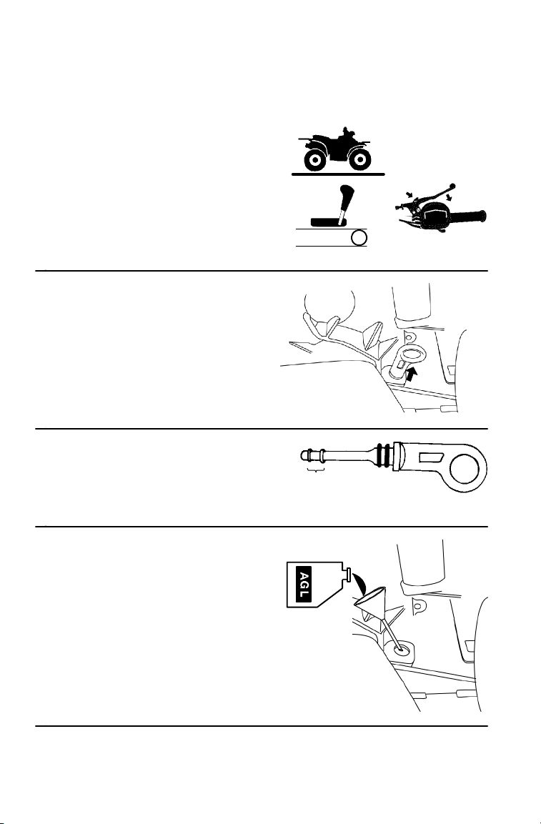
Throttle Cable Freeplay Adjustment
1. Locate the throttle cable
adjuster (1) on the
handlebar.
2. Slide the boots (2) off
the cable adjuster
sleeve (3). Loosen the
adjuster (4).
3. Turn the adjuster until 1.6-3.2 mm
of freeplay exists at the lever.
NOTE: Move the throttle lever
back and forth while
adjusting.
4. Tighten the adjuster.
Slide the boots (2) over
the cable adjuster until
they touch at the
midpoint of the adjuster.
NOTE: Engine RPM should
not increase when
steering is turned full
left or right. Readjust
cable freeplay if this
occurs.
2
2
3
2
1
2
4
1.6-3.2 mm
2
4
2
79
Page 82
MAINTENANCE AND LUBRICATIO N
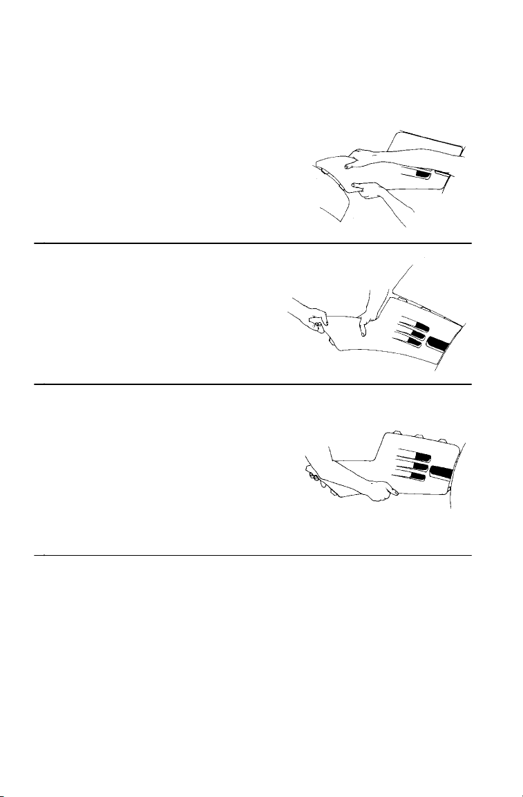
Side Panel Removal
NOTE: Side panel removal may be difficult until the locking tabs and
1. Remove the seat.
2. Grasp the rear of the side
3. Place your hand on top of the
4. Pull the side panel upward to
Reinstallation
5. Align the tabs with the slots
6. Push the panel upward and
7. Bend the rear of the side panel
receivers have been snapped and unsnapped a few times.
panel near the rear cab. Pull
the panel forward and outward
quickly and firmly to
disengage the rear tabs.
side panel behind the fuel
tank. Push down quickly and
firmly to disengage the top
rear tabs.
disengage the front tabs.
on the front cab.
forward until the t abs lock.
and insert the two tabs into the
rear cab slots.
80
Page 83

MAINTENANCE AND LUBRICATIO N
Wheel Removal / Installation
CAUTION
Operating with improperly installed wheels will affect vehicle
handling and could cause an accident resulting in serious injury or
death. Always use original equipment size and type when
replacing tires. Install wheels properly.
1. Position the vehicle on a
level surface.
2. Place the transmission in
gear.
3. Lock the mechanical
parking brake.
FNR
4. Loosen the wheel nuts
slightly.
5. Safely place jackstands
under the vehicle.
6. Remove the wheel nuts
and remove the wheel.
7. Place the wheel on the hub.
8. Install the wheel nuts
finger tight.
9. Carefully remove the jackstands.
10. Torque the wheel nuts.
= 37 N-m Front Wheel
=68 N-m Rear Wheel
81
Page 84

MAINTENANCE AND LUBRICATIO N
Tires
Tire Tread Depth
Always replace tires when tread
depthiswornto3mmorless.
3mm
WARNING
Operating your vehicle with worn tires,
improperly inflated tires, non-standard
tires or improperly installed tires will
affect vehicle handling and could cause
an accident.
Maintain proper tire pressure as described on the decal on your
vehicle and in the specifications section of the owner’s manual
beginning on page 108.
Use only original equipment size and type when replacing tires.
Make sure the wheels are installed properly.
Replace tires when the tread depth measures 3 mm or less.
Wheel and Hub Tightening
Wheel hub and bearing tightness and spindle nut retention are critical
items. These services must be performed by an authorized dealer.
82
Page 85

MAINTENANCE AND LUBRICATIO N
Drive Chain
Always inspect the drive chain before operating the vehicle. Check for
damaged or missing o-rings or damaged rollers. Check for correct slack
adjustment. Maintain the stone guard-to-rear sprocket clearance at 3
mm. Lubricate the outer surfaces of the roller regularly.
Lubricate the drive chain as outlined in the Lubrication Chart on page
65.
High pressure water may damage components. Do not use high
pressure water. See page 99.
Rear Drive Chain Slack
Adjusting or operating the vehicle with improper rear drive chain slack
can result in severe damage to the transmission and drive components.
Always make sure the slack is within the stated specifications.
Check the amount of chain slack
in three different locations by
moving the vehicle slightly
forward. Measure the chain slack
at the tightest of the three
positions. At this point the chain
should have 4.8-9.5 mm
deflection.
Use the following procedure if
adjustment is required.
1. Loosen the chain guide.
2. Loosen the two eccentric
locking bolts (1).
3. Loosen the caliper mounting
bolt located on the left side
of the swing arm.
4. Insert a pin punch (2)
through the sprocket hub
and into the eccentric
housing.
1
4.8 - 9.5 mm
2
1
83
Page 86

MAINTENANCE AND LUBRICATIO N
Drive Chain
Rear Drive Chain Slack
5. Roll the vehicle forward or
backward to adjust the chain slack
to the proper tension. See t he
illustration for proper splice link
clip opening position (1).
6. Tighten the eccentric locking bolts
to 61 N-m.
7. Tighten the caliper mounting bolt to 20 N-m.
8. Remove the pin punch.
9. Roll the vehicle forward, checking chain tension in several places
around the chain. The chain is adjusted correctly when the tightest
portion of the chain has approximately 10 mm deflection.
10. Position the chain guide to allow 3 mm clearance and tighten the
retaining bolt to 7 N-m.
Fuel Filter
Replace the in-line fuel filter at the intervals
outlined in the Periodic Maintenance Chart
beginning on page 61. Do not attempt to
clean the fuel filter.
1
84
Page 87
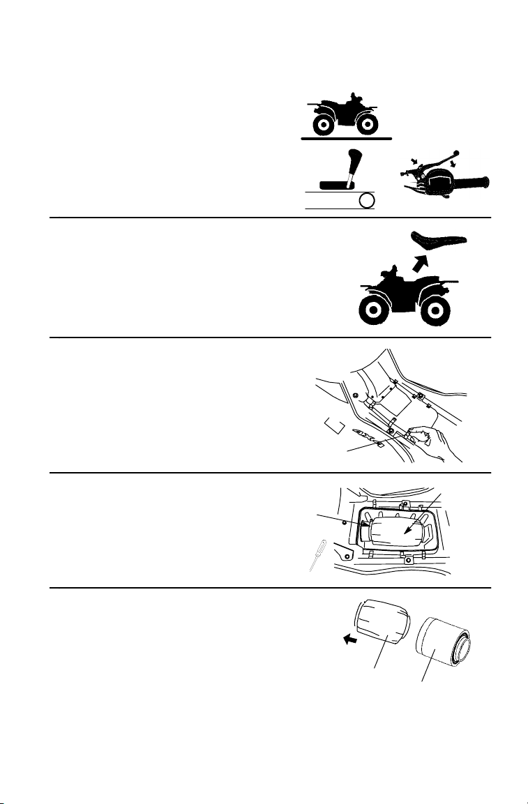
MAINTENANCE AND LUBRICATIO N
Air Filter
1. Position the vehicle on a
level surface.
2. Place the transmission in
gear.
3. Lock the mechanical
parking brake.
4. Remove the seat.
5. Unlatch the air box clips (1).
Remove the air box cover.
FNR
6. Loosen the hose clamp (2)
and remove the filter (3).
7. Remove the pre-filter (4) from the
filter (5). Wash the pre-filter in
soapy water . Rinse and air dry.
NOTE: Replace the filter if needed.
8. Reverse the steps t o reinstall all
components.
1
3
2
4
5
85
Page 88
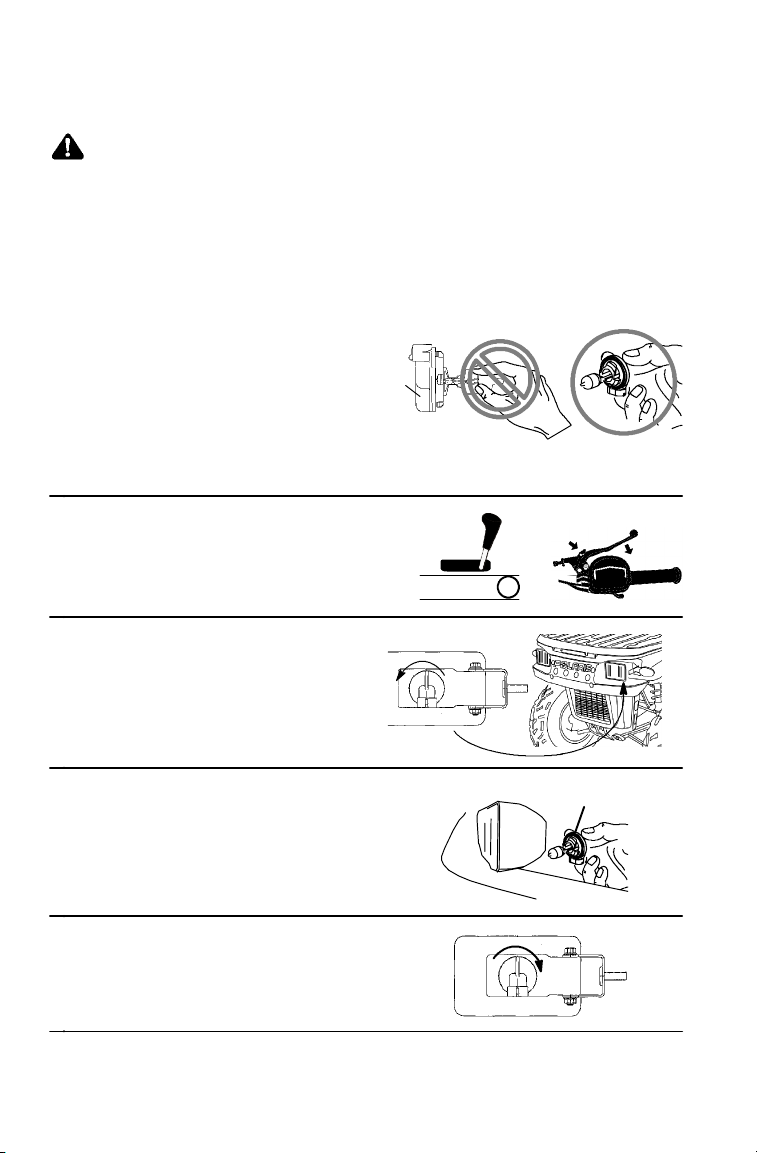
MAINTENANCE AND LUBRICATIO N
Lights
WARNING
Poor lighting can result in loss of control or an accident. Lights
become dirty during normal operation. Wash the headlights and
tail lights frequently.
Hot components can cause serious burns to skin. Do not service
the headlamps until they’ve cooled.
Headlight Replacement
When servicing a halogen lamp,
do not touch the lamp with bare
fingers. Hold the plastic part (1)
of the lamp. Oil from your skin
leaves a residue, causing a hot
spot that will shorten the life of
the lamp.
1. Place the transmission in gear.
2. Lock the mechanical parking
brake.
3. Turn the back of the
headlight counterclockwise.
1
FNR
4. Remove the headlamp (2).
5. Apply dielectric grease to
the socket.
6. Install the new headlamp.
7. Turn the back of the
headlight clockwise to
reinstall.
86
2
Page 89

MAINTENANCE AND LUBRICATIO N
Lights
High Beam Adjustment
7.6 m
x
x
5.1 cm
1. Position the vehicle on a level surface. The headlight should be
approximately 7.6 meters from a wall.
2. Place the transmission in
neutral.
3. Lock the mechanical parking
brake.
FNR
4. Measure the distance from the
floor to the center of the
headlight and make a mark on
the wall at the same height.
NOTE: Include rider weight on the seat when measuring.
5. Start the engine. Turn the headlight switch to high beam.
6. Observe the headlight aim on the wall. The most intense part of
the headlight beam should be aimed 5.1 cm below the mark placed
on the wall.
7. Loosen the pivot bolt and adjust the beam.
8. Tighten the bolt.
=3 N-m
87
Page 90
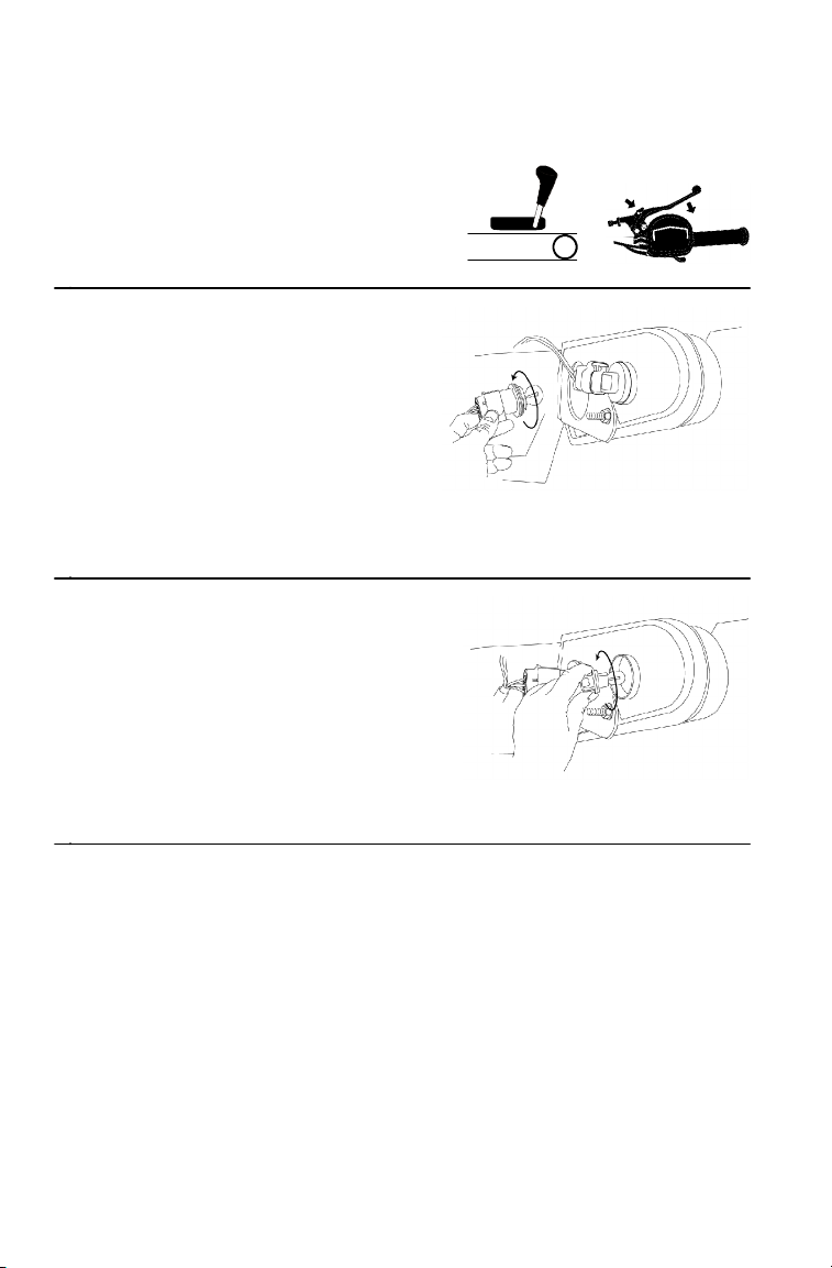
MAINTENANCE AND LUBRICATIO N
Lights
Taillight /Sign al Ligh t Replacement
1. Place the transmission in gear.
2. Lock the mechanical parking
brake.
3. Rotate the taillight socket
counterclockwise to remove it.
4. Remove the lamp.
5. Apply dielectric grease to the
socket.
6. Install the new lamp.
7. Test the lamp for proper
operation.
8. Reinstall all components in reverse order.
9. Rotate the turn signal socket
counterclockwise to remove it.
10. Remove the lamp.
11. Apply dielectric grease to the
socket.
12. Install the new lamp.
13. Test the lamp for proper operation..
14. Reinstall all components i n reverse order.
FNR
Indicator Lamp Replacement
1. Remove the instrument panel.
2. Using a small, straight-blade screwdriver, turn the base of the bulb
1/4 turn counterclockwise.
3. Remove the lamp. Use a needle-nose plier or similar tool.
4. Install the new lamp. Turn the lamp clockwise 1/4 turn.
5. Reinstall the instrument panel.
88
Page 91

MAINTENANCE AND LUBRICATIO N
Recoil Housing Drain
Always drain the recoil housing (1)
after operating the vehicle in wet
conditions. Always remove the drain
plug before storing the vehicle.
2
1
NOTE: Water will enter the recoil
housing if the starter
handle (2) is disengaged
from the rope guide when
under water.
1. Place the transmission in gear.
2. Lock the mechanical parking
brake.
3. Using a wrench, remove the
drain screw (3) on the bottom of
the recoil housing.
4. Reinstall the screw after draining
the housing.
FNR
3
89
Page 92
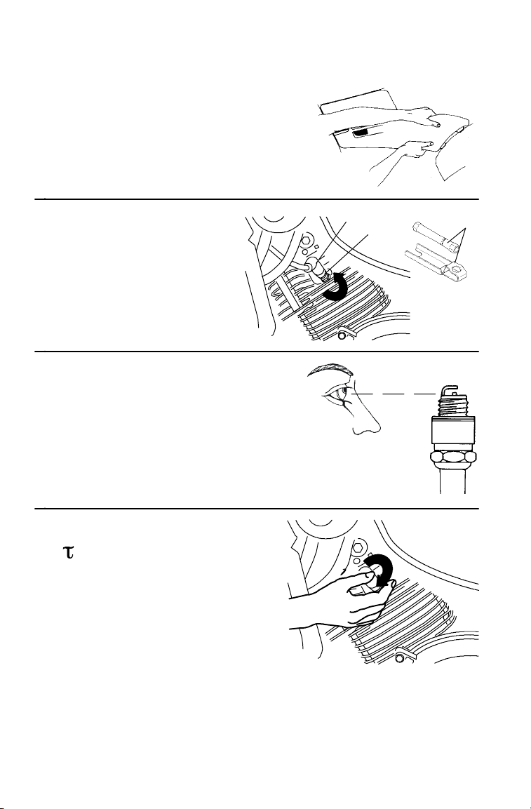
MAINTENANCE AND LUBRICATIO N
Spark Plugs
1. Remove the left side panel.
Seepage80.
2. Remove the spark
plug wire (1). Use the
sparkplugwrench(2)
to remove the spark
plug (3). Turn the plug
counterclockwise to
remove it.
3. Inspect the electrodes for
wear and carbon buildup.
Replace worn or fouled
plugs. Verify that the gap
is at specification before
installation.
4. Reinstall the spark plug.
=19 N-m
5. Reinstall the spark plug
wire.
1
3
2
90
19 N-m
Page 93

MAINTENANCE AND LUBRICATIO N
Spark Plugs
Spark Plug Condition
Normal
The insulator tip is tan or brown. There are few combustion deposits.
The electrodes are not burned or eroded. This indicates the proper type
and heat range for the engine and the service.
NOTE: The tip should not be white. A white insulator tip indicates
Fouled
The insulator tip is black. A damp film covers the firing end. There
may be a carbon layer over the entire nose. Generally, the electrodes
are not worn. General causes of fouling are excessive oil consumption,
improper use of the choke, or incorrect carburetion adjustments.
overheating, caused by use of an improper spark plug or
incorrect carburetion adjustments.
91
Page 94

MAINTENANCE AND LUBRICATIO N
Vehicle Immersion
CAUTION
If the vehicle stops while fully submerged, major engine damage
can result if the machine is not thoroughly inspected. Take the
vehicle to your dealer before starting the engine.
If your vehicle has been totally submerged in water and it’s impossible
to have it serviced before further operation, perform the following
procedure.
1. Move the vehicle out of
the water.
2. Turn the fuel valve off.
3. Remove the spark plug.
Seepage90.
4. Drain any water found in
the air box.
RES
OFF
ON
92
Page 95
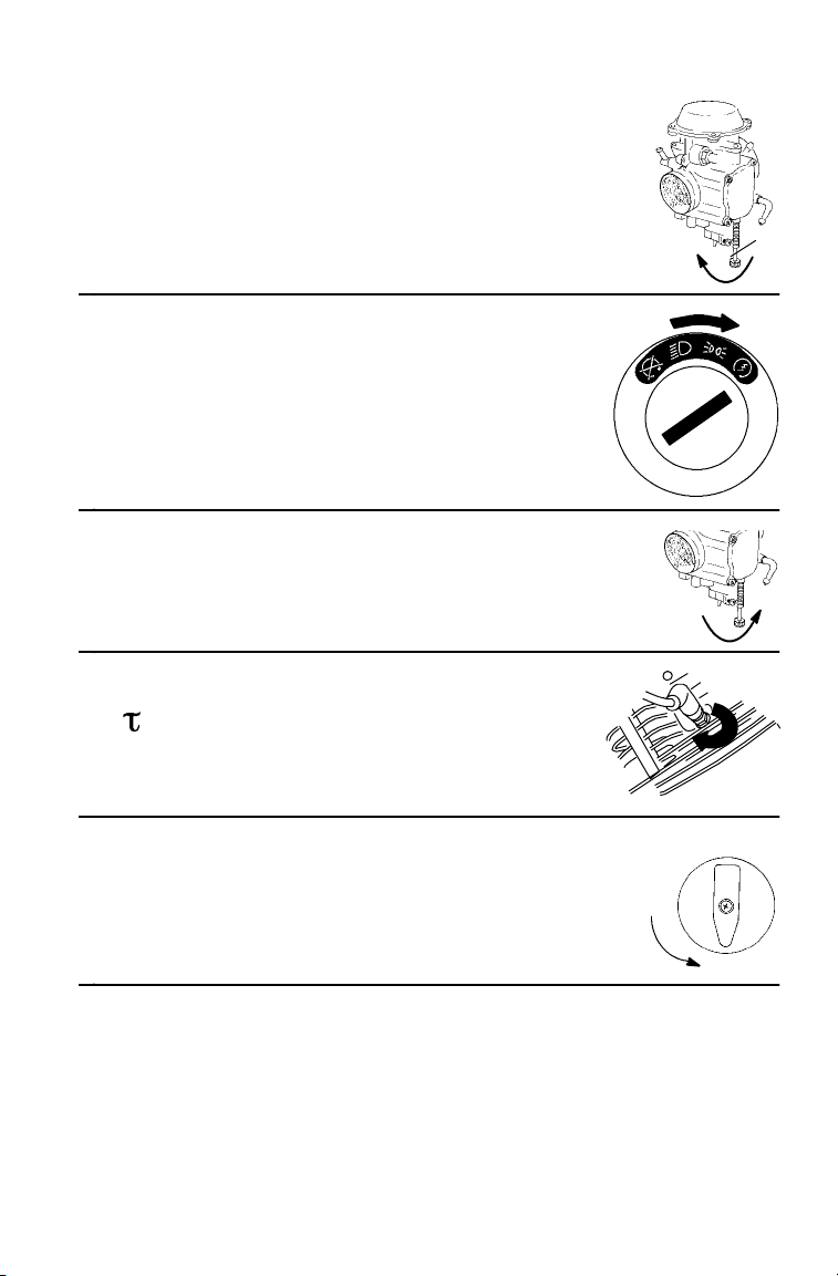
MAINTENANCE AND LUBRICATIO N
Vehicle Immersion
5. Loosen the carburetor drain screw (1) and
drain the carburetor.
6. Turn the ignition key to the ON
position to engage the start er.
Engage the starter for only 2-3
seconds.
7. Tighten the carburetor drain screw.
8. Reinstall the spark plug.
1
=19 N-m
9. Turn the fuel valve on.
OFF
RES
ON
10. Attempt to start the engine. If necessary, repeat the drying
procedure.
11. Have the vehicle serviced by your dealer promptly, whether you
succeed in starting it or not.
NOTE: If water has been ingested into the PVT, follow the procedure
for drying out the PVT. See page 59.
93
Page 96

MAINTENANCE AND LUBRICATIO N
Spark Arrestor
Occasionally, the spark arrestor may accumulate carbon, which can
restrict the exhaust i f left unattended. Purge the spark arrestor.
WARNING
Allow components to cool sufficiently before servicing. The
exhaust system can get extremely hot. Never run the engine in
an enclosed area or indoors. Exhaust contains poisonous carbon
monoxide gas. Never go under the vehicle while it’s inclined.
Remove any combustible materials from the area. Wear eye
protection and leather work gloves. Do not stand behind or in
front of the vehicle while purging.
1. Remove the arrestor clean-out plug
from the bottom of the muffler.
2. Place the transmission in neutral.
3. Lock the mechanical parking
brake.
FNR
4. Start t he engine.
94
Page 97

MAINTENANCE AND LUBRICATIO N
Spark Arrestor
5. Quickly squeeze and
release the throttle lever
several times to purge
carbon from the system.
6. If carbon comes out of the
exhaust, cover or plug the
exhaust outlet (1). Wear
leather gloves for
protection.
7. Lightly tap on the exhaust
pipe with a rubber m allet
while repeating step 5.
8. If particles are still
suspected to be in the
muffler, elevate the rear
of the vehicle 30 cm
higher than the front.
9. Lock the mechanical
parking brake.
10. Block the wheels.
1
30 cm
11. Repeat steps 5 to 7 until no more particles are expelled.
12. Turn the engine off. Allow the arrestor to cool.
13. Reinstall the arrestor plug and remove the exhaust outlet cover or
plug.
95
Page 98

MAINTENANCE AND LUBRICATIO N
Battery
WARNING
Improperly connecting or disconnecting battery cables can cause
sparks which could result in an explosion, causing serious injury or
death. When removing the battery, always disconnect the negative
(black) cable first. When reinstalling the battery, always connect the
negative (black) cable last.
Battery Removal
1. Place the transmission in gear.
2. Lock the mechanical parking
brake.
3. Disconnect the battery hold-down strap. Remove the battery cover.
4. Disconnect the black negative (--) cable first.
5. Disconnect the red positive (+) cable last.
6. Lift and remove the battery.
FNR
Battery Installation
Always install a fully charged battery. See page 97.
1. Place the battery in the battery holder.
2. Verify that cables are routed properly.
3. Connect the red positive (+) cable first.
4. Connect the black negative (--) cable last.
5. Install the battery cover.
6. Attach the hold-down strap.
96
Page 99

MAINTENANCE AND LUBRICATIO N
Battery
Battery Storage
Whenever the vehicle is not used for a period of three months or more,
remove the battery from the vehicle. Verify that it’s fully charged, and
store it out of the sun in a cool, dry place. Check battery voltage each
month during storage and recharge as needed to maintain a full charge.
NOTE: Battery charge can be maintained by using a Polaris Battery
Tendert charger (P/N 2871076) or by charging about once a
month to make up for normal self-discharge. Battery
Tendert can be left connected during the storage period,
and will automatically charge the battery if the voltage drops
below a pre-determined point.
Battery Charging
The following battery charging instructions apply only to the
installation of an activated, sealed battery. Read all instructions before
proceeding with the installation of this battery.
A sealed battery is already filled with electrolyte. It has been sealed
and is fully charged at the factory. Always keep a sealed battery fully
charged.
S DO NOT pry the sealing strip off.
S DO NOT add any other fluid to this battery.
S A fully charged battery will register 12.8 V or higher.
1. Check battery voltage with
a voltmeter or multimeter.
2. If voltage is low, recharge
the battery at 1.2 amps or
less until the voltage is
12.8 or greater.
NOTE: When using an automatic
charger, refer to the charger
manufacturer’s instructions for
recharging. When using a
constant current charger, follow
the guidelines on page 98.
97
Page 100

MAINTENANCE AND LUBRICATIO N
Battery
Battery Charging Chart (Constant Current Charger)
State of
Charge
100% 12.8-13.0 volts None, check at
75%-100% 12.5-12.8 volts May need slight
50%-75% 12.0-12.5 volts Needs Charge 5-11 hours
25%-50% 11.5-12.0 volts Needs Charge At least 13 hours,
0%-25% 11. 5 volts or less Needs Charge At least 20 hours
Volt a g e Action Charge Time*
(Using constant current
charger @ standard amps
specified on top of battery)
None required
3 mos. from date of
manufacture
3-6 hours
charge, if no
charge given,
check in 3 months
verify state of charge
NOTE: Always verify battery condition before and one to two hours
after charging.
WARNING
An overheated battery may explode, causing serious injury or
death. Always watch charging times carefully. Stop charging if the
battery becomes very warm to the touch. Allow it to cool before
resuming charging.
98
 Loading...