

Page 1

CHAPTER 1
GENERAL INFORMA
Model Identification 1.1...........................
Serial Number Location 1.1.......................
Machine Dimensions 1.2-1.3..........................
Specifications 1.4-1.5................................
Publication Numbers 1.6..........................
Paint Codes 1.6.................................
Replacement Keys 1.6............................
Standard Torque Specifications 1.7................
Torque Conversion Table 1.8-1.9......................
Decimal Equivalent Chart 1.10......................
Conversion Table 1.11.............................
Tap Drill Charts 1.12...............................
Glossary of Terms 1.13-1.14............................
TION
1
Page 2

Page 3

GENERAL INFORMATION
MODEL IDENTIFICATION
The machine model number must be used with any correspondence regarding warranty or service.
Machine Model Number Identification
A01AA32AA
Emissions &
Year Designation
Basic Chassis
Designation Engine Designation
Model Option
ENGINE DESIGNATION NUMBERS
32 ES32PFE06/07/08 Single, Air Cooled, SOHC 4 Stroke, Electric Start..............
VIN IDENTIFICATION
World Mfg. ID
1 2 3 4 5 6 7 8 9 10 11 12 13 14 15 16 17
4XAAA
Body Style
Vehicle Descriptor
32A*1P 0 00 000
Engine
Powertrain
Emissions
Check Digit
Model
Year
Plant No.
Vehicle Identifier
Individual Serial No.
* This could be either
a number or a letter
ENGINE SERIAL NUMBER LOCATION
Whenever corresponding about an engine, be sure to refer to the engine model number and serial number. This
information can be found on the sticker applied to the recoil housing on the right side of engine.(A) An additional
number is stamped on the center top of crankcase.
MACHINE MODEL NUMBER AND SERIAL NUMBER LOCA TION
The machine model number and serial number are important for vehicle identification. The machine serial
number is stamped on the lower left side of the frame
tube.(B)
A
TRANSMISSION I.D. NUMBER
LOCA
TION
The transmission I.D. number is located
on top of the transmission case below the
shifting bellcranks.
Front
B
1.1
Page 4

GENERAL INFORMATION
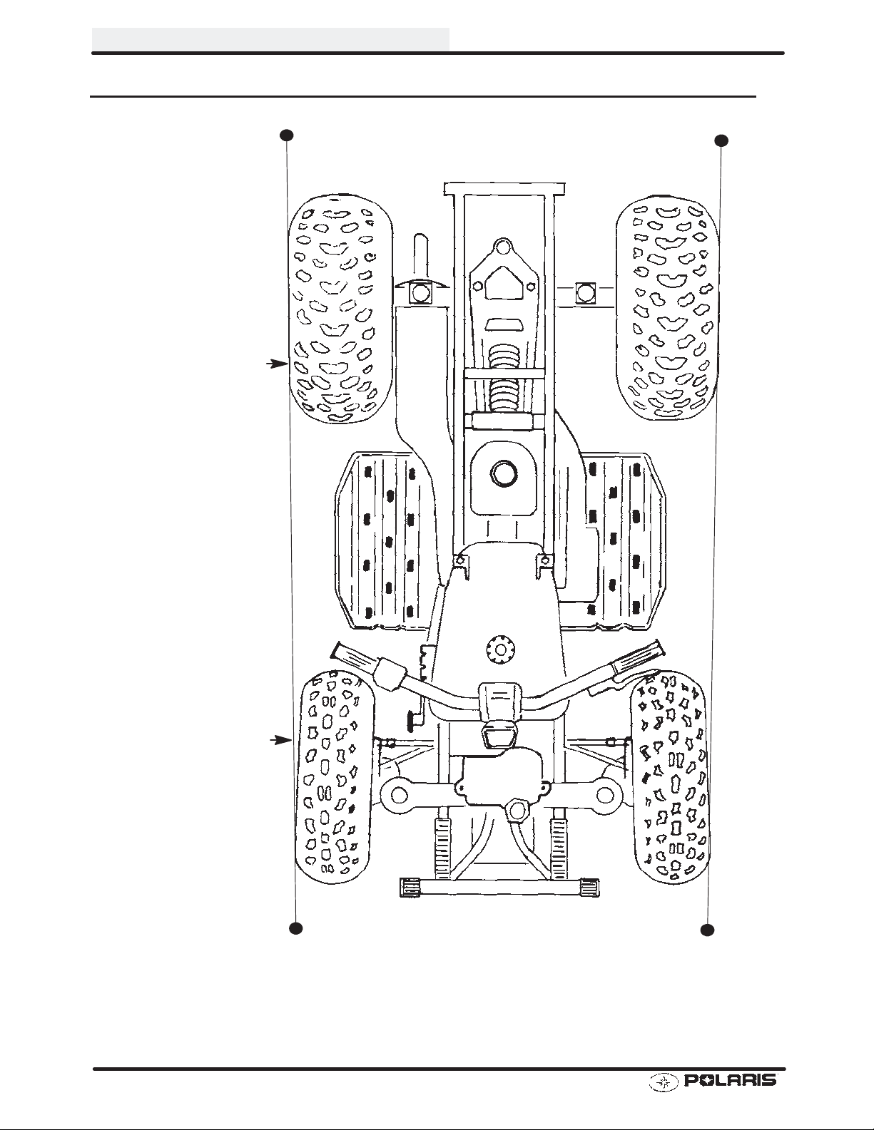
MACHINE DIMENSIONS
36.25 in
92 cm
FRONT
35.5 in
90.1 cm
45.5 in
115.6 cm
72 in
182.8 cm
1.2
SIDE
13 in
33.02 cm
9.75 in
23.5 cm
48.75 in
123.8 cm
13.5 in
34.2 cm
Page 5

MACHINE DIMENSIONS
GENERAL INFORMATION
40.6 in
103.1 cm
45.5 in
115.6 cm
REAR
Hitch
10.5 in
26.67 cm
Rock
Guard
5.5 in
13.9 cm
34.75 in
88.27 cm
44.6 in
113.3 cm
1.3
Page 6

GENERAL INFORMATION
Altitud
e
Below40
F
+40Fto+80
F
Meter
s
0-180
0
(Feet
)
above1800
Altitud
e
Below40
F
+40Fto+80
F
Meter
s
0-180
0
(Feet
)
above1800
Altitud
e
Meter
s
0-180
0
(Feet
)
180
0-370
0
MODEL: 2001 TRAIL BOSS 325..........
MODEL NUMBER: A01AA32AA.
ENGINE MODEL: ES32PFE06/07/08..
CARBURETION
Type BST 31 Mikuni................
Main Jet 145 (06/07)............
Main Jet 120 (08)............
Pilot Jet 50.............
Jet Needle 5F14--3 (06/07)...........
Jet Needle 5F14--2 (08)...........
Needle Jet P-2(829)...........
Pilot Screw 2 Turns Out..........
Pilot Air Jet 175..........
Valve Seat 1.5...........
Fuel Octane (R+M/2) 87 Non-Oxygenated or.
89 Oxygenated
JETTING CHART 06/07
Altitude
Meters
(Feet)
0-1800
(0-6000)
above 1800
(above 6000)
AMBIENT TEMPERATURE
Below 40qF
Below 5qC
150 145
142.5 137.5
JETTING CHART 08
Altitude
Meters
(Feet)
0-1800
(0-6000)
above 1800
(above 6000)
AMBIENT TEMPERATURE
Below 40qF
Below 5qC
115 120
117.5 112.5
+40_Fto+80_F
+5_Cto+26_C
+40_Fto+80_F
+5_Cto+26_C
CLUTCH
Type PVT....................
Belt 321 1077.....................
Belt Width (Projected) 1.188I (30.18mm).....
Side Angle (Overall) 26q......
Outside Circumference 40.86 r.12I....
Center Distance 10r.12I (254.5mm)..........
Clutch Offset 0.5I (12.7mm)............
Secondary Spring Black........
Driven Helix 40q.............
ENGINE
Type 4 Cycle, Single Cyl........................
Displacement 324 cc...............
Bore 3.073I (78mm).......................
Stroke 2.679I (68mm).....................
Valve Clearance In/Ex 0.006/0.006I @ BTDC on compression.......
Cooling Air w/fan assisted oil cooler....................
Lubrication Type Dry Sump............
Piston Marking None..............
Operating RPMr200 6000 RPM.........
Idle RPMr200 (lights off) 1300 RPM.....
Compression Ratio 9.2:1..........
Compression Pressure (Std) r15%.......
CLUTCH CHART
Meters
(Feet)
*40_ helix, black driven spring
0-1800
(0-6000)
1800-3700
(6000-12000)
Shift
Weight Spring Helix
10RH Blue/Green 2-2
16 Mod Blue/Green 2-2
Clutch
Driven
1.4
Page 7

GENERAL INFORMATION
MODEL: 2001 TRAIL BOSS 325............
MODEL NUMBER: A01AA32AA...
ENGINE MODEL: ES32PFE06/07/08....
ELECTRICAL FLUID Capacity Type
Flywheel I.D. None Fuel Tank 3.7 gals. (14.2L)...... ..........
CDI Marking F8T19271 Injector Oil N / A....... .......... .........
Alternator Output 200 Watts Coolant N / A... ............ .........
Ignition Timing 30qr2qBTDC@5000RPM Transmission 11.3 oz. (335 ml)PPS*..... .......
Spark Plug / Gap NGK BKR6E / 0.036I(0.9mm) Gearcase Oil (Front) N / A... .
Lights: Head Dual Beam 60/60 watts Gearcase Oil (Center) N / A......
Tail 8.26 watts Gearcase Oil (Rear) N / A........ .
Brake 26.9 watts Engine Counter Bal. N / A...... . .........
Voltage Regulator LR35 Engine Oil (06/07) 1.9 qts. (1.8L) PP4*.. ...
Electric Start Standard Engine Oil (08) 2.4 qts (2.3L) PP4*....... ...... .
Electronic Speedo N/A Brake (Hand) Dot 3.. .....................
Brake (Foot) Dot 3......................
Front Hubs (AWD) N / A...
Shift Selector Box N / A...
*PP6 Polaris Premium 60/40 Antifreeze/Coolant
*PPS Polaris Premium Synthetic Gear Case Oil
*PP4 Polaris 0W/40 Synthetic Engine Lubricant
*PDD Premium Demand Drive Hub Fluid
SUSPENSION / CHASSIS DRIVE TRAIN
Body Style Gen II Chain Type 520 O-Ring........ .........
Front Suspension MacPherson Strut Gear Reduction-Low N / A.. .
Tow Capacity 850 lbs. (385.9kg) Gear Reduction-Rev 3.05/1...... .
Turning Radius 60I (152.4cm) Gear Reduction-High 2.68/1.....
Toe Out 1/8I-1/4I (3-6.35mm) Front Drive Ratio N / A........... ....
Ground Clearance 5.5I (13.97cm) Center Drive Ratio N / A.. ...
Front Vertical Travel 6.7I (17.02cm) Final Drive Ratio 1 1/42 80P....
Rear Suspension Progressive Rate Swing Arm Brake (Hand) Single Lever, Hyd. Disc... .......
Rear Travel 9.0I (22.86cm) Brake ( Auxiliary Foot) Hydraulic........
Rear Shock 2I Gas Charged Twin Tube........
Shock Adjustment Cam..
TIRES
Tire Size - Front 23 x 7 - 10....
Tire Size - Rear 22 x 11 - 10....
Tire Size - Center N / A..
Tire Pressure - F/R 4/3 lbs..
Total Width 45.5I (115.6cm)........
Total Length 71.5I (181.61cm).......
Total Height 46I (116.84cm)........
Wheel Base 49.5I (125.73cm).......
Weight - Dry 509 lbs. (231 kgs).......
LOAD CAPACITY
Front Rack (Accy) 75 lbs.....
Rear Rack (Std) 125 lbs.......
Tongue Weight 30 lbs........
Tow Hitch Std...........
OPTIONAL SUSPENSION SPRINGS
SOFT STANDARD FIRM
Rear Compression Spring
Front Strut Spring N/A 7041850-067
7041518-067
175 lb/in.
7041518-067
175 lb/in.
41 lb/in.
7041303-067
250 lb/in.
7041375-067
64 - 113 lb/in.
1.5
Page 8

GENERAL INFORMATION
TrailB
A01A
A32A
A
PUBLICATION NUMBERS
Year Model Model No. Owner’s Manual
PN
2001
When ordering service parts be sure to use the correct parts manual.
oss 325
9915754 9916381 9916382
Parts
Manual PN
PAINT CODES
PAINTED PART COLOR
DESCRIPTION
Springs Fire Red 72060 P-093
Rims Bright White 2185 P-133
Rack(s) Fire Red 72060 P-093
Fenders, Tank & Tool
Box Covers
Bumper Caps, Front
Cover, Headlight Pod,
Seat and Side Panel
FRAME COLOR - P067 Medium Gloss Black 9440 / 8520147.
Order direct from Midwest Industrial Coatings (952-942-1840). Mix as directed.
Bright White 2185 P-133
Porsche Red N/A P-136
DITZLER
NUMBER
Parts
Micro Fiche PN
POLARIS
NUMBER
REPLACEMENT KEYS
Replacement keys can be made from the original
key. T o identify which series the key is, take the
first two digits on the original key and refer to the
chart to the right for the proper part number.
31XX
Key Series
Number
Series # Part Number
31 4110141
32 4110148
67 4010278
68 4010278
27 4010321
28 4010321
1.6
Page 9

GENERAL INFORMATION
STANDARD TORQUE SPECIFICA TIONS
The following torque specifications are to be used as a general guideline. There are exceptions in the steering,
suspension, and engine areas. Always consult the exploded views in each manual section for torque values of
fasteners before using standard torque.
Bolt Size Threads/In Grade 2 Grade 5 Grade 8
T orque in. lbs.
#10 - 24 27 (3.1) 43 (5.0) 60 (6.9).............. ................ ..............
#10 - 32 31 (3.6) 49 (5.6) 68 (7.8).............. ................ ..............
Torque ft. lbs. (Nm)
1/4 - 20 5 (7) 8 (11) 12 (16).............. .................. ................
1/4 - 28 6 (8) 10 (14) 14 (19).............. .................. ..............
5/16 - 18 11 (15) 17 (23) 25 (35).............. ................ ..............
5/16 - 24 12 (16) 19 (26) 29 (40).............. ................ ..............
3/8 - 16 20 (27) 30 (40) 45 (62).............. ................ ..............
3/8 - 24 23 (32) 35 (48) 50 (69).............. ................ ..............
7/16 - 14 30 (40) 50 (69) 70 (97).............. ................ ..............
7/16 - 20 35 (48) 55 (76) 80 (110).............. ................ ..............
1/2 - 13 50 (69) 75 (104) 110 (152).............. ................ .............
1/2 - 20 55 (76) 90 (124) 120 (166).............. ................ .............
(Nm)
*
Metric
6 x 1.0 72-78 In. lbs.
8 x 1.25 14-18 ft. lbs.
10 x 1.25 26-30 ft. lbs.
*To convert ft. lbs. to Nm multiply foot pounds by 1.382.
*To convert Nm to ft. lbs. multiply Nm by .7376.
SPECIFIC TORQUE VALUES OF FASTENERS
Refer to exploded views in the appropriate section.
1.7
Page 10

GENERAL INFORMATION
TORQUE CONVERSIONS
Newton Metre to Pound Foot and Pound Inch
1.8
Page 11

TORQUE CONVERSIONS
Newton Metre to Pound Foot and Pound Inch
GENERAL INFORMATION
1.9
Page 12

GENERAL INFORMATION
DECIMAL EQUIVALENTS
1/64 .0156.........................
1/32 .0312 1 mm = .0394s................... ................
3/64 .0469.........................
1/16 .0625..............
5/64 .0781 2 mm = .0787s......................... ................
3/32 .0938...................
7/64 .1094 3 mm = .1181s....................... ................
1/8 . .1250. .......
9/64 .1406.........................
5/32 .1563 4 mm = .1575s................... ................
11/64 .1719........................
3/16 .1875 5 mm = .1969s.............. ................
13/64 .2031........................
7/32 .2188...................
15/64 .2344 6 mm = .2362s........................ ................
1/4 .25..........
17/64 .2656 7 mm = .2756s........................ ................
9/32 .2813...................
19/64 .2969........................
5/16 .3125 8 mm = .3150s.............. ................
21/64 .3281........................
11/32 .3438 9 mm = .3543s.................. ................
23/64 .3594........................
3/8 .375..........
25/64 .3906 10 mm = .3937s........................ ................
13/32 .4063..................
27/64 .4219 1 1 mm = .4331s........................ ................
7/16 .4375..............
29/64 .4531........................
15/32 .4688 12 mm = .4724s.................. ................
31/64 .4844........................
1/2 .5 13 mm = .5118.......... ...................
33/64 .5156........................
17/32 .5313..................
35/64 .5469 14 mm = .5512s........................ ................
9/16 .5625..............
37/64 .5781 15 mm = .5906s........................ ................
19/32 .5938..................
39/64 .6094........................
5/8 .625 16 mm = .6299s.......... .................
41/64 .6406........................
21/32 .6563 17 mm = .6693s.................. ................
43/64 .6719
45/64 .7031 18 mm = .7087s........................ ................
47/64 .7344 19 mm = .7480s........................ ................
49/64 .7656........................
51/64 .7969........................
53/64 .8281........................
55/64 .8594 22 mm = .8661s........................ ................
57/64 .8906 23 mm = .9055s........................ ................
59/64 .9219.......................
61/64 .9531........................
63/64 .9844........................
.......................
11/16 .6875.............
23/32 .7188..................
3/4 .75..........
25/32 .7813 20 mm = .7874s.................. ................
13/16 .8125 21 mm = .8268s............. ................
27/32 .8438..................
7/8 .875..........
29/32 .9063..................
15/16 .9375 24 mm = .9449s............. ................
31/32 .9688 25 mm = .9843.................. ................
11.0............
1.10
Page 13

GENERAL INFORMATION
CONVERSION TABLE
Unit of Measure Multiplied by Converts to
ft. lbs. x12 =in.lbs.
in. lbs. x .0833 = ft. lbs.
ft. lbs. x 1.383 =Nm
in. lbs. x .0115 =kg-m
Nm x .7376 = ft. lbs.
kg-m x 7.233 = ft. lbs.
kg-m x 86.796 =in.lbs.
kg-m x10 =Nm
in. x 25.4 =mm
mm x .03937 =in.
in. x2.54 =cm
mile (mi.) x1.6 =km
km x .6214 = mile (mi.)
Ounces (oz) x 28.35 = Grams (g)
Fluid Ounces (fl. oz.) x 29.57 = Cubic Centimeters (cc)
Cubic Centimeters (cc) x .03381 = Fluid Ounces (fl. oz.)
Grams (g) x 0.035 = Ounces (oz)
lb. x .454 =kg
kg x 2.2046 =lb.
Cubic inches (cu in) x 16.387 = Cubic centimeters (cc)
Cubic centimeters (cc) x 0.061 = Cubic inches (cu in)
Imperial pints (Imp pt) x 0.568 = Liters (l)
Liters (l) x1.76 = Imperial pints (Imp pt)
Imperial quarts (Imp qt) x 1.137 = Liters (l)
Liters (l) x0.88 = Imperial quarts (Imp qt)
Imperial quarts (Imp qt) x 1.201 = US quarts (US qt)
US quarts (US qt) x 0.833 = Imperial quarts (Imp qt)
US quarts (US qt) x 0.946 = Liters (l)
Liters (l) x 1.057 = US quarts (US qt)
US gallons (US gal) x 3.785 =Liters (l)
Liters (l) x 0.264 = US gallons (US gal)
Pounds - force per square inch (psi) x 6.895 = Kilopascals (kPa)
Kilopascals (kPa) x 0.145 = Pounds - force per square inch (psi)
Kilopascals (kPa) x0.01 = Kilograms - force per square cm
Kilograms - force per square cm x 98.1 = Kilopascals (kPa)
S xR2x H (height) = Cylinder Volume
qCtoqF: 9 (qC + 40) y 5-40=qF
qFtoqC: 5 (qF + 40) y 9-40=qC
1.11
Page 14
GENERAL INFORMATION
SAE TAP DRILL SIZES
Thread Size Drill Size Thread Size Drill Size
#0-80 3/64
#1-64 53
#1-72 53
#2-56 51
#2-64 50
#3-48 5/64
#3-56 45
#4-40 43
#4-48 42
#5-40 38
#5-44 37
#6-32 36
#6-40 33
#8-32 29
#8-36 29
#10-24 24
#10-32 21
#12-24 17
#12-28 4.6mm
1/4-20 7
1/4-28 3
5/16-18 F
5/16-24 I
3/8-16 O
3/8-24 Q
7/16-14 U
7/16-20 25/64
1/2-13 27/64
1/2-20 29/64
9/16-12 31/64
9/16-18 33/64
5/8-11 17/32
5/8-18 37/64
3/4-10 21/32
3/4-16 1 1/16
7/8-9 49/64
7/8-14 13/16
1-8 7/8
1-12 59/64
1 1/8-7 63/64
1 1/8-12 1 3/64
11/4-7 17/64
1 1/4-12 1 11/64
11/2-6 111/32
1 1/2-12 1 27/64
13/4-5 19/16
1 3/4-12 1 43/64
2-4 1/2 1 25/32
2-12 1 59/64
2 1/4-4 1/2 2 1/32
21/2-4 21/4
23/4-4 21/2
3-4 2 3/4
METRIC TAP DRILL SIZES
Tap S i z e Drill Size Decimal Equivalent Nearest Fraction
3x.50
3x.60
4x.70
4x.75
5x.80
5x.90
6 x 1.00
7 x 1.00
8 x 1.00
8 x 1.25
9 x 1.00
9 x 1.25
10 x 1.25
10 x 1.50
11 x 1. 5 0
12 x 1.50
12 x 1.75
#39
3/32
#30
1/8
#19
#20
#9
16/64
J
17/64
5/16
5/16
11/32
R
3/8
13/32
13/32
0.0995
0.0937
0.1285
0.125
0.166
0.161
0.196
0.234
0.277
0.265
0.3125
0.3125
0.3437
0.339
0.375
0.406
0.406
3/32
3/32
1/8
1/8
11/64
5/32
13/64
15/64
9/32
17/64
5/16
5/16
11/32
11/32
3/8
13/32
13/32
1.12
Page 15

GENERAL INFORMATION
GLOSSARY OF TERMS
ABDC: After bottom dead center.
ACV: Alternating current voltage.
Alternator: Electrical generator producing voltage alternating current.
ATDC: After top dead center.
BBDC: Before bottom dead center.
BDC: Bottom dead center.
BTDC: Before top dead center.
CC: Cubic centimeters.
Center Distance: Distance between center of crankshaft and center of driven clutch shaft.
Chain Pitch: Distance between chain link pins (No. 35 = 3/8s or 1 cm). Polaris measures chain length in number of
pitches.
CI: Cubic inches.
Clutch Buttons: Plastic bushings which transmit rotation of the clutch to the movable sheave in the drive and driven
clutch.
Clutch Offset: Drive and driven clutches are offset so that drive belt will stay nearly straight as it moves along the clutch
face.
Clutch Weights: Three levers in the drive clutch which relative to their weight, profile and engine RPM cause the drive
clutch to close.
Condenser/Capacitor: A storage reservoir for DC voltage.
Crankshaft Run-Out: Run-out or “bend” of crankshaft measured with a dial indicator while crankshaft is supported
between centers on V blocks or resting in crankcase. Measure at various points especially at PTO.
DCV: Direct current voltage.
Dial Bore Gauge: A cylinder measuring instrument which uses a dial indicator. Good for showing taper and
out-of-round in the cylinder bore.
Electrical Open: Open circuit. An electrical circuit which isn’t complete.
Electrical Short: Short circuit. An electrical circuit which is completed before the current reaches the intended load.
(i.e. a bare wire touching the chassis).
End Seals: Rubber seals at each end of the crankshaft.
Engagement RPM: Engine RPM at which the drive clutch engages to make contact with the drive belt.
ft.: Foot/feet.
Foot Pound: Ft. lb. A force of one pound at the end of a lever one foot in length, applied in a rotational direction.
g: Gram. Unit of weight in the metric system.
gal.: Gallon.
HP: Horsepower.
ID: Inside diameter.
in.: Inch/inches.
Inch Pound: In. lb. 12 in. lbs. = 1 ft. lb.
kg/cm
kg-m: Kilogram meters.
Kilogram/meter: A force of one kilogram at the end of a lever one meter in length, applied in a rotational direction.
lorltr: Liter.
lbs/in
Left Side: Always referred to based on normal operating position of the driver.
2
: Kilograms per square centimeter.
2
: Pounds per square inch.
1.13
Page 16

GENERAL INFORMATION
GLOSSARY OF TERMS
m: Meter/meters.
Mag: Magneto.
Magnetic Induction: As a conductor (coil) is moved through a magnetic field, a voltage will be generated in the
windings. Mechanical energy is converted to electrical energy in the stator.
mi.: Mile/miles.
mm: Millimeter. Unit of length in the metric system. 1mm = approximately .040s.
Nm: Newton meters.
OD: Outside diameter.
Ohm: The unit of electrical resistance opposing current flow.
oz.: Ounce/ounces.
Piston Clearance: Total distance between piston and cylinder wall.
psi.: Pounds per square inch.
PTO: Power take off.
PVT: Polaris Variable Transmission (Drive Clutch System)
qt.: Quart/quarts.
RPM: Revolutions per minute.
Regulator: Voltage regulator. Regulates battery charging system output at approx. 14.5 DCV as engine RPM
increases.
Reservoir Tank: The fill tank in the liquid cooling system.
Resistance: In the mechanical sense, friction or load. In the electrical sense, ohms. Both result in energy conversion to
heat.
Right Side: Always referred to based on normal operating position of the driver.
RPM: Revolutions per minute.
Secondary Clutch: Driven clutch on chaincase or jackshaft.
SeizedPiston: Galling of the sides of a piston. Usually there is a transfer of aluminum from the piston onto the cylinder
wall. Possible causes: 1) improper lubrication; 2) excessive temperatures; 3) insufficient piston clearance; 4) stuck
piston rings.
Stator Plate: The plate mounted under the flywheel supporting the battery charging coils.
TDC: Top dead center. Piston’s most outward travel from crankshaft.
Vol t: The unit of measure for electrical pressure of electromotive force. Measured by a voltmeter in parallel with the
circuit.
Watt: Unit of electrical power. Watts = amperes x volts.
WOT: Wide open throttle.
1.14
Page 17

CHAPTER 2
MAINTENANCE
Periodic Maintenance Chart 2.1-2.2....................
Pre-Ride Inspection 2.2...........................
Recommended Lubricants 2.3.....................
Lubricant and Maintenance Product Numbers 2.4....
Lubrication Charts 2.5-2.6............................
Transmission Lubrication 2.7......................
Torque Stop Adjustment 2.7.......................
Transmission Linkage Inspection 2.8...............
Carburetor Adjustments 2.8-2.11.......................
Fuel System 2.12-2.13.................................
Compression Test 2.14............................
Battery Maintenance 2.15..........................
Electrical 2.16....................................
Air Filter Service 2.17..............................
Air Box Sediment Tube Service 2.17.................
Recoil Housing 2.18...............................
Oil Change/Filter 2.19-2.20.............................
Valve Clearance 2.21-2.22..............................
Steering and Toe Allignment 2.23-2.25...................
Exhaust System Service 2.26.......................
Brake System Service 2.27-2.28.........................
Drive Chain Service 2.29-2.32...........................
Suspension Service 2.33...........................
Wheel Removal/Installation 2.34....................
Tire Inspection 2.35...............................
2
Page 18

Page 19

MAINTENANCE
PERIODIC MAINTENANCE CHART
Inspection, adjustment and lubrication intervals of important components is listed in the following chart.
Maintenance intervals are based upon average riding conditions and a vehicle speed of approximately 10 mph.
Inspect, clean, lubricate, adjust or replace parts as necessary. More frequent maintenance is required if vehicle
is used for utility work at speeds averaging less than 10 mph. NOTE: Inspection may reveal the need for replacement parts. Always use genuine Polaris parts.
HCAUTION: Due to the nature of these adjustments, it is recommended that service be performed by an
authorized Polaris dealer.
"Vehicles subjected to severe use (operation in wet or dusty areas, low speed heavy load operation, prolonged
idle) should be inspected and serviced more frequently. For engine oil, short trip cold weather riding also constitutes severe use. Pay special attention to oil level. Change oil immediately if oil level begins to rise.
E Emission Control System Service (California).
PERIODIC MAINTENANCE - ENGINE
Frequency
(Whichever comes first)
Item Hours Calendar Miles
(Km)
Engine Oil - Level/Change 100 hrs 6 months 1000 (1600) Check Level Daily; Break In service at 1 month
E"
Oil Filter 100 hrs 6 months 1000 (1600) Replace with oil change
E
Air Filter - Foam Pre-Cleaner Daily Daily Inspect-Clean & oil more often in dirty conditions.
E"
Air Filter - Main Element Weekly Weekly Inspect - Replace if necessary
E"
" Air Box Sediment Tube - Daily Drain deposits whenever visible
Valve Clearance 100 hrs 12 months 1000 (1600) Inspect/Adjust
EH
Idle Speed As required As required Adjust
E
H Throttle Cable / ETC Switch 50 hrs 6 months 500 (800) Inspect -Adjust, Lubricate, Replace if necessary
Choke (Enricher) Cable 50 hrs 6 months 500 (800) Inspect -Adjust, Lubricate, Replace if necessary
Carburetor Float Bowl 50 hrs 6 months 500 (800) Drain bowl periodically and prior to storage
Carburetor Air Intake Ducts/Flange 50 hrs 6 months 500 (800) Inspect all ducts for proper sealing/air leaks
Fuel System 100 hrs 12 months 1000 (1600) Check for leaks at tank cap, lines, fuel valve, filter,
EH
Fuel Filter 100 hrs 12 months 1000 (1600) Replace filter annually
EH
Radiator/Oil Cooler 100 hrs 12 months 1000 (1600) Inspect / Clean external surface
Engine Mounts 100 hrs 12 months 1000 (1600) Inspect
Drain Recoil Housing Weekly Weekly More often if operating in wet environment
Exhaust Muffler / Pipe 100 hrs 12 months 1000 (1600)
pump & carburetor. Replace lines every 2 years.
ELECTRICAL
Spark Plug 100 hrs 12 months 1000 (1600) Inspect - Replace if necessary
E
Wiring 100 hrs 12 months 1000 (1600) Inspect for abrasion, routing, security
Ignition Timing 100 hrs 12 months 1000 (1600) Inspect
Battery 20 hrs Monthly 200 (320) Check terminals; Clean; Check fluid level
Headlight Aim As required As required Adjust if Necessary
Headlamp Inspection Daily Daily Check operation daily; Apply Polaris Dielectric
Tail Lamp Inspection Daily Daily Check Operation Daily; Apply Polaris Dielectric
Grease to connector when lamp is replaced
Grease to socket when lamp is replaced
Remarks
2.1
Page 20

MAINTENANCE
PERIODIC MAINTENANCE CHART, CONT.
CHASSIS
Frequency
(Whichever comes first)
Item Hours Calendar Miles
(Km)
" General Lubrication 50 hrs 3 months 500 (800) Lubricate All Fittings, Pivots, Cables, Etc.
H Front Wheel Bearings Annually 12 months Inspect and replace if necessary
Drive Belt 50 hrs 6 months 500 (800) Inspect - Adjust, Replace if Necessary
Clutches (Drive And Driven) 100 hrs 12 months 1000 (1600) Inspect, Clean
" Transmission Oil Level 25 hrs Monthly 250 (400) Inspect Monthly; Change Annually
Shift Linkage 50 hrs 6 months 500 (800) Inspect,Lubricate, Adjust
H Steering 50 hrs 6 months 500 (800) Inspect Daily, Lubricate
H Toe Adjustment As required As required Periodic Inspection, Adjust When Parts are Re-
placed
" Rear Axle 50 hrs 6 months 500 (800) Inspect Bearings, Grease Fitting
" Front Suspension 50 hrs 6 months 500 (800) Inspect - Lubricate
" Rear Suspension 50 hrs 6 months 500 (800) Inspect - Lubricate
Drive Chain 50 hrs 6 months 500 (800) Inspect Daily, Adjust and Lubricate if Needed
Tires Pre-ride Pre-ride Inspect Daily, Pre-Ride Inspection Item
H Brake Fluid 200 hrs 24 months 2000 (3200) Change Every Two Years
" Brake Fluid Level Pre-ride Pre-ride Inspect Daily, Pre-Ride Inspection Item
" Brake Lever/Pedal T ravel Pre-ride Pre-ride Inspect Daily, Pre-Ride Inspection Item
H Brake Pad Wear 10 hrs Monthly 100 (160) Inspect Periodically
Brake System Pre-ride Pre-ride Pre-Ride Inspection Item
Wheels Pre-ride Pre-ride Pre-Ride Inspection Item
Frame Nuts, Bolts, Fasteners Pre-ride Pre-ride Pre-Ride Inspection Item
Remarks
PRE-RIDE / DAILY INSPECTION
Perform the following pre-ride inspection daily, and when servicing the vehicle at each scheduled maintenance.
S Tires - check condition and pressures
S Fuel and engine oil level
S All brakes - check operation and adjustment (includes auxiliary brake)
S Throttle - check for free operation and closing
S Headlight/Taillight/Brakelight - check operation of all indicator lights and switches
S Engine stop switch - check for proper function
S Wheels - check for tightness of wheel nuts and axle nuts; check to be sure axle nuts are se-
cured by cotter pins
S Drive chain - condition and slack; refer to drive chain adjustment
S Inspect vehicle for any visible signs of oil leakage
S Air cleaner element - check for dirt; clean or replace
S Steering - check for free operation noting any unusual looseness in any area
S Loose parts - visually inspect vehicle for any damaged or loose nuts, bolts or fasteners
2.2
Page 21

MAINTENANCE
RECOMMENDED LUBRICANTS - QUICK REFERENCE
LUBRICANTS AND MAINTENANCE PRODUCT PART NUMBERS ARE LISTED ON PAGE 2.4. REFER
TO SPECIFICATIONS CHAPTER 1 FOR CAPACITY INFORMA
Item
Engine Oil Polaris Premium 4
Synthetic, 0W/40
Transmission Polaris Synthetic Gear
Case Lubricant
Brake Fluid Polaris DOT 3 Brake Fluid Fill to indicated level inside reservoir. 2.29
Typ e Notes See
Add to proper level on dipstick. 2.21
Refer to procedures outlined later in this
chapter.
TION.
Page
2.7
COLD WEATHER KITS FOR 4 STROKE ATVS
Engine Heater -- PN 2871507
2.3
Page 22

MAINTENANCE
POLARIS PREMIUM LUBRICANT AND MAINTENANCE PRODUCT PART
Part No. Description
2870791 Fogging Oil
2871281 Engine Oil (Quart) Premium 4 Synthetic 0-W40 (4-Cycle)
2871567 Engine Oil (16 Gallon) Premium 4 Synthetic 0-W40 (4-Cycle)
2871477 Premium Synthetic Gearcase Lubricant (1 Gal.)
2871478 Premium Synthetic Gearcase Lubricant (12 oz.. bottle)
2870465 Oil Pump for Gearcase Oil
2871322 Premium All Season Grease (3 oz.. cartridge)
2871423 Premium All Season Grease (14 oz.. cartridge)
2871460 Starter Drive Grease
2871312 Grease Gun Kit
2871329 Dielectric Grease (Nyogelt)
2870585 Loctitet Primer N, Aerosol, 25g
2871949 Loctitet Threadlock 242 (50ml.)
2871950 Loctitet Threadlock 242 (6ml.)
2871951 Loctitet Threadlock 262 (50ml.)
2871952 Loctitet Threadlock 262 (6ml.)
2871953 Loctitet Threadlock 271 (6ml.)
2871954 Loctitet Threadlock 271 (36ml.)
2870584 Loctitet RC 680-Retaining Compound (10ml. )
2870587 Loctitet 518 Gasket Eliminator / Flange Sealant (50ml.)
2871326 Premium Carbon Clean 12 oz..
2870652 Fuel Stabilizer 16 oz..
2871957 Black RTV Silicone Sealer (3 oz.. tube)
2871958 Black RTV Silicone Sealer (11 oz.. cartridge)
8560054 Marine Grade Silicone Sealer (14 oz.. cartridge)
2870990 DOT3 Brake Fluid
2872113 Disc Brake Quiet, Aerosol, (9 oz..)
2871557 Crankcase Sealant, 3-Bond 1215
NUMBERS
Engine Lubricant
Gearcase / Transmission Lubricants
Grease / Specialized Lubricants
Additives / Sealants / Thread Locking Agents / Misc.
2.4
Page 23

LUBRICATION
Apply
4DriveChainPolarisChain
Applytochainlinkplatesandroll
Asrequire
d
ubeoO
g
e
s
MAINTENANCE
Ill.
Item Lube Rec. Method Frequency*
#
1 Engine Oil Polaris 0W/40
Synthetic
2 Transmission Polaris Synthet-
ic Gear Case
Lubricant
3 Brake Fluid Polaris DOT 3
Brake Fluid
4 Drive Chain Polaris Chain
Lube or O-Ring
chain lube
Dipstick
Add oil to proper level. Change after 1st month, 6 months or 100
hours thereafter; Change more often (25-50
hours) in extremely dirty conditions, or short
trip cold weather operation.
Add lube to full level on dipstick Change annually
Fill master cylinder reservoir to indicated level inside reservoir. See
page 2.29 .
to chain linkplates and roll-Asrequired
ers
As required. Change fluid every 2 years.
Transmission
Dipstick
Full
1. Engine Oil
Parking Brake Lock
3. Brake Fluid
2. Transmission
4. Rear Drive Chain
Operating Range
2.5
Page 24

MAINTENANCE
LUBRICATION
9. Steering Post
10. Rear Axle Bearings
8. Tie Rod End
11. Swing A rm
D
5. Front
Wheel
Bearings
Bushings
7. Front A-Arm
Pivot Shaft
Ill.
#
5 Front Wheel Bear-
ings
6 Ball Joint Polaris All Season
7 Front A-Arm Pivot
Shaft
8 Tie Rod Ends Polaris All Season
9 Steering Post Bush-
ings
10 Rear Axle Bearings Polaris All Season
11 Swing Arm Bush-
ings
Item Lube Rec. Method Frequency*
Sealed; Replace Inspect and replace bearings if necessary Annually ©
Grease¢
Polaris All Season
Grease¢
Grease¢
All Season
Grease¢
Grease¢
Polaris All Season
Grease¢
6. Ball Joint
Locate grease fitting on back side of struts and
grease with grease gun.
Locate grease fitting on pivot shaft and grease with
grease gun.
Lift boot. Clean away dirt and grease. Apply fresh
grease by hand and reassemble.
Locate fittings on upper and lower steering post and
grease with grease gun.
Locate grease fitting on eccentric and grease with
grease gun.
Locate grease fitting on swing arm and grease with
grease gun.
Semi-annually
¡
Semi-annually
¡
Semi-annually
¡
Semi-annually
¡
Semi-annually
¡
Semi-annually
¡
* More often under severe use, such as operated in water or under severe loads.
¡ Semi-annually or 50 hours of operation (refer to Maintenance Schedule for additional information)
© Annually or 100 hours of operation (refer to Maintenance Schedule for additional information)
¢ Grease conforming to NLGI No. 2, such as Polaris Premium All Season Grease, Conoco Superlube M or
Mobilegrease Special
2.6
Page 25

MAINTENANCE
TRANSMISSION LUBRICATION
The transmission lubricant level should be checked and changed in accordance with the maintenance schedule.
S Be sure vehicle is level before proceeding.
S Check vent hose to be sure it is routed properly and unobstructed.
S Follow instructions on following pages to check / change transmission lubricant.
TRANSMISSION SPECIFICATIONS
Specified Lubricant:
Polaris Premium Synthetic Gearcase Lubricant
PN 2871477 (Gallon) PN 2871478 (12 oz..)
Capacity:
Drain Plug / Fill Plug Torque:
14 ft. lbs. (19.4 Nm)
1 1.3 oz. (335 ml)....
TRANSMISSION LEVEL CHECK/CHANGE
To check the level:
1. Remove dipstick and wipe clean.
2. Reinstall dipstick completely, remove and check the
level. Add the proper lubricant as required to bring
level into operating range as shown.
TRANSMISSION FLUID
CHANGE/TORQUE STOP
AD-
JUSTMENT
1. Remove skid plate (if necessary).
2. Place a drain pan beneath the transmission oil drain
plug area.
3. Loosen jam nut (A).
4. Turn adjuster bolt (B) in to allow the removal of drain
plug.
5. Remove the drain plug and wipe the magnetic end
clean to remove accumulated metallic filings.
6. After the oil has drained completely, install a new
sealing washer and install the drain plug. T orque to
14 ft. lbs. (19.3 Nm).
7. Turn adjuster bolt (B) out until it touches the frame,
and then an additional 1/2 turn.
8. Tighten the jam nut securely while holding the
adjuster bolt.
9. Add the proper lubricant through the dipstick hole
until the oil level is between the upper and lower
limits. Do not overfill.
10. Check for leaks.
11. Reinstallskidplateifremovedinstep1.
Forward
Full
PVT Cover
A
Transmission
Dipstick
Operating
Range
Drain Plug
B
2.7
Page 26

MAINTENANCE
TRANSMISSION GEARSHIFT LINKAGE ADJUSTMENT,
PRELIMINARY
S If shifting problems are encountered, the transmis-
sion linkage should be adjusted.
S Tighten shift linkage rod end jam nuts properly after
adjustment. You should be able to rotate the linkage
rod between 1/8 and 1/4 turn after both jam nuts are
tight. Clevis or rod end should be parallel to mounting
surface.
S The transmission shift linkage should be periodically
inspected for wear and parts replaced as required to
remove excess play from shift linkage.
S Refer to Transmission chapter for more information.
INSPECTION
CHOKE (ENRICHER) ADJUSTMENT
With the choke control pushed in, the choke plunger must
be seated on the fuel passage way in the carburetor. If the
plunger is not seated on the fuel passage way inside the
carburetor (not enough cable freeplay), the engine will flood
or run too rich, causing plug fouling and poor performance.
Linkage rod will rotate
1/8 -1/4 turn if rod ends
are tightened properly.
Correctly Tightened
Jam Nut
Parallel
Incorrectly Tightened
Jam Nut
If cable slack is excessive, the choke fuel passage will not
open far enough, which may cause cold starting difficulty.
Also, the half-choke position used for intermittent applications will not function properly.
1. Locate the boot behind the choke knob and pull it back.
Loosen the friction nut 1 turn or until choke slides freely.
Re-install boot.
2. Push the choke knob in to the full off position.
3. Slide boots off in-line cable adjuster and loosen
adjustment locknut.
4. Turn adjuster until the choke knob pulls out over 1/4s.
5. Push on the choke knob lightly while turning the
adjuster the opposite way.
6. Turn the adjuster until the knob contacts the boot.
7. Tighten adjuster nut.
8. Slide boots back over cable adjuster sleeve until they
touch at the middle point of the adjuster.
9. Pull back the choke knob boot and tighten the friction
nut until the choke will maintain a set position.
Re-install boot.
Boot
Adjuster
Sleeve
Locknut
Boot
2.8
Page 27

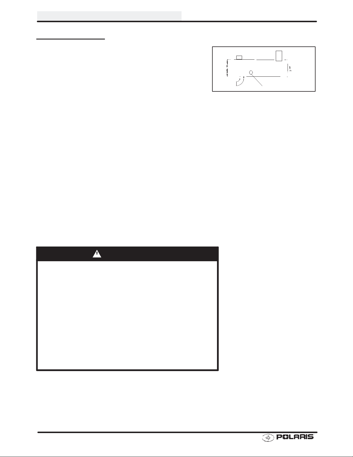
IDLE SPEED ADJUSTMENT
MAINTENANCE
1. Start engine and warm it up thoroughly.
2. Adjust idle speed by turning the idle adjustment screw
in (clockwise) to increase or out (counterclockwise) to
decrease RPM. (Refer to Ill. at right).
NOTE: Adjusting the idle speed affects throttle cable
freeplay and electronic throttle control (ETC) adjustment.
Always check throttle cable freeplay after adjusting idle
speed and adjust if necessary.
Idle Speed:
1300 RPM r 200
CV Carburetor
Idle Screw
PILOT SCREW (IDLE MIXTURE) ADJUSTMENT NOTES
Do not tighten the pilot screw forcefully against the seat or the screw and/or seat will be permanently dam-
aged.
Start engine and warm it up to operating temperature (about 10 minutes). This is a very important step.
PILOT SCREW ADJUSTMENT
IMPORTANT NOTE: Idle speed is specified with the lights OFF. On the idle speed will drop between 100-150 RPM
when the lights are turned on.
1. Connect an accurate tachometer such as the PET
2100DX (P/N 8712100DX) or the PET 2500 (P/N
8712500).
2. Adjust idle speed using the idle speed screw to about
1600 RPM.
3. Turn the pilot screw (mixture screw) in or out slowly
using the pilot screw wrench to obtain the highest idle
RPM.
4. Re-adjust idle speed to specified RPM (1300 r100).
5. Again turn the pilot screw in or out slowly to obtain the
highest idle RPM.
6. Turn the pilot screw out (counterclockwise) 1/8 to 1/4
turn.
7. Re-adjust idle speed to specified RPM (1300 r100).
FRONT
(Engine)
Pilot Screw
2.9
Page 28

MAINTENANCE
THROTTLE CABLE FREEPLAY/ ELECTRONIC THROTTLE
CONTROL (ETC SWITCH)
Check for smooth throttle opening and closing in all handlebar positions. Throttle lever operation should be
smooth and lever must return freely without binding.
1. Slide boot off throttle cable adjuster and jam nut.
2. Place shift selector in neutral and set parking brake.
3. Start engine and set idle to specified RPM.
NOTE: Be sure the engine is at operating temperature.
See Idle Speed Adjustment.
4. Loosen lock nut on in-line cable adjuster (Ill. 1).
5. Turn cable adjuster out until engine RPM begins to
increase.
6. Turn cable adjuster back in until throttle lever has
1/16s (.16 cm) of travel before engine RPM increases
(Ill. 2).
7. Tightenlock nut securely and slide boot completely in
place to ensure a water-tight seal.
ADJUSTMENT
Ill. 1
Boot
Adjuster
Sleeve
Locknut
Throttle Cable
Adjuster
Lock Nut
Boot
Ill. 2
Ill. 3
Direction
of travel
1/16s -1/8s
Freeplay
2.10
Page 29

MAINTENANCE
THROTTLE CABLE FREEPLAY/ ELECTRONIC THROTTLE
CONTROL (ETC SWITCH) ADJUSTMENT, CONT
8. Turn handlebars from left to right through the entire
turning range. If idle speed increases, check for
proper cable routing. If cable is routed properly and
in good condition, repeat adjustment procedure.
ETC switch contacts are closed
in fault condition
(throttle cable
slack).
.
Switch contacts are open
during normal operation
A
2.11
Page 30

MAINTENANCE
FUEL SYSTEM
WARNING
Gasoline is extremely flammable and explosive under certain conditions.
Always stop the engine and refuel outdoors or in a well ventilated area.
Do not smoke or allow open flames or sparks in or near the area where refueling is performed or where
gasoline is stored.
Do not overfill the tank. Do not fill the tank neck.
If you get gasoline in your eyes or if you swallow gasoline, see your doctor immediately.
If you spill gasoline on your skin or clothing, immediately wash it off with soap and water and change clothing.
Never start the engine or let it run in an enclosed area. Gasoline powered engine exhaust fumes are poisonous and can cause loss of consciousness and death in a short time.
Never drain the float bowl when the engine is hot. Severe burns may result.
FUEL LINES
1. Check fuel lines for signs of wear, deterioration,
damage or leakage. Replace if necessary.
2. Be sure fuel lines are routed properly and secured with
cable ties. CAUTION: Make sure lines are not kinked
or pinched.
3. Replace all fuel lines every two years.
VENT LINES
1. Check fuel tank, oil tank, carburetor, battery and
transmission vent lines for signs of wear,deterioration,
damage or leakage. Replace every two years.
2. Be sure vent lines are routed properly and secured
with cable ties. CAUTION: Make sure lines are not
kinked or pinched.
FUEL FILTER
The fuel filter should be replaced in accordance with the
Periodic Maintenance Chart or whenever sediment is visible in the filter.
1. Shut off fuel supply at fuel valve.
2. Remove line clamps at both ends of the filter.
3. Remove fuel lines from filter.
4. Install new filter and clamps onto fuel lines with arrow
pointed in direction of fuel flow.
5. Install clamps on fuel line.
6. Turn fuel valve ON.
7. Start engine and inspect for leaks.
8. Reinstall fuel tank.
Arrow Indicates Direction
of Flow
To Carburetor
2.12
Page 31

CARBURETOR DRAINING
The carburetor float bowl should be drained periodically to
remove moisture or sediment from the bowl, or before extended periods of storage.
NOTE: The bowl drain screw is located on the bottom left
side of the float bowl.
MAINTENANCE
1. Turn fuel valve to the off position.
2. Place a clean container beneath the bowl drain spigot
or bowl drain hose.
3. Turn drain screw out two turns and allow fuel in the
float bowl and fuel line to drain completely.
4. Inspect the drained fuel for water or sediment.
5. Tighten drain screw securely.
6. Turn fuel valve to “on”.
7. Start machine and check for leaks.
8. Replace vent line if removed.
Drain tube
attached
here
Drain Screw
RES
OFF
ON
Fuel Valve
2.13
Page 32

MAINTENANCE
COMPRESSION TEST
NOTE: 4-Stroke engines are equipped with an automatic decompressor. Compression readings will vary in pro-
portion to cranking speed during the test. Average compression (measured) is about 50-90 psi during a compression test.
Smooth idle generally indicates good compression. Low enginecompression is rarely a factor in running condition
problems above idle speed. Abnormally high compression can be caused by a decompressor malfunction, or
worn or damaged exhaust cam lobes. Inspect camshaft and automatic decompression mechanism if compression is abnormally high.
A cylinder leakage test is the best indication of engine condition on models with automatic decompression. Follow
manufacturer’s instructions to perform a cylinder leakage test. (Never use high pressure leak tester as crankshaft
seals may dislodge and leak).
Cylinder Leakage
Service Limit: 10 %
(Inspect for cause if leakage exceeds 10%)
ENGINE MOUNTS
Inspect rubber engine mounts (A) for cracks or damage.
FASTENER TORQUE - ENGINE
Check engine fasteners and ensure they are tight.
A
A
2.14
Page 33

BATTERY MAINTENANCE
WARNING
Battery electrolyte is poisonous. It contains sulfuric acid. Serious
burns can result from contact with skin, eyes or clothing. Antidote:
External: Flush with water.
Internal: Drink large quantities of water or milk. Follow with milk
of magnesia, beaten egg, or vegetable oil. Call physician immediately.
Eyes: Flush with water for 15 minutes and get prompt medical
attention.
Batteries produce explosive gases. Keep sparks, flame, cigarettes, etc. away. Ventilate when charging or using in an enclosed
space. Always shield eyes when working near batteries. KEEP
OUT OF REACH OF CHILDREN.
The battery is located under the left rear fender.
MAINTENANCE
Inspect the battery fluid level. When the battery fluid nears
the lower level, the battery should be removed and distilled
water should be added to the upper level line. To remove
the battery:
1. Disconnect holder strap and remove cover.
2. Disconnect battery negative (-) (black) cable first,
followed by the positive (+) (red) cable.
CAUTION
Whenever removing or reinstalling the battery , disconnect
the negative (black) cable first and reinstall the negative
cable last!
3. Disconnect the vent hose.
4. Remove the battery.
5. Remove the filler caps and add distilled water only as needed to bring each cell to the proper level. Do not
overfill the battery.
To refill use only distilled water. T ap water contains minerals which are harmful to a battery.
Do not allow cleaning solution or tap water to enter the battery. It will shorten the life of the battery.
6. Reinstall the battery caps.
7. Clean battery cables and terminals with a stiff wire brush. Corrosion can be removed using a solution of one
cup water and one tablespoon baking soda. Rinse well with clean water and dry thoroughly.
8. Reinstall battery, attaching positive (+) (red) cable first and then the negative (-) (black) cable.
9. Reattach vent hose making sure it is properly routed and not kinked or pinched.
10. Coat terminals and bolt threads with Polaris dielectric grease.
1 1. Reinstall battery cover and holder strap.
Maintain
between upper
and lower level
marks
NOTE: New Battery:
of batterys’ full potential.
Battery must be fully charged before use or battery life will be significantly reduced 10-30%
2.15
Page 34

MAINTENANCE
SPARK PLUG
1. Remove spark plug high tension lead. Clean plug area
so no dirt and debris can fall into engine when plug is
removed.
2. Remove spark plug.
3. Inspect electrodes for wear and carbon buildup. Look
for a sharp outer edge with no rounding or erosion of
the electrodes.
4. Clean with electrical contact cleaner or a glass bead
spark plug cleaner only. CAUTION: A wire brush or
coated abrasive should not be used.
5. Measure gap with a wire gauge. Refer to
specifications for proper spark plug type and gap.
Adjust gap if necessary by bending the side electrode
carefully.
6. If necessary, replace spark plug with proper type.
CAUTION: Severe engine damage may occur if the
incorrect spark plug is used.
7. Apply a small amount of anti-seize compound to the
spark plug threads.
8. Install spark plug and torque to 14 ft. lbs.
IGNITION TIMING
Recommended Spark Plug:
Refer to Specifications
Spark Plug Torque: 14 Ft. Lbs.
(19 Nm)
Spark Plug Gap
.032 - .036s¢.8 - .9 mm)
Refer to Electrical chapter for ignition timing procedure.
ENGINE-TO-FRAME GROUND
Inspect engine-to-frame ground cable connection. Be
sure it is clean and tight.
Engine Ground Strap
2.16
Page 35

PREFILTERANDAIRFILTERSERVICE
1. Remove seat.
2. Remove spring clamps securing the airbox lid and
remove lid.
3. Pull foam breather filter out.
4. Loosen clamp and remove filter.
5. Remove foam or mesh pre-filter from main filter.
6. Carefully wash the pre-filter in soapy water and dry
it thoroughly. Replace the pre-filter if the element is
torn or damaged.
7. Install dry pre-filter over new main filter and
reinstall.
Mesh
Pre-filter
AIR BOX SEDIMENT TUBE
Periodically check the air box drain tube located toward the
rear of the machine. Drain whenever deposits are visible
in the clear tube.
MAINTENANCE
Main Filter
NOTE: The sediment tube will require more frequent service if the vehicle is operated in wet conditions or at high
throttle openings for extended periods.
1. Remove drain plug from end of sediment tube.
2. Drain tube.
3. Reinstall drain plug.
BREATHER HOSE
1. Be sure breather line is routed properly and secured in
place. CAUTION: Make sure lines are not kinked or
pinched.
Sediment Tube
2.17
Page 36

MAINTENANCE
RECOIL HOUSING
S Drain the housing periodically to remove moisture.
S Drain the recoil housing after operating the ATV in
very wet conditions. This should also be done before
storing the ATV. The drain screw is located at the bottom of the recoil housing. Remove the screw with a
10mm wrench. Reinstall screw once housing has
been drained.
S CAUTION: Make sure the manual start handle is ful-
ly seated on the recoil housing, especially when travelling in wet areas. If it is not sealed properly, water
may enter the recoil housing and damage components.
S Water will enter the recoil housing if the starter handle
is disengaged from the rope guide when under water.
S After travelling in wet areas the recoil housing and
starter should always be drained completely by removing the recoil.
S Do not open the crankcase drain unless the engine
has ingested water.
Crankcase Drain
Recoil Drain (above front
propshaft)
2.18
Page 37

ENGINE OIL LEVEL
To check the oil level:
1. Set machine on a level surface.
2. Start and run engine for 20-30 seconds. This will return
oil to its true level in the engine sump..
3. Stop engine, remove dipstick and wipe dry with a clean
cloth.
4. Reinstall dipstick, screwing into place.
NOTE: The dipstick must be screwed completely in to ensure accurate measurement.
5. Remove dipstick and check to see that the oil level is in
the normal range. Add oil as indicated by the level on
the dipstick. Do not overfill.
NOTE: Rising oil level between checks in cool weather
driving, can indicate moisture collecting in the oil reservoir.
If the oil level is over the full mark, change the oil.
OIL AND FILTER CHANGE
MAINTENANCE
1. Place vehicle on a level surface.
2. Run engine two to three minutes until warm. Stop
engine.
3. Clean area around drain plug.
4. Place a drain pan beneath engine crankcase and
remove drain plug. CAUTION: Oil may be hot. Do not
allow hot oil to come into contact with skin as serious
burns may result.
5. Allow oil to drain completely.
6. Replace sealing washer on drain plug. NOTE: The
sealing surfaces on drain plug and crankcase should be
clean and free of burrs, nicks or scratches.
7. Reinstall drain plug and torque to 14 ft. lbs. (19 Nm).
Recommended Engine Oil:
Polaris Premium 4 All Season
Synthetic, 0W-40
Ambient Temperature Range:
-40q Fto120q F
ADD 8 OZ. NORMAL FULL
Maintain Oil Level In Normal Range
Screw in completely to check
Crankcase Drain
Engine Sump Drain Plug - Bottom View
2.19
Page 38

MAINTENANCE
OIL AND FILTER CHANGE, CONT.
8. Place shop towels beneath oil filter. Using an oil
filter wrench, turn filter counterclockwise to remove.
9. Using a clean dry cloth, clean filter sealing surface
on crankcase.
10. Lubricate O-ring on new filter with a film of engine
oil. Check to make sure the O-ring is in good
condition.
1 1. Install new filter and turn by hand until filter gasket
contacts the sealing surface, then turn and
additional 1/2 turn.
12. Remove dipstick and fill sump with 2 quarts (1.9 l) of
Polaris Premium 4 synthetic oil.
13. Place gear selector in neutral and set parking brake.
14. Start the engine and let it idle for one to two minutes.
Stop the engine and inspect for leaks.
15. Re-check the oil level on the dipstick and add oil as
necessary to bring the level to the upper mark on the
dipstick.
16. Dispose of used filter and oil properly.
Crankcase Drain Plug Torque:
14 ft. lbs. (19 Nm)
Oil Filter Torque:
Turn by hand until filter gasket
contacts sealing surface, then
turn an additional 1/2 turn
Oil Filter Wrench:
Snap Ont PN YA997 or 2 1/2 inch
2.20
Page 39

VALVE CLEARANCE
Inspect and adjust valve clearance while the engine is cold
and the piston positioned at T op Dead Center (TDC) on
compression stroke.
1. Remove the seat.
MAINTENANCE
2. Remove body panels and fuel tank as necessary to
gain access to valve cover.
3. Remove the spark plug high tension lead and remove
the spark plug. CAUTION: Place a clean shop towel
into the spark plug cavity to prevent dirt from entering.
4. Remove plastic valve plugs.
5. Remove timing inspection plug from recoil housing.
CAUTION: Failure to position the crankshaft at TDC on
compression stroke will result in improper valve adjustment.
6. Rotate engine slowly with recoil rope, watching the
intake valve(s) open and close.
NOTE: Observe the intake valve closing and then start to
open, continue to rotate until the “T” aligns with pointer. The
camshaft lobes should be pointing downward.
7. V erify accurate TDC positioning by observing the “T”
mark aligned with the pointer in the timing inspection
hole. In this position there should be clearance on all
valves.
325 Valve Plugs
2.21
Page 40

MAINTENANCE
INTAKE VALVE CLEARANCE ADJUSTMENT
1. Insert a .006s(.15mm) feeler gauge between end of
intake valve stem and clearance adjuster screw.
2. Using a 10 mm wrench and a screwdriver, loosen
adjuster lock nut and turn adjusting screw until there is
a slight drag on the feeler gauge.
3. Hold adjuster screw and tighten adjuster lock nut
securely.
4. Re-check the valve clearance.
5. Repeat adjustment procedure if necessary until
clearance is correct with locknut secured.
INTAKE VAL VE CLEARANCE
.006s (.15 mm)
EXHAUST VALVE CLEARANCE ADJUSTMENT
NOTE: The exhaust valve is adjusted the same as the in-
take valve.
1. Insert .006s feeler gauge between end of exhaust
valve stem and adjuster screw.
2. Loosen locknut and turn adjuster screw until there is a
slight drag on feeler gauge.
EXHAUST VALVE CLEARANCE
.006s (.15 mm)
3. When clearance is correct, hold adjuster screw and
tighten locknut securely
4. Re-check the valve clearance.
5. Repeat adjustment procedure if necessary until
clearance is correct with locknut secured.
6. Inspect o-rings on the plastic valve plugs, replace if
damaged. Securely fasten valve plugs.
7. Reinstall fuel tank and any body panels that were
removed to gain access.
2.22
Page 41

MAINTENANCE
STEERING
The steering components should be checked periodically for loose fasteners, worn tie rod ends, and damage.
Also check to make sure all cotter pins are in place. If cotter pins are removed, they must not be re-used. Always
use new cotter pins.
Replace any worn or damaged steering components. Steering should move freely through entire range of travel
without binding. Check routing of all cables, hoses, and wiring to be sure the steering mechanism is not restricted
or limited. NOTE: Whenever steering components are replaced, check front end alignment. Use only genuine
Polaris parts.
WARNING
Due to the critical nature of the procedures outlined in this chapter, Polaris recommends steering component repair and adjustment be performed by an authorized Polaris Dealer. Only a qualified technician should replace
worn or damaged steering parts. Use only genuine Polaris replacement parts.
One of two methods can be used to measure toe alignment; the string method and the chalk method. If adjustment is required, refer to following pages for procedure.
TIE ROD END / STEERING INSPECTION
S To check for play in the tie rod end, grasp the steering
tie rod, pull in all directions feeling for movement.
S Repeat inspection for inner tie rod end (on steering
post).
S Replace any worn steering components. Steering
should move freely through entire range of travel without binding.
S Elevate front end of machine so front wheels are off the
ground. Check for any looseness in front hub / wheel
assembly by grasping the tire firmly at top and bottom
first, and then at front and rear. T ry to move the wheel
and hub by pushing inward and pulling outward.
S If abnormal movement is detected, inspect the hub and
wheel assembly to determine the cause (loose wheel
nuts, and spindle nut).
S Refer to the Body/Steering or Final Drive chapter for
more information.
CAMBER AND CASTER
The camber and caster are non-adjustable.
Check for Loose Wheel or Hub
2.23
Page 42
MAINTENANCE
TOE ALIGNMENT - METHOD 1: STRAIGHTEDGE OR STRING
Be sure to keep handlebars centered. See note below.
NOTE: String
should just touch
side surface of rear
tire on each side of
machine.
Measure from string
to rim at front and
rear of rim.
Rear rim measurement should be
1/16s to 1/8s (.2 to
.3 cm) more than
front rim measurement.
NOTE: The steering post arm (frog) can be used as an indicator of whether the handlebars are straight. The frog should always point straight back from the steering post.
2.24
Page 43

MAINTENANCE
TOE ALIGNMENT - METHOD 2: CHALK
1. Place machine on a smooth level surface.
2. Set handlebars in a straight ahead position and
secure handlebars in this position. NOTE: The
steering frog can be used as an indicator of whether
the handlebars are straight. The frog should always
point straight back from the steering post.
3. Place a chalk mark on the face of the front tires
approximately 10s(25.4 cm) from the floor as close to
the hub/axle center line as possible. NOTE: It is
important that both marks be equally positioned from
the ground in order to get an accurate measurement.
4. Measure the distance between the marks and record
the measurement. Call this measurement “A”.
5. Rotate the tires 180q by moving vehicle forward or backward. Position chalk marks facing rearward, even with
the hub/axle centerline.
6. Again measure the distance between the marks and record. Call this measurement “B”. Subtract
measurement “B” from measurement “A”. The difference between measurements “A” and “B” is the vehicle
toe alignment. The recommended vehicle toe tolerance is 1/8s to 1/4s (.3 to .6 cm) toe out. This means the
measurement at the front of the tire (A) is 1/8s to 1/4s (.3 to .6 cm) wider than the measurement at the rear (B).
Chalk Line
Measurement
“A”
Measurement “B”
TOE ALIGNMENT ADJUSTMENT
7. If toe alignment is incorrect, measure the distance between vehicle center and each wheel. This will tell you
which tie rod needs adjusting. NOTE: Be sure handlebars are straight ahead before determining which tie
rod(s) need adjustment.
CAUTION: During tie rod adjustment it is very important that the following precautions be taken when tightening
tie rod end jam nuts. If the rod end is positioned incorrectly it will not pivot, and may break.
To adjust toe
S Hold tie rod end to keep it from rotating.
S Loosen jam nuts at both ends of the tie rod.
S Shorten or lengthen the tie rod until alignment is as re-
S When the tie rod end jam nuts are tightened, be sure
8. After alignment is complete, torque jam nuts to 12-14 ft. lbs.
(16.6-19.3 Nm).
alignment:
quired t o ac hieve the pr oper toesett ing as s pecified
inMet hod 1(1/16s to 1/8s) or Method 2(1/ 8sto 1/4s).
rod ends are held parallel with steering arm and do not
allow the rod end to contact the arm or damage will oc-
cur to the rod end, and will severely shorten tie rod end
life.
Hold
Rod End
Correctly
Tightened
Jam Nut
Incorrectly
Tightened
Jam Nut
2.25
Page 44
MAINTENANCE
EXHAUST PIPE
The exhaust pipe must be periodically purged of accumulated carbon as follows:
1. Remove the clean out plugs located on the bottom of
the muffler as shown at right.
2. Place the transmission in neutral and start the engine.
Purge accumulated carbon from the system by
momentarily revving the engine several times.
3. If some carbon is expelled, cover the exhaust outlet and
rap on the pipe around the clean out plugs while revving
the engine several more times.
4. If particles are still suspected to be in the muffler, back
the machine onto an incline so the rear of the machine is
one foot higher than the front. Set the parking brake and
block the wheels. Make sure the machine is in neutral
and repeat steps 2 and 3. WARNING: SEE
BELOW.
5. If particles are still suspected to be in the muffler, drive
the machine onto the incline so the front of the machine
is one foot higher than the rear. Set the parking brake
and block the wheels. Make sure the machine is in
neutral and repeat steps 2 and 3. WARNING: SEE
BELOW.
6. Repeat steps 2 through 5 until no more particles are
expelled when the engine is revved.
7. Stop the engine and allow the arrestor to cool.
8. Reinstall the clean out plugs.
Clean Out Plug
WARNING
S Do not perform this operation immediately after the engine has
been run because the exhaust system becomes very hot.
S Because of the increased fire hazard, make sure that there are
no combustible materials in the area when purging the spark
arrestor.
S Wear eye protection.
S Do not stand behind or in front of the vehicle while purging the
carbon from the spark arrestor.
S Never run the engine in an enclosed area. The exhaust con-
tains poisonous carbon monoxide gas.
S Do not go under the machine while it is inclined.
Failure to heed these warnings could result in serious personal injury
or death.
2.26
Page 45

MAINTENANCE
BRAKE SYSTEM INSPECTION
The following checks are recommended to keep the brake system in good operating condition. Service life of
brake system components depends on operating conditions. Inspect brakes in accordancewith the maintenance
schedule and before each ride.
S Keep fluid level in the master cylinder reservoir to the in-
dicated level inside reservoir at all times.
S Use Polaris DOT 3 brake fluid (PN 2870990).
S Check brake system for fluid leaks.
S Check brake for excessive travel or spongy feel.
S Check friction pads for wear, damage and looseness.
S Check surface condition of the disc.
S Inspect thickness of brake pad friction material.
Sight
Glass
Max
Min
Parking Brake
Lock
BRAKE P AD INSPECTION
S Pads should be changed when friction material is worn
to 3/64s (.1 cm), or about the thickness of a dime.
HOSE/FITTING INSPECTION
Check brakesystem hoses and fittings for cracks, deterioration, abrasion, and leaks. Tighten any loose fittings and
replace any worn or damaged parts.
3/64s
(.1cm)
Minimum
Thickness
2.27
Page 46

MAINTENANCE
AUXILIARY BRAKE ADJUSTMENT (HYDRAULIC)
Use the following procedure to inspect the hydraulic auxiliary (foot) brake system and adjust or bleed if necessary.
1. First check foot brake effectiveness by applying a 50
lb. (approx.) downward force on the pedal. The top of
the pedal should be at least 1, (25.4mm) above the
surface of the footrest (see Ill. 1).
If less than one inch, two things must be examined:
Free Play:
Free play of the brake pedal should be 1/8 - 1/4 inch
(3.2 - 6.35 mm).
If free play is excessive, inspect pedal, linkage, and master
cylinder for wear or damage and replace any worn parts.
Bleeding:
If free play is correct and brake pedal travel is still excessive, air may be trapped somewhere in the system. Bleed
the hydraulic auxiliary brake system in a conventional
manner, following the procedure outlined in the Brake
chapter.
1/8sto 1/4
Free Play
Ill. 1
s
50 lbs
1sor greater
Floorboard
2.28
Page 47

MAINTENANCE
DRIVE CHAIN AND SPROCKET INSPECTION
Polaris ATV drive chains are equipped with O-ring sealed permanently greased pins and rollers. The sprockets
and outer rollers require periodic lubrication. Lubricate the chain with Polaris O-Ring Chain Lubricant (PN
2871079).
Inspect the drive chain for missing or damaged O-Rings, link plates, or rollers. Do not wash the chain with a high
pressure washer, gasoline or solvents; do not use a wire brush to clean the chain as damage to the O-Rings may
occur. Clean chain with hot soapy water and a soft bristled nylon brush.
Never allow battery acid to contact the drive chain.
SPROCKET INSPECTION
Inspect the sprocket for worn, broken or bent teeth.
To check for wear, pull outward on the chain as shown. Replace sprocket if chain movement exceeds 1/4s (.6 cm).
Drive Chain Lubricant:
Polaris O-Ring Chain Lubricant
PN 2871079
DRIVE CHAIN INSPECTION
The chain must be replaced when it reaches 3% elongation.
1. Stretch the chain tightly in a straight line.
2. Measure a length of twenty pitches (pins) from pin
center to pin center, and compare to the specification.
Replace the chain if the length exceeds the wear limit.
3. When replacing or reinstalling drive chain, install the
closed end of the splice link clip as shown, with the
closed end leading in forward operation.
Drive Chain Wear Limit, 20 Pitch
Length:
Std: 12.5s (32 cm)
Wear Limit: 12.875s (32.7 cm)
Service Limit:
1/4s (6mm)
Proper
Splicelink Clip
Opening
Position
Rear Chain
Shown
2.29
Page 48

MAINTENANCE
DRIVE CHAIN ADJUSTMENT, CONCENTRIC SWINGARM
CAUTION: Never adjust or operate the vehicle with the rear drive chain too loose or too tight as severe
damage to the transmission and drive components can result.
Break-In: It is extremely importantto maintain proper chain tensionto ensure the bestpossible chain life. There is a chain
break-in period of approximately 100 miles or two (2) tanks of fuel. During this time chain tension should be watched
very closely and loads to the chain should be kept light.
Checking Deflection: Inspect chain deflection by slowly moving the ATV forward so any slack that may have
previously been on the under part of the chain is now on the top side of the chain. The bottom part of the chain
should be taught during inspection. Measure the chain deflection as shown in the diagram.
be approximately 3/8,(10 mm).
on the top side of the chain and inspect the deflection. Repeat this procedure several times to check different
spots on the chain.
The chain is correctly adjusted when the tightest portion of the chain itself has approximately 3/8, (10 mm) of
deflection. It’s a common characteristic of any chain to have one or more tight spots in the chain. Therefore, it
is extremely important to check chain deflection in several areas of the chain to ensure deflection is correct at
the tightest point.
After inspection, again slowly move the ATV forward until all the chain slack is
Delfection should
3/8s (10 mm) Deflection
ADJUSTMENT PROCEDURE - CONCENTRIC SWINGARM
1. Loosen chain guide.
2. Loosen the two (2) eccentric clamp bolts.
3. Loosen caliper mounting bracket bolts located
under the axle.
Loosen Eccentric
clamp bolts (Step 2)
2.30
Loosen (2) caliper
mounting bracket
bolts (Step 3)
Page 49

MAINTENANCE
ADJUSTMENT PROCEDURE - CONCENTRIC SWINGARM, CONT.
4. Insert a pin punch through the sprocket hub and
into the eccentric axle housing.
5. Move the ATV forward or back to move the
eccentric housing and adjust to the proper tension
(approx. 3/8s, or 10 mm)
Pin Punch
6. Tighten the eccentric clamp bolts to specification.
WITH TRAILER HITCH - 45 ft. lbs. (61 Nm)
CAUTION:DO NOT OVER-TIGHTEN ECCENTRIC
CLAMP BOLTS. PRE-MATURE BEARING FAILURE
MAY RESULT.
WITHOUT TRAILER HITCH - 30 ft. lbs. (41 Nm)
Eccentric Clamp With Hitch
Torque the nut
Eccentric Clamp Without Hitch
Torque the nut
2.31
Page 50

MAINTENANCE
ADJUSTMENT PROCEDURE - CONCENTRIC SWINGARM, CONT.
7. Tightencaliper mounting bracket bolts 10-12 ft. lbs.
(14 - 17 Nm)
8. Remove pin punch.
9. Roll ATV forward checking chain tension at the
same point in several places around the chain.
The chain is adjusted correctly when the
tightestportion of the chain has approximately
3/8, (10 mm) of deflection.
10. Position chain guide to allow 1/8, clearance and
tighten retaining bolt to 5 ft.lbs (7 Nm)
1 1. Re--install chain guards if removed.
.
Caliper Mount Bracket
10-12 ft. lbs
2.32
Page 51

SUSPENSION SPRING PRELOAD ADJUSTMENT
Operator weight and vehic le loading aff ect suspension
spring preload requir ements . Adjust as necessary.
FRONT SUSPENSION
Compress and release front suspension. Damping should
be smooth throughout the range of travel.
Check all front suspension components for wear or damage.
Inspect front strut cartridges for leakage.
REAR SUSPENSION
Compress and release rear suspension. Damping should
be smooth throughout the range of travel.
Check all rear suspension components for wear or damage.
Rear Spring
Adjustment Cam
MAINTENANCE
Inspect shock for leakage.
Shock Spanner Wrench
PN 2870872
CONTROLS
Checkcontr ols for pr oper operat ion, positioning and adjustment.
Brake control and switch must be positioned to allow brake
lever to travel throughout entire range without contacting
switch body.
Spacer T ab
2.33
Page 52

MAINTENANCE
WHEELS
Inspect all wheels for runout or damage. Check wheel nuts
and ensure they are tight. Do not over tighten the wheel
nuts.
WHEEL, HUB, AND SPINDLE TORQUE TABLE
Item Specification
Front Wheel Nuts 20 Ft. Lbs.
Rear Wheel Nuts 50 Ft. Lbs.
Front Spindle Nut 40 Ft. Lbs.
Rear Hub Retaining Nut 80 Ft. Lbs.
WHEEL REMOVAL
1. Stop the engine, place the transmission in gear
and lock the parking brake.
2. Loosen the wheel nuts slightly.
3. Elevate the side of the vehicle by placing a
suitable stand under the footrest frame.
4. Remove the wheel nuts and remove the wheel.
WHEEL INSTALLATION
1. With the transmission in gear and the parking brake
locked, place the wheel in the correct position on the
wheel hub. Be sure the valve stem is toward the
outside and rotation arrows on the tire point toward
forward rotation.
2. Attach the wheel nuts and finger tighten them. Install
as shown at right for front or rear wheels.
3. Lower the vehicle to the ground.
4. Securely tighten the wheel nuts to the proper torque
listed in the table above.
CAUTION:
If wheels are improperly installed it could affect vehicle
handling and tire wear. On rear wheel nuts, make sure tapered end of nut goes into taper on wheel.
Front
Flange Nuts:
Flat side against wheel
Rear
Tapered nuts - install with
tapered side against wheel
2.34
Page 53

TIRE PRESSURE
Tire Pressure Inspection (PSI - Cold)
Front Rear
4 3
TIRE INSPECTION
CAUTION:
S Maintain proper tire pressure. Refer to the warning tire
pressure decal applied to the vehicle.
MAINTENANCE
S Improper tire inflation may affect ATV maneuverability.
S When replacing a tire always use original equipment
size and type.
S The use of non-standard size or type tires may affect
ATV handling.
Tire Tread Depth
Always replac e t ires when tread depth is wornto 1/8s(3
mm) or less.
WARNING
Operating an ATV with worn tires will increase the possibility of
the vehicle skidding easily with possible loss of control.
Worn tires can cause an accident.
Always replace tires when the tread depth measures 1/8s (.3 cm)
or less.
FRAME, NUTS, BOLTS, FASTENERS
Tread
Depth 1/8I (3 mm)
Periodically inspect the tightness of all fasteners in accordance with the maintenance schedule. Check that all cotter pins are in place. Refer to specific fastener torques
listed in each chapter.
2.35
Page 54

NOTES
Page 55

CHAPTER 3
ENGINE
Torque Specifications 3.1.............................
Torque Patterns 3.2.................................
Piston Identification 3.2..............................
Engine Service Data 3.3-3.4.............................
Engine Removal 3.5.................................
Engine Installation Notes 3.6.........................
Cylinder Honing 3.7.................................
Engine Lubrication 3.8...............................
Oil Pressure Test 3.8................................
Lubrication/Oil Flow 3.9-3.10..............................
Engine Exploded View 3.11............................
Engine Top End Disassembly 3.12-3.24......................
Valve Seat Service 3.25-3.30...............................
Engine Bottom End Disassembly 3.31-3.46..................
Crankcase & Bearing Assembly 3.47...................
Crankshaft End Play Inspection 3.47-3.48....................
Engine Assembly/Inspection 3.49-3.62......................
Sealed Recoil Disassembly/Inspection 3.63-3.64..............
Sealed Recoil Assembly 3.65..........................
Spark Plug Fouling Checklist 3.66......................
Troubleshooting 3.67-3.68.................................
3
Page 56

Page 57

ENGINE
TORQUE SPECIFICATIONS
ENGINE TORQUE SPECIFICATIONS
Fastener Size 325
ES32PFE
Ft. Lbs. (Nm)
Camshaft Chain Tensioner Lever 6mm 5-6.5 (7-9 Nm)
Camshaft Chain Tensioner 6mm 5-6.5 (7-9 Nm)
Camshaft Chain Tensioner Cap 11mm 14-19 (20-25 Nm)
Camshaft Sprocket 10mm 25-29 (34-40 Nm)
Carburetor Adaptor 8mm 12-14 (16-20 Nm)
Connecting Rod 8.5mm 29-33 (39-45 Nm)
Crankcase 8mm 14-15 (19-21 Nm)
Crankshaft Slotted Nut (Drive Sprocket) 28mm 35-51 (47-69 Nm)
Cylinder Base Bolts 6mm 5-7 (7-9 Nm)
Cylinder Head Bolts 10mm Refer to Engine
Assembly for torque pro-
cedure
Drive Clutch Bolt 7/16 - 20 40 (55 Nm)
Flywheel 16mm 58-72 (78-98 Nm)
Oil Hose Fittings 1/2 & 9/16 20 (27 Nm)
Oil Delivery Pipe 12mm 11-15 (15-21 Nm)
Oil Drain Bolt (Crankcase) 14mm 14-17 (19-23 Nm)
Oil Filter Pipe Fitting (Connector) 20mm 36-43 (49-59 Nm)
Oil Line Fitting 20 (27 Nm)
Oil Pump Cover 6mm 4-5 (5-7 Nm)
Oil Relief Valve Plug 14mm 14.5-16.5 (20-23 Nm)
Recoil Housing 6mm 5-6.5 (7-9 Nm)
Rocker Cover 6mm 7-8 (9-11 Nm)
Rocker Cover Block Plug 28mm 39-44 (53-59)
Rocker Adjuster Screw Lock Nut 6mm 6-7 (8-10 Nm)
Stator Plate 6mm 5-6.5 (7-9 Nm)
Starter Motor 6mm 5-6.5 (7-9 Nm)
Spark Plug 14mm 9-11 (12-15 Nm)
3.1
Page 58

ENGINE
ENGINE FASTENER TORQUE PATTERNS
Tighten cylinder head, cylinder base, and crankcase fasteners in 3 steps following the sequence outlined below.
6mm
7
5
9
11
23
5
3
1
10
1
Cylinder Head
Cylinder Base
4
6
2
4
8
6
Crankcase
PISTON IDENTIFICATION
Note the directional and identification marks when viewing the pistons from the top. The letter “F”, “ ! ”, “ "”or:
must always be toward the flywheel side of the engine. The other numbers are used for identification as to
diameter, length and design. Four stroke engine rings are rectangular profile. The numbers or letters on all rings
(except oil control rings) must be positioned upward. See text for oil control ring upper rail installation. Use the
information below to identify pistons and rings.
Engine Model No. Oversize Available*
(mm)
ES32PFE .25
.50
*
Pistons and rings marked 25 equal .25mm (.010I)oversized
Pistons and rings marked 50 equal .50mm (.020I)oversized
3.2
Piston Length Standard Piston
Identification
mm None
Page 59

ES32PFE ENGINE SERVICE DATA
g
j
j
y
g
g
g
pgg
Cylinder Head / Valve ES32PFE
Rocker Arm
Camshaft Cam lobe height In
Cylinder Head
Valve Seat Contacting width In
Valve Guide
Valve Margin thickness In
Valve
Valve Spring Free length
Rocker arm ID .8669-.8678s (22.020-22.041 mm)
Rocker shaft OD .8656-.8661s (21.987-22.0 mm)
Rocker shaft Oil Clearance
Camshaft journal OD
Camshaft journal bore ID
Camshaft Oil clearance
Surface warpage limit .0020s (.05 mm)
Standard height 2.908s (73.8 mm)
Inner diameter .2362-.2367s (6.000-6.012 mm)
Protrusion above head .690-.709s (17.5-18.0 mm)
Stem diameter In .2343-.2348s (5.950-5.965 mm)
Stem oil clearance Std
Overall length
Squareness .059s (1.5 mm)
Std .0008-.0021s (.020-.054 mm)
Limit .0039s (.10 mm)
Std 1.2955-1.2995s (32.881-32.981 mm)
Limit 1.2837s (32.581 mm)
Ex
Std 1.2955-1.2995s (32.881-32.981 mm)
Limit 1.2837s (32.581 mm)
Mag 1.4935-1.4941s (37.935-37.950 mm)
PTO 1.4935-1.4941s (37.935-37.950 mm)
Mag 1.4963-1.4970s (38.005-38.025 mm)
PTO 1.4963-1.4970s (38.005-38.025 mm)
Std .0022-.0035s (.055-.090 mm)
Limit .0039s (.10 mm)
Std .039s (1.0 mm)
Limit .055s (1.4 mm)
Ex
Std .059s (1.5 mm)
Limit .071s (1.8 mm)
Std .039s (1.0 mm)
Limit .032s (0.8 mm)
Ex
Std .047s (1.2 mm)
Limit .032s (0.8 mm)
Ex .2341-.2346s (5.945-5.960 mm)
In 0.0014-0.0024s (0.035-0.062mm)
Ex 0.0016-0.0026s (0.040-0.067mm)
Limit .0059s (0.15 mm)
In 3.979s (101.0 mm)
Ex 3.987s (101.2 mm)
Std 1.655s (42.0 mm)
Limit 1.576s (40.0 mm)
ENGINE
3.3
Page 60

ENGINE
y
gggpp
g
g
g
p
g
g
g
g
g
ggg
ES32PFE ENGINE SERVICE DATA
Cylinder / Piston / Connecting Rod ES32PFE
Cylinder
Piston Outer diameter
Piston Pin
Piston Ring Piston ring installed gap To p r i ng
Piston Ring Standard clearance -
Connecting
Rod
Crankshaft
Surface warpage limit (mating with cylinder head) .0020s (0.050 mm)
Cylinder bore Std 3.0732-3.0740s (78.000-78.020 mm)
Taper limit .0020s (0.050 mm)
Out of round limit .0020s (0.050 mm)
Piston clearance
Boring limit .0020s (0.5 mm)
Std 3.0707-3.0717s (77.938-77.962 mm)
.0098s (.25 mm) OS 3.0806-3.0815s (78.188-78.212 mm)
.0197s (.50 mm) OS 3.0905-3.0914s (78.438-78.462 mm)
Standard inner diameter of piston pin bore .7095-.7097s (18.007-18.013 mm)
Outer diameter .7092--.7095s (18.001-18.007 mm)
Standard clearance-piston pin to pin bore 0.0-.0005s (0.0-0.012 mm)
Degree of fit Piston pin must be a push (by hand)
Second
ring
Oil ring
Top r ing
pistonringtoringgroove
Second
ring
Connecting rod small end ID .7095-.7101s (18.007-18.023 mm)
Connecting rod small end radial clearance
Connecting rod big end side clearance
Connecting rod big end bearing clearance
Crankshaft runout limit (PTO end) 0.0024s (0.060 mm)
Crankshaft end play 0.002-0.008s (0.05-0.20 mm)
Std .0015-.0032s (0.038-0.082 mm)
Limit .004s (0.11 mm)
fitat68q F(20q C)
Std .0079-.0138s (0.20-0.35 mm)
Limit .039s (1.0 mm)
Std .0138-.0197s (0.35-0.50 mm)
Limit .039s (1.0 mm)
Std .0079-.0276s (0.20-0.70 mm)
Limit .059s (1.5 mm)
Std .0014-.0030s (0.035-0.075 mm)
Limit .0059s (0.15 mm)
Std .0010-.0026s (0.025-0.065 mm)
Limit .0059s (0.15 mm)
Std 0.0-.0009s (0.0-0.022 mm)
Limit .0012s (0.03 mm)
Std .0028-.0118s (0.07-0.30 mm)
Limit .0138s (0.35 mm)
Std 0.0007-0.0021s (0.019-0.053 mm)
Limit 0.0026s (0.065 mm)
KEY - Std: Standard; OS: Oversize; ID: Inner Diameter; OD: Outer Diameter; Mag: Magneto Side; PTO: Power
Take Off Side
3.4
Page 61

ENGINE
ACCESSIBLE COMPONENTS
The following components can be serviced or The following components require engine
removed with the engine installed in the frame: removal for service:
SFlywheel SConnecting Rod
SAlternator/Stator SCrankshaft
SStarter Motor/Starter Drive SCrankshaft Main Bearings
SCylinder Head SCrankcase
SCylinder
SPiston/RIngs
SOil pump
SCamshaft
SRocker Arms
SCam Chain and Sprockets
ENGINE REMOVAL
1. Clean work area.
2. Thoroughly clean the ATV engine and chassis.
3. Disconnect battery negative (-) cable.
4. Remove the following parts as required.
SSeat
SLeft and Right Side Covers (Refer to Chapter 5)
SFuel T ank Cover / Front Cab (Refer to Chapter 5)
SFuel Tank (Refer to Chapter 4)
5. Disconnect spark plug high tension lead.
6. Remove springs from exhaust pipe and remove pipe.
7. Drain engine oil.
8. Remove airbox.
9. Remove carburetor. Insert a shop towel into the carburetor flange to prevent dirt from entering the
intake port.
10. Loosen auxiliary brake master cylinder mount, if necessary for clearance.
1 1. Refer to PVT System to remove outer clutch cover, drive belt, drive clutch, driven clutch, and inner
cover.
12. Starter motor. Note ground cable location. Mark positive (+) cable mounting angle and remove cable.
13. Remove transmission linkage rod(s) from gear selector and secure out of the way.
14. Remove engine to chassis ground cable.
15. Remove all engine mount nuts and / or engine mount plates.
16. Remove engine through right side of frame.
3.5
Page 62

ENGINE
ENGINE INSTALLATION NOTES
After the engine is installed in the frame, review this checklist and perform all steps that apply.
General Items
1. Install previously removed components using new gaskets, seals, and fasteners where applicable.
2. Perform regular checks on fluid levels, controls, and all important areas on the vehicle as outlined in the daily
pre-ride inspection checklist (refer to Chapter 2).
PVT System
1. Adjust center distance of drive and driven clutch. (Chapter 6)
2. Adjust clutch offset, alignment, and belt deflection. (Chapter 6)
3. Clean clutch sheaves thoroughly and inspect inlet and outlet ducts for proper routing and sealing. (Chapter 6)
Transmission
1. Inspect transmission operation and adjust linkage if necessary. Refer to Chapter 2 and Chapter 8.
Exhaust
1. Replace exhaust gaskets. Seal connections with high temp silicone sealant.
2. Check to be sure all springs are in good condition.
Engine Break In Period
4 Cycle Engine Break-In Period is defined as the first 10 hours of engine operation, or 2 full tanks of fuel.
1. Use only Polaris Premium 4 All Season synthetic oil, or API certified “SH” oil.
2. Use fuel with a minimum octane of 87 (R+M)/2 method.
3. Change break-in oil and filter at 20 hours or 500 miles, whichever comes first.
3.6
Page 63

ENGINE
CYLINDER HONE SELECTION/HONING PROCEDURE
Selecting a hone which will straighten as well as remove material from the cylinder is very important. Using a
common spring loaded finger type glaze breaker for honing is never advised. Polaris recommends using a rigid
hone or arbor honing machine which also has the capability of oversizing.
Cylinders may be wet or dry honed depending upon the hone manufacturer’s recommendations. Wet honing removes more material faster and leaves a more distinct pattern in the bore.
CAUTION:
HONING TO OVERSIZE
If cylinder wear or damage is excessive, it will be necessary to oversize the cylinder using a new oversize
piston and rings. This may be accomplished by either
boring the cylinder and then finish honing to the final
bore size, or by rough honing followed by finish honing.
For oversize honing always wet hone using honing oil
and a coarse roughing stone. Measure the piston (see
piston measurement) and rough hone to the size of the
piston. Always leave .002 - .003s (.05 - .07 mm) for finish honing. Refer to piston-to-cylinder clearancespecifications on page 3.4 before honing. Complete the sizing with fine grit stones to provide the proper
cross-hatch finish and required piston clearance.
EXAMPLE OF CROSS HATCH PATTERN
A finished cylinder should have a cross-hatch pattern to ensure piston ring seating and to aid in the retention of
oil during initial break in. Hone cylinder according to hone manufacturer’s instructions, or these guidelines:
SUse a motor speed of approximately 300-500 RPM, run the hone in and out of the cylinder rapidly until cutting
tension decreases. Remember to keep the hone drive shaft centered (or cylinder centered on arbor) and to
bring the stone approximately 1/2s (1.3 cm) beyond the bore at the end of each stroke.
SRelease the hone at regular intervals and inspect the bore to determine if it has been cleared, and to check
piston fit.
IMPORTANT:
CLEANING THE CYLINDER AFTER HONING
It is very important that the cylinder be thoroughly cleaned after honing to remove all grit material. Wash the cylinder
in a solvent, then in hot, soapy water. Pay close attention to areas where the cylinder sleeve meets the aluminum
casting. Use electrical contact cleaner if necessary to clean these areas. Rinse thoroughly, dry with compressed
air, and oil the bore immediately with Polaris Premium 4 Synthetic 0-W40 lubricant.
3.7
Page 64

ENGINE
ENGINE LUBRICATION - ES32PF
Oil Type Polaris Premium 4 Synthetic (PN 2871281); or API certified “SH” 5W30...........................
Capacity Approximately 2 U.S. Quarts (1.9 l)..........................
Filter PN 3084963..............................
Filter Wrench Snap On PN YA997 or equivalent......................
Drain Plug / Screen Fitting 14 ft. lbs. (19 Nm)..........
Oil Pressure Specification (ES32PF) 71-99 PSI @ 3000 RPM, Polaris 0W/40 Synthetic..
(Oil temp at 122_F-50_C)
OIL PRESSURE TEST - ES32PF
1. Remove lower blind plug behind oil filter on
crankcase.
2. Insert a 1/8 NPT oil pressure gauge adaptor into
the crankcase and attach gauge.
3. Start engine and allow it to reach operating
temperature, monitoring gauge indicator.
Blind Plug
NOTE:Use Polaris Premium 4 Synthetic Engine Lubricant.
ES32PF
Oil Pressure at 3000 RPM (Engine Hot):
Standard: 71-99 PSI
Minimum: 20 PSI
3.8
Page 65

ENGINE
OIL FLOW -- ES32PF
The ES32PF engine is equipped with a thermostatically controlled valve that directs oil returning to the engine
through a cooler when the oil is hot. V alve operation is described below. The chart on page 3.10 describes the
flow of oil through the ES32PF engine and oil cooler. Beginning at the engine sump, the oil flows through a screen
in the bottom of the crankcase into the feed side of the oil pump. Oil then passes through the crankcase oil passage to the inlet hose, and on to the oil cooler thermo valve. The thermo valve directs oil back to the crankcase
if oil temperature is low. If oil temperature is hot, the thermo valve directs oil through the oil cooler first, and then
back to the crankcase. After passing through the crankcase passage, oil is pumped through to the oil filter. If the
oil filter is obstructed, a bypass valve contained in the filter allows oil to bypass the filter element.
At this point, the oil is diverted in two directions. Oil is supplied to the camshaft through the right front cylinder
head bolt passage and into the camshaft through the camshaft journal. The camshaft journals, cam lobes, and
rocker arms are lubricated through holes in the camshaft. Splashed oil lubricates the cam chain, sprocket, and
valve springs, and drains to the sump.
The other oil path from the filter leads to the crankcase main oil passage, which leads to the crankshaft. An oil
seal on the stator plate prevents oil from entering the stator/flywheel area. Oil travels through the crankshaft to
the crank pin, lubricating the connecting rod large end bearing directly. Oil also passes through an oil jet (drilled
orifice) in the end of the crank pin to the PTO end main bearings.
Residual oil from the lubrication of the crankshaft and connecting rod indirectly lubricates the cylinder wall, piston,
rings, connecting rod small end bearing, piston pin, cam chain drive sprocket, and Magneto end crankshaft main
bearing.
NOTE:The oil lines and clamps are designed for high pressure. DO NOT SUBSTITUTE. Use genuine Polaris
oil lines and clamps.
Oil Cooler Mounted Thermo Valve
3.9
Page 66

ENGINE
OIL FLOW DIAGRAM - ES32PF
Small End
Bearing
Cylinder Sleeve
Main Bearing
Large End
Bearing
Crank Pin
Crankshaft
Piston
Oil Jet
(Fixed)
Connecting Rod
Cam Shaft
Journal
Cam Lobe
Crankcase
Oil Passage
Chain Room
Rocker Arm /
Rocker Shaft /
Sprocket /
Chain
Cam Shaft
Journal
Oil Passage In
Cylinder
Crankcase
Oil Passage
Bypass
Indirect
Lubrication
Through Front Right
Cylinder Head Bolt
Passage
Engine Sump
Oil Pickup
Screen
3.10
Pressure Relief
Oil Pump
Crankcase
Oil Passage
Oil Filter
Crankcase
Oil Passage
In
Out
Oil Hoses
Thermo Valve
Oil Cooler
Page 67

ES32PFE ENGINE EXPLODED VIEW
ENGINE
Crankcase
ES32PFE06/07/08
EARLY
ES32PFE06
Cylinder/
Cylinder Head
Crankshaft
and Piston
Valve Train
3.11
Page 68

ENGINE
ENGINE REMOVAL
REFER TO PAGE 3.5 - 3.6 FOR ENGINE REMOVAL / INSTALLATION NOTES.
CAM CHAIN TENSIONER REMOVAL
1. Remove ignition timing inspection plug from recoil housing.
To position crankshaft at Top Dead Center
(TDC) on compression stroke:
2. Rotate engine slowly in the direction of rotation
watching intake valves open and start to close.
3. Continue to rotate engine slowly, watching
camshaft sprocket marks and the mark in the timing
inspection hole.
TDC Mark
Rotation
Single TDC Mark Aligned
Do Not Use
Advance Marks
4. Align single (TDC) mark on flywheel with projection
in inspection hole, and the cam sprocket pin (facing
upward) aligned with the camshaft to crankshaft
center line. NOTE: The sprocket marks align with
gasket surface and the cam lobes should be
pointing down and valves should have clearance at
this point.
5. Remove cam chain tensioner plug, sealing washer,
spring and pin. CAUTION: The plug is under spring
tension. Maintain inward pressure while removing.
6. Remove the two 6x25 mm cam chain tensioner
flange bolts.
7. Tap lightly on tensioner body with a soft face
hammer and remove tensioner.
Sprocket marks
align with gasket
surface
3.12
Page 69

CAM CHAIN TENSIONER INSPECTION
1. Pull cam chain tensioner plunger outward to the end
of its travel. Inspect teeth on ratchet pawl (A) and
plunger teeth (B)for wear or damage.
2. Push ratchet pawl and hold it. The plunger should
move smoothly in and out of the tensioner body.
3. Release ratchet pawl and push inward on plunger. It
should remain locked in position and not move
inward.
4. Measure free length of tensioner spring. Replace
spring if excessively worn..
ENGINE
B
A
Tensioner Spring Free Length:
2.06s (5.23 cm) Std.
1.92s (4.88 cm) Limit
5. Replace entire tensioner assembly if any part is
worn or damaged.
3.13
Page 70

ENGINE
ROCKER ARM/SHAFT INSPECTION
1. Remove breather box.
2. Remove rocker cover.
3. Mark or tag rocker arms to keep them in order for
assembly.
4. Inspect each rocker arm cam follower surface. If
there is any damage or uneven wear, replace the
rocker arm. NOTE: Always inspect camshaft lobe if
rocker arms are worn or damaged.
5. Remove cylinder block plug using a 14mm hex head
wrench.
Wave
washer
Inspect surface
of followers
PTO
6. Measure O.D. of rocker shaft. Inspect it for wear or
damage. Compare to specifications.
Rocker Shaft O.D.:
.8656-.8661I (21.987-22.0 mm)
Cylinder block
plug
3.14
Page 71

ROCKER ARM/SHAFT INSPECTION, CONT.
7. Measure I.D. of each rocker arm and compare to
specifications.
Rocker Arm & Support I.D.:
.8669-.8678I (22.020-22.041 mm)
8. Measure I.D. of both rocker arm shaft support areas
and visually inspect surface. Compare to
specifications.
ENGINE
Rocker Shaft Oil Clearance:
Std: .0008-.0021I (.020-.054 mm)
Limit: .0039I (.10 mm)
9. Inspect rocker adjuster screws for wear, pitting, or
damage to threads of the adjuster or locknut.
Replace all worn or damaged parts. NOTE: The
end of the adjuster screw is hardened and cannot be
ground or re-faced.
3.15
Page 72

ENGINE
CAMSHAFT REMOVAL
1. Remove cam shaft end plug (A).
2. Remove camshaft sprocket flange bolt and washer.
A
3. Place a clean shop towel in the area below cam chain
sprocket.
4. Remove sprocket from camshaft and chain.
5. Secure cam chain with a wire to prevent it from
falling into the crankcase.
3.16
Page 73

CAMSHAFT REMOVAL, CONT.
6. Inspect cam sprocket teeth for wear or damage.
Replace if necessary.
7. Remove camshaft.
ENGINE
Inspect for Areas of
Tooth Wear or Damage
Return spring (spacer)
Release lever
Dowel pin
3.17
Page 74

ENGINE
AUTOMATIC COMPRESSION RELEASE REMOVAL/INSPECTION
NOTE: The automatic compression release mecha-
nism can be inspected and serviced without removing
the camshaft from the cylinder head.
1. Check release lever shaft for smooth operation
throughout the entire range of rotation.
2. Remove release lever shaft and return spring
(spacer).
3. Inspect shaft for wear or galling.
4. Inspect lobe on end of release lever shaft for wear
and replace if necessary.
Lobe
AUTOMATIC COMPRESSION RELEASE INSTALLATION
1. Slide spring onto shaft.
2. Apply engine oil to release lever shaft.
3.18
Page 75

CAMSHAFT INSPECTION
1. Visually inspect each cam lobe for wear, chafing or
damage.
2. Thoroughly clean the cam shaft, making sure the oil
feed holes are not obstructed.
3. Measure height of each cam lobe using a micrometer.
Compare to specifications.
ENGINE
Cam Lobe Height (Intake & Exhaust):
Std: 1.2955-1.2995I (32.881-32.981 mm)
Limit: 1.2837I (32.581 mm)
4. Measure camshaft journal outside diameter (O.D.)
Camshaft Journal O.D.:
Mag & PTO End: 1.4935-1.4941I
(37.935-37.950 mm)
5. Measure ID of camshaft journal bore.
Camshaft Journal I.D.:
Mag & PTO End: 1.4963-1.4970I
(38.005-38.025 mm)
Lubrication holes
Lobe height
Journal O.D.
Journal
6. Calculate oil clearance by subtracting journal OD from
journal bore ID. Compare to specifications.
Camshaft Oil Clearance:
Std: .0022-.0035I (.055-.090 mm)
Limit: .0039I (.10 mm)
Replace camshaft if damaged or if any part is worn past the
service limit.
Replace cylinder head if camshaft journal bore is damaged
or worn excessively.
3.19
Page 76

ENGINE
CYLINDER HEAD REMOVAL
7. Loosen each of the four cylinder head bolts
evenly 1/8 turn each time in a cross pattern until
loose.
8. Remove bolts (A) and tap cylinder head lightly
with a plastic hammer until loose. CAUTION:
Tap only in reinforced areas or on thick parts of
cylinder head casting to avoid damaging
casting.
9. Remove cylinder head and head gasket.
A
CYLINDER HEAD INSPECTION
1. Thoroughly clean cylinder head surface to remove
all traces of gasket material and carbon. CAUTION:
Use care not to damage sealing surface.
3.20
Page 77

CYLINDER HEAD WARPAGE
1. Lay a straight edge across the surface of the cylinder
head at several different points and measure
warpage by inserting a feeler gauge between the
straight edge and the cylinder head surface. If
warpage exceeds the service limit, replace the
cylinder head.
Cylinder Head Warpage Limit:
.002s (.05 mm)
CYLINDER HEAD DISASSEMBLY
ENGINE
WARNING: Wear eye protection or a face shield during
cylinder head disassembly and reassembly.
NOTE: Keep all parts in order with respect to their location
in the cylinder head.
1. Using a valve spring compressor, compress the valve
spring and remove the split keeper. NOTE: To
prevent loss of tension, do not compress the valve
spring more than necessary.
2. Remove spring retainer and spring.
NOTE:The valve springs should be positioned with the
tightly wound coils against the cylinder head on progressively wound springs (A).
A
3. Push valve out, keeping it in order for reassembly in
the same guide.
3.21
Page 78

ENGINE
CYLINDER HEAD DISASSEMBLY, CONT.
4. Measure free length of spring with a Vernier caliper,
Ill.1. Check spring for squareness as shown in Ill.2.
Compare to specifications. Replace spring if either
measurement is out of specification.
Valve Spring Length:
Std: 1.654I (42.0 mm)
Limit: 1.575I (40.0 mm)
Squareness:
.059I (1.5 mm)
Valve Spring
Free Length
Ill.1
Coil Fatigue/
Squareness
Ill.2
5. Remove valve seals. CAUTION: Replace seals
whenever the cylinder head is disassembled.
Hardened, cracked or worn valve seals will cause
excessive oil consumption and carbon buildup.
3.22
Page 79

VALVE INSPECTION
1. Remove all carbon from valve with a soft wire wheel.
2. Check valve face for runout, pitting, and burnt spots.
To check for bent valve stems, mount valve in a drill or
use “V” blocks and a dial indicator.
3. Check end of valve stem for flaring, pitting, wear or
damage (A).
4. Inspect split keeper groove for wear or flaring of the
keeper seat area (B). NOTE: The valves cannot be
re-faced or end ground. They must be replaced if
worn, bent, or damaged.
ENGINE
A
5. Measure diameter of valve stem with a micrometer in
three places and in two different directions (six
measurements total). Compare to specifications.
Valve Stem Diameter:
Intake: .2343-.2348I (5.950-5.965 mm)
Exhaust: .2341-.2346I (5.945-5.960 mm)
B
Measure valve stem in
several places.
3.23
Page 80

ENGINE
VALVE INSPECTION, CONT.
6. Measure valve guide inside diameter at the top middle
and end of the guide using a small hole gauge and a
micrometer. Measure in two directions, front to back
and side to side.
7. Subtract valve stem measurement to obtain stem to
guide clearance. NOTE: Be sure to measure each
guide and valve combination individually.
8. Replace valve and/or guide if clearance is excessive.
Compare to specifications.
Valve Guide I.D.:
.2362-.2367I (6.0-6.012 mm)
NOTE: If valve guides are replaced, valve seats must be
reconditioned. Refer to Valve Seat Reconditioning for procedure.
COMBUSTION CHAMBER
Clean all accumulated carbon deposits from combustion
chamber and valve seat area with a soft wire brush.
3.24
Page 81

ENGINE
VALVE SEAT RECONDITIONING
Valve Seat Inspection
Inspect valve seat in cylinder head for pitting, burnt spots, roughness, and uneven surface. If any of the above
conditions exist, the valve seat must be reconditioned. See Valve Seat Reconditioning, page 3.26. If the valve
seat is cracked the cylinder head must be replaced.
Cylinder Head Reconditioning
NOTE: Servicing the valve guides and valve seats requires special tools and a thorough knowledge of recondi-
tioning techniques. Follow the instructions provided in the cylinder head service tool kit (PN 2200634).
CAUTION: Wear eye protection when performing cylinder head service. Valve guide replacement will require
heating of the cylinder head. Wear gloves to prevent burns.
Valve Guide Removal/Installation
1. Remove all carbon deposits from the combustion chamber, valve seat and valve guide area before attempting
to remove valve guides. CAUTION: Carbon deposits are extremely abrasive and may damage the valve
guide bore when guides are removed.
2. Place new valve guides in a freezer for at least 15 minutes while heating cylinder head.
3. Heat cylinder head in an oven or use a hot plate to bring cylinder head temperature to 212q F (100q C).
CAUTION: Do not use a torch to heat cylinder head or warpage may result from uneven heating. Head
temperature can be checked with a pyrometer or a welding temperature stick.
3.25
Page 82

ENGINE
VALVE SEAT RECONDITIONING, CONT.
Follow the manufacturers instructions provided with
the valve seat cutters in the Cylinder Head Reconditioning Kit (PN 2200634). Abrasive stone seat reconditioning equipment can also be used. Keep all
valves in order with their respective seat.
NOTE: Valve seat width and point of contact on the
valve face is very important for proper sealing. The
valve must contact the valve seat over the entire circumference of the seat, and the seat must be the proper width all the way around. If the seat is uneven, compression leakage will result. If the seat istoo wide, seat
pressure is reduced, causing carbon accumulation
and possible compression loss. If the seat is too narrow, heat transfer from valve to seat is reduced and the
valve may overheat and warp, resulting in burnt
valves.
1. When thoroughly heated, place cylinder head on blocks of wood which will allow the old guides to be removed.
2. Using valve guide driver, drive guides out of the cylinder head from the combustion chamber side. Be careful
not to damage guide bore or valve seat when removing guides.
3. Place cylinder head on cylinder head table.
NOTE: Be sure cylinder head is still at 212q F
(100q C) before installing new guides.
4. Place a new guide in the valve guide installation
tool and press guide in to proper depth. Check
height of each guide above the cylinder head (A).
Refer to specifications.
NOTE: Theguidecanalsobedrivenintothe
proper depth. Inspect the guide closely for cracks
or damage if a driver is used.
Too
Wide
Uneven
A
Good
Too
Narrow
Valve Guide Height:
.689-.709I (17.5-18.0 mm)
Reaming The Valve Guide
5. Allow cylinder head to cool to room temperature.
Apply cutting oil to the reamer. Guides should be
reamed from the valve spring side of the cylinder
head. Ream each guide to size by turning the
reamer clockwise continually. Continue to rotate
reamer clockwise during removal of the tool.
6. Clean guides thoroughly with hot soapy water and
a nylon brush. Rinse and dry with compressed air.
Apply clean engine oil to guides.
Valve Guide Installed Height
3.26
Page 83

VALVE SEAT RECONDITIONING, CONT.
1. Install pilot into valve guide.
2. Apply cutting oil to valve seat and cutter.
3. Place 46q cutter on the pilot and make a light cut.
4. Inspect the cut area of the seat.
SIf the contact area is less than 75% of the circum-
ference of the seat, rotate the pilot 180q and
make another light cut.
SIf the cutter now contacts the uncut portion of the
seat, check the pilot. Look for burrs, nicks, or
runout. If the pilot is bent it must be replaced.
SIf the contact area of the cutter is in the same
place, the valve guide is distorted from improper installation and must be replaced. Be
sure the cylinder head is at the proper temperature and replace the guide.
SIf the contact area of the initial cut is greater than
75%, continue to cut the seat until all pits are
removed and a new seat surface is evident.
NOTE: Remove only the amount of material
necessary to repair the seat surface.
5. To check the contact area of the seat on the valve
face, apply a thin coating of Prussian Blue¥ pasteto
the valve seat. If using an interference angle (46q)
apply black permanent marker to the entire valve
face (A).
6. Insert valve into guide and tap valve lightly into place
afewtimes.
ENGINE
(A)
3.27
Page 84

ENGINE
VALVE SEAT RECONDITIONING, CONT.
7. Remove valve and check where the Prussian Blue¥
or black marker indicates seat contact on the valve
face. The valve seat should contact the middle of the
valve face or slightly above, and must be the proper
width (A).
SIf the indicated seat contact is at the top edge of the
valve face and contacts the margin area(B) it is
too high on the valve face. Use the 30q cutter to
lower the valve seat.
SIf too low use the 60q or 75q cutter to raise the seat.
When contact area is centered on the valve face,
measure seat width.
SIf the seat is too wide or uneven, use both top and bot-
tom cutters to narrow the seat.
SIf the seat is too narrow, widen using the 45q cutter
and re-check contact point on the valve face and
seat width after each cut.
(B)
(A)
Proper Seat Contact On Valve Face
NOTE:When using an interference angle, the
seat contact point on the valve will be very narrow,
and is a normal condition. Look for an even and
continuous contact point on the black marker, all
the way around the valve face.
Valve Seat Width:
Intake Std: .039I (1.0 mm)
Limit: .055I (1.4 mm)
Exhaust Std: .059I (1.4 mm)
Limit: .071I (1.8 mm)
8. Clean all filings from the area with hot soapy water,
rinse, and dry with compressed air.
9. Lubricate the valve guides with clean engine oil, and
apply oil or water based lapping compound to the face
of the valve. Lapping is not required with an
interference angle.
Bottom - 60q or 75q
Seat
Width
Seat - 45q or 46q
Top - 3 0q
3.28
Page 85

VALVE SEAT RECONDITIONING, CONT.
10. Insert the valve into its respective guide and lap using
a lapping tool or a section of fuel line connected to the
valve stem.
1 1. Rotate the valve rapidly back and forth until the cut
sounds smooth. Lift the valve slightly off of the seat,
rotate 1/4 turn, and repeat the lapping process. Do
this four to five times until the valve is fully seated, and
repeat process for the other valve.
12. Clean cylinder head, valves, and camshaft oil supply
passage (A) thoroughly.
13. Spray electrical contact cleaner into oil passage and
dry using compressed air.
ENGINE
A
CYLINDER HEAD ASSEMBL Y
CAUTION: Wear eye protection during assembly.
NOTE: Assemble the valves one at a time to maintain
proper order.
1. Install new valve seals on valve guides.
2. Apply engine oil to valve guides and seats.
3. Coat valve stem with molybdenum disulfide grease.
4. Install valve carefully with a rotating motion to avoid
damaging valve seal.
3.29
Page 86

ENGINE
CYLINDER HEAD ASSEMBLY, CONT.
5. Dip valve spring and retainer in clean engine oil and
install spring with closely spaced coils toward the
cylinder head.
6. Place retainer on spring and install valve spring
compressor. Compress spring only enough to allow
split keeper installation to prevent loss of spring
tension. Install split keepers with the gap even on both
sides.
7. Repeat procedure for remaining valve.
8. When all valves are installed, tap lightly with soft faced
hammer on the end of the valves to seat the split
keepers.
Closely spaced
coils toward
cylinder head
VALVE SEALING TEST
1. Clean and dry the combustion chamber area.
2. Pour a small amount of clean, high flash point solvent
into the intake port and check for leakage around each
intake valve. The valve seats should hold fluid with no
seepage.
3. Repeat for exhaust valves by pouring fluid into exhaust
port.
3.30
Page 87

ENGINE BOTTOM END DISASSEMBLY
ENGINE
CYLINDER REMOV
Follow engine disassembly procedures to remove valve
cover, camshaft and rocker arms, and cylinder head.
1. Remove cam chain guide at front of cylinder.
2. Remove the two 6 mm cylinder base bolts.
3. Tap cylinder lightly with a plastic hammer in the
reinforced areas only until loose.
4. Rock cylinder forward and backward and lift it from the
crankcase, supporting piston and connecting rod.
Support piston with piston support block PN 2870390.
5. Remove dowel pins from crankcase.
AL
3.31
Page 88

ENGINE
PISTON REMOVAL
1. Remove circlip. Note that opening for circlip access is
on the intake side.
2. Remove piston circlip and push piston pin out of piston.
If necessary, heat the crown of the piston slightly with a
propane torch. CAUTION: Do not apply heat to the
piston rings. The ring may lose radial tension.
3. Remove top compression ring.
*Using a piston ring pliers: Carefully expand ring and lift
it off the piston. CAUTION: Do not expand the ring more
than the amount necessary to remove it from the piston, or
the ring may break.
*By hand: Placing both thumbs as shown, spread the ring
open and push up on the opposite side. Do not scratch the
ring lands.
4. Repeat procedure for second ring.
The oil control ring is a three piece design consisting of a
top and bottom steel rail and a center expander section.
5. Remove the top rail first followed by the bottom rail.
6. Remove the expander.
3.32
Page 89

CYLINDER INSPECTION
1. Remove all gasket material from the cylinder sealing
surfaces.
2. Inspect the top of the cylinder for warpage using a
straight edge and feeler gauge.
Cylinder Warpage:
.002s (.05 mm)
3. Inspect cylinder for wear, scratches, or damage.
4. Inspect cylinder for taper and out of round with a
telescoping gauge or a dial bore gauge. Measure in
two different directions, front to back and side to side,
on three different levels (1/2s down from top, in the
middle, and 1/2s up from bottom).
ENGINE
1/2s Down From Top of Cylinder
X
Y
Y
X
Y
X
1/2s Up From Bottom
3.33
Page 90

ENGINE
CYLINDER INSPECTION, CONT.
5. Record measurements. If cylinder is tapered or out of
round beyond .002, the cylinder must be re-bored
oversize, or replaced.
Cylinder Taper
Limit: .002 Max.
Cylinder Out of Round
Limit: .002 Max.
Standard Bore Size:
3.0732-3.0740I (78.000-78.020 mm)
PISTON INSPECTION
1. Measure piston outside diameter at a point 5 mm up
from the bottom of the piston at a right angle to the
direction of the piston pin.
2. Subtract this measurement from the maximum
cylinder measurement obtained in step 5 above.
Piston to Cylinder Clearance
Std: .0015-.0032I (.038-.082 mm)
Limit: .004I (.11 mm)
Piston O.D.:
Std: 3.0707-3.0717I (77.938-77.962 mm)
5mm
Piston
Piston Pin
3.34
Page 91

PISTON INSPECTION, CONT.
3. Measure piston pin bore.
Piston Pin Bore:
.7095-.7097I (18.007-18.013 mm)
4. Measure piston pin O.D. Replace piston and/or
piston pin if out of tolerance.
ENGINE
Piston Pin O.D.
.7092-.7095I (18.001-18.007 mm)
5. Measure connecting rod small end ID.
Connecting Rod Small End I.D.
.7095-.7101I (18.007-18.023 mm)
Piston Pin Measurement Locations
3.35
Page 92

ENGINE
PISTON INSPECTION, CONT.
6. Measure piston ring to groove clearance by
placing the ring in the ring land and measuring with
a thickness gauge. Replace piston and rings if
ring-to-groove clearance exceeds service limits.
Piston Ring-to-Groove Clearance
Top Ring Std: .0014-.0030I (.035-.075 mm)
Limit: .0059I (.15 mm)
Second Ring Std: .0010-.0026I (.025-.065 mm)
Limit: .0059I (.15 mm)
PISTON RING INSTALLED GAP
1. Place each piston ring inside cylinder using piston
to push ring squarely into place as shown at right.
2. Measure installed gap with a feeler gauge at both
the top and bottom of the cylinder. NOTE: A
difference in end gap indicates cylinder taper. The
cylinder should be measured for excessive taper
and out of round.
3. If the bottom installed gap measurement exceeds
the service limit, replace the rings.
NOTE: Always check piston ring installed gap after reboring a cylinder or when installing new rings. A rebored cylinder should always be scrubbed thoroughly
with hot soapy water, rinsed, and dried completely.
Wipe cylinder bore with an oil rag immediately to remove residue and prevent rust.
Cylinder
Ring to groove clearance
Piston
Ring
Feeler Gauge
Piston ring end gap installed
Feeler Gauge
25-50mm
Piston Ring
3.36
Piston Ring Installed Gap
Top Ring
Std: .0079-.0138I (.20-.36 mm)
Limit: .039I (1.0 mm)
Second Ring
Std: .0138-.0197I (.35-.50 mm)
Limit: .039I (1.0 mm)
Oil Ring
Std: .0079-.0276I (.20-.70 mm)
Limit: .059I (1.5 mm)
Page 93

CRANKCASE DISASSEMBLY
NOTE: The recoil starter, starter motor, starter drive,
flywheel, stator, cam chain and sprockets can be serviced with the engine in the frame.
STARTER DRIVE REMOVAL/INSPECTION
1. Remove recoil housing bolts and remove housing.
2. Remove starter drive assembly. Note the thrust
washer located at the rear of the drive mechanism.
3. Inspect the thrust washer for wear or damage and
replace if necessary.
ENGINE
4. Measure the OD of the starter drive shaft on both ends
and record.
5. Measure the ID of the bushing in the recoil housing (A)
and in the crankcase and record. Measure in two
directions 90q apart to determine if bushing is out of
round. Calculate bushing clearance. Replace
bushing if clearance exceeds the service limit.
Std. Bushing ID:
.4735s-.4740s (11.11-12.04 mm)
Std. Shaft OD:
.470s-.472s (11.93-11.99 mm)
Starter Drive Bushing Clearance:
Std: .0015s-.004s (.038-.102 mm)
Service Limit:
.008s (.203 mm)
A
6. Inspect gear teeth on starter drive. Replace
starter drive if gear teeth are cracked, worn, or
broken.
3.37
Page 94

ENGINE
FLYWHEEL/STATOR REMOVAL/INSPECTION
1. Remove flywheel nut and washer.
2. Install flywheel puller (PN 2870159) and remove
flywheel. CAUTION: Do not thread the puller bolts
into the flywheel more than 1/4s or stator coils may
be damaged.
3. Mark or note position of stator plate on crankcase.
4. Remove bolts and carefully remove stator
assembly, being careful not to damage crankshaft
bushing on stator plate.
5. Replace crankshaft seal.
6. Remove large sealing O-Ring from outer edge of
stator plate.
A
3.38
Page 95

CAM CHAIN/TENSIONER BLADE
1. Remove bolt securing tensioner blade to crankcase
(A).
2. Remove blade and inspect for cracks, wear, or
damage.
3. Remove cam chain. Inspect chain for worn or missing
rollers or damage. Stretch chain tight on a flat surface
and apply a 10 lb. (4.53 kg) load. Measure length of a
20 pitch section of chain. Replace if worn past service
limit.
ENGINE
A
Measure 20
Pitch Length
Chain Service Limit:
5.407s (13.7 cm)
3.39
Page 96

ENGINE
DRIVE SPROCKET REMOVAL / INSPECTION
1. Using the special socket (PN 2871293), remove the
crankshaft slotted nut (A). NOTE: The slotted nut is a
left hand thread.
2. Remove cam chain drive sprocket (B) and Woodruff
key from crankshaft.
3. Inspect sprocket teeth for wear or damage.
4. Inspect Woodruff key for wear.
5. Replace any worn or damaged parts.
Slotted Nut Socket
PN 2871293
A
B
Remove
PRESSURE RELIEF VALVE
The pressure relief valve opens to relieve any excess
pressure from the oil pump if oil pressure reaches approximately 71 psi. It must be clean and have adequate spring
pressure in order to seal properly.
1. Remove cap bolt, sealing washer, spring, and relief
valve from MAG side crankcase.
2. Inspect free length of spring and check coils for
distortion.
Relief Valve Spring Free Length:
Std: 2.175s (5.52 cm)
3. Inspect valve for wear.
4. Check seat area for nicks or foreign material that may
prevent proper sealing of valve.
Inspect for Areas of
Tooth Wear or Damage
3.40
Page 97

OIL PUMP REMOVAL/INSPECTION
1. Remove the five screws on the oil pump cover with an
impact driver.
2. Inspect rotors and mating surface of oil pump cover.
Check for nicks, burrs, or surface irregularities.
3. Measure pump end clearance using a feeler gauge
and straight edge.
Pump End Clearance:
Std: .001-.003 (.0254-.0762 mm)
Wear Limit: .004 (.1016 mm)
ENGINE
4. Measure clearance between outer feed rotor and
crankcase pocket with a feeler gauge.
Outer Feed Rotor to Crankcase Clearance:
Std: .001-.003 (.0254-.0762 mm)
Wear Limit: .004 (.1016 mm)
5. Measure rotor tip clearance with a feeler gauge.
Rotor Tip Clearance:
Std: .005 (.127 mm)
Wear Limit: .008 (.2032 mm)
3.41
Page 98

ENGINE
OIL PUMP ASSEMBLY
1. Clean and dry all parts thoroughly. Apply clean engine oil to all parts. Do not use gasket sealer on the pump
cover mating surfaces or clearances will be incorrect, and oil passages may become plugged.
2. Install outer feed rotor and inner feed rotor drive pin.
3. Install inner feed rotor and feed chamber cover with screw.
4. Tighten screw securely.
5. Install oil pump on crankcase and torque bolts to 6 ft. lbs. (8 Nm).
Oil Pump Attaching Bolt Torque:
6 ft. lbs. (8 Nm)
CRANKCASE SEPARATION
1. Remove flange bolts (11) from magneto side
crankcase evenly in a criss-cross pattern.
2. Separate crankcase by tapping with a soft faced
hammer in reinforced areas.
3. Watch the gap along the crankcase mating surface
and separate the crankcase evenly.
4. Remove the Mag (RH) crankcase from the PTO case.
3.42
Page 99

CRANKSHAFT REMOVAL/INSPECTION
1. Support the MAG side crankcase and crankshaft;
press the crankshaft out. Be careful not to damage
the crankcase mating surface or connecting rod.
2. Use a feeler gauge to measure the connecting rod big
end side clearance.
Connecting Rod Big End Side Clearance:
ENGINE
Std: .0028-.0118 (0.07-0.30 mm)
Limit: .0138 (.35 mm)
3. If the clearance exceeds the service limit, either the
crankshaft, connecting rod or both need to be
replaced. Refer to steps 1 & 2 under crankshaft
inspection to determine which part(s) are outside of
specifications.
NOTE:Markings on connecting rod and cap that must be
aligned for assembly. If marks are not clearly visible, mark
the rod and cap with a permanent marker.
4. Remove the connecting rod nuts and connecting rod
bearing cap.
NOTE:It may be necessary to lightly tap on the side of the
cap with a plastic mallet to loosen it.
CRANKSHAFT INSPECTION
1. Measure the width of the rod bearing journal.
2. Measure the width of the connecting rod at the big
end.
Connecting Rod Width:
Std: .8233-.8252I (20.88-20.93 mm)
3.43
Page 100

ENGINE
CRANKSHAFT INSPECTION, CONT.
3. Visually inspect bearing journal for scoring,
damage or excessive wear. Replace crankshaft if
it fails visual inspection.
4. Measure the O.D. of the crankshaft rod journal in
four places and in two directions away from the oil
hole. Replace the crankshaft if it measures below
the service limit, or if the journal is out of round.
Rod Bearing Journal O.D.:
Std: 1.6556-1.6560I (41.989-42.000 mm)
5. Check oil passage to make sure it is clear.
CRANKSHAFT MAIN BEARING INSPECTION
1. Inspect the crankshaft main bearings.
NOTE: Due to extremely close tolerances and minimal
wear, the bearings must be inspected visually, and by
feel. Look for signs of discoloration, scoring or galling.
Turn the outer race of each bearing. The bearings
should turn smoothly and quietly. The inner race of
each bearing should fit tightly in the crankshaft. The
outer race should be firm with minimal side to side
movement and no detectable up and down movement.
Oil passage
2. Replace bearings if they fail visual inspection.
3.44
 Loading...