

Page 1
GENERAL INFORMATION
PartShark.com
877-999-5686
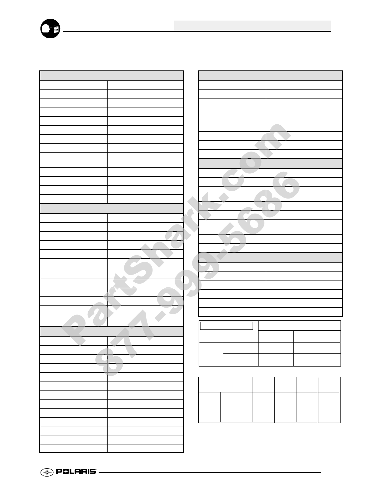
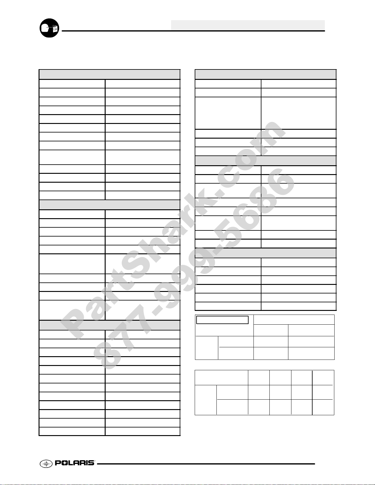
Model Identification 1.2.......................
Serial Number Location 1.2...................
Replacement Keys 1.3.......................
Machine Dimensions 1.3.....................
Publication Numbers 1.3.....................
Paint Codes 1.3.............................
Specifications - Trail Boss 330 1.4--1.5.............
Specifications - Trail Blazer 330 1.6--1.7............
Specs
Special Tools 1.8............................
Standard Torque Specifications 1.9............
Tap / Drill Charts 1.10.........................
Decimal Equivalent Chart 1.10.................
Unit of Measure Conversion Table 1.11..........
Glossary of Terms 1.12........................
1.1
Page 2
GENERAL INFORMATION
PartShark.com
877-999-5686
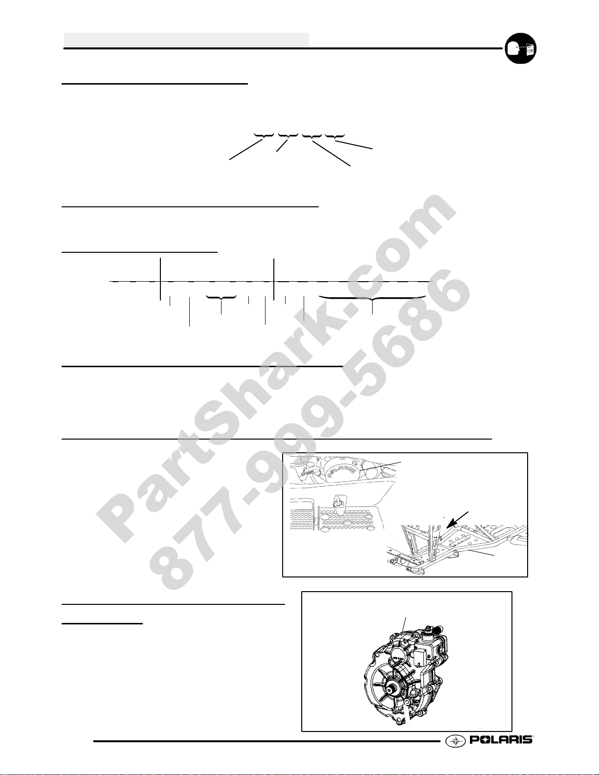
MODEL IDENTIFICATION
The machine model number must be used with any correspondence regarding warranty or service.
Machine Model Number Identification
A09CA32AA
Emissions &
Year Designation
Basic Chassis
Designation Engine Designation
Model Option
ENGINE DESIGNATION NUMBERS
ES32PFE Single, Air Cooled, SOHC 4 Stroke, Electric Start..................
VIN IDENTIFICATION
World Mfg. ID
1 2 3 4 5 6 7 8 9 10 11 12 13 14 15 16 17
4XAAA
Vehicle Descriptor
32A*9P0 00000
Vehicle Identifier
Body Style
Powertrain
Emissions
Engine
Check Digit
Model
Year
Plant No.
Individual Serial No.
* This could be either
a number or a letter
ENGINE SERIAL NUMBER LOCATION
Whenever corresponding about an engine, be sure to refer to the engine model number and serial number. This
information can be found on the sticker applied to the recoil housing on the right side of engine.(A) An additional
number is stamped on the center top of crankcase beneath the cylinder coolant elbow.
UNIT MODEL NUMBER AND SERIAL NUMBER LOCATION
Themachinemodelnumber andserialnumberare
important for vehicle identification. The machine
serial number is stamped on the lower left side of
the frame tube.(B)
A
Front
B
TRANSMISSION I.D. NUMBER
LOCA
TION
The transmission I.D. number is located
on top of the transmission, right side of
machine.
1.2
Page 3
PUBLICATION NUMBERS
PartShark.com
877-999-5686
GENERAL INFORMATION
Year Model Model No. Owner’s
Manual PN
2009 Trail Boss 330 A09CA32AA 9921784 9921774
2009 Trail Blazer 330 A09BA32AA 9921773 9921787
NOTE: When ordering service parts be sure to use the correct parts manual.
NOTE: Some manuals can be found at the Polaris website: www.polarisindustries.com or purchased from
www.purepolaris.com.
Parts
Manual PN
PAINT CODES
FRAME COLOR - P067 Medium Gloss Black 9440 / 8520147.
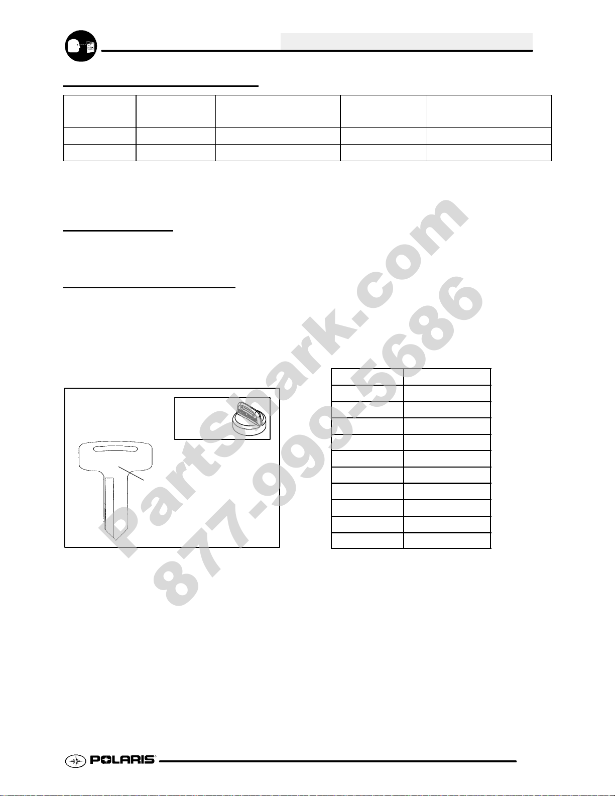
REPLACEMENT KEYS
Replacement keys can be made from the original
key. To identify which series the key is, take the
first two digits on the original key and refer to the
chart to the right for the proper part number.
Shouldbothkeysbecomelost, ignition switch
replacement is required.
Series # Part Number
20 4010278
31XX
KEY COVER
P/N 5433534
Key Series
Number
21 4010278
22 4010321
23 4010321
27 4010321
28 4010321
31 4110141
32 4110148
67 4010278
68 4010278
1.3
Page 4
GENERAL INFORMATION
PartShark.com
877-999-5686
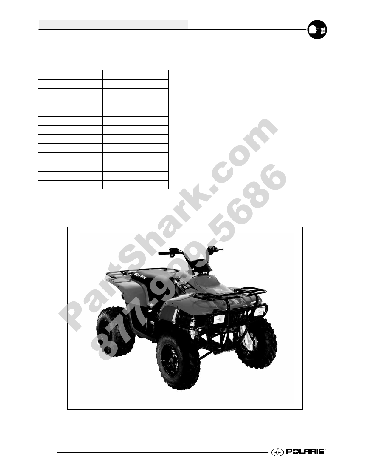
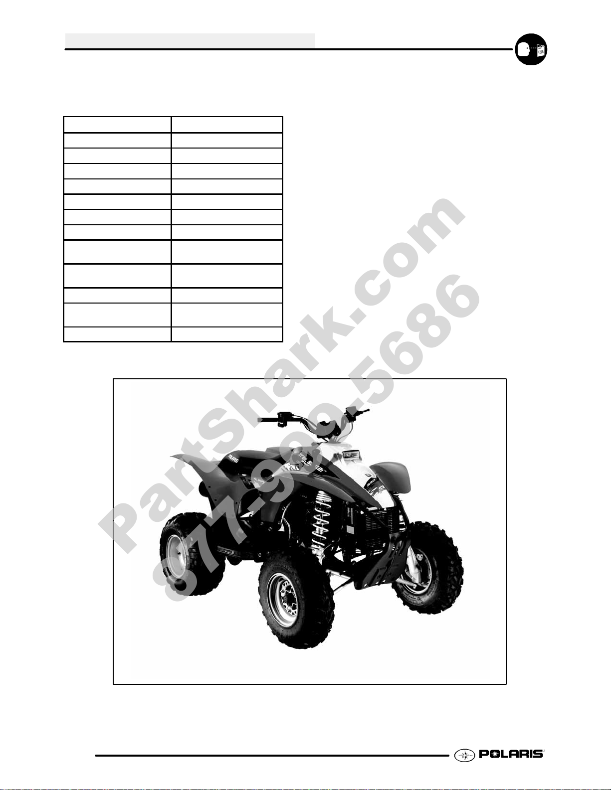
MODEL: 2009 TRAILBOSS 330..........
MODEL NUMBER: A09CA32AA.
ENGINE MODEL: ES32PFE..
Category
Length 75 in./191 cm
Width 46 in./117 cm
Height 46 in./117 cm
Wheel Base 49.5 in./125.73 cm
Ground Clearance 5.5./13.97 cm
Dry Weight 505 lbs./230 kg
Gross Vehicle Weight 845 lbs./383 kg
Front Rack Capacity
Rear Rack Capacity
Towing Capacity
Hitch TongueWeight
Body Style
Dimension
75 lbs./34 kg
125 lbs./57 kg
850 lbs./385 kg
85 lbs./14 kg
Gen IV
1.4
Page 5
GENERAL INFORMATION
PartShark.com
877-999-5686
MODEL: 2009 TRAILBOSS 330..........
MODEL NUMBER: A09CA32AA.
ENGINE MODEL: ES32PFE..
Engine
Platform Fuji 4 stroke, Single Cylinder
Engine Model Number EH32PFE
Engine Displacement 329cc
Number of Cylinders 1
Bore & Stroke (mm) 78.5 x 68 mm
CompressionRatio 9.2:1
Compression Pressure 70--90 psi
Engine Idle Speed 1300 ± 100 Rpm
Cooling System/Capacity Oil/ Air w/ fan assist
1.9qts./1.8 ltr
Overheat Warning HOT Light on Panel
Lubrication Wet Sump
Oil Requirements Polaris 2W--50
Exhaust System USFS Approved
Carburetion
Carburetor model Mikuni BST 34mm
Main Jet 122.5
Pilot Jet 42.5
Jet Needle 4HB48--3
Needle Jet P--4 (829)
Pilot Screw 2 Turns Out
(Initial starting point, may vary
for each ATV)
Pilot Air Jet 160
Float Height 13 ± 1 mm (0.51 ± 0.40“)
Fuel Delivery Fuel Pump
Fuel Capacity / Requirement 3.25 gal. (12.3 L)
87 Octane (minimum)
89 Oxygenated
Electrical
Alternator Output 200 w @ 5000 RPM
Voltage Regulator 3--Phase
Lights : High Beam 2x30 watts
Low Beam 2x30 watts
Brake 26.9 watts
Tail 8.26 watts
Ignition System DC/CDI Ignition
Ignition Timing 30°±2° BTDC @ 5000 RPM
Spark plug / Gap NGK BKR6E/ .036 in./0.9mm
Battery / Model / Amp Hr Maintenance--Free -- 14 Amp Hr
Circuit Breakers Harness 20 amp
Starting Electric / Recoil Backup
Indicator Panel Standard
Drivetrain
Transmission Type Inline H/N/R
Transmission Capacity 11.3 oz. (335 ml)
Gear Ratio : High
Rev.
Final
Chain Type 520 O--Ring
Clutch Type PVT Non EBS
Belt 3211077
2.68/1
3.05/1
11/40 78P
Steering / Suspension
Front Suspension / Shock A--arm / MacPherson Strut
Front Travel 8.2 in. / 20.83 cm
Rear Suspension
Style / Shock
Rear Travel 10.5 in. / 26.67 cm
Ground Clearance 5.5in. / 13.97 cm
Shock Preload Adjustment
Front / Rear
Turning Radius 83in./211cm
Toe Out 1/8 -- 1/4 in / 3 -- 6.35 mm
Progressive Rate Swingarm /
Twin Tube Gas Charged
Front -- n/a
Rear -- Cam
Wheels / Brakes
Wheel Size -- Front / Pattern 23 x 7 -- 10 / 4--156
Wheel Size -- Rear / Pattern 22 x 11 -- 10 / 4--102
Air Press. F/R Tires 4 psi Front / 3 psi Rear
Brake -- Front Dual Hydraulic Disc
Brake -- Rear Single Hydraulic Disc
Brake Fluid Polaris DOT 4 Brake Fluid
JETTING CHART
Altitude
Meters
(Feet)
0--1800
(0--6000)
above 1800
(above 6000)
AMBIENT TEMPERATURE
Below 40°F
Below 5°C
127.5 122.5
120
+40°Fto+80°F
+5°Cto+28°C
115
CLUTCH CHART
Driven
Helix
(5131446)
(5131446)
Meters
(Feet)
Altitude
0--1800
(0--6000)
1800--3700
(6000--12000)
Shift
Weight
10 RH
(5630709)
20--40
(5631356)
Drive
Spring
Blu/Grn
(7041157)
Blu/Grn
Driven
Spring
Black
(7041782)
Black
(7041782)(7041157)
45°
2--2
45°
2--2
1.5
Page 6
GENERAL INFORMATION
PartShark.com
877-999-5686
MODEL: 2009 TRAILBLAZER 330..........
MODEL NUMBER: A09BA32AA.
ENGINE MODEL: ES32PFE..
Category
Length 75 in./191 cm
Width 46 in./117 cm
Height 46 in./117 cm
Wheel Base 48 in./121.9 cm
Ground Clearance 5.5./13.97 cm
Dry Weight 488 lbs./221 kg
Gross Vehicle Weight 830 lbs./377 kg
Front Rack Capacity
(Accessory)
Rear Rack Capacity
(Accessory)
Towing Capacity
Hitch TongueWeight
(Accessory)
Body Style
Dimension
30 lbs./13.6 kg
60 lbs./27.2 kg
850 lbs./385 kg
85 lbs./14 kg
Gen III
1.6
Page 7
MODEL: 2009 TRAILBLAZER 330..........
PartShark.com
877-999-5686
MODEL NUMBER: A09BA32AA.
ENGINE MODEL: ES32PFE..
Engine
Platform Fuji 4 stroke, Single Cylinder
Engine Model Number ES32PFE
Engine Displacement 329cc
Number of Cylinders 1
Bore & Stroke (mm) 78.5 x 68 mm
CompressionRatio 9.2:1
Compression Pressure 70--90 psi
Engine Idle Speed 1300 ± 100 Rpm
Cooling System/Capacity Oil/ Air w/ fan assist
1.9qts./1.8 ltr
Overheat Warning HOT Light on Panel
Lubrication Wet Sump
Oil Requirements Polaris 2W--50
Exhaust System USFS Approved
Carburetion
Carburetor model Mikuni BST 34mm
Main Jet 122.5
Pilot Jet 42.5
Jet Needle 4HB48--3
Needle Jet P--4 (829)
Pilot Screw 2 Turns Out
(Initial starting point, may vary
for each ATV)
Pilot Air Jet 160
Float Height 13 ± 1 mm (0.51 ± 0.40“)
Fuel Delivery Fuel Pump
Fuel Capacity / Requirement 3.25 gal. (12.3 L)
87 Octane (minimum)
89 Oxygenated
Electrical
Alternator Output 200 w @ 5000 RPM
Voltage Regulator 3--Phase
Lights : Head 55 watts
Brake 26.9 watts
Tail 8.26 watts
Ignition System DC/CDI Ignition
Ignition Timing 30°±2° BTDC @ 5000 RPM
Spark plug / Gap NGK BKR6E/ .036 in./0.9mm
Battery / Model / Amp Hr Maintenance--Free -- 14 Amp Hr
Circuit Breakers Harness 20 amp
Starting Electric / Recoil Backup
Indicator Panel Standard
GENERAL INFORMATION
Drivetrain
Transmission Type Inline H/N/R
Transmission Capacity 11.3 oz. (335 ml)
Gear Ratio : High
Rev.
Final
Chain Type 520 O--Ring
Clutch Type PVT Non EBS
Belt 3211077
Steering / Suspension
Front Suspension / Shock A--arm / MacPherson Strut
Front Travel 8.2 in. / 20.83 cm
Rear Suspension
Style / Shock
Rear Travel 10.5 in. / 26.67 cm
Ground Clearance 5.5in. / 13.97 cm
Shock Preload Adjustment
Front / Rear
Turning Radius 83in./211cm
Toe Out 1/8 -- 1/4 in / 3 -- 6.35 mm
Progressive Rate Swingarm /
Twin Tube Gas Charged
Wheels / Brakes
Wheel Size -- Front / Pattern 23 x 7 -- 10 / 4--156
Wheel Size -- Rear / Pattern 22 x 11 -- 10 / 4--102
Air Press. F/R Tires 4 psi Front / 3 psi Rear
Brake -- Front Dual Hydraulic Disc
Brake -- Rear Single Hydraulic Disc
Brake Fluid Polaris DOT 4 Brake Fluid
JETTING CHART
Altitude
Meters
(Feet)
0--1800
(0--6000)
above 1800
(above 6000)
AMBIENT TEMPERATURE
Below 40°F
Below 5°C
127.5 122.5
120
CLUTCH CHART
Shift
Weight
10 RH
(5630709)
20--40
(5631356)
Blu/Grn
Blu/Grn
Meters
(Feet)
Altitude
0--1800
(0--6000)
1800--3700
(6000--12000)
Drive
Spring
(7041157)
2.68/1
3.05/1
11/40 78P
Front -- n/a
Rear -- Cam
+40°Fto+80°F
+5°Cto+28°C
Driven
Spring
Black
(7041782)
Black
(7041782)(7041157)
115
Driven
Helix
(5131446)
(5131446)
45°
2--2
45°
2--2
1.7
Page 8
GENERAL INFORMATION
PartShark.com
877-999-5686
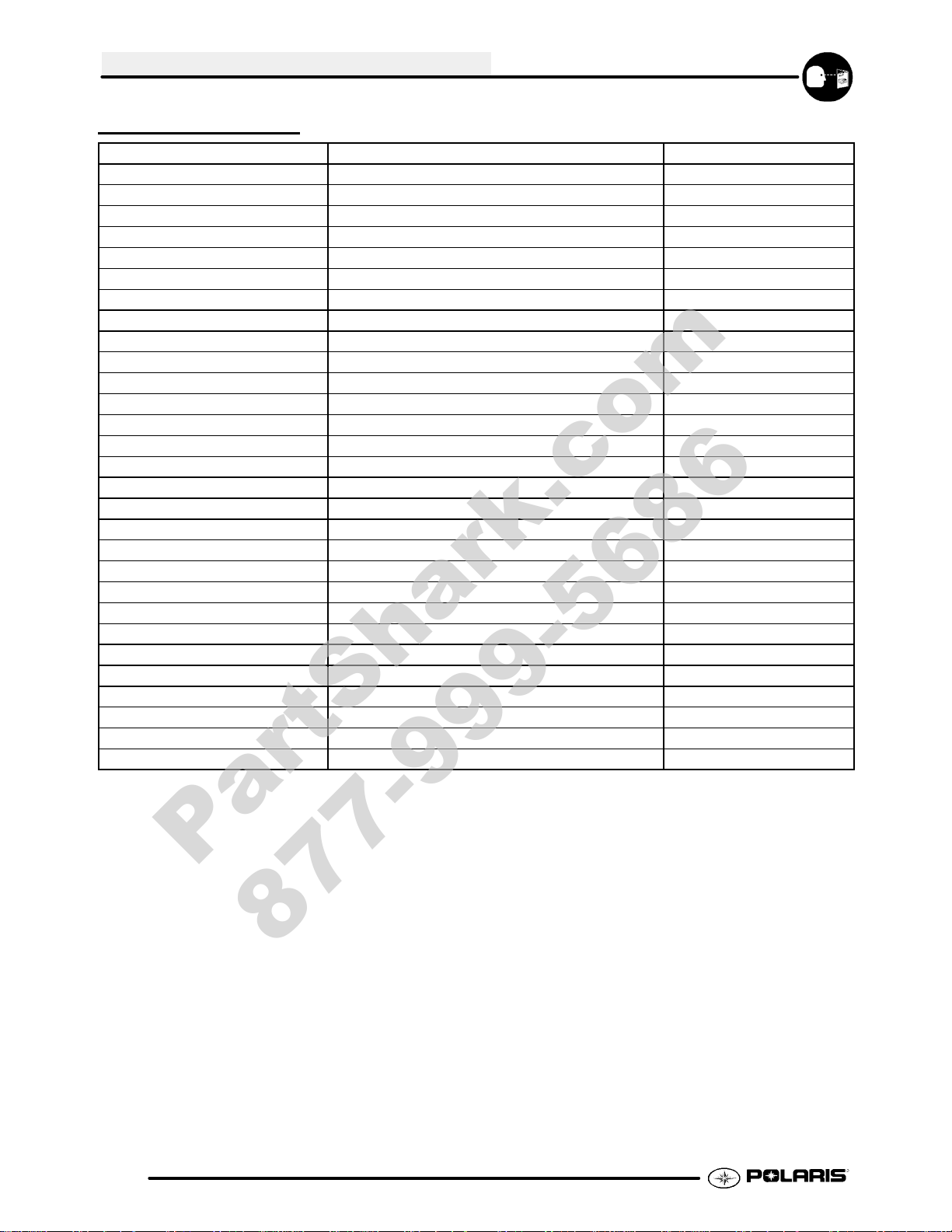
SPECIAL TOOLS
PART NUMBER TOOL DESCRIPTION CHAPTER TOOL USED IN
PA--44689 Valve Clutch Adjuster 2
2870872 Shock Spanner Wrench 2, 5
8712100DX or 8712500 Tachometer 2,10
2200634 Valve Seat Reconditioning Kit 3
2870390 Piston Support Block 3
2870159 FlywheelPuller 3
2871293 Slotted Nut Socket 3
PV--43527 OIl Filter Wrench 3
2872314 CarburetorFloat Adjustment Tool 4
2870975 Mity Vact Pressure Test Tool 4, 9
2870871 BallJoint Replacement Tool 5
2870623 Shock Absorber Spring Compression Tool 5
2871573 LH Strut Spring Compressor 5
2871574 RH Strut Spring Compressor 5
2870506 Clutch Puller 6
9314177 Clutch Holding Wrench 6
2871358 ClutchHolding Fixture 6
2870341 Drive Clutch Spider Removal and Install Tool 6
2870654 Clutch Offset Alignment Tool 6
2870913 Driven Clutch Puller 6
2870910 Roller Pin Tool 6
2871226 ClutchBushing Replacement Tool Kit 6
2870386 Piston Pin Puller 6
8700220 Clutch Compression Tool 6
2871710 10” Center Distance Tool 8
PV--43568 Fluket77 Digital Multimeter 10
2870630 Timing Light 10
2870836 Battery Hydrometer 10
8712100 or 8712500 Tachometer 10
NOTE: Polaris dealers can order the tools listed above through the SPX Service T ools catalog.
1.8
Page 9
GENERAL INFORMATION
PartShark.com
877-999-5686
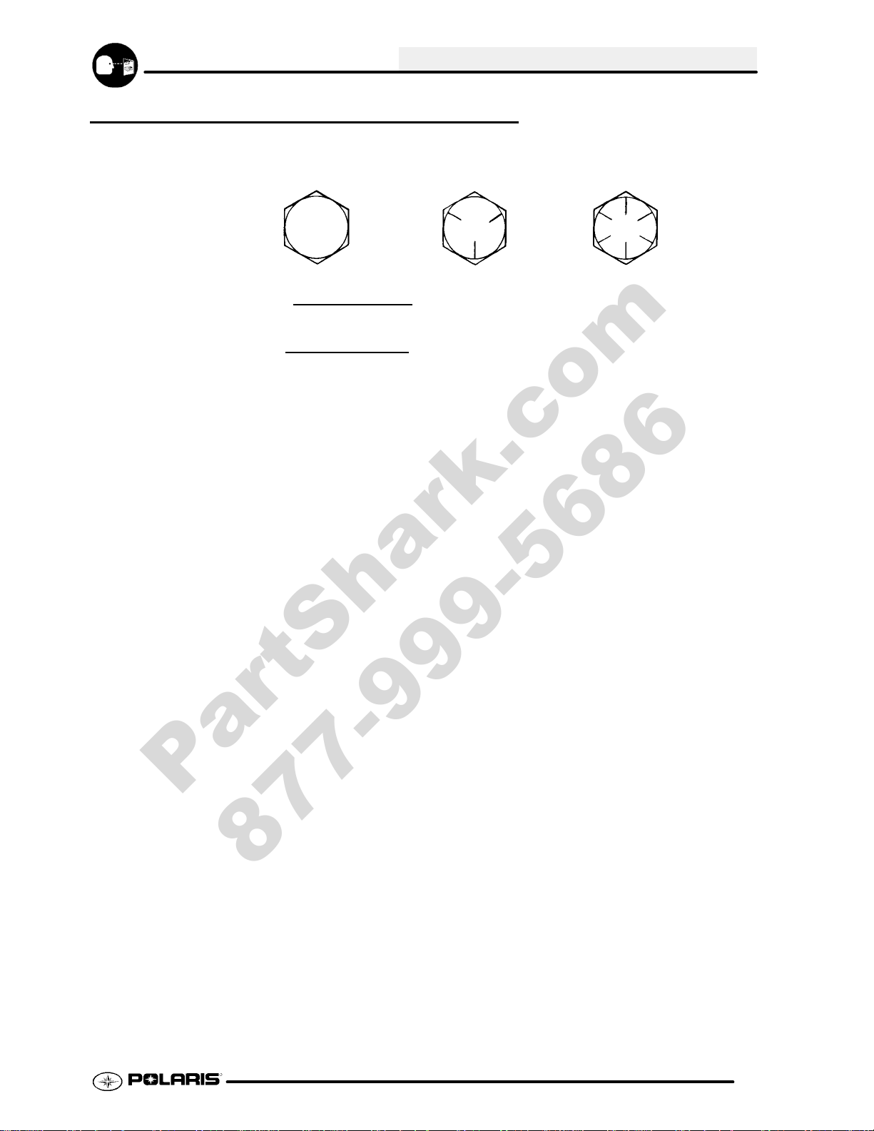
STANDARD TORQUE SPECIFICATIONS
Thefollowing torquespecificationsare tobeused as a generalguideline. FOR SPECIFICTORQUE VALUESOF
FASTENERS Refer to exploded views in the appropriate section. There are exceptions in the steering,
suspension, and engine sections.
Bolt Size Threads/In Grade 2 Grade 5 Grade 8
T orque in. lbs. (Nm)
#10 - 24 27 (3.1) 43 (5.0) 60 (6.9).............. ................ ..............
#10 - 32 31 (3.6) 49 (5.6) 68 (7.8).............. ................ ..............
T o rque ft. lbs. (Nm)*
1/4 - 20 5 (7) 8 (11) 12 (16).............. .................. ................
1/4 - 28 6 (8) 10 (14) 14 (19).............. .................. ..............
5/16 - 18 11 (15) 17 (23) 25 (35).............. ................ ..............
5/16 - 24 12 (16) 19 (26) 29 (40).............. ................ ..............
3/8 - 16 20 (27) 30 (40) 45 (62).............. ................ ..............
3/8 - 24 23 (32) 35 (48) 50 (69).............. ................ ..............
7/16 - 14 30 (40) 50 (69) 70 (97).............. ................ ..............
7/16 - 20 35 (48) 55 (76) 80 (110).............. ................ ..............
1/2 - 13 50 (69) 75 (104) 110 (152).............. ................ .............
1/2 - 20 55 (76) 90 (124) 120 (166).............. ................ .............
Metric / Torque
6 x 1.0 72-78 In. lbs. 8 x 1.25 14-18ft. lbs. 10 x 1.25 26-30 ft. lbs..... ......
1.9
Page 10
GENERAL INFORMATION
PartShark.com
877-999-5686
SAE TAP DRILL SIZES
Thread Size/Drill Size Thread Size/Drill Size
#0-80 3/64
#1-64 53
#1-72 53
#2-56 51
#2-64 50
#3-48 5/64
#3-56 45
#4-40 43
#4-48 42
#5-40 38
#5-44 37
#6-32 36
#6-40 33
#8-32 29
#8-36 29
#10-24 24
#10-32 21
#12-24 17
#12-28 4.6mm
1/4-20 7
1/4-28 3
5/16-18 F
5/16-24 I
3/8-16 O
3/8-24 Q
7/16-14 U
7/16-20 25/64
1/2-13 27/64
1/2-20 29/64
9/16-12 31/64
9/16-18 33/64
5/8-11 17/32
5/8-18 37/64
3/4-10 21/32
3/4-16 1 1/16
7/8-9 49/64
7/8-14 13/16
1-8 7/8
1-12 59/64
1 1/8-7 63/64
1 1/8-12 1 3/64
11/4-7 17/64
1 1/4-12 1 11/64
11/2-6 111/32
1 1/2-12 1 27/64
13/4-5 19/16
1 3/4-12 1 43/64
2-4 1/2 1 25/32
2-12 1 59/64
2 1/4-4 1/2 2 1/32
21/2-4 21/4
23/4-4 21/2
3-4 2 3/4
METRIC TAP DRILL SIZES
Tap Size Drill Size Decimal
Equiva-
lent
3x.50
3x.60
4x.70
4x.75
5x.80
5x.90
6 x 1.00
7 x 1.00
8 x 1.00
8 x 1.25
9 x 1.00
9 x 1.25
10 x 1.25
10 x 1.50
11 x 1.50
12 x 1.50
12 x 1.75
#39
3/32
#30
1/8
#19
#20
#9
16/64
J
17/64
5/16
5/16
11/32
R
3/8
13/32
13/32
0.0995
0.0937
0.1285
0.125
0.166
0.161
0.196
0.234
0.277
0.265
0.3125
0.3125
0.3437
0.339
0.375
0.406
0.406
Nearest
Fraction
3/32
3/32
1/8
1/8
11/64
5/32
13/64
15/64
9/32
17/64
5/16
5/16
11/32
11/32
3/8
13/32
13/32
DECIMAL EQUIVALENTS
1/64 .0156................
1/32 .0312 1 mm = .0394″........... ...
3/64 .0469................
1/16 .0625...........
5/64 .0781 2 mm = .0787″................ ...
3/32 .0938...........
7/64 .1094 3 mm = .1181″.............. ...
1/8. .1250...
9/64 .1406................
5/32 .1563 4 mm = .1575″........... ...
11/64 .1719...............
3/16 .1875 5 mm = .1969″........... ...
13/64 .2031...............
7/32 .2188...........
15/64 .2344 6 mm = .2362″............... ...
1/4 .25....
17/64 .2656 7 mm = .2756″............... ...
9/32 .2813...........
19/64 .2969...............
5/16 .3125 8 mm = .3150″........... ...
21/64 .3281...............
11/32 .3438 9 mm = .3543″.......... ...
23/64 .3594...............
3/8 .375....
25/64 .3906 10 mm = .3937″............... ...
13/32 .4063.........
27/64 .4219 11 mm = .4331″............... ...
7/16 .4375...........
29/64 .4531...............
15/32 .4688 12 mm = .4724″......... ...
31/64 .4844...............
1/2 .5 13 mm = .5118.... ..............
33/64 .5156...............
17/32 .5313.........
35/64 .5469 14 mm = .5512″............... ...
9/16 .5625...........
37/64 .5781 15 mm = .5906″............... ...
19/32 .5938.........
39/64 .6094...............
5/8 .625 16 mm = .6299″.... ............
41/64 .6406...............
21/32 .6563 17 mm = .6693″......... ...
43/64 .6719..............
1/16 .6875..........
1
45/64 .7031 18 mm = .7087″............... ...
23/32 .7188.........
47/64 .7344 19 mm = .7480″............... ...
3/4 .75....
49/64 .7656...............
25/32 .7813 20 mm = .7874″......... ...
51/64 .7969...............
13/16 .8125 21 mm = .8268″......... ...
53/64 .8281...............
27/32 .8438.........
55/64 .8594 22 mm = .8661″............... ...
7/8 .875....
57/64 .8906 23 mm = .9055″............... ...
29/32 .9063.........
59/64 .9219..............
15/16 .9375 24 mm = .9449″......... ...
61/64 .9531...............
31/32 .9688 25 mm = .9843......... ...
63/64 .9844...............
11.0.....
1.10
Page 11
GENERAL INFORMATION
PartShark.com
877-999-5686
CONVERSION TABLE
Unit of Measure Multiplied by Converts to
ft. lbs. x12 =in.lbs.
in. lbs. x .0833 = ft. lbs.
ft. lbs. x 1.356 =Nm
in. lbs. x .0115 =kg-m
Nm x .7376 = ft.lbs.
kg-m x 7.233 = ft. lbs.
kg-m x 86.796 =in.lbs.
kg-m x10 =Nm
in. x 25.4 =mm
mm x .03937 =in.
in. x2.54 =cm
mile (mi.) x1.6 =km
km x .6214 = mile (mi.)
Ounces (oz) x 28.35 = Grams (g)
Fluid Ounces (fl. oz.) x 29.57 = Cubic Centimeters (cc)
Cubic Centimeters (cc) x .03381 = Fluid Ounces (fl. oz.)
Grams (g) x 0.035 = Ounces (oz)
lb. x .454 =kg
kg x 2.2046 =lb.
Cubic inches (cu in) x 16.387 = Cubic centimeters (cc)
Cubic centimeters (cc) x 0.061 = Cubic inches (cu in)
Imperial pints (Imp pt) x 0.568 = Liters (l)
Liters (l) x1.76 = Imperial pints (Imp pt)
Imperial quarts (Imp qt) x 1.137 = Liters (l)
Liters (l) x0.88 = Imperial quarts (Imp qt)
Imperial quarts (Imp qt) x 1.201 = US quarts (US qt)
US quarts (US qt) x 0.833 = Imperial quarts (Imp qt)
US quarts (US qt) x 0.946 = Liters (l)
Liters (l) x 1.057 = US quarts (US qt)
US gallons (US gal) x 3.785 =Liters (l)
Liters (l) x 0.264 = US gallons (US gal)
Pounds - force per square inch (psi) x 6.895 = Kilopascals (kPa)
Kilopascals (kPa) x 0.145 = Pounds - force per square inch (psi)
Kilopascals (kPa) x0.01 = Kilograms - force per square cm
Kilograms - force per square cm x 98.1 = Kilopascals (kPa)
π (3.14) xR2x H (height) = Cylinder Volume
°Cto°F: 9 (°C + 40) ÷ 5-40=°F
°Fto°C: 5 (°F + 40) ÷ 9-40=°C
1.11
Page 12
GENERAL INFORMATION
PartShark.com
877-999-5686
GLOSSARY OF TERMS
ABDC: After bottom dead center.
ACV: Alternating current voltage.
Alternator: Electrical generator producing voltage alternating current.
ATDC: After top dead center.
BBDC: Before bottom dead center.
BDC: Bottom dead center.
BTDC: Before top dead center.
CC: Cubic centimeters.
Center Distance: Distance between center of crankshaft and center of driven clutch shaft.
Chain Pitch: Distance between chain link pins (No.35 = 3/8″ or1 cm). Polaris measures chainlength in number of pitches.
CI: Cubic inches.
Clutch Buttons: Plastic bushings which aid rotation of the movable sheave in the drive and driven clutch.
ClutchOffset: Drive anddriven clutchesare offset sothatdrive beltwill staynearly straightas it movesalong the clutchface.
Clutch Weights: Three levers in the driveclutch which relative to theirweight, profile and engine RPMcause thedrive
clutch to close and grip the drive belt.
Crankshaft Run-Out: Run-out or “bend” of crankshaft measured with a dial indicator while crankshaft is supported
between centers on V blocks or resting in crankcase. Measure at various points especially at PTO.
DCV: Direct current voltage.
Dial Bore Gauge: A cylinder measuring instrument which uses a dial indicator. Good for showing taper and
out-of-round in the cylinder bore.
Electrical Open: Open circuit. An electrical circuit which isn’t complete.
Electrical Short: Short circuit. Anelectrical circuit which is completed before the current reaches the intended load.
(i.e. a bare wire touching the chassis).
End Seals: Rubber seals at each end of the crankshaft.
Engagement RPM: Engine RPM at which the drive clutch engages to make contact with the drive belt.
ft.: Foot/feet.
Foot Pound: Ft. lb. A force of one pound at the end of a lever one foot in length, applied in a rotational direction.
g: Gram. Unit of weight in the metric system.
gal.: Gallon.
ID: Inside diameter.
in.: Inch/inches.
Inch Pound: In. lb. 12 in. lbs. = 1 ft. lb.
kg/cm2: Kilograms per square centimeter.
kg-m: Kilogram meters.
Kilogram/meter: A force of one kilogram at the end of a lever one meter in length, applied in a rotational direction.
lorltr: Liter.
lbs/in2: Pounds per square inch.
Left or Right Side: Always referred to based on normal operating position of the driver.
m: Meter/meters.
Mag: Magneto.
Magnetic Induction: As a conductor (coil) is moved through a magnetic field, a voltage will be generated in the
windings. Mechanical energy is converted to electrical energy in the stator.
mi.: Mile/miles.
mm: Millimeter. Unit of length in the metric system. 1mm = approximately .040″.
Nm: Newton meters.
OD: Outside diameter .
Ohm: The unit of electrical resistance opposing current flow.
oz.: Ounce/ounces.
Piston Clearance: Total distance between piston and cylinder wall.
psi.: Pounds per square inch.
PTO: Power take off.
PVT: Polaris Variable Transmission (Drive Clutch System)
qt.: Quart/quarts.
Regulator: Voltage regulator. Regulates battery charging system output at approx. 14.5 DCV as engine RPM increases.
Reservoir T ank: Thefill tank in the liquid cooling system.
Resistance: In the mechanical sense, friction or load. In the electrical sense, ohms, resulting in energy conversion to heat.
RPM: Revolutions per minute.
SeizedPiston: Gallingofthe sides ofa piston. Usuallythereis atransferofaluminumfromthepistonontothecylinderwall.
Possible causes: 1)improper lubrication; 2)excessive temperatures; 3) insufficient piston clearance; 4) stuck piston rings.
Stator Plate: The plate mounted under the flywheel supporting the battery charging coils.
TDC: Top dead center. Piston’s most outward travel from crankshaft.
Volt: The unit of measure for electrical pressure of electromotive force. Measured by a voltmeter in parallel with the circuit.
Watt: Unit of electrical power. Watts = amperes x volts.
WOT: Wide open throttle.
1.12
Page 13
MAINTENANCE
PartShark.com
877-999-5686
Periodic Maintenance Chart 2.2-2.5...............
Recommended Maintenance Products 2.6--2.7......
Pre-Ride Inspection 2.8......................
ATV Component Locations 2.9................
Lubricant and Maintenance Quick Reference 2.10-2.11
Transmission Lubrication 2.12..................
Lubrications/Grease Points 2.13................
Transmission Linkage Adjustment 2.13..........
Throttle Operation / Choke Adjustment 2.14......
Carburetor Adjustments 2.15-2.16...................
ETC Switch Adjustment 2.16--2.17...................
Fuel System 2.17-2.18.............................
Compression Test 2.18........................
Battery Maintenance 2.19......................
Ignition / Sparkplug 2.20.......................
Air Filter Service 2.20-2.21.........................
Air Box Sediment Tube Service 2.22............
Recoil Housing/PVT Drying 2.22................
Oil Level/Change/Filter 2.23-2.24....................
Valve Clearance 2.24-2.25.........................
Steering and Toe Alignment 2.25-2.27...............
Exhaust System Maintenance 2.28.............
Brake System Service 2.28-2.29....................
Drive Chain and Sprocket Service 2.29-2.32..........
Suspension Service / Controls 2.32-2.33.............
Wheel Removal / Installation 2.33--2.34...............
Tire Inspection 2.34...........................
2.1
Page 14
MAINTENANCE
PartShark.com
877-999-5686
PERIODIC MAINTENANCE CHART
Careful periodic maintenance will help keep your vehicle in the safest, most reliable condition. Inspection,
adjustment and lubrication of important components are explained in the periodic maintenance chart.
Inspect, clean, lubricate, adjust and replace parts as necessary. When inspection reveals the need for
replacement parts, use genuine Polaris parts available from your Polaris dealer.
NOTE: Service and adjustments are critical. If you’re not familiar with safe service and adjustment
procedures, have a qualified dealer perform these operations.
Maintenance intervals in the following chart are based upon average riding conditions and an average vehicle
speedofapproximately10 milesperhour. Vehiclessubjectedto severeuse mustbe inspectedandservicedmore
frequently.
Severe Use Definition
G Frequent immersion in mud, water or sand
G Racing or race-style high RPM use
G Prolonged low speed, heavy load operation
G Extended idle
G Short trip cold weather operation
Pay special attention to the oil level. A rise in oil level during cold weather can indicate contaminants collecting
in the oil sump or crankcase. Change oil immediately if the oil level begins to rise. Monitor the oil level, and if
it continues to rise, discontinue use and determine the cause or see your dealer.
Maintenance Chart Key
The following symbols denote potential items to be aware of during maintenance:
H= CAUTION: Due to the nature of these adjustments, it is recommended this service be performed
by an authorized Polaris dealer.
"= SEVERE USE ITEM ----If vehicle is subjected to severe use, decrease interval by 50%
(Severe Use is defined as frequent vehicle immersion in mud, water or sand, racing or race-style high rpm
use, prolonged low speed - heavy load operation or extended idle. More preventative maintenance is
required under these conditions. Fluid changes, cable, chain and chassis lubrication are required more
frequently. For engine oil, short trip cold weather riding also constitutes severe use. Pay special attention
to oil level. A rising oil level in cold weather can indicate contaminants collecting in the oil sump or
crankcase. Change oil immediately and monitor level. If oil level begins to rise, discontinue use and
determine cause.)
E= Emission Control System Service (California).
NOTE: Inspection may reveal the need for replacement parts. Always use genuine Polaris parts.
WARNING: Improperly performing the procedures marked with a
to serious injury or death. Have an authorized Polaris dealer perform these services.
J could result in component failure and lead
2.2
Page 15
MAINTENANCE AND LUBRICATION
j
PartShark.com
877-999-5686
Periodic Maintenance Chart
MAINTENANCE
Item Maintenance Interval
(whichever comes first)
Hours Calendar Miles
(Km)
J
Steering
"
Front suspension
"
Rear suspension
Tires
"
Brake fluid level
"
Brake lever travel
Brake systems
Drive Chain
Wheels/fasteners
Frame fasteners
"
Engine oil level
E
"
Air filter, pre-filter
E
"
Air box sediment
E
tube
Coolant
--
--
--
--
--
--
--
--
--
--
--
--
--
--
Pre-Ride
Pre-Ride
Pre-Ride
Pre-Ride
Pre-Ride
Pre-Ride
Pre-Ride
Pre-Ride
Pre-Ride
Pre-Ride
Pre-Ride
Daily
Daily
Daily
--
--
--
--
--
--
--
--
--
--
--
--
--
--
Make adjustments as needed.
Inspect; clean often
Drain deposits when visible
Check level daily, change coolant every 2 years
(if applicable)
Headlamp/tail
lamp
"
Air filter,
E
main element
Recoil housing
--
--
--
Daily
Weekly
Weekly
--
Check operation; apply dielectric grease if replacing
--
--
Inspect; replace as needed
Drain water as needed, check often if operating
in wet conditions
"
Brake pad wear 10 H Monthly 60 (100) Inspect periodically
J
Battery 20 H Monthly 125 (200) Check terminals; clean; test
"
Front gearcase oil
25 H Monthly 155 (250) Inspect level; change yearly
(if equipped)
"
Middle gearcase
25 H Monthly 155 (250) Inspect level; change yearly
oil (if equipped)
"
Rear gearcase oil
25 H Monthly 155 (250) Inspect level; change yearly
(if equipped)
"
Transmission oil 25 H Monthly 155 (250) Inspect level; change yearly
Remarks
" Perform these procedures more often for vehicles
subjected to severe use.
E Emission Control System Service (California)
J Have an authorized Polaris dealer perform these
services.
2.3
Page 16
MAINTENANCE
PartShark.com
877-999-5686
MAINTENANCE AND LUBRICATION
Periodic Maintenance Chart
Item Maintenance Interval
Hours Calendar Miles
"
Engine breather
E
filter (if equipped)
"
Engine oil change
E
(break-in)
"
General
lubrication
Shift Linkage 50 H 6M 310 (500) Inspect, lubricate, adjust
J
Steering 50 H 6M 310 (500) Lubricate
"
Front suspension 50 H 6M 310 (500) Lubricate
"
Rear suspension 50 H 6M 310 (500) Lubricate
Carburetor float
bowl
J
Throttle Cable/
E
ETC Switch
J
Choke cable 50 H 6M 310 (500) Inspect; adjust; lubricate; replace if necessary
E
E
Carburetor air
intake ducts/
flange
Drive belt 50 H 6M 310 (500) Inspect; adjust; replace as needed
Cooling system
(if applicable)
"
Engine oil change 100 H 6M 620
E
"
Oil filter change 100 H 6M 620
E
"
Oil tank vent hose 100 H 12 M 620
E
J
Valve clearance 100 H 12 M 620
E
25 H Monthly 155 (250) Inspect; replace if necessary
25 H 1M 155 (250) Perform a break-in oil change at one month
50 H 3M 310 (500) Lubricate all grease fittings, pivots, cables, etc.
50 H 6M 310 (500) Drain bowl periodically and prior to storage
50 H 6M 310 (500) Inspect; adjust; lubricate; replace if necessary
50 H 6M 310 (500) Inspect ducts for proper sealing/air leaks
50 H 6M 310 (500) Inspect coolant strength
(whichever comes first)
(Km)
(1000)
(1000)
(1000)
(1000)
seasonally; pressure test
system yearly
Perform a break-in oil change at 25 hours/one
month
Replace with oil change
Inspect routing, condition
Inspect; adjust
Remarks
" Perform these procedures more often for vehicles
subjected to severe use.
E Emission Control System Service (California)
J Have an authorized Polaris dealer perform these
services.
2.4
Page 17
MAINTENANCE AND LUBRICATION
PartShark.com
877-999-5686
Periodic Maintenance Chart
MAINTENANCE
Item Maintenance Interval
Hours Calendar Miles
J
Fuel system 100 H 12 M 620
E
J
Fuel filter 100 H 12 M 620
E
"
Radiator
(if applicable)
"
Cooling hoses
(if applicable)
"
Engine mounts 100 H 12 M 620
Exhaust muffler/
pipe
J
Spark plug 100 H 12 M 620
E
J
Ignition Timing 100 H 12 M 620
E
"
Wiring 100 H 12 M 620
J
Clutches (drive
and driven)
J
Front wheel
bearings
J
Brake fluid 200 H 24 M 1240
Spark arrestor 300 H 36 M 1860
E
Idle speed
J
Toe adjustment
"
Auxiliary brake
J
Headlight aim
100 H 12 M 620
100 H 12 M 620
100 H 12 M 620
100 H 12 M 620
100 H 12 M 1000
(whichever comes first)
--
--
--
--
(Km)
(1000)
(1000)
(1000)
(1000)
(1000)
(1000)
(1000)
(1000)
(1000)
(1000)
(1600)
(2000)
(3000)
Remarks
Check for leaks at tank cap, lines, fuel valve, filter, pump, carburetor; replace lines every two
years
Replace yearly
Inspect; clean external
surfaces
Inspect for leaks
Inspect
Inspect
Inspect; replace as needed
Inspect
Inspect for wear, routing,
security; apply dielectric grease to connectors
subjected to water, mud, etc.
Inspect; clean; replace worn parts
Inspect; replace as needed
Change every two years
Clean out
Adjust as needed
Inspect periodically; adjust when parts are replaced
Inspect daily; adjust as needed
Adjust as needed
" Perform these procedures more often for vehicles
subjected to severe use.
E Emission Control System Service (California)
J Have an authorized Polaris dealer perform these
services.
2.5
Page 18
MAINTENANCE
PartShark.com
877-999-5686
POLARIS LUBES/FLUIDS FOR TRAILBOSS 330 MODELS
Pure Polaris Lubricants and Maintenance Kits can be purchased at your local Polaris dealer.
2.6
Page 19
MAINTENANCE
PartShark.com
877-999-5686
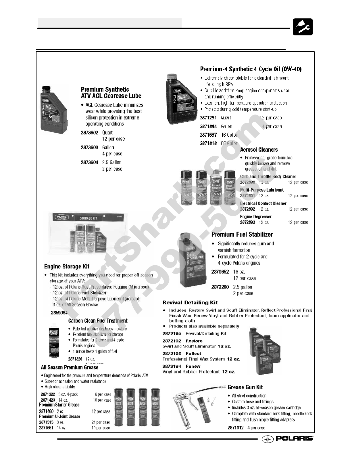
POLARIS LUBRICANTS,MAINTENANCE AND SERVICE PRODUCTS
Part No. Description
Engine Lubricant
2870791 FoggingOil (12 oz. Aerosol)
2876244 Engine Oil (Quart)Premium 4 Synthetic
2W--50 (4--Cycle) (12 Count)
2876245 Engine Oil (Gallon) Premium 4 Synthetic
2W--50 (4--Cycle) (4 Count)
Gearcase / Transmission Lubricants
2873602 Premium Synthetic AGL Gearcase Lube
(12 oz. bottle)(12 Count)
2873603 Premium Synthetic AGL Gearcase Lube
(1 Gal.) (4 Count)
2876160 Premium ATV Angle Drive Fluid
(32 oz.) (12 Count)
2872276 Premium ATVAngle Drive Fluid
(2.5 Gal) (2 Count)
2870465 Oil Pump for 1 Gallon Jug
2871654 Premium Demand Drive Hub Fluid
(8 oz.) (12 Count)
Grease / Specialized Lubricants
2871322 Premium All Season Grease
(3 oz. cartridge)(24 Count)
2871423 Premium All Season Grease
(14 oz. cartridge)(10 Count)
2871460 StarterDrive Grease (12 Count)
2871515 Premium U-Joint Lube (3 oz.) (24 Count)
2871551 Premium U-Joint Lube (14 oz.) (10 Count)
2871312 Grease Gun Kit
2871329 DielectricGrease (Nyogelt)
Coolant
2871323 60/40 Coolant (Gallon) (6 Count)
2871534 60/40 Coolant (Quart) (12 Count)
Part No. Description
Additives / Sealants / Thread Locking Agents /
Misc.
2874275 Loctitet Primer N, Aerosol
2871956 Loctitet Thread Sealant 565
(50 ml.)(6 Count)
2871950 Loctitet Threadlock 242
(6 ml.)(12 Count)
2871951 Loctitet Threadlock 262
(50 ml.) (10 Count)
2871953 Loctitet Threadlock 271
(6 ml.)(12 Count)
2871326 Premium Carbon Clean
(12 oz.) (12 Count)
2870652 Fuel Stabilizer (16 oz.) (12 Count)
2871957 Black RTV Silicone Sealer
(3 oz. tube) (12 Count)
2871958 Black RTV Silicone Sealer
(11 oz. cartridge) (12 Count)
2872189 DOT 4 Brake Fluid (12 Count)
2871557 CrankcaseSealant, 3-Bond 1215 (5oz.)
NOTE: The number count indicated by each part
number in the table above indicates the number of
units that are shipped with each order.
NOTE: Each item can be purchased separately at
your local Polaris dealer.
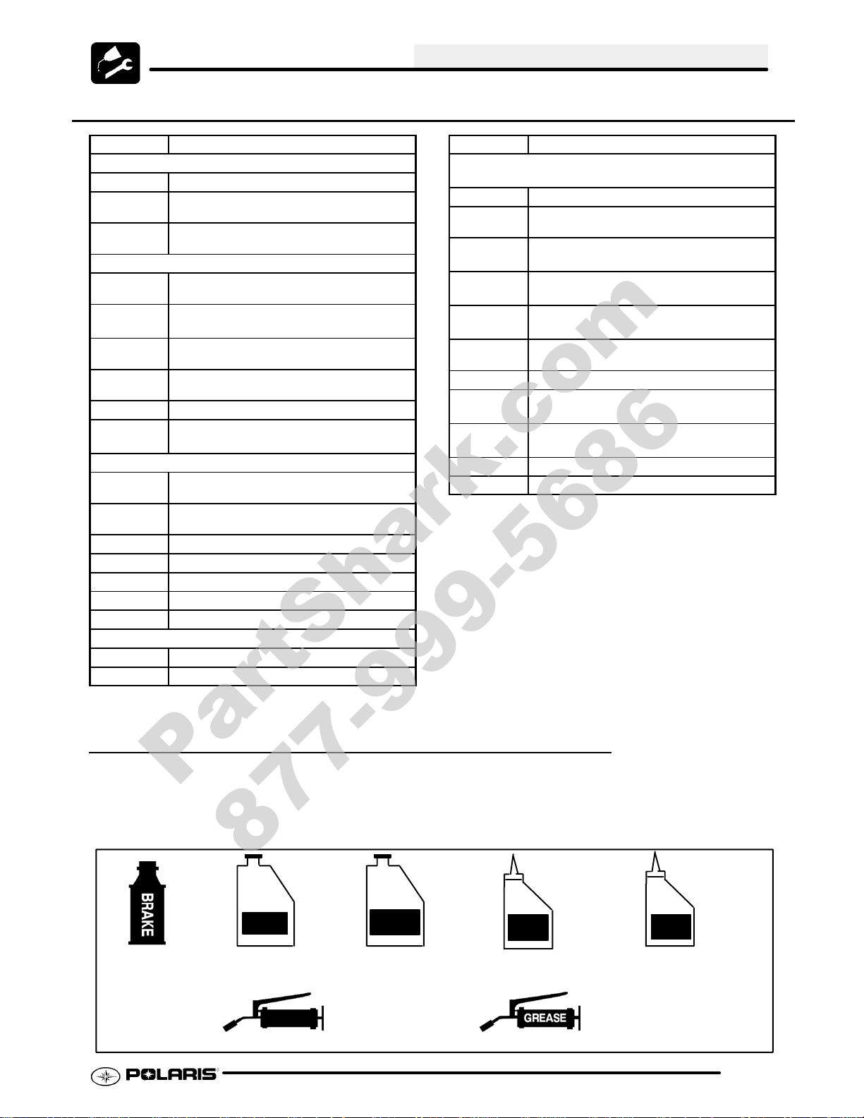
POLARIS LUBRICANT SYMBOL IDENTIFICATON
AGL
Polaris DOT 4
Brake Fluid
Polaris Sythetic
Gearcase Lube
AGL
U--Joint
Polaris U--Joint Lube
2W/50
Polaris Sythetic
OW--40 Oil
DHF
Polaris Demand
Drive Hub Fluid
Polaris All Season Grease
ADF
Polaris ATV
Angle Drive Fluid
2.7
Page 20
MAINTENANCE
PartShark.com
877-999-5686
PRE-RIDE / DAILY INSPECTION
Perform the following pre-ride inspection daily, and when servicing the vehicle at each scheduled maintenance.
G Tires - check condition and pressures
G Fuel and oil tanks - fill both tanks to their proper level; Do not overfill oil tank
G All brakes - check operation (includes auxiliary brake)
G Throttle - check for free operation
G Headlight/Taillight/Brakelight - check operation of all indicator lights and switches
G Engine stop switch - check for proper function
G Wheels - check for loose wheel nuts
G Air cleaner element - check for dirt or water; clean or replace
G Steering - check for free operation, noting any unusual looseness in any area
G Loose parts - visually inspect vehicle for any damaged or loose nuts, bolts or fasteners
G Engine coolant - check for proper level at the recovery bottle
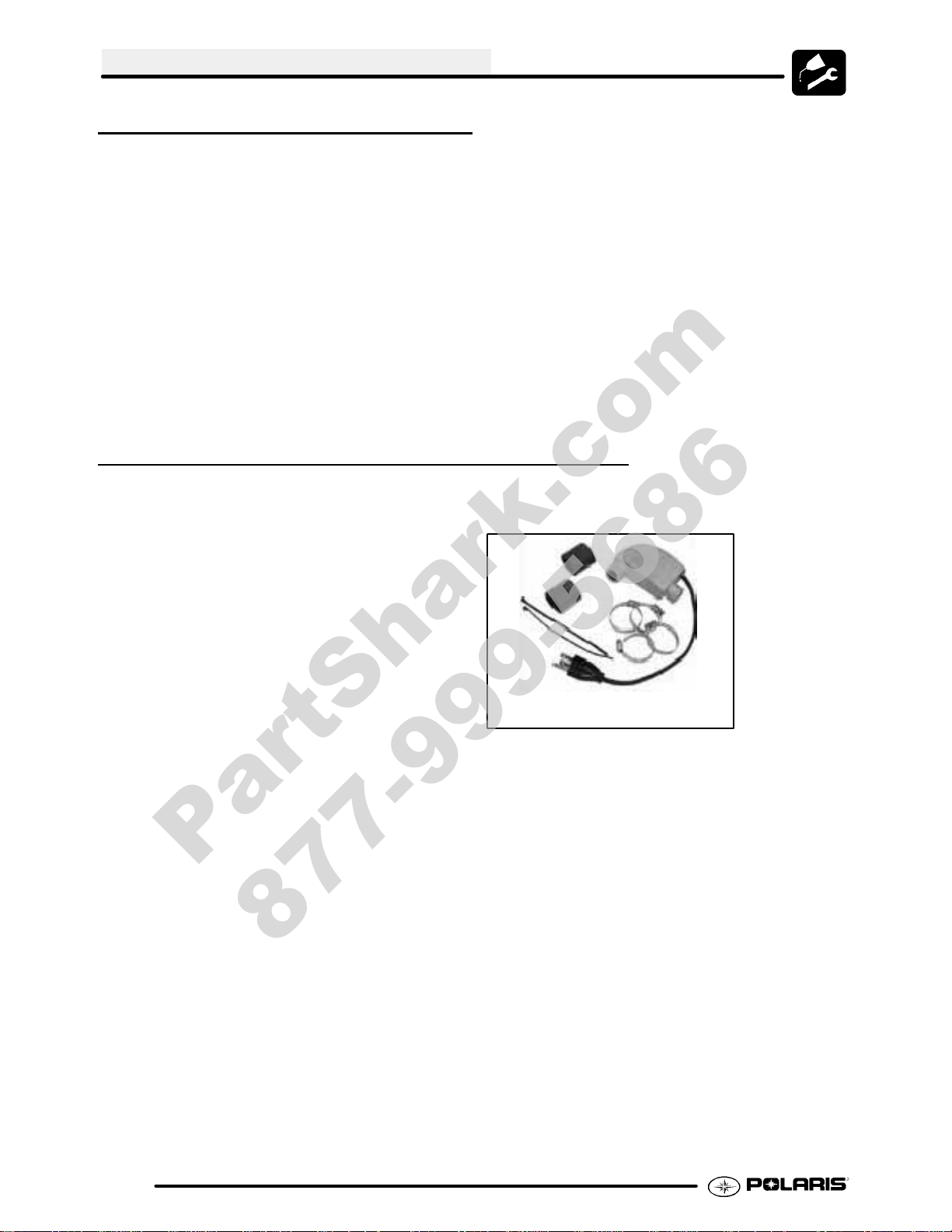
COLD WEATHER KITS FOR 4 STROKE ATVS
Engine Heater -- (PN 2871507)
ACCESSORY ENGINE HEATER
2.8
Page 21
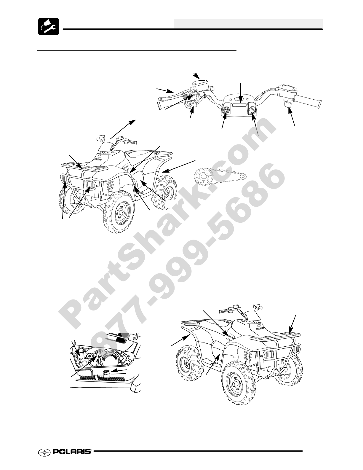
TRAIL BOSS 330 COMPONENT LOCATIONS
PartShark.com
877-999-5686
Brake Fluid Reservoir
Brake Lever
Light Control
& Run Switch
Fuel Valve
Front Rack
Reverse
Override
Choke
Rear Axle &
Drive Sprocket
MAINTENANCE
Display
Throttle
Ignition/Key
Headlights
Transmission
Engine
Recoil
Right Side View
Oil Dipstick
Muffler
Auxiliary Brake
PVT Cover
Gear Shifter
Front Rack
Engine
2.9
Page 22
MAINTENANCE
PartShark.com
877-999-5686
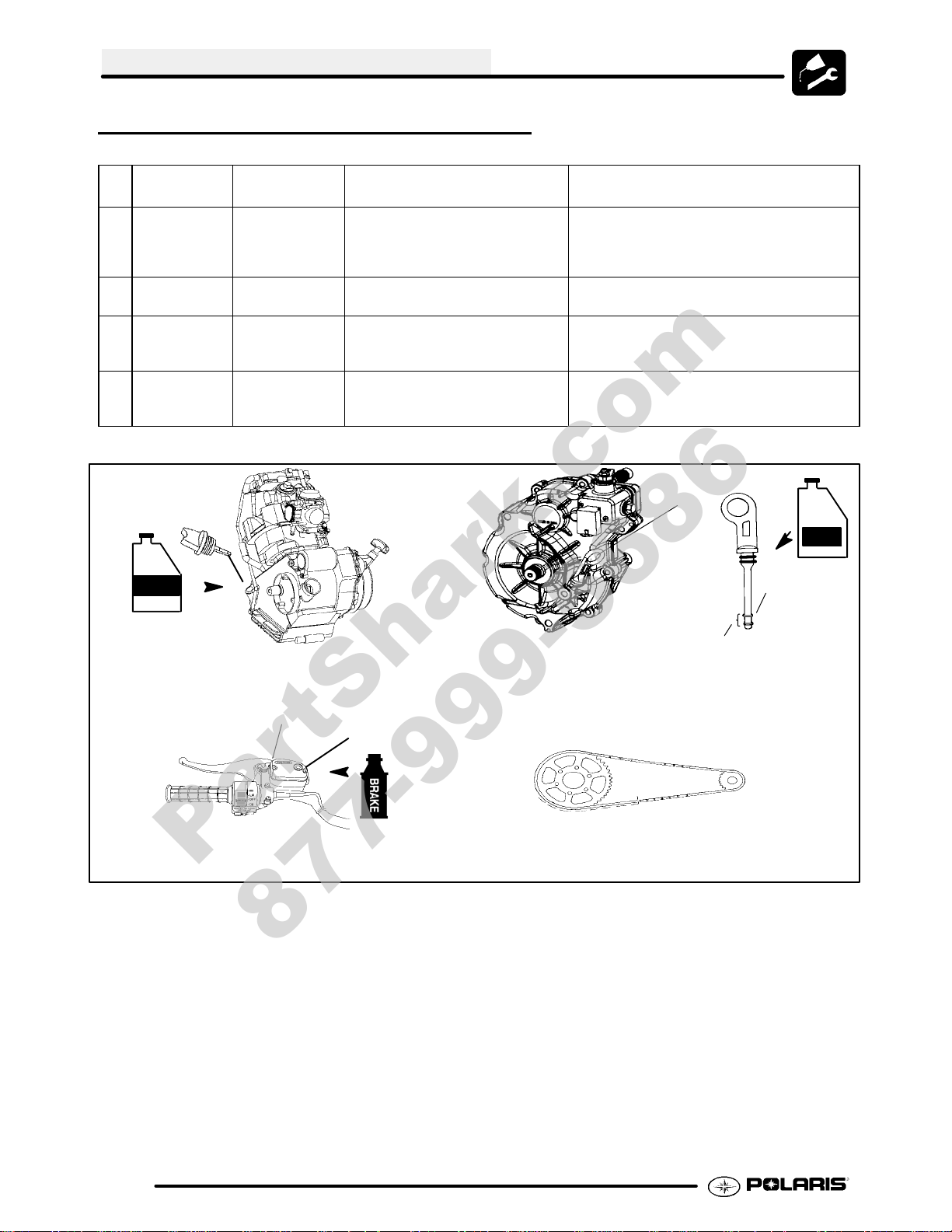
MAINTENANCE QUICK REFERENCE
Ill.
#
1 Engine Oil Polaris 2W--50
2 Transmission PolarisAGL Lu-
3 Brake Fluid Polaris DOT 3
4 DriveChain Polaris Chain
NOTE: Refer to Page 2.6 for the Polaris Lubricant Identification table.
Item Lube Rec. Method Frequency*
Add oil to proper level. Change after1st month, 6 months or 100
Synthetic
Add lube to FULL level on dip-
bricant
Brake Fluid
Lube or O-Ring
chain lube
Dipstick
2W/50
stick.
Fill master cylinder reservoir to in-
dicated level inside reservoir. See
Page 2.29.
Apply to chain link plates and rollers.
hours thereafter; Change more often (25-50
hours) in extremely dirty conditions, or short
trip cold weather operation.
Change annually ©
As required. Change fluid every 2 years.
As required*
Transmission
Dipstick
AGL
Operating
Range
Full
1. Engine Oil
Parking Brake Lock
3. Brake Fluid
2. Transmission
Reservoir
4. Rear Drive Chain
2.10
Page 23
MAINTENANCE QUICK REFERENCE CONT’D
PartShark.com
877-999-5686
MAINTENANCE
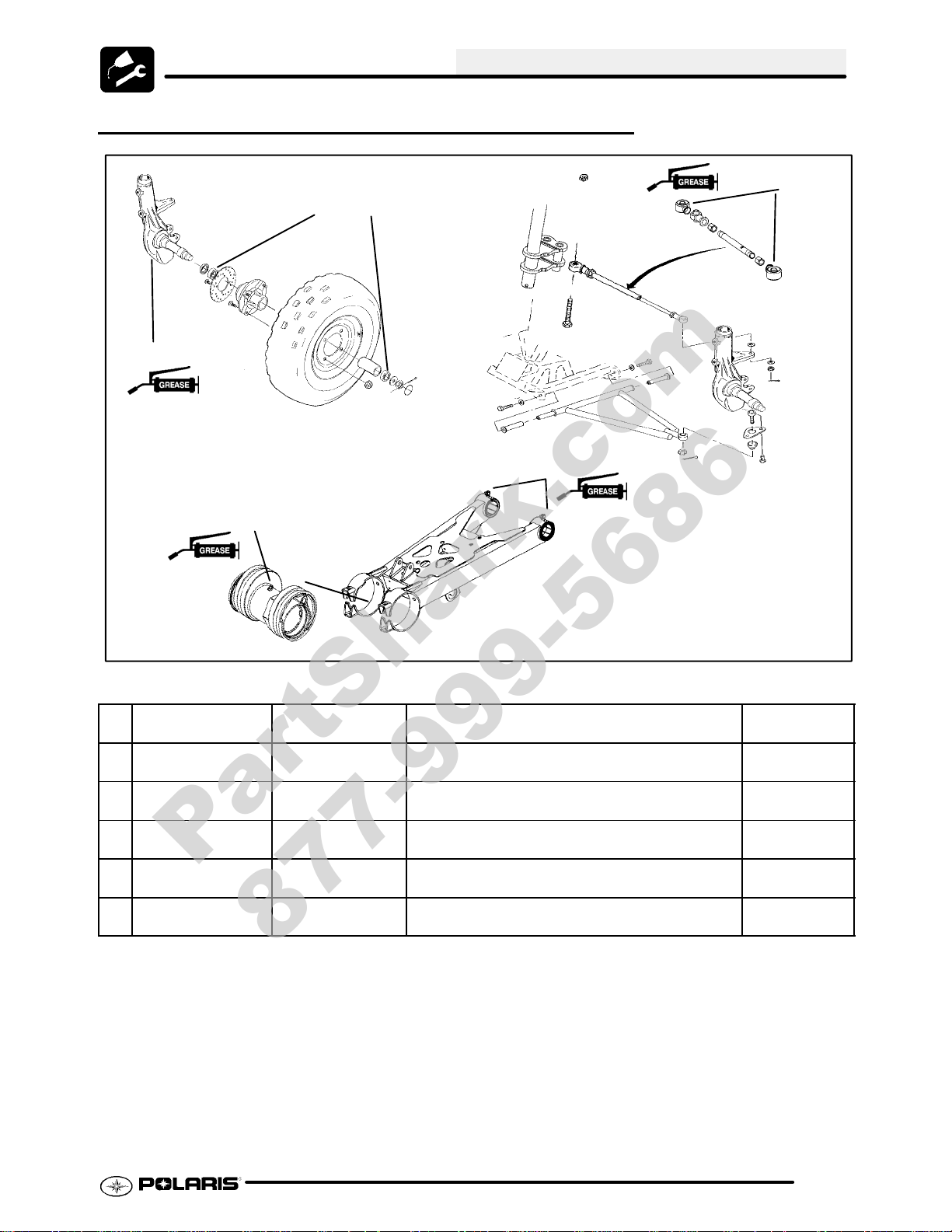
5. Ball Joint
8. Axle Housing
4. Front
Wheel
Bearings
6. Tie Rod Ends
7. Swingarm Pivots
NOTE: Refer to Page 2.6 for the Polaris Lubricant Identification table.
Ill.
#
4 FrontWheel Bear-
ings
5 Ball Joint Polaris All Season
6 Tie Rod Ends Polaris All Season
7 Swing Arm Bush-
ings
8 Rear Axle Housing Polaris All Season
* More often under severe use, such as operated in water or under severe loads.
¡ Semi-annually or 50 hours of operation (refer to Maintenance Schedule for additional information)
© Annually or 100 hours of operation (refer to Maintenance Schedule for additional information)
¢ Grease conforming to NLGI No. 2, such as Polaris Premium All Season Grease, Conoco Superlube M or
Mobilegrease Special
Item Lube Rec. Method Frequency*
Sealed; Replace Inspect and replace bearings if necessary Annually ©
Grease¢
Grease¢
Polaris All Season
Grease¢
Grease¢
Locate grease fitting on back side of struts and
grease with grease gun.
Lift boot. Clean away dirt and grease. Apply fresh
grease by hand and reassemble.
Locate grease fitting on swing arm and grease with
grease gun.
Locate grease fitting on eccentric and grease with
grease gun.
Semi-annually
¡
Semi-annually
¡
Semi-annually
¡
Semi-annually
¡
2.11
Page 24
MAINTENANCE
PartShark.com
877-999-5686
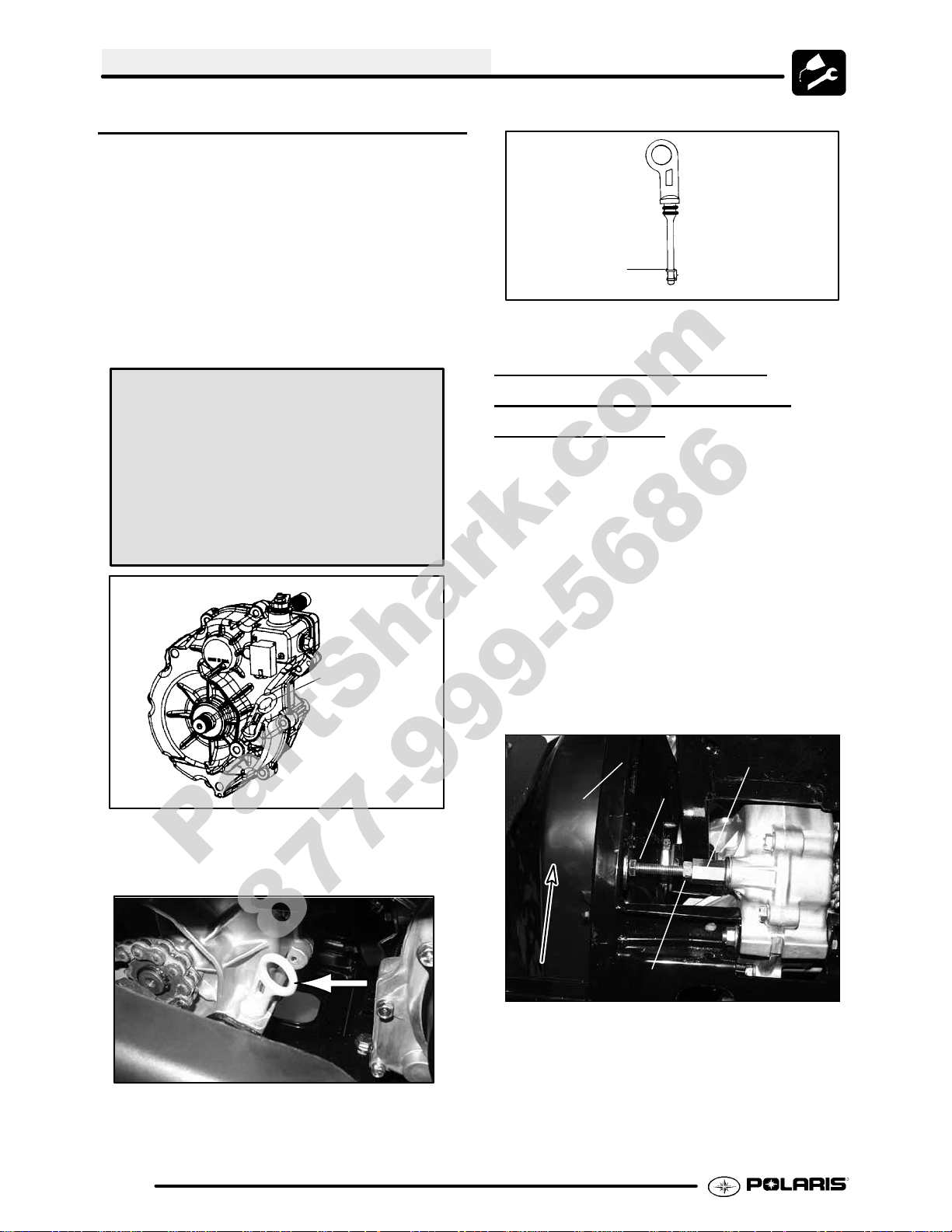
TRANSMISSION LUBRICATION
The transmission lubricant level should be checked
and changed in accordance with the maintenance
schedule.
G Be sure vehicle is level before
proceeding.
G Check vent hose to be sure it is
routed properly and unobstructed.
G Follow instructions on following
pages to check / change
transmission lubricant.
TRANSMISSION SPECIFICATIONS
Specified Lubricant:
Polaris AGL Gearcase Lubricant:
(PN 2873603) (Gallon) (PN 2873602) (12 oz.)
Capacity: 11.3 oz. (335 ml)
Drain Plug / Fill Plug T orque:
14 ft. lbs. (19.4 Nm)
Transmission
Dipstick
Full
Operating
Range
TRANSMISSION FLUID
CHANGE/TORQUE ST
OP
ADJUSTMENT
1. Remove skid plate (if necessary).
2. Place a drain pan beneath the transmission oil
drain plug area.
3. Loosen jam nut (A).
4. Turn adjuster bolt (B) in to allow the removal of
drain plug.
5. Removethedrainplug andwipethe magneticend
clean to remove accumulated metallic filings.
6. After the oil has drained completely, install a new
sealing washer and install the drain plug. Torque
to 14 ft. lbs. (19.3 Nm).
7. Turn adjuster bolt (B) out until it touches the
frame, and then an additional 1/2 turn.
PVT Cover
B
To check the level:
1. Remove dipstick and wipe clean.
Forward
8. Tighten the jam nut securely while holding the
adjuster bolt.
9. Addthe proper lubricant through the dipstick hole
until the oil level is between the upper and lower
2. Reinstall dipstick completely, remove and check
the level. Add the proper lubricant as required to
bring level into operating range as shown.
limits. Do not overfill.
10. Check for leaks.
11.ReinstallskidplateifremovedinStep1.
A
Drain Plug
2.12
Page 25
MAINTENANCE
PartShark.com
877-999-5686
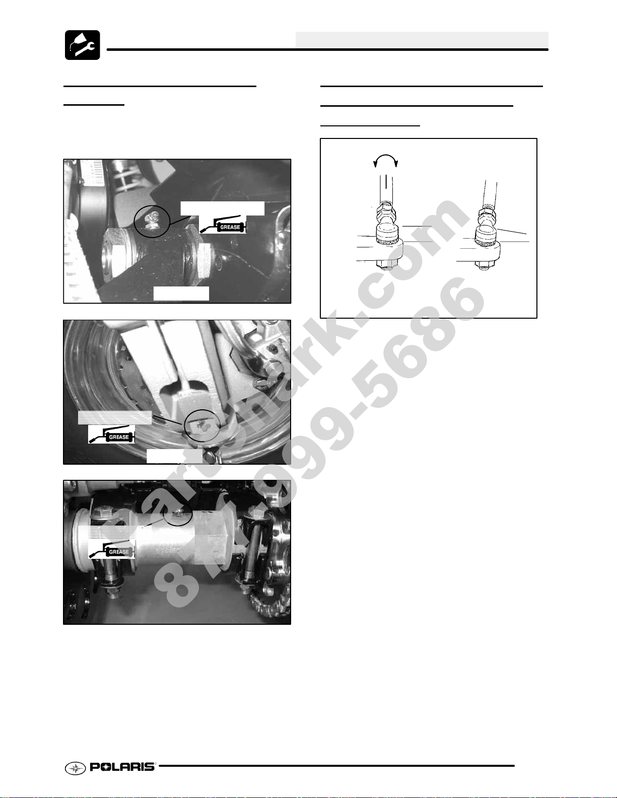
LUBRICATION / GREASE
POINTS
As shown on Page 2.8, there are only five grease
zerks onthe TrailBoss,two front balljoints,two onthe
swing are pivots, and one on the rear axle housing.
Swing Arm Pivot
Each Side
Ball Joint Zerk
Each Side
Ball Joint Zerk
TRANSMISSION GEARSHIFT
LINKAGE
ADJUSTMENT/
INSPECTION
Linkage rod will rotate
1/8 -1/4 turn if rod ends
are tightened properly.
Parallel
Correctly Tightened
Jam Nut
G Ifshiftingproblems areencountered,
thetransmission linkagemayrequire
adjustment.
G Visually check for contact of shift
lever to shifter opening in the front
fender. Ensure shift linkage or shift
lever is not contacting the frame or
exhaust components.
G Tightenshiftlinkage rodendjam nuts
properly after adjustment. You
should be able to rotate the linkage
rod between 1/8 and 1/4 turn after
both jam nuts are tight.
G The transmission shift linkage
should be periodically inspected for
wear and parts replaced as required
to remove excess play from shift
linkage.
G Refer to Transmission chapter for
more information.
Incorrectly Tightened
Jam Nut
NOTE: Therod end must be held whentighteningthe
jam nut to prevent damage to the rod end.
2.13
Page 26
MAINTENANCE
PartShark.com
877-999-5686
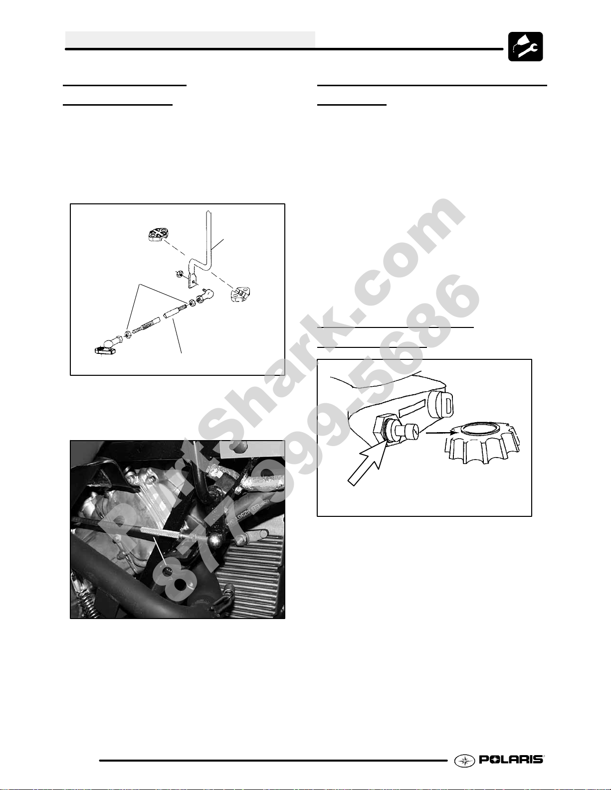
SHIFT LINKAGE
ADJUSTMENT
1. Inspect shift linkage tie rod ends, clevis and pivot
bushings and replace if worn or damaged.
2. Place gear selector in neutral.
3. Loosen rod end adjuster jam nuts (A) on both
ends of linkage rod. NOTE: The jam nut closest
to the knurled end is Left Hand thread.
Jam Nuts (A)
Linkage Rod
Ill. 1
THROTTLE OPERATION - ALL
MODELS
Check for smooth throttle opening and closing in all
handlebar positions. Throttle lever operation should
be smooth and lever must return freely without
binding.
1. Place the gear selector in neutral.
2. Set parking brake.
3. Start the engine and let it idle.
4. Turn handlebars from full right to full left. If idle
speed increases at any point inthe turningrange,
inspect throttle cable routing and condition. If
cable is routed properly and in good condition,
repeat adjustment procedure.
5. Replace the throttle cable if worn, kinked, or
damaged.
CHOKE (ENRICHER)
ADJUSTMENT
4. Turn linkage rod (A) to shorten or lengthen rod
until the shift lever is centered on hole in the fender.
A
5. Hold rod end parallel to mounting surface and
tighten jam nuts securely.
Boot
If the choke knob does not stay out when pulled,
adjust the choke tension by tightening the tensioner
located under the rubber boot between the choke
knob and nut. Firmly grasp the rubber boot and
tighten until thechoke slides freely but stays out when
pulled.
Verify free play of 1/16--3/16” (1.6--4.76 mm) and
smooth operation of choke cable.
If smooth choke operation is not obtainable, inspect
choke cable for kinks or sharp bends in routing.
2.14
Page 27
MAINTENANCE
PartShark.com
877-999-5686
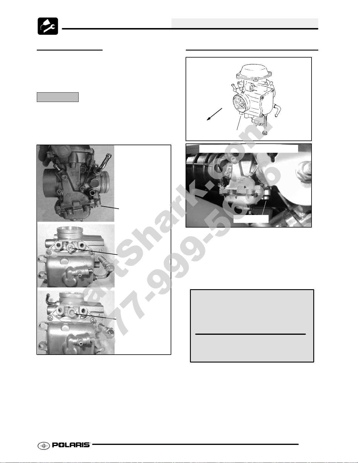
PILOT SCREW
Thepilotsystem suppliesfuelduringengine operation
with the throttle valve closed or slightly opened. The
fuel/air mixture is metered by pilot screw and
discharged into the main bore through the pilot outlet.
CAUTION:
The pilotscrew is calibratedatthe factoryto meetEPA/ CARB
regulationsfor air qualitystandards and is sealed with a brass
plug to prevent tampering. Removal of the tamper proof plug
is not permitted. For service purposes, cleaning of the pilot
circuitcan be done only by a certifiedrepairshop to ensure air
quality standards are not exceeded.
Pilot Screw location
PILOT SCREW ADJUSTMENT
FRONT
(Engine)
Pilot Screw
View -- Right Cover Panel Removed
Pilot Screw
1. Start engine and warm it up to operating
temperature (about 10 minutes).
Brass Plug Installed
Brass Plug Removed
2. Turnpilot screw in (clockwise) until lightly seated.
Turn screw out the specified number of turns.
NOTE: Do not tighten the pilot screw forcefully
against the seat or the screw and/or seat will be
permanently damaged.
The pilot screw is set at the factory.
Each carburetor will have a slightly different pilot screw setting, the adjustments below are the recommended settings, the settings may differ from these
recommendations.
Pilot Screw Adjustment:
Trailboss 330 -- 2 Turns Out
3. Connect an accurate tachometer that will read in
increments of + or -- 50 RPM such as the PET
2100DX (PN 8712100DX) or the PET 2500 (PN
8712500).
4. Set idle speed to 1200 RPM. Always check
throttle cable freeplay after adjusting idle speed
and adjust if necessary.
5. Slowly turn mixture screw clockwise using the
pilot screw wrench until engine begins to miss.
2.15
Page 28
MAINTENANCE
PartShark.com
877-999-5686
6. Slowly turn mixture screw counterclockwise until
idle speed increases to maximum RPM.
Continue turning counterclockwise until idle RPM
begins to drop.
7. Center the pilot screw between thepoints in Step
5 and 6.
8. Re adjust idle speed if not within specification.
IDLE SPEED ADJUSTMENT
1. Start engine and warm it up thoroughly.
CV Carburetor
Idle Screw
confirm adjustment.
Boot
Adjuster
Sleeve
Direction
of travel
3. Tighten locknut and slide boots over cable
adjuster until they touch at the middle point of the
adjuster.
4. Withengine running, turn the handlebars fromfull
left to full right with transmission in neutral.
Engine RPM should not change and the engine
should not die. If either of these occur, return to
the first step.
Lock-
nut
1/16″ -1/8″
Freeplay
Boot
THROTTLE OPERATION
To remove the ETC cover:
Idle Speed:
1300 ± 100 RPM
2. Adjust idle speed by turning the idle adjustment
screw in (clockwise) to increase or out
(counterclockwise) to decrease RPM. (Refer to
Ill. at right).
NOTE: Adjusting theidle speed affects throttle cable
freeplay and electronic throttle control (ETC)
adjustment. Always check throttle cable freeplay
after adjusting idle speed and adjust if necessary.
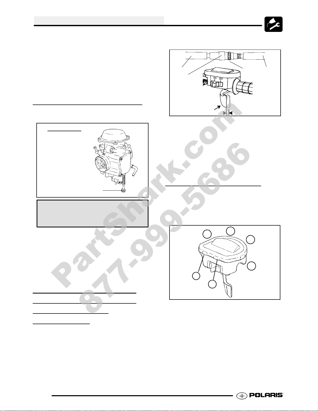
ELECTRONIC THROTTLE
CONTROL (ETC
THROTTLE
CABLE
SWITCH)/
ADJUSTMENT
1. Slide the boots off inline cable adjuster sleeve.
Loosen adjuster locknut.
2. With handlebars centered and wheels pointing
forward, turn adjuster sleeve until 1/16″ -1/8″
freeplay is achieved at the thumb lever. After
making any adjustment, “flip” the lever slightly to
1. Use a medium flat blade screwdriver and insert
blade into the pockets of the cover starting on the
#1 position.
3
6
5
2. Twistscrewdriver slightly while lifting onthecover
to release snap.
3. Repeat procedure at the other five locations as
shown. NOTE: Do not attempt to remove cover
until all latch points are released.
Check for smooth throttle opening and closing in all
handlebar positions. Throttle lever operation should
be smooth and lever must return freely without
binding. Replace the throttle cable if worn, kinked, or
2
1
4
2.16
Page 29
MAINTENANCE
PartShark.com
877-999-5686
damaged.
NOTE: When replacing the cover, check for correct
placement of cover O-ring.
FUEL SYSTEM
WARNING
Gasoline is extremely flammable and explosive
under certain conditions.
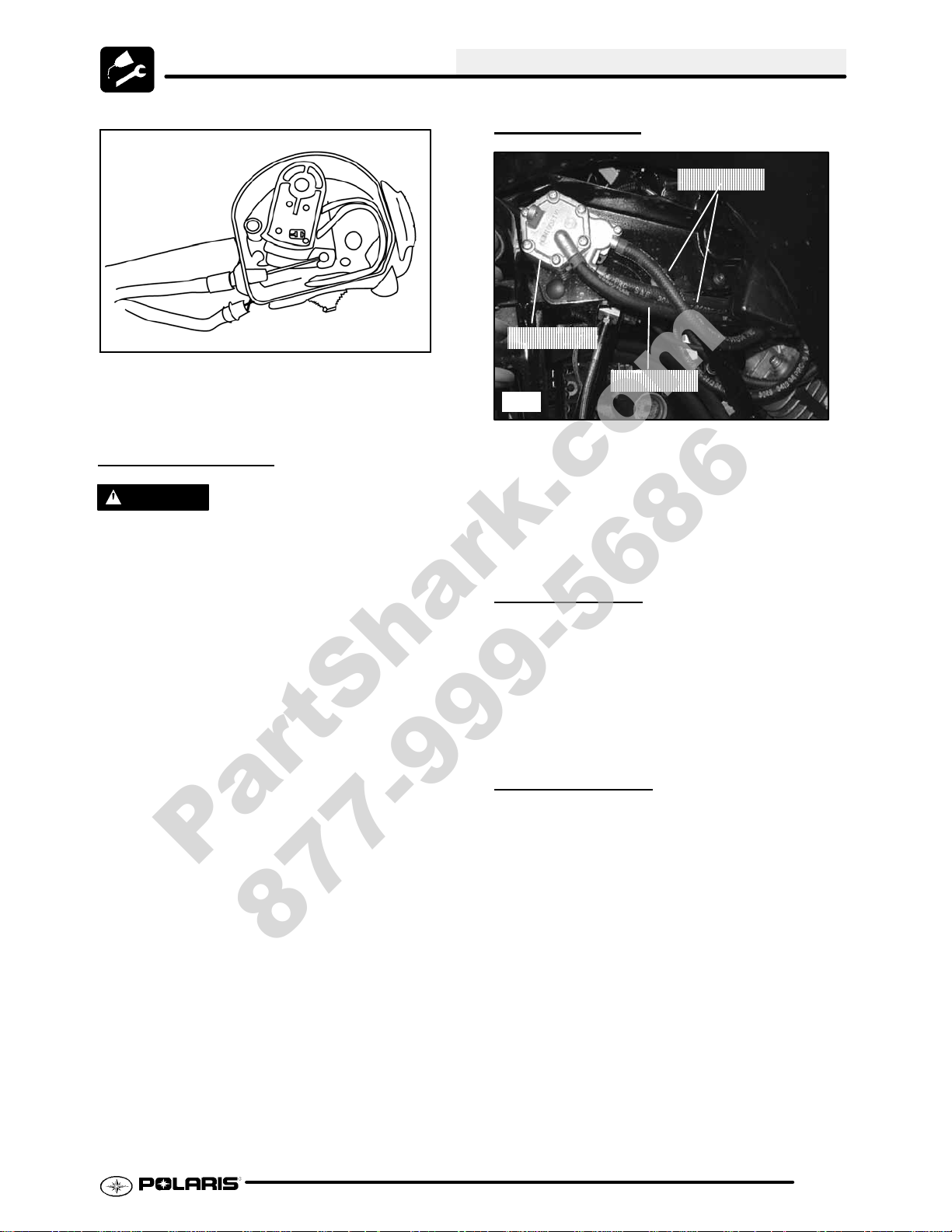
FUEL LINES
Fuel Lines
Fuel Pump
Pulse Line
Ill.1
1. Check fuel lines for signs of wear, deterioration,
damage or leakage. Replace if necessary.
2. Besurefuel linesare routed properly andsecured
with cable ties. CAUTION: Make sure lines are
not kinked or pinched.
3. Replace all fuel lines every two years.
G Always stop the engine and refuel
outdoors or in a well ventilated area.
G Do not smoke or allow open flames
or sparks in or near the area where
refueling is performed or where
gasoline is stored.
G Donot overfill the tank. Donot fill the
tank neck.
G If you get gasoline in your eyes or if
you swallow gasoline, seek medical
attention immediately.
G If you spill gasoline on your skin or
clothing, immediately wash it off with
soapand water and change clothing.
G Never start the engine or let it run in
an enclosed area. Engine exhaust
fumes are poisonous and can result
loss of consciousness or death in a
short time.
G Never drain the float bowl when the
engine is hot. Severe burns may
result.
VENT LINES
1. Check fuel tank, oil tank, carburetor, battery and
transmission vent lines for signs of wear,
deterioration, damage or leakage. Replace every
two years.
2. Be sure vent lines are routed properly and
secured with cable ties. CAUTION: Make sure
lines are not kinked or pinched.
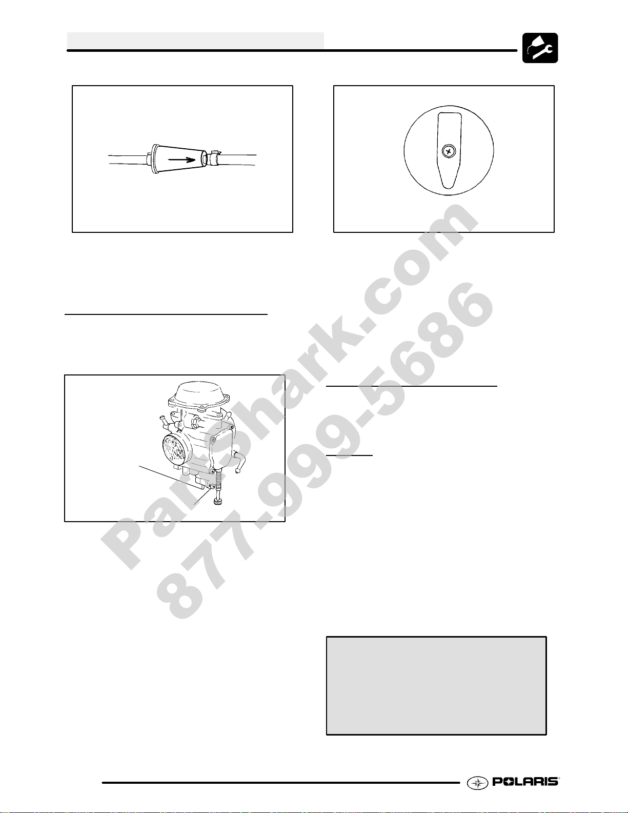
FUEL FILTER
The fuel filter should be replaced in accordance with
the Periodic Maintenance Chart. The fuel filter is
located between the fuel pump and carburetor.
1. Shut off fuel supply at fuel valve.
2. Remove line clamps at both ends of the filter.
3. Remove fuel lines from filter.
4. Install new filter and clamps onto fuel lines with
arrow pointed in direction of fuel flow.
2.17
Page 30
MAINTENANCE
PartShark.com
877-999-5686
Arrow Indicates Direction
of Flow
RES
OFF
To Carburetor
ON
Fuel Valve
5. Install clamps on fuel line.
6. Turn fuel valve ON.
7. Start engine and inspect for leaks.
CARBURETOR DRAINING
The carburetor float bowl should be drained
periodically to remove moisture or sediment from the
bowl, or before extended periods of storage.
Drain tube
attached
here
Drain Screw
NOTE: Thebowl drain screwis located onthebottom
left side of the float bowl.
1. Turn fuel valve to the off position.
2. Place a clean container beneath the bowl drain
spigot or bowl drain hose.
3. Turn drain screw out two turns and allow fuel in
the float bowl and fuel line to drain completely.
4. Inspect the drained fuel for water or sediment.
5. Tighten drain screw.
6. Turnfuelvalveto“ON”.
7. Start machine and check for leaks.
NOTE: If there is a tube attached, it must be
reattached as this will effect engine performance.
COMPRESSION TEST
NOTE: This Polaris 4-Strokeengine is equipped with
an automatic decompressor. Compression readings
will vary in proportion to cranking speed during the
test. Average compression (measured) is about
70--90 psi
Smooth idle generally indicates good compression.
Low engine compression is rarely a factor in running
condition problems above idle speed. Abnormally
high compression can be caused by a decompressor
malfunction, or worn or damaged exhaust cam lobes.
Inspect camshaft and automatic decompression
mechanism if compression is abnormally high.
A cylinder leakage test isthe best indication ofengine
condition on models with automatic decompression.
Follow tester manufacturer’s instructions to perform
a cylinder leakage test. (Never use high pressure
leakagetesters ascrankshaft seals may dislodgeand
leak).
during a compression test.
Cylinder Compression
Standard 70--90 PSI
Cylinder Leakage
Service Limit: 10 %
(Inspect for cause if leakage exceeds 10%)
2.18
Page 31

MAINTENANCE
PartShark.com
877-999-5686
ENGINE MOUNTS
Inspect rubber engine mounts for cracks or damage.
ENGINE FASTENER TORQUE
Check engine fasteners and ensure they are tight.
BATTERY MAINTENANCE
WARNING
Battery electrolyte ispoisonous. Itcontains
sulfuric acid. Serious burnscanresultfrom
contact with skin, eyes or clothing. Antidote:
External: Flush with water.
Internal: Drink large quantities of water or
milk. Follow with milk of magnesia, beaten
egg, or vegetable oil. Call physician immediately.
Eyes: Flush with water for 15 minutes and
get prompt medical attention.
Batteries produce explosive gases. Keep
sparks, flame, cigarettes, etc. away. Ventilate when charging or using in an enclosed
space. Always shield eyes when working
nearbatteries. KEEPOUTOF REACH OF
CHILDREN.
NOTE: All Trail Boss ATV batteries are
Maintenance -- Free design and construction. All
Maintenance--Free batteries arefully chargedand
tested at the factory before installation. Expected
shelf life is 6 --8 months depending on storage
conditions. As a general rule before placing the
battery into service, check the battery condition
and charge accordingly .
Maintenance -- Free batteries are permanently
sealed at the time of manufacture. The use of
lead--calcium and AGM technology instead of
lead--antimony allows the battery acid to be fully
absorbed. For this reason, a Maintenance--Free
battery case is dark and the cell caps are not
removable, since there is no need to check
electrolyte level.
NEVER attempt to add electrolyte or water to a
Maintena nc e--Free battery. Doing so will damage
the case and shorten the life of the battery. Refer
to the Battery Maintenance Video (PN 9917987) for
proper instruc tion on serv ic ing Maintenance--Free
batteries.
The battery is located under the left rear fender.
B
A
Battery
To remove the battery:
1. Disconnect holder strap (A) and remove cover
(B).
2. Disconnect battery negative (-)(black) cablefirst,
followed by the positive (+) (red) cable.
CAUTION
To reduce the chance of sparks: Whenever
removing the battery, disconnect the negative
(black) cable first. When reinstalling the battery,
install the negative cable last.
3. Remove the battery.
4. Cleanbatterycables andterminalswitha stiffwire
brush. Corrosion can be removed using a
solution of one cup water and one tablespoon
baking soda. Rinse well with clean water and dry
thoroughly.
5. Reinstallbattery,attaching positive(+)(red) cable
first and then the negative (-) (black) cable.
6. Coat terminals and bolt threads with Dielectric
Grease (PN 2871329).
7. Reinstall battery cover and holder strap.
2.19
Page 32

MAINTENANCE
PartShark.com
877-999-5686
SPARK PLUG
330 Engine
A
1. Removespark plug hightension lead. Cleanplug
area so no dirt and debris can fall into engine
when plug is removed.
2. Remove spark plug.
3. Inspect electrodes for wear and carbon buildup.
Look for a sharp outer edge with no rounding or
erosion of the electrodes.
Inpsect electrode for
wear and buildup
Recommended Spark Plug:
NGK BKR6E
Spark Plug Torque: 9--11 Ft. Lbs.
(12--14 Nm)
IGNITION TIMING
Refer to Electrical chapter for ignition timing
procedure.
Ignition Timing:
30°±2° BTDC@5000RPM
ENGINE-TO-FRAME GROUND
Inspect engine-to-frame groundcableconnection. Be
sure it is clean and tight.
Engine Ground Strap
4. Clean with electrical contact cleaner or a glass
bead spark plugcleaner only. CAUTION: A wire
brush or coated abrasive should not be used.
5. Measure gap with a wire gauge. Refer to
specifications for proper spark plug type andgap.
Adjust gap if necessary by bending the side
electrode carefully.
MAIN AIR FILTER CLEANING
Spark Plug Gap
.036″ (.9 mm)
6. If necessary,replacespark plug with proper type.
CAUTION: Severe engine damage may occur if
the incorrect spark plug is used.
7. Apply a small amount of anti-seize compound to
the spark plug threads.
8. Installsparkplug andtorqueto 9--11ft. lbs(12--14
Nm).
It is advisable to replace the filter when it is dirty.
However, in an emergency it is permissible to clean
the main filter if you observe the following practices.
G Never immerse the filter in water
since dirt can be transferred to the
clean air side of the filter.
G If compressed air is used never
exceedapressureof 40PSI. Always
use a dispersion type nozzle to
prevent filter damageand clean from
the inside to the outside.
2.20
Page 33

MAINTENANCE
PartShark.com
877-999-5686
G Replace the air filter every 50 hours,
and possibly more often in very dirty
conditions.
AIR FILTER/PRE-FILTER
SER
It is recommended that the air filter and pre filter be
replaced annually. When riding in extremely dusty
conditions, replacement is required more often.
Theprefiltershould becleanedbeforeeachrideusing
the following procedure:
1. Lift up on the rear of the seat.
2. Pull the seat back and free of the tabs. NOTE:
3. Remove clips from air box cover (A) and remove
VICE
When reinstalling seat, make sure the slots in the
seat engage the tabs in the fuel tank.
cover. Inspect the gasket (E). It should adhere
tightly to the cover and seal all the way around.
8. Inspect main filter and replace if necessary . If the
filter has been soaked with fuel or oil it must be
replaced.
Installation:
9. Reinstall pre-filter element over main filter. Be
sure the element covers entire surface of main
filter without folds, creases, or gaps.
10. Reinstall filter on main filter mount. Place filter
clamp over the assembly and tighten.
NOTE: Apply a small amount of general purpose
grease to the sealing edges of the filter before
reinstalling.
Filter Clamp
A
4. Loosenclamp andremoveair filter assembly (B&
C).
C
B
Ill.1
Cleaning:
5. Slipthe pre-filter element (C) off of main element.
Clean the pre filter with hot soapy water.
6. Rinse and dry thoroughly.
7. Inspect element for tears or damage.
A
E
ILL.1
Proper Filter Placement
Filter Support
Air Box
Ill.3
NOTE: The air filter should rest on the filter support.
Proper placement of the air filter is important to
prevent rattles and air leaks. See Illustration above.
1 1. Install air box cover and secure with clips.
Main Filter
Front
2.21
Page 34

MAINTENANCE
PartShark.com
877-999-5686
AIR BOX SEDIMENT TUBE
Periodically check the air box drain tube located
toward the rear of the machine. Drain whenever
deposits are visible in the clear tube.
Sediment Tube
NOTE: Thesediment tube willrequire morefrequent
service if the vehicle is operated in wet conditions or
at high throttle openings for extended periods.
1. Remove drain plug from end of sediment tube.
2. Drain tube.
3. Reinstall drain plug.
RECOIL HOUSING
G Drain the housing periodically to
remove moisture.
recoil housing, especially when
travelling in wet areas. If it is not
sealed properly, water may enter the
recoil housing and damage
components.
G Water will enter the recoil housing if
the starter handle (B) is disengaged
from the rope guide when under
water.
G After travelling in wet areas, the
recoil housing and starter should
always be drained completely by
removing the recoil.
G Do not open the crankcase drain
unless the engine has ingested
water. Some engine oil will be lost if
crankcase drain is opened.
G If recoil handle seal has been
damaged, the handle assembly
should be replaced.
PVT DRAIN PLUG & DRYING
NOTE: If operating the ATV in or through water, be
sure to check the PVT cover and other components
for water ingestion. The A TV should be checked
immediately.
1. To release any water that maybe trapped in the
PVTcover,simplyremovethe PVTdrainplugand
O--ring located on the bottom of the PVT cover
and let the water drain out. The PVT drain plug is
shown below.
B
Recoil Drain
G Drain the recoil housing after
operating the ATV in very wet
conditions. Thisshould also be done
before storing the ATV. The drain
screw is located at the bottom of the
recoil housing. Remove the screw
with a 10mm wrench. Reinstall
screw once housing has been
drained.
G CAUTION: Make sure the manual
start handle (B) is fully seated on the
Ill.3
2. To further expel water from the cover and to dry
out the PVT system, shift the transmission to
neutral and rev engine slightly to expel the
moisture and air-dry the belt and clutches. Allow
engine RPM to settle to idle speed, shift
transmission to lowest available range and test
for belt slippage. OperateATVin lowestavailable
range for a short period of time until PVT system
is dry.
PVT Drain Plug & O--ring
2.22
Page 35

MAINTENANCE
PartShark.com
877-999-5686
ENGINE OIL LEVEL
To check the oil level:
1. Set machine on a level surface.
2. Start and run engine for 20-30 seconds. This will
return oil to its true level in the engine sump.
3. Stop engine, remove dipstick and wipe dry with a
clean cloth.
4. Reinstall dipstick, screwing into place.
5. The dipstick must be screwed completely in to
ensure accurate measurement.
6. Remove dipstick and check to see that the oil
level is in the normal range. The oil should be
between the top of thebottom crosshatched area
andthebottomof thetop crosshatchedarea. Add
oilas indicated by thelevel onthe dipstick. Donot
overfill.
Normal Oil Operating
Range is between crosshatch.
OIL AND FILTER CHANGE
1. Place vehicle on a level surface.
2. Cleanarea around drain plug at bottomof oil pan.
3. Runenginetwoto three minutes until warm. Stop
engine.
4. Place a drain pan beneath oil pan and remove
drain plug from under the crankcase. CAUTION:
Oil may be hot. Do not allow hot oil to come into
contact with skin as serious burns may result.
5. Allow oil to drain completely.
NOTE: It is not necessary to drain the oil from the oil
cooler, unless contaminants, water, or debris are
found in the crankcase oil.
6. Replacesealingwasher(A)ondrainplug. NOTE:
The sealing surfaces on drain plug and oil tank
should be clean and free of burrs, nicks or
scratches.
7. Reinstall drain plug and torque to 14 ft. lbs. (19
Nm).
Crosshatch Areas of Dipstick
NOTE: Do not fill the over the normal oil operating
range. Filling over the normal operating range could
cause a mist of oil to enter the air box.
Drain plug located under the engine.
NOTE: Rising oil level between checks in cool
weatherdriving, canindicatemoisture collectinginthe
oil reservoir. If the oil level is over the full mark,
change the oil.
Recommended Engine Oil:
Polaris Premium 4 All Season
Synthetic, 2W--50
Engine Sump Drain Plug - Bottom View
8. The oil filter is located on the right side of the
machine. Place shop towels beneath oil filter.
Crankcase Drain
2.23
Page 36

MAINTENANCE
PartShark.com
877-999-5686
Using an oil filter wrench, turn filter
counterclockwise to remove.
Filter
9. Usingacleandry cloth,cleanfilter sealingsurface
on crankcase.
10. Lubricate O-ring on new filter with afilm ofengine
oil. Check to make sure the O-ring is in good
condition.
1 1. Install newfilterand turnby handuntilfiltergasket
contacts the sealing surface, then turn and
additional 1/2 turn.
VALVE CLEARANCE
Inspect and adjust valve clearance while the engine
is cold and the piston positioned at Top Dead Center
(TDC) on compression stroke.
1. Remove the seat.
2. Remove body panels and fuel tank as necessary
to gain access to valve cover.
3. Remove the spark plug high tension lead and
remove thesparkplug. CAUTION: Placea clean
shop towel into the spark plug cavity to prevent
dirt from entering.
4. Remove plastic valve plugs.
330 V alve Plugs
NOTE: The sealing surfaces on the drain plug and
crankcase should be clean and free of burrs, nicks or
scratches.
12. Remove dipstick and fill tank with 2 quarts (1.9 l)
ofPolarisPremium4 SyntheticOil (PN2871281).
13. Place gear selector in neutral and set parking
brake.
14. Start the engine and let it idle for one to two
minutes. Stop the engine and inspect for leaks.
15. Re-check the oil level on the dipstick and add oil
as necessary to bring the level to the upper mark
on the dipstick.
16. Dispose of used filter and oil properly.
Crankcase Drain Plug Torque:
14 ft. lb s. (19 Nm)
Oil Filter Torque:
Turn by hand until filter gasket
contacts sealing surface, then
turn an additional 1/2 turn
Oil Filter Wrench:
(PV--43527)
5. Remove timing inspection plug from recoil
housing.
CAUTION: Failure to position the crankshaft at TDC
on compression stroke will result in improper valve
adjustment.
6. Rotate engine slowly with recoil rope, watching
the intake valve(s) open and close.
NOTE: Observe the intake valve closing and then
start toopen, continueto rotate until the“T” aligns with
pointer. The camshaft lobes should be pointing
downward.
7. V erifyaccurate TDC positioning by observing the
“T” mark aligned with the pointer in the timing
inspection hole. In this position there should be
clearance on all valves.
INTAKE VALVE CLEARANCE:
0.006±0.0008I (0.15±0.02 mm)
BTDC on compression
2.24
Page 37

INTAKE VALVE CLEARANCE
PartShark.com
877-999-5686
ADJUSTMENT
1. Insert a .006″ (.15mm) feelergauge betweenend
of intake valve stem and clearance adjuster
screw.
2. Using Valve/Clutch Adjuster (PA--44689), loosen
adjuster lock nut and turn adjusting knob until
there is a slight drag on the feeler gauge.
330 Engine
MAINTENANCE
1. Insert.006″ feelergauge between end of exhaust
valve stem and adjuster screw.
EXHAUST VALVE CLEARANCE:
0.006±0.0008I (0.15±0.02 mm)
BTDC on compression
2. Loosenlocknutandturnadjusterscrew untilthere
is a slight drag on feeler gauge.
3. When clearance is correct, hold adjuster screw
and tighten locknut securely
4. Re-check the valve clearance.
5. Repeat adjustment procedure if necessary until
clearance is correct with locknut secured.
6. Inspect o-rings on the plastic valve plugs, replace
if damaged. Securely fasten valve plugs.
7. Reinstallfuel tank and any body panels that were
removed to gain access.
STEERING
The steering components should be checked
periodicallyfor loose fasteners, worn tierod ends,and
damage. Also check to make sure all cotter pins are
in place. If cotter pins are removed, they must not be
re-used. Always use new cotter pins.
Replace any worn or damaged steering components.
Steering should move freely through entire range of
travel without binding. Check routing of all cables,
hoses, and wiring to be sure the steering mechanism
isnotrestricted orlimited. NOTE: Whenever steering
components are replaced, checkfront endalignment.
Use only genuine Polaris parts.
WARNING
NOTE: Due to the critical nature of the procedures
outlined in this chapter,Polaris recommends steering
componentrepair andadjustment beperformedbyan
3. Holdadjuster screw and tighten adjuster lock nut
securely.
4. Re-check the valve clearance.
5. Repeat adjustment procedure if necessary until
clearance is correct with locknut secured.
authorized Polaris Dealer. Onlya qualifiedtechnician
should replace worn or damaged steering parts. Use
only genuine Polaris replacement parts.
One of two methods can be used to measure toe
alignment: The string method and the chalk method.
If adjustment is required, refer to following pages for
procedure.
EXHAUST VALVE
CLEARANCE
NOTE: Theexhaust valveis adjustedthesameasthe
intake valve.
ADJUSTMENT
2.25
Page 38

MAINTENANCE
PartShark.com
877-999-5686
TIE ROD END / STEERING
INSPECTION
To check for play inthetie rod end, grasp the steering
tie rod, pull in all directions feeling for movement.
G Repeat inspection for inner tie rod
end (on steering post).
G Replace any worn steering
components. Steering should move
freely through entire range of travel
without binding.
G If abnormal movement is detected,
inspect the hub and wheel assembly
to determine the cause.
G Refer to the Body/Steering or Final
Drive chapter for more information.
CAMBER AND CASTER
The camber and caster are non-adjustable.
WHEEL ALIGNMENT METHOD:
STRAIGHTEDGE OR
Be sure to keep handlebars centered. See notes
below.
NOTE: String should just touch side surface of rear tire on each side of machine.
STRING
G Elevate front end of machine so front
wheels are off the ground. Checkfor
any looseness in front hub / wheel
assembly by grasping the tire firmly
at top and bottom first, and then at
front andrear. Try to movethewheel
and hub by pushing inward and
pulling outward.
Check for Loose Wheel or Hub
Measure
from string
to rim at
front and
rear of rim.
NOTE: Thesteeringpostarmcanbeused
as an indicator of whether the handlebars
are straight. The frog should always point
straight back from the steering post.
Rear rim
measure-
ment should
be 1/16″ to
1/8″ (.2to.3
cm) more
than front rim
measure-
ment.
2.26
Page 39

MAINTENANCE
PartShark.com
877-999-5686
WHEEL ALIGNMENT
METHOD 2:
1. Place machine on a smooth level surface.
2. Set handlebars in a straight ahead position and
secure handlebars in this position. NOTE: The
steeringarmcanbeusedasanindicatorof
whether the handlebars are straight. The arm
should always point straight back from the
steering post.
3. Place a chalk mark on the center line of the front
tires approximately 10″ (25.4 cm) fromthe floor or
as close to the hub/axle center line as possible.
NOTE: It is important that the height of both
marks be equally positioned in order to get an
accurate measurement.
4. Measure the distance between the marks and
record the measurement. Callthis measurement
“A”.
5. Rotatethetires180° bymovingvehicle forwardor
backward. Position chalkmarks facing rearward,
even with the hub/axle centerline.
6. Again measure the distance between the marks
and record. Callthis measurement “B”. Subtract
measurement “B” from measurement “A”. The
difference between measurements “A” and “B” is
the vehicle toe alignment. The recommended
vehicle toe tolerance is 1/8″ to 1/4″ (.3to.6cm)
toeout. This means themeasurementat the front
ofthe tire (A)is 1/8″ to 1/4″ (.3to .6 cm)wider than
the measurement at the rear (B).
CHALK
TOE ALIGNMENT
ADJUSTMENT
If toe alignment is incorrect, measure the distance
between vehicle center and each wheel. This will tell
you which tie rod needs adjusting. NOTE: Be sure
handlebars are straight ahead before determining
which tie rod(s) need adjustment.
CAUTION: During tie rod adjustment it is very
important that the following precautions be taken
when tightening tie rod end jam nuts. If the rod end
is positioned incorrectly it will not pivot, and may
break.
To adjust toe
G Hold tie rod end to keep it from
G Loosenjamnuts atbothendof thetie
G Shorten or lengthen the tie rod until
G Important: When tightening the tie
alignment:
rotating.
rod.
alignmentisasrequir ed to achieve
the proper t oe set ting. M ethod 1
(1/16″ to 1/8″)or Method 2 (1/8″ to
1/4″).
rod end jam nuts, the rod ends must
be held parallel to prevent rod end
damage and premature wear.
Damage may not be immediately
apparent if done incorrectly. See
illustration.
Hold
Rod End
Correctly
Tightened
Jam Nut
Chalk Line
Measurement
“A”
Measurement “B”
Incorrectly
Tightened
Jam Nut
2.27
Page 40

MAINTENANCE
PartShark.com
877-999-5686
EXHAUST CLEANING
WARNING
G Do not perform clean out immediately
after the engine has been run, as the exhaust system becomes very hot. Serious
burns could result from contact with exhaust components.
G T o reduce fire hazard, make sure that
there are no combustible materials in the
area when purging the spark arrestor.
G Wear eye protection.
G Do not stand behind or in front of the ve-
hicle while purging the carbon from the
spark arrestor.
G Never run the engine in an enclosed
area. Exhaust contains poisonous carbon monoxide gas.
G Do not go under the machine while it is
inclined. Set the hand brake and block
the wheels to prevent roll back.
Failure to heed these warnings could result in
serious personal injury or death.
The exhaust pipe must be periodically purged of
accumulated carbon as follows:
1. Remove the clean out plugs located on the
bottom of the muffler as shown in illustration 1.
3. If some carbon is expelled, cover the exhaust
outlet and lightly tap on the pipearound the clean
out plugs while revving the engine several more
times.
4. If particles are still suspected to be in the muffler,
backthe machineonto an inclineso therear of the
machine is one foot higher thanthe front. Set the
hand brake and block the wheels. Make sure the
machine is in neutral and repeat Steps 2 and 3.
SEE WARNING ABOVE
5. If particles are still suspected to be in the muffler,
drive the machine onto the incline so the front of
the machine is one foot higher than the rear. Set
the hand brake and block the wheels. Makesure
the machine is in neutral and repeat Steps 2 and
3. SEE PREVIOUS WARNING
6. Repeat Steps 2 through 5 until no more particles
are expelled when the engine is revved.
7. Stop the engine and allow the arrestor to cool.
8. Reinstall the clean out plugs.
BRAKE SYSTEM INSPECTION
The following checks are recommended to keep the
brakesystemin goodoperating condition. Service life
of brake system components depends on operating
conditions. Inspect brakes in accordance with the
Ill.1
2. Place the transmission in neutral and start the
engine. Purge accumulated carbon from the
system by momentarily revving the engine
several times.
Clean Out Plug
maintenance schedule and before each ride.
G Keepfluidlevel inthe master cylinder
reservoir to the indicated level inside
reservoir.
G Use Polaris DOT 4 Brake Fluid
(PN 2872189).
2.28
Page 41

MAINTENANCE
PartShark.com
877-999-5686
Sight
Glass
Auxiliary Brake
Master Cylinder
G Check brake system for fluid leaks,
excessive travel or spongy feel.
G Check friction pads for wear,
damage or looseness.
G Check surface condition of the disc.
G Inspect thickness of brake pad
frictionmaterial.
Parking Brake
Lock
BRAKE PAD INSPECTION
AUXILIARY BRAKE
ADJUSTMENT
Use the following procedure to inspect the hydraulic
auxiliary (foot) brake system and adjust or bleed if
necessary:
First, checkfootbrake effectiveness byapplying50lb.
(approx.) downwardforce onthe pedal. The top of the
pedal should be at least 1 inch, (25.4mm) above the
surface of the footrest.
1/8, to 1/4,
Free Play
If less than one inch, two things must be examined:
Free Play:
Free play of the brake pedal should be 1/8 - 1/4
inch (3.2 - 6.35 mm).
If free play is excessive, inspect pedal, linkage, and
master cylinder for wear or damage and replace any
parts as needed.
Bleeding:
(HYDRAULIC)
50 lbs
1″ or greater
Floorboard
If free play is correct and brake pedal travel is still
excessive, air may be trapped somewhere in the
system. Bleed the hydraulic auxiliarybrakesystem in
a conventional manner, following the procedure
outlined in Brake Chapter 9.
DRIVE CHAIN AND
3/64″
(.1cm)
Minimum
Thickness
Pads should be changed when friction material is
wornto3/64″ (.1cm), orabout thethicknessof adime.
HOSE/FITTING INSPECTION
Check brake system hoses and fittings for cracks,
deterioration, abrasion, and leaks. Tighten any loose
fittings and replace any worn or damaged parts.
SPROCKET
Polaris ATV drive chains are equipped with O-ring
sealed permanently greased pins and rollers. The
sprockets and outer rollers require periodic
lubrication. Lubricate the chain with Polaris O-Ring
Chain Lubricant (PN 2872073).
Inspect the drive chain for missing or damaged
O-Rings, link plates, or rollers. Donotwashthechain
with a high pressure washer, gasoline or solvents; do
not use a wire brush to clean the chain as damage to
the O-Rings may occur. Clean chain with hot soapy
water and a soft bristled nylon brush.
INSPECTION
2.29
Page 42

MAINTENANCE
PartShark.com
877-999-5686
Never allow battery acid to contact the drive chain.
Service Limit:
1/4″ (6mm)
Proper
Splicelink Clip
Opening
Position
Drive Chain Wear Limit-- 20 Pitch Length:
Std: 12.5″ (32 cm)
Wear Limit: 12.875″ (32.7 cm)
Drive Chain Lubricant:
Polaris O-Ring Chain Lubricant
(PN 2872073)
SPROCKET INSPECTION
Inspect the sprocket for worn, broken or bent teeth.
To check for wear, pull outward on the chain as
shown. Replacesprocket if chainmovementexceeds
1/4″ (.6 cm).
DRIVE CHAIN INSPECTION
The chain must be replaced when it reaches 3%
elongation.
1. Stretch the chain tightly in a straight line.
2. Measurealength oftwentypitches(pins) from pin
center to pin center, and compare to the
specification. Replace the chain if the length
exceeds the wear limit.
3. When replacing or reinstalling drive chain, install
theclosed end ofthe splicelink clipasshown,with
the closed end leading in forward operation.
DRIVE CHAIN ADJUSTMENT,
CONCENTRIC
CAUTION: Never adjust or operate the vehicle
with the rear drive chain too loose or too tight as
severe damage to the transmission and drive
components can result.
Break-In: Itis extremely importantto maintain proper
chain tension to ensure the best possible chain life.
There is a chain break-in period of approximately 100
miles or two (2) tanks of fuel. During this time chain
tension should be watched very closely and loads to
the chain should be kept light.
Checking Deflection: Inspect chain deflection by
slowly moving theATV forward so any slack that may
have previously been on the under part of the chain
is now on the top side of the chain. The bottom part
of the chain should be taught during inspection.
Measure the chain deflection as shown in the
diagram. Deflection should be approximately3/8
in. (10 mm).
After inspection, again slowly move the ATV forward
until all the chain slack is on the top side of the chain
and inspect the deflection. Repeat this procedure
several times to check different spots on the chain.
SWINGARM
The chain is correctly adjusted when the tightest
portion of the chain itself has approximately 3/8 in.,
(10 mm) of deflection. It’s a common characteristic of
2.30
Page 43

MAINTENANCE
PartShark.com
877-999-5686
anychain to have oneor moretight spotsin thechain.
Therefore, it is extremely important to check chain
deflection in several areas of the chain to ensure
deflection is correct at the tightest point.
2. Loosen two eccentric clamp bolts.
3. 2004 Models -- Loosen caliper mounting bracket
bolts.
4. Using a 2 1/2″ wrench, rotate the housing to
adjust chain slack to the proper dimension, and
then proceed to Step 7; or... follow Steps 5 and
6 for alternate method if 2 1/2″ wrench is not
available.
Loosen
Tighten
5. Insert a pin punch through the sprocket hub and
into the eccentric axle housing.
3/8″ (10 mm) Deflection
ADJUSTMENT PROCEDURE CONCENTRIC
REAR
AXLE
Loosen (2) caliper
mounting bracket
bolts (Step 3 --
2004 models)
SWINGARM
Loosen Eccentric
clamp bolts (Step 2)
Alternate Adjustment Method -- Pin Punch
(Step 5 and 6)
6. Roll the vehicle ahead or back to adjust chain
slack to the proper dimension.
7. Tightenthe eccentric clampbolts tospecification.
CAUTION: DO NOT OVER-TIGHTEN
ECCENTRIC CLAMP BOLTS. PREMATURE
BEARING FAILURE MAY RESULT.
Eccentric Clamp Bolt Torque Specs
Pinch Clamp Bolt Torque --
30 ft. lb s. (41 Nm)
Pinch Clamp Bolt Torque
w/ Trailer Hitch -- 40 ft. lbs. (54 Nm)
1. Loosen chain guard.
2.31
Page 44

MAINTENANCE
PartShark.com
877-999-5686
Eccentric Clamp Without Hitch
30 ft.lbs. (41 Nm)
Without Trailer Hitch
Eccentric Clamp With Hitch
chain has approximately 3/8 in. (10 mm) of
deflection.
1 1. Reinstall the chain guard (where applicable).
Reposition chain guide to allow 1/8″ (.3 cm)
clearance between sprocket and guide.
Chain Guide
SUSPENSION SPRING
PRELOAD
ADJUSTMENT
Torque to 40 ft.lbs. (54 Nm)
With Trailer Hitch
8. Remove the pin punch.
9. 2004 Models -- Tighten caliper mounting bracket
bolts 10-12 ft. lbs. (14 - 17 Nm).
2004 Models: Caliper Mount Bracket
10-12 ft. lbs
Operator weight and vehicle loading affect
suspension spring preload requirements. Adjust as
necessary to avoid bottoming of the shocks.
FRONT SUSPENSION
Compress and release front suspension. Damping
should be smooth throughout the range of travel.
Check all front suspension components for wear or
damage.
Inspect front strut cartridges for leakage.
REAR SUSPENSION
Compress and release rear suspension. Damping
should be smooth throughout the range of travel.
Rear Spring
Adjustment Ring
10. Verify chain adjustment is correct after tightening
eccentric clamp bolts to specification by rolling
ATV forward and checking chain tension in
several places on chain. The chain is adjusted
correctly when the tightest portion of the
G Check all rear suspension
components for wear or damage.
G Inspect shock for leakage.
2.32
Page 45

Shock Spanner Wrench
PartShark.com
877-999-5686
(PN 2870872)
CONTROLS
Check controls for proper oper ation, posit ioning
and adjustment .
MAINTENANCE
WHEEL REMOVAL FRONT OR
REAR
1. Stop the engine, place the transmission in gear
and lock the parking brake.
2. Loosen the wheel nuts slightly.
3. Elevate the side of the vehicle by placing a
suitable stand under the footrest frame.
4. Remove the wheel nuts and remove the wheel.
Front Wheel
Front Wheel Nuts (4)
27 ft. lbs. (37 Nm)
Front Spindle Nut
40 ft. lbs. (54 Nm)
G Brake control and switch must be
positioned to allow brake lever to
travel throughout entire range
without contacting switch body.
WHEELS
Inspect all wheelsfor runout or damage. Checkwheel
nuts and ensure they aretight. Donot over tightenthe
wheel nuts.
WHEEL, HUB, AND SPINDLE
TORQUE T
Item Specification
Front Wheel Nuts 27 Ft. lbs. (37 Nm)
Rear Wheel Nuts 50 Ft. Lbs. (68 Nm)
Front Spindle Nut 40 Ft Lbs. (54Nm)
Rear Hub Retaining Nut 80 Ft. Lbs. (108 Nm)
ABLE
Rear Wheel
Rear Wheel Nuts (4)
50 ft. lbs. (68 Nm)
Taper end faces
wheel for install.
Rear Hub Nut
80 ft. lbs. (108 Nm)
WHEEL INSTALLATION
1. With the transmission in gear and the parking
brake locked, place the wheel in the correct
positiononthewheelhub. Besure thevalvestem
is toward the outside and rotation arrows on the
tire point toward forward rotation.
2. Attach the wheel nuts and finger tighten them.
NOTE: Install the tapered end of the rear wheel nut
goes into the taper of the wheel. See illustration
above.
2.33
Page 46

MAINTENANCE
PartShark.com
877-999-5686
3. Lower the vehicle to the ground.
4. Securely tighten the wheel nuts to the proper
torque listed in the table.
CAUTION:
If wheels are improperly installed it could affect
vehicle handling and tire wear. Be sure to properly
torque and install all wheel nuts.
TIRE PRESSURE
Tire Pressure Inspection (PSI - Cold)
Front Rear
4 3
TIRE INSPECTION
Tread
Depth 1/8I (3 mm)
FRAME, NUTS, BOLTS,
ASTENERS
F
Periodically inspect the tightness of all fasteners in
accordance with the maintenance schedule. Check
that all cotter pins are in place. Refer to specific
fastener torques listed in each chapter.
WARNING
Operating anATVwithworn tires will increase
the possibility of the vehicleskidding and possible loss of control.
Worn tires can cause an accident.
Always replace tires when the tread depth
measures 1/8″ (.3 cm) or less.
CAUTION:
G Maintain proper tire pressure. Refer
to the warning tire pressure decal
applied to the vehicle.
G Impropertire inflationmayaffect ATV
maneuverability.
G When replacing a tire always use
original equipment size and type.
G Theuseof non-standard size or type
tires may affect ATV handling.
Tire Tread Depth
Always replace t ires when tread depth is worn to
1/8″ (3 mm) or less.
2.34
Page 47

Engine Service Data 3.2-3.3.........................
PartShark.com
877-999-5686
Special Tools and Torque Specifications 3.4........
Torque Patterns 3.4.............................
Piston Identification 3.5..........................
Engine Removal 3.5............................
Engine Installation Notes 3.6.....................
Cylinder Honing 3.6-3.7.............................
Engine Lubrication 3.7...........................
Oil Pressure Test 3.7-3.8............................
Lubrication/Oil Flow 3.8-3.9..........................
Engine Exploded View 3.10.......................
Engine Top End Disassembly 3.11 -3.18.................
Valve/ Valve Seat Service 3.18-3.22....................
Engine Bottom End Disassembly 3.22-3.32..............
Crankcase & Bearing Assembly 3.32...............
Crankshaft End Play Inspection 3.32-3.33...............
Engine Assembly/Inspection/Adjustments 3.33-3.43......
Recoil Disassembly/Inspection/Reassembly 3.44-3.45....
Spark Plug Fouling Checklist 3.46..................
Troubleshooting 3.46-3.47.............................
ENGINE
3.1
Page 48

ENGINE
g
j
j
y
g
g
g
pgg
PartShark.com
877-999-5686
ES32PFE10 ENGINE SERVICE DAT
Cylinder Head / Valve ES32PFE10
Rocker Arm
Camshaft Cam lobe height In
Cylinder Head
Valve Seat Contacting width In
Valve Guide
Valve Margin thickness In
Valve
Valve Spring Free length
Rocker arm ID .8669-.8678″ (22.020-22.041 mm)
Rocker shaft OD .8656-.8661″ (21.987-22.0 mm)
Rocker shaft Oil Clearance
Camshaft journal OD
Camshaft journal bore ID
Camshaft Oil clearance
Surface warpage limit .0020″ (.05 mm)
Standard height 2.908″ (73.8 mm)
Inner diameter .2362-.2367″ (6.000-6.012 mm)
Protrusion above head .681-.689″ (17.3-17.5 mm)
Stem diameter In .2343-.2348″ (5.950-5.965 mm)
Stem oil clearance Std
Overall length
Squareness 0.075″ (1.9 mm)
Std .0008-.0021″ (.020-.054 mm)
Limit .0039″ (.10 mm)
Std 1.3001--1.3041″ (33.023-33.123 mm)
Limit 1.2883″ (32.723 mm)
Ex
Std 1.3007-1.3047″ (33.039-33.139 mm)
Limit 1.2889″ (32.739 mm)
Mag 1.4935-1.4941″ (37.935-37.950 mm)
PTO 1.4935-1.4941″ (37.935-37.950 mm)
Mag 1.4963-1.4970″ (38.005-38.025 mm)
PTO 1.4963-1.4970″ (38.005-38.025 mm)
Std .0022-.0035″ (.055-.090 mm)
Limit .0039″ (.10 mm)
Std .039″ (1.0 mm)
Limit .055″ (1.4 mm)
Ex
Std .059″ (1.5 mm)
Limit .071″ (1.8 mm)
Std .039″ (1.0 mm)
Limit .032″ (0.8 mm)
Ex
Std .047″ (1.2 mm)
Limit .032″ (0.8 mm)
Ex .2341-.2346″ (5.945-5.960 mm)
In 0.0014-0.0024″ (0.035-0.062mm)
Ex 0.0016-0.0026″ (0.040-0.067mm)
Limit .0059″ (0.15 mm)
In 3.979″ (101.0 mm)
Ex 3.987″ (101.2 mm)
Std 1.673″ (42.5 mm)
Limit -- -- --
A
3.2
Page 49

ENGINE
gggpp
g
g
g
p
g
g
g
g
g
ggg
PartShark.com
877-999-5686
ES32PFE10 ENGINE SERVICE DAT
Cylinder / Piston / Connecting Rod ES32PFE10
Cylinder
Piston Outer diameter
Piston Pin
Piston Ring Piston ring installed gap Top ring
Piston Ring Standard clearance -
Connecting Rod
Crankshaft
KEY- Std: Standard;OS: Oversize; ID: InnerDiameter;
OD: Outer Diameter;Mag: MagnetoSide; PTO: Power
Take Off Side
Surface warpage limit (mating with cylinder
head)
Cylinder bore Std 3.0906-3.0913″ (78.50-78.520 mm)
Taper limit .0020″ (0.050 mm)
Out of round limit .0020″ (0.050 mm)
Piston clearance
Boring limit .0020″ (0.5 mm)
Std 3.0881-3.0891″ (78.438-78.462 mm)
.0098″ (.25 mm)OS3.0980-3.0989″ (78.688-78.712 mm)
.0197″ (.50 mm)OS3.1078-3.1087″ (78.938-78.962 mm)
Standard inner diameter of piston pin bore .7095-.7097″ (18.007-18.013 mm)
Outer diameter .7092--.7095″ (18.001-18.007 mm)
Standard clearance-piston pin to pin bore 0.0-.0005″ (0.0-0.012 mm)
Degree of fit Piston pin must be a push (by hand) fit at 68°
Second
ring
Oil ring
Top ring
piston ring to ring groove
Second
ring
Connecting rod small end ID .7095-.7101″ (18.007-18.023 mm)
Connecting rod small end radial
clearance
Connecting rod big end side clear-
ance
Connecting rod big end bearing
clearance
Crankshaft runout limit (PTO end) 0.0024″ (0.060 mm)
Crankshaft end play 0.002-0.008″ (0.05-0.20 mm)
A
.0020″ (0.050 mm)
Std .0015-.0032″ (0.038-0.082 mm)
Limit .004″ (0.11 mm)
F(20° C)
Std .0079-.0118″ (0.20-0.30 mm)
Limit .039″ (1.0 mm)
Std .0138-.0197″ (0.35-0.50 mm)
Limit .039″ (1.0 mm)
Std .0079-.0236″ (0.20-0.60 mm)
Limit .059″ (1.5 mm)
Std .0014-.0030″ (0.035-0.075 mm)
Limit .0059″ (0.15 mm)
Std .0010-.0026″ (0.025-0.065 mm)
Limit .0059″ (0.15 mm)
Std 0.0-.0009″ (0.0-0.022 mm)
Limit .0012″ (0.03 mm)
Std .0028-.0118″ (0.07-0.30 mm)
Limit .0138″ (0.35 mm)
Std 0.0007-0.0021″ (0.019-0.053 mm)
Limit 0.0026″ (0.065 mm)
3.3
Page 50

ENGINE
PartShark.com
877-999-5686
SPECIAL T
PART NUMBER TOOL
PV--43527 Oil Filter Wrench
OOLS
DESCRIPTION
2200634 Valve Seat
ReconditioningKit
2870390 Piston Support
Block
2871043 Flywheel Puller
2871293 Slotted Nut Socket
TORQUE SPECIFICATIONS
ENGINE TORQUE SPECIFICATIONS
Fastener Size 330
ES32PFE10
Ft. Lbs. (Nm)
Camshaft
Chain Tensioner Lever
Camshaft
Chain Tensioner
Camshaft
Chain Tensioner Cap
Camshaft
Sprocket
Carburetor
Adaptor
Connecting
Rod
Crankcase 8mm 14-15 (19-21 Nm)
Crankshaft
Slotted Nut
(Drive Sprocket)
Cylinder Base
Bolts
Cylinder Head
Bolts
Drive Clutch
Bolt
Flywheel 16mm 58-72 (78-98 Nm)
Oil Hose Fit-
tings
Oil Delivery Pi-
pe
Oil Drain Bolt
(Crankcase)
Oil Filter Pipe
Fitting(Connector)
6mm 5-6.5 (7-9 Nm)
6mm 5-6.5 (7-9 Nm)
11mm 8--10 (11--14 Nm)
10mm 25-29 (34-40 Nm)
8mm 12-14 (16-20 Nm)
8.5mm 29-33 (39-45 Nm)
28mm 35-51 (47-69 Nm)
6mm 5-7 (7-9 Nm)
10mm Refer to Engine
Assembly for torque pro-
cedure
7/16 - 20 40 (55 Nm)
1/2 & 9/16 20 (27 Nm)
12mm 11-15 (15-21 Nm)
14mm 14-17 (19-23 Nm)
20mm 36-43 (49-59 Nm)
Oil Line Fitting 20 (27 Nm)
Oil Pump Cov-
er
Oil Relief Valve
Plug
Recoil Hous ing 6mm 5-6.5 (7-9 Nm)
Rocker Cover 6mm 7-8 (9-11 Nm)
Rocker Cover
Block Plug
Rocker Adjus-
ter Screw Lock
Nut
Stator Plate 6mm 5-6.5 (7-9 Nm)
StarterMotor 6mm 5-6.5 (7-9 Nm)
Spark Plug 14mm 9-11 (12-15 Nm)
Thermistor 3-- 3.6(4--5 Nm)
6mm 4-5 (5-7 Nm)
14mm 14.5-16.5 (20-23 Nm)
28mm 39-44 (53-59)
6mm 6-7 (8-10 Nm)
ENGINE FASTENER TORQUE
TTERNS
PA
Tighten cylinder head, cylinder base, and crankcase
fasteners in 3 steps following the sequence outlined
below.
23
1
Cylinder Head
Cylinder Base
7
3
4
5
1
2
4
Crankcase
5
6mm
6
9
11
10
8
6
3.4
Page 51

ENGINE
PartShark.com
877-999-5686
PISTON IDENTIFICA
Thepistonmay havean identification mark or the
piston may not
piston placement. If the piston has an identification
mark, follow the directions for piston placement
below. If the piston does not have an identification
mark, the direction for placement of the piston does
not matter.
Note the directional and identification marks when
viewing the pistons from the top. The letter “F”, “ !
”, “ "”or: must always be toward the flywheel side
of the engine. The other numbers are used for
identification as to diameter, length and design. Four
stroke engine rings are rectangular profile. The
numbersor letters onallrings(exceptoil controlrings)
must be positioned upward. See text for oil control
ring upper rail installation. Use the information below
to identify pistons and rings.
Engine
Model No.
ES32PFE .25
have an identification mark for
Oversize
Available*
(mm)
.50
TION
Standard
Piston
Identification
None
*Pistons and rings marked 25 are .25mm (.010I)
oversized. Pistons and rings marked 50 are .50mm
(.020I)oversized
ACCESSIBLE COMPONENTS
The following components can be serviced or
removed with the engine installed in the frame:
G Flywheel
G Alternator/Stator
G Starter Motor/Starter Drive
G Cylinder Head
G Cylinder
G Piston/RIngs
G Oil pump
G Rocker Arms
G Cam Chain and Sprockets
The following components require engine
removal for service:
G Camshaft
G Connecting Rod
G Crankshaft
G Crankshaft Main Bearings
G Crankcase
ENGINE REMOVAL
1. Clean work area.
2. Thoroughly clean the ATV engine and chassis.
3. Disconnect battery negative (-) cable.
4. Remove the following parts as required.
G Seat
G Left and Right Side Covers (Refer to
Chapter 5)
G Fuel T ankCover / Front Cab (Refer to
Chapter 5)
G Fuel T ank (Refer to Chapter 4)
5. Disconnect spark plug high tension lead.
6. Disconnect all electrical wires from the engine.
7. Remove springs from exhaust pipe and remove
pipe.
8. Drain engine oil.
9. Remove airbox.
10. Remove carburetor. Insert a shop towel into the
carburetor flange to prevent dirt from enteringthe
intake port.
1 1. Loosen auxiliary brake master cylinder mount if
necessary for clearance.
12. Refer to PVT System Chapter 6 to remove outer
clutch cover,drive belt, driveclutch,drivenclutch,
and inner cover.
13. Starter motor. Note ground cable location. Mark
positive (+) cable mounting angle and remove
cable.
14. Remove transmission linkage rod(s) from gear
selector and secure out of the way .
15. Remove engine to chassis ground cable.
16. Remove all engine mount nuts and / or engine
mount plates.
17. Remove engine through right side of frame.
3.5
Page 52

ENGINE
PartShark.com
877-999-5686
ENGINE INSTALLA
TION
NOTES
After the engine is installed in the frame, review this
checklist and perform all steps that apply.
General Items
G Install previously removed
components using new gaskets,
seals, and fasteners where
applicable.
G Perform regular checks on fluid
levels, controls, and all important
areas on the vehicle as outlined in
thedaily pre-ride inspection checklist
(refer to Chapter 2).
PVT System
G Adjust center distance of drive and
driven clutch. (Chapter 6)
G Adjust clutch offset, alignment, and
belt deflection. (Chapter 6)
G Cleanclutchsheavesthoroughlyand
inspect inlet and outlet ducts for
proper routing and sealing. (Chapter
6)
Transmission
G Inspect transmission operation and
adjust linkage if necessary. Refer to
Chapter 2 and Chapter 8.
Exhaust
G Replace exhaust gaskets. Seal
connections with high temp silicone
sealant.
G Check to be sure all springs are in
good condition.
Engine Break In Period
4 Cycle Engine Break-In Period is defined as the first
10 hours of engine operation or 2 full tanks of fuel.
G Use only Polaris Premium 4 All
SeasonSyntheticOil, or APIcertified
“SH” oil.
G Usefuelwithaminimumoctane of87
(R+M)/2 method.
G Change break-in oil and filter at 20
hours or 500 miles, whichever
comes first.
CYLINDER HONE
SELECTION/HONING
PROCEDURE
CAUTION:
A hone which will straighten as well as remove
material from the cylinder is very important. Using a
common springloaded glaze breaker for honing isnot
advised for nicasil cylinders. Polaris recommends
using a rigid hone or arbor honing machine.
Cylinders may be wet or dry honed depending upon
the hone manufacturer’s recommendations. Wet
honing removes more material faster and leaves a
more distinct pattern in the bore.
HONING TO DEGLAZE
A finished cylinder should have a cross-hatch pattern
toensurepiston ringseatingand toaid inthe retention
of the fuel/oil mixture during initial break in. Hone
cylinder according to hone manufacturer’s
instructions, or these guidelines:
G Use a motor speed of approximately
300-500 RPM, run the hone in and
outof the cylinder rapidly until cutting
tension decreases. Remember to
keep the hone drive shaft centered
(orcylindercenteredon arbor)and to
bring the stones approximately 1/2″
(1.3 cm)above and belowtheboreat
the end of each stroke.
G Release the honeat regularintervals
and inspect the bore to determine if
ithas been sufficiently deglazed, and
to check for correct cross--hatch.
NOTE: Do not allow cylinder to
heat up during honing.
G After honing has been completed,
inspect cylinder for thinning or
peeling.
IMPORTANT: Clean the Cylinder After
It is very important that the cylinder be thoroughly
cleanedafterhoning to remove allgritmaterial. Wash
thecylinderin a solvent,then inhot, soapy water. Use
electrical contact cleaner if necessary to clean these
areas. Rinse thoroughly, dry with compressed air ,
and oil the bore immediately with Polaris 4 Cycle
Lubricant to prevent the formation of surface rust.
Honing
3.6
Page 53

ENGINE
PartShark.com
877-999-5686
If cylinder wear or damage is excessive, it will be
necessary to replace the cylinder. Honeonly enough
to deglaze the outer layer of the cylinder bore.
EXAMPLE OF CROSS HATCH PATTERN
HONING TO OVERSIZE
If cylinder wear or damage is excessive, it will be
necessary to oversize the cylinder using a new
oversize piston and rings. Thismay be accomplished
by either boring the cylinder and then finish honing to
the final bore size, or by rough honing followed by
finish honing.
For oversize honing always wet hone using honing oil
and a coarse roughing stone. Measure the piston (see
piston measurement) and rough hone to the size of the
piston. Always leave .002 - .003″ (.05 - .07 mm) for
finish honing. Refer to piston-to-cylinder clearance
specifications on Page3.2 before honing. Completethe
sizing with fine grit stones to provide the proper
cross-hatch finish and required piston clearance.
A finished cylinder should have a cross-hatch pattern
toensurepiston ringseatingand toaid inthe retention
of the fuel/oil mixture during initial break in. Hone
cylinder according to hone manufacturer’s
instructions, or these guidelines:
rough or sharp edges. Apply a slight
chamfer to all ports to remove sharp
edges or burrs, paying particular
attention to the corners of the intake
and exhaust ports.
IMPORTANT: Clean the Cylinder After
It is very important that the cylinder be thoroughly
cleanedafterhoning to remove allgritmaterial. Wash
thecylinderin a solvent,then inhot, soapy water. Use
electrical contact cleaner if necessary to clean these
areas. Rinse thoroughly, dry with compressed air ,
and oil the bore immediately with Polaris 4 Cycle
Lubricant to prevent the formation of surface rust.
Honing
ENGINE LUBRICATION ES32PF10
Oil Type Polaris Premium 2W--50 Synthetic.....
Capacity Approximately 2 U.S. Quarts (1.9 l).....
Filter PN 3084963...............
OIl Filter Wrench PV--43527...
Drain Plug/
Screen Fitting 14 ft. lbs. (19 Nm)......
Oil Pressure
Specification
(ES32PF10) 71-99 PSI @ 3000 RPM,.........
Polaris 2W--50 Synthetic
(Oil temp at 122_F50_C)
OIL PRESSURE TEST
G Use a motor speed of approximately
300-500 RPM, run the hone in and
outof the cylinder rapidly until cutting
tension decreases. Remember to
keep the hone drive shaft centered
(orcylindercenteredon arbor)and to
bring the stone approximately 1/2″
(1.3 cm) beyond the bore at the end
of each stroke.
G Release the honeat regularintervals
and inspect the bore to determine if
it has been cleared, and to check
piston fit. NOTE: Do not allow
cylinder to heat up during honing.
The thinner areas of the liner around
the ports will expand causing an
uneven bore.
G After honing has been completed
inspect all port opening areas for
ES32PF10
WARNING: Oiltemperature andpressure cancause
serious injury and damage. Wear the proper safety
gear when performing these procedures.
1. Remove lower blind plug behind oil filter on
crankcase.
2. Insert a 1/8” NPT oil pressure gauge adaptor into
the crankcase and attach gauge.
3.7
Page 54

ENGINE
PartShark.com
877-999-5686
3. Start engine and allow it to reach operating
temperature while monitoring gauge indicator.
ES32PF10
Oil Pressure at 3000 RPM (Engine Hot):
Standard: 71-99 PSI
Minimum: 20 PSI at idle
OIL COOLER ASSEMBLY
330 Engine
Lower Bracket
Rubber
Mounts
NOTE: Use Polaris Premium 2W--50 Synthetic
Engine Lubricant.
Top Bracket
Screws
U--Clips
Shroud
Oil Cooler
36--44 in.lbs.
Thermistor
(4--5 Nm)
Threaded Cooler Hose
Fan Motor
Oil Flow To and From Cooler
3.8
Page 55

ENGINE
PartShark.com
877-999-5686
OIL FLOW DIAGRAM -
Small End
Bearing
Cylinder Sleeve
Connecting Rod
Main Bearing
Large End
Bearing
Crank Pin
Crankshaft
ES32PF
Piston
Oil Jet
(Fixed)
Cam Shaft
Journal
Cam Lobe
Crankcase
Oil Passage
Chain Room
Rocker Arm /
Rocker Shaft /
Sprocket /
Chain
Cam Shaft
Journal
Oil Passage In
Cylinder
Crankcase
Oil Passage
Indirect
Lubrication
Through Front Right
Cylinder Head Bolt
Passage
Oil Hoses
In
Engine Sump
Oil Pickup
Screen
Pressure Relief
Oil Pump
Crankcase
Oil Passage
Bypass
Out
Oil Filter
Crankcase
Oil Passage
Oil Cooler
3.9
Page 56

ENGINE
PartShark.com
877-999-5686
ES32PFE ENGINE EXPLODED
Crankcase
ES32PF
VIEW
Cylinder/
Cylinder Head
Crankshaft
and Piston
Valve Train
3.10
Page 57

ENGINE
PartShark.com
877-999-5686
ENGINE REMOV
REFER TO PAGE 3.5 - 3.6 FOR ENGINE
REMOVAL / INSTALLATION NOTES.
AL
CAM CHAIN TENSIONER
REMOV
1. Removeignitiontiming inspectionplug from recoil
housing.
To position crankshaft at Top Dead Center (TDC)
on compression stroke:
2. Rotate engine slowly in the direction of rotation
watching intake valves open and start to close.
3. Continue to rotate engine slowly, watching
camshaft sprocket marks and the mark in the
timing inspection hole.
AL
Single TDC Mark Aligned
TDC Mark
5. Remove cam chain tensioner plug, sealing
washer, spring and pin. CAUTION: The plug is
under spring tension. Maintain inward pressure
while removing.
6. Remove the two 6x25 mm cam chain tensioner
flange bolts.
7. Tap lightly on tensioner body with a soft face
hammer and remove tensioner.
CAM CHAIN TENSIONER
Rotation
Do Not Use
Advance Marks
4. Align single (TDC) mark on flywheel with
projection in inspection hole, and the cam
sprocket pin (facing upward) aligned with the
camshaft to crankshaft center line. NOTE: The
sprocket marks alignwith gasketsurface and the
cam lobes should be pointing down and valves
should have clearance at this point.
Sprocket marks
align with gasket
surface
INSPECTION
1. Pull cam chain tensioner plunger outward to the
end of its travel. Inspectteeth onratchet pawl(A)
and plunger teeth (B) for wear or damage.
B
A
2. Pushratchet pawl andholdit. Theplunger should
move smoothly in and out of the tensioner body.
3. Releaseratchetpawl andpushinward onplunger.
It should remain locked in position and not move
inward.
3.11
Page 58

ENGINE
PartShark.com
877-999-5686
4. Measurefree length of tensioner spring. Replace
spring if excessively worn.
Tensioner Spring Free Length:
2.02″ (5.13 cm) Std.
1.92″ (4.88 cm) Limit
5. Replace entire tensioner assembly if any part is
worn or damaged.
4. Remove cylinder block plug using a 14 mm hex
head wrench.
Cylinder block
plug
5. Measure O.D. of rocker shaft. Inspect it for wear
or damage. Compare to specifications.
ROCKER ARM/SHAFT
INSPECTION
1. Remove rocker cover.
2. Mark or tag rocker arms to keep them in order for
assembly.
Wave
washer
Inspect surface
of followers
PTO
3. Inspect each rocker arm cam follower surface. If
there is any damage or uneven wear, replace the
rocker arm. NOTE: Always inspect camshaft
lobe if rocker arms are worn or damaged.
Rocker Shaft O.D.:
.8656-.8661I (21.987-22.0 mm)
6. Measure I.D. of each rocker arm and compare to
specifications.
3.12
Page 59

Rocker Arm & Support I.D.:
PartShark.com
877-999-5686
ENGINE
CAMSHAFT REMOVAL
1. Remove cam shaft end plug (A).
A
.8669-.8678I (22.020-22.041 mm)
7. Measure I.D. of both rocker arm shaft support
areas and visually inspect surface. Compare to
specifications.
2. Remove camshaft sprocket flange bolt and
washer.
3. Place a clean shop towel in the area below cam
chain sprocket.
Rocker Shaft Oil Clearance:
Std: .0008-.0021I (.020-.054 mm)
Limit: .0039I (.10 mm)
8. Inspectrocker adjuster screwsforwear,pitting,or
damage to threads of the adjuster or locknut.
Replace all worn or damaged parts. NOTE: The
end of the adjuster screwis hardened and cannot
be ground or re-faced.
4. Remove sprocket from camshaft and chain.
5. Secure cam chain with a wire to prevent it from
falling into the crankcase.
3.13
Page 60

ENGINE
PartShark.com
877-999-5686
CAMSHAFT REMOV AL CONT’D
6. Inspect cam sprocket teeth for wear or damage.
Replace if necessary.
Inspect for Areas of
Tooth Wear or Damage
7. Remove camshaft.
Lobe
2. Remove release lever shaft and return spring
(spacer).
3. Inspect shaft for wear or galling.
4. Inspectlobe on endof release levershaft forwear
and replace if necessary.
Return spring (spacer)
Release lever
Dowel pin
AUTOMATIC COMPRESSION
RELEASE REMOV
AL/
INSPECTION
NOTE: The automatic compression release
mechanism can be inspected and serviced without
removing the camshaft from the cylinder head.
1. Check release lever shaft for smooth operation
throughout the entire range of rotation.
AUTOMATIC COMPRESSION
RELEASE INSTALLA
1. Slide spring onto shaft.
2. Apply engine oil to release lever shaft.
TION
CAMSHAFT INSPECTION
1. Visually inspect each cam lobe for wear, chafing
or damage.
Lubrication holes
Lobe height
Cam Lobe Height
Intake
Std: 1.3001-1.3041I (33.023-33.123 mm)
Limit: 1.2883I (32.723 mm)
Exhaust
Std: 1.3007-1.3047I (33.039-33.139 mm)
Limit: 1.2889I (32.739 mm)
3.14
Page 61

ENGINE
PartShark.com
877-999-5686
2. Thoroughly clean the cam shaft, making sure the
oil feed holes are not obstructed.
3. Measure height of each cam lobe using a
micrometer. Compare to specifications.
4. Measure camshaft journal outside diameter
(O.D.)
Journal O.D.
Journal
Camshaft Journal O.D.:
Mag & PTO End: 1.4935-1.4941I
(37.935-37.950 mm)
CYLINDER HEAD REMOVAL
1. Loosen each of the four cylinder head bolts
evenly 1/8 turn each time in a cross pattern until
loose.
A
2. Remove bolts (A) and tap cylinder head lightly
with a plastic hammer until loose. CAUTION:
Tap only in reinforced areas or on thick parts of
cylinder head casting to avoid damaging casting.
3. Remove cylinder head and head gasket.
5. Measure ID of camshaft journal bore.
Camshaft Journal I.D.:
Mag & PTO End: 1.4963-1.4970I
(38.005-38.025 mm)
6. Calculate oil clearance by subtracting journal OD
from journal bore ID. Compare to specifications.
Camshaft Oil Clearance:
Std: .0022-.0035I (.055-.090 mm)
Limit: .0039I (.10 mm)
Replace camshaft if damaged or if any part is worn
past the service limit.
Replace cylinder head if camshaft journal bore is
damaged or worn excessively.
CYLINDER HEAD
INSPECTION
1. Thoroughly clean cylinder head surface to
remove all traces of gasket material and carbon.
CAUTION: Use care not to damage sealing
surface.
3.15
Page 62

ENGINE
PartShark.com
877-999-5686
CYLINDER HEAD WARP
1. Lay a straight edge across the surface of the
cylinder. head at several different points and
measure warpage by inserting a feeler gauge
between the straight edge and the cylinder head
surface. If warpage exceeds the service limit,
replace the cylinder head.
Cylinder Head Warpage Limit:
.002” (.05mm)
AGE
2. Remove spring retainer and spring.
A
NOTE: The valve springs should be positioned with
the tightly wound coils against the cylinder head on
progressively wound springs (A).
3. Pushvalve out, keeping it inorder forreassembly
in the same guide.
4. Measure free length of spring with a Vernier
caliper, Ill.1. Check spring for squareness as
shown in Ill.2. Compare to specifications.
Replace spring if either measurement is out of
specification.
CYLINDER HEAD
DISASSEMBL
WARNING: Wear eye protection or a face shield
during cylinder head disassembly and reassembly.
NOTE: Keep all parts in order with respect to their
location in the cylinder head.
1. Using a valve spring compressor, compress the
valve spring and remove the splitkeeper. NOTE:
To prevent loss of tension, do not compress the
valve spring more than necessary .
Y
Ill.1
Ill.2
Valve Spring Length:
Std: 1.673I (42.5 mm)
Squareness:
.075I (1.9 mm)
Valve Spring
Free Length
Coil Fatigue/
Squareness
3.16
Page 63

5. Remove valve seals. CAUTION: Replace seals
PartShark.com
877-999-5686
whenever the cylinder head is disassembled.
Hardened, cracked or worn valve seals will cause
excessive oil consumption and carbon buildup.
VALVE INSPECTION
ENGINE
A
B
4. Inspect split keeper groove for wear or flaring of
the keeper seat area (B). NOTE: The valves
cannot be re-faced or end ground. They must be
replaced if worn, bent, or damaged.
5. Measure diameter of valve stem with a
micrometer in three places and in two different
directions (six measurements total). Compareto
specifications.
1. Remove all carbon from valve with a soft wire
wheel.
2. Check valve face for runout, pitting, and burnt
spots. To check for bent valve stems, mount
valve in a drill or use “V” blocks and a dial
indicator.
3. Check end of valve stem for flaring, pitting, wear
or damage (A).
Measure valve stem in
several places.
Valve Stem Diameter:
Intake: .2343-.2348I (5.950-5.965 mm)
Exhaust: .2341-.2346I (5.945-5.960 mm)
6. Measure valve guide inside diameter at the top
middle and end of the guide using a small hole
gauge and a micrometer. Measure in two
directions, front to back and side to side.
3.17
Page 64

ENGINE
PartShark.com
877-999-5686
7. Subtract valvestem measurement to obtainstem
to guide clearance. NOTE: Be sure to measure
each guide and valve combination individually.
8. Replace valve and/or guide if clearance is
excessive. Compare to specifications.
VALVE SEAT
RECONDITIONING
Valve Seat Inspection
Inspect valve seat in cylinder head for pitting, burnt
spots, roughness, and uneven surface. If any of the
above conditions exist, the valve seat must be
reconditioned. See Valve Seat Reconditioning, Page
3.19--3.21. If the valve seat is cracked the cylinder
head must be replaced.
Valve Guide I.D.:
.2362-.2367I (6.0-6.012 mm)
NOTE: Ifvalveguides are replaced,valveseats must
bereconditioned. Refer to ValveSeat Reconditioning
for procedure.
COMBUSTION CHAMBER
Clean all accumulated carbon deposits from
combustion chamber and valve seat area with a soft
wire brush.
Too
Wide
Cylinder Head Reconditioning
NOTE: Servicing the valve guides and valve seats
requires special tools and a thorough knowledge of
reconditioning techniques. Follow the instructions
provided in the Valve Seat Reconditioning Kit (PN
2200634).
CAUTION: Wear eye protection when performing
cylinder head service. Valve guide replacement will
require heating of the cylinder head. Wear gloves to
prevent burns.
Valve Guide Removal/Installation
1. Removeall carbon deposits from the combustion
chamber, valve seat and valve guide area before
attempting to remove valve guides. CAUTION:
Carbon deposits are extremely abrasiveand may
damage the valve guide bore when guides are
removed.
2. Placenew valve guides in a freezer forat least15
minutes while heating cylinder head.
3. Heatcylinder head in an ovenor use a hot plateto
bring cylinder head temperature to 212° F (100°
C). CAUTION: Do not use a torch to heat
cylinder head or warpage mayresultfromuneven
heating. Head temperature can be checked with
a pyrometer or a welding temperature stick.
Uneven
Good
Too
Narrow
3.18
Page 65

ENGINE
PartShark.com
877-999-5686
4. Follow the manufacturers instructions provided
with the valve seat cutters in the Valve Seat
ReconditioningKit (PN 2200634). Abrasivestone
seat reconditioning equipment can also be used.
Keep valves in order with their respective seat.
NOTE: Valve seat width and point of contact on the
valve face is very important for proper sealing. The
valve must contact the valve seat over the entire
circumference of the seat, and the seat must be the
properwidth all the way around. If theseat isuneven,
compression leakage will result. If the seat is too
wide, seat pressure is reduced, causing carbon
accumulation and possible compression loss. If the
seat is too narrow, heat transfer from valve to seat is
reduced and the valve may overheat and warp,
resulting in burnt valves.
5. Once thoroughly heated, place cylinder head on
blocks of wood which will allow the old guides to
be removed.
6. Using valve guide driver, drive guides out of the
cylinder head from the combustionchamber side.
Becarefulnot to damage guidebore or valve seat
when removing guides.
7. Place cylinder head on cylinder head table.
NOTE: Be sure cylinder head is still at 212° F
(100° C) before installing new guides.
8. Place a new guide in the valve guide installation
tool and press guide in to proper depth. Check
height of each guide above the cylinder head(A).
Refer to specifications.
NOTE: Theguidecanalsobedrivenintothe
properdepth. Inspect the guideclosely for cracks
or damage if a driver is used.
Reaming The Valve Guide
9. Allow cylinder head to cool to room temperature.
Apply cutting oil to the reamer. Guides should be
reamed from the valve spring side of the cylinder
head. Ream each guide to size by turning the
reamer clockwise continually. Continue to rotate
reamer clockwise during removal of the tool.
10. Clean guidesthoroughly withhot soapy waterand
a nylon brush. Rinse and dry with compressed
air. Apply clean engine oil to guides.
VALVE SEAT
RECONDITIONING
1. Install pilot into valve guide.
A
Valve Guide Installed Height
Valve Guide Height:
.681-.689I (17.3-17.5 mm)
2. Apply cutting oil to valve seat and cutter.
3.19
Page 66

ENGINE
PartShark.com
877-999-5686
VALVE SEAT RECONDITIONING CONT’D
3. Place 46° cutter on the pilot and make a light cut.
4. Inspect the cut area of the seat.
G If the contact area is less than 75%
of the circumference of the seat,
rotate the pilot 180° and make
another light cut.
G If the cutter now contacts the uncut
portion of the seat, check the pilot.
Lookfor burrs, nicks,or runout. Ifthe
pilot is bent it must be replaced.
G If the contact area of the cutter is in
the same place, the valve guide is
distorted from improper installation
and must be replaced. Be sure the
cylinder head is at the proper
temperature and replace the guide.
G If the contact area of the initial cut is
greater than 75%, continueto cut the
seat until all pits are removed and a
new seat surface is evident. NOTE:
Remove only the amount of material
necessary to repair the seat surface.
5. To check the contact area of the seat on the valve
face,apply athin coatingof PrussianBluetpaste
to the valve seat. If using an interference angle
(46°) apply black marker to the entire valve face
(A).
6. Insert valve into guide and tap valve lightly into
place a few times.
7. Remove valve and check where the Prussian
Bluet or black marker indicates seat contact on
the valve face. The valve seat should contact the
middle of the valve face or slightly above, and
must be the proper width (A).
(B)
(A)
Proper Seat Contact On Valve Face
G If the indicated seat contact is at the
top edge of the valve face and
contacts the margin area(B) it is too
high on the valve face. Use the 30°
cutter to lower the valve seat.
G If too low use the 60° or 75° cutterto
raise the seat. When contact area is
centered on thevalve face, measure
seat width.
G If the seat is too wide or uneven, use
both top and bottom cutters to
narrow the seat.
G If the seat is too narrow, widen using
the 45° cutter and re-check contact
pointonthevalveface andseatwidth
after each cut.
Bottom - 60° or 75°
Seat - 45° or 46°
Top - 30°
(A)
3.20
Page 67

ENGINE
PartShark.com
877-999-5686
NOTE: When using an interference angle, the seat
contact point on the valve will be very narrow, and is
a normal condition. Look for an even and continuous
contact point on the black marker, all the way around
the valve face.
Seat
Width
Valve Seat Width:
Intake Std: .039I (1.0 mm)
Limit: .055I (1.4 mm)
Exhaust Std: .059I (1.4 mm)
Limit: .071I (1.8 mm)
8. Clean all filings from the area with hot soapy
water, rinse, and dry with compressed air.
9. Lubricate the valve guides with clean engine oil,
andapply oil or water based lapping compound to
the face of the valve. Lappingisnot requiredwith
an interference angle.
10. Insert the valve into its respective guide and lap
using a lapping tool or a section of fuel line
connected to the valve stem.
12. Clean cylinder head, valves, and camshaft oil
supply passage (A) thoroughly.
A
13. Spray electrical contact cleaner into oil passage
and dry using compressed air.
CYLINDER HEAD ASSEMBLY
CAUTION: Wear eye protection during assembly.
NOTE: Assemblethe valves one at atime tomaintain
proper order.
1. Install new valve seals on valve guides.
2. Apply engine oil to valve guides and seats.
3. Coat valve stem with molybdenum disulfide
grease.
4. Install valve carefully with a rotating motion to
avoid damaging valve seal.
1 1. Rotate the valve rapidly back and forth until the
cutsounds smooth. Lift thevalve slightly offof the
seat, rotate 1/4 turn, and repeat the lapping
process. Dothis fourto fivetimesuntil the valveis
fully seated, and repeat process for the other
valve.
3.21
Page 68

ENGINE
PartShark.com
877-999-5686
CYLINDER HEAD ASSEMBLY CONT’D
5. Dip valve spring and retainer in clean engine oil
andinstall spring with closely spaced coils toward
the cylinder head.
Closely spaced
coils toward
cylinder head
6. Place retainer on spring and install valve spring
compressor. Compress spring only enough to
allow split keeper installation to prevent loss of
spring tension. Install split keepers with the gap
even on both sides.
ENGINE BOTTOM END
DISASSEMBL
Cylinder Removal
Follow engine disassembly procedures to remove
valve cover, camshaft and rocker arms, and cylinder
head.
1. Remove cam chain guide at front of cylinder.
2. Remove the two 6 mm cylinder base bolts.
Y
7. Repeat procedure for remaining valve.
8. When all valves are installed, tap lightly with soft
faced hammeron the endof the valvestoseat the
split keepers.
VALVE SEALING TEST
1. Clean and dry the combustion chamber area.
2. Pour a small amount of clean solvent into the
intake port and check for leakage around each
intake valve. The valve seats should hold fluid
with no seepage.
3. Repeat for exhaust valves by pouring fluid into
exhaust port.
3. Tap cylinder lightly with a plastic hammer in the
reinforced areas only until loose.
A
4. Rock cylinder forward and backward and lift it
from the crankcase, supporting piston and
connecting rod. Support piston with Piston
Support Block (PN 2870390)(A).
5. Remove dowel pins from crankcase.
3.22
Page 69

ENGINE
PartShark.com
877-999-5686
PISTON REMOV
1. Remove circlip. Note that opening for circlip
access is on the intake side.
2. Remove piston circlip and push piston pin out of
piston. If necessary, heat the crown of the piston
slightly with a propane torch. CAUTION: Do not
apply heat to the piston rings. The ring may lose
radial tension.
3. Remove top compression ring.
AL
5. Remove the top rail first followed by the bottom
rail.
6. Remove the expander.
CYLINDER INSPECTION
1. Remove all gasket material from the cylinder
sealing surfaces.
2. Inspectthetop of the cylinder for warpageusing a
straight edge and feeler gauge.
Cylinder Warpage:
*Using a piston ring pliers: Carefully expand ring
andlift it off the piston. CAUTION: Do notexpandthe
ring more than the amount necessary to remove it
from the piston, or the ring may break.
*Byhand: Placingboththumbsasshown, spread the
ring open and push up on the opposite side. Do not
scratch the ring lands.
4. Repeat procedure for second ring.
.0020″ (.05 mm) MAX
3. Inspect cylinder for wear, scratches, or damage.
4. Inspect cylinder for taper and out of round with a
telescoping gaugeor a dial bore gauge. Measure
intwodifferentdirections,front toback andside to
side, on three different levels (1/2″ down from top,
in the middle, and 1/2″ up from bottom).
1/2″ Down From Top of Cylinder
Y
X
Y
X
Y
X
The oil control ring is a three piece design consisting
of a top and bottom steel rail and a center expander
section.
1/2″ Up From Bottom
3.23
Page 70

ENGINE
PartShark.com
877-999-5686
CYLINDER INSPECTION CONT’D
5. Record measurements. If cylinder is tapered or
out of round beyond .002, the cylinder must be
re-bored oversize, or replaced.
Cylinder Taper
Limit: .002 Max.
Cylinder Out of Round
Limit: .002 Max.
Cylinder Standard Bore Size:
3.0906-3.0913I (78.50-78.520 mm)
PISTON INSPECTION
1. Measure piston outside diameter at a point 5 mm
upfrom thebottom of the piston at a right angle to
the directionof the pistonpin.
3. Measure piston pin bore.
Piston Pin Bore:
.7095-.7097I (18.007-18.013 mm)
4. Measure piston pin O.D. Replace piston and/or
piston pin if out of tolerance.
5mm
Piston
Piston Pin
2. Subtract this measurement from the maximum
cylinder measurement obtained in Step 5.
Piston to Cylinder Clearance
Std: .0015-.0032I (.038-.082 mm)
Limit: .004I (.11 mm)
Piston O.D.:
Std: 3.0881-3.0891I (78.438-77.462 mm)
Piston Pin Measurement Locations
Piston Pin O.D.
.7092-.7095I (18.001-18.007 mm)
3.24
Page 71

ENGINE
PartShark.com
877-999-5686
5. Measure connecting rod small end ID.
Connecting Rod Small End I.D.
.7095-.7101I (18.007-18.023 mm)
6. Measure piston ring to groove clearance by
placing the ring in the ring land and measuring
with athickness gauge. Replacepiston andrings
if ring-to-groove clearance exceeds service
limits.
Ring to groove clearance
Piston
Ring
PISTON RING INSTALLED
GAP
1. Placeeach pistonring insidecylinderusing piston
to push ring squarely into place as shown.
Piston ring end gap installed
Feeler Gauge
Cylinder
Piston Ring
2. Measureinstalled gap with a feeler gauge at both
the top and bottom of the cylinder.
NOTE: Adifference in end gap indicates cylinder
taper. The cylinder should be measured for
excessive taper and out of round.
3. If thebottominstalled gap measurement exceeds
the service limit, replace the rings.
NOTE: Always check piston ring installed gap after
re-boring a cylinder or when installing new rings. A
re-bored cylinder should always be scrubbed
thoroughly with hot soapy water , rinsed, and dried
completely. Wipe cylinder bore with an oil rag
immediately to remove residue and prevent rust.
25-50mm
Piston Ring Installed Gap
Feeler Gauge
Piston Ring-to-Groove Clearance
Top Ring Std: .0014-.0030I (.035-.075 mm)
Limit: .0059I (.15 mm)
Second Ring Std: .0010-.0026I (.025-.065
mm)
Limit: .0059I (.15 mm)
Std: .0079-.0118I (.20-.36 mm)
Std: .0138-.0197I (.35-.50 mm)
Std: .0079-.0236I (.20-.70 mm)
CRANKCASE DISASSEMBLY
NOTE: The recoil starter, starter motor, starter drive,
flywheel, stator, cam chain and sprockets can be
serviced with the engine in the frame.
Top Ring
Limit: .039I (1.0 mm)
Second Ring
Limit: .039I (1.0 mm)
Oil Ring
Limit: .059I (1.5 mm)
3.25
Page 72

ENGINE
PartShark.com
877-999-5686
STARTER
REMOV
1. Remove recoil housing bolts and remove
housing.
2. Remove starter drive assembly. Note the thrust
washer located at the rear of the drive
mechanism.
3. Inspectthethrustwasher for wearor damageand
replace if necessary.
4. Measurethe OD of the starter drive shaft on both
ends and record.
DRIVE
AL/INSPECTION
Starter Drive Bushing Clearance:
Std: .0015″-.004″ (.038-.102 mm)
Service Limit:
008″ (.203 mm)
6. Inspect gear teeth on starter drive. Replace
starter drive if gear teeth are cracked, worn, or
broken.
FLYWHEEL/STATOR
REMOV
1. Remove flywheel nut and washer.
AL/INSPECTION
A
Std. Bushing ID:
.4735″-.4740″ (11.11-12.04 mm)
Std. Shaft OD:
.470″-.472″ (11.93-11.99 mm)
5. Measure the ID of the bushing in the recoil
housing (A) and in the crankcase and record.
Measure in two directions 90° apart to determine
if bushing is out of round. Calculate bushing
clearance. Replacebushingif clearanceexceeds
the service limit.
A
2. Install Flywheel Puller (PN 2871043) and remove
flywheel. CAUTION: Do not thread the puller
bolts into the flywheel more than 1/4″ or stator
coils may be damaged.
3. Markornote positionof stator plateoncrankcase.
4. Remove bolts and carefully remove stator
assembly,beingcareful not todamagecrankshaft
bushing on stator plate.
3.26
Page 73

ENGINE
PartShark.com
877-999-5686
5. Replace crankshaft seal.
6. Remove large sealing O-Ring from outer edge of
stator plate.
CAM CHAIN/TENSIONER
BLADE
1. Remove bolt securing tensioner blade to
crankcase (A).
A
2. Remove blade and inspect for cracks, wear, or
damage.
3. Remove cam chain. Inspect chain for worn or
missing rollers or damage. Stretch chain tight on
a flat surface and apply a 10 lb. (4.53 kg) load.
Measure length of a 20 pitch section of chain.
Replace if worn past service limit.
DRIVE SPROCKET REMOVAL
INSPECTION
/
1. Using the Slotted Nut Socket (PN 2871293),
remove the crankshaft slotted nut (A). NOTE:
The slotted nut is a left hand thread.
B
A
Remove
2. Remove cam chain drive sprocket (B) and
Woodruff key from crankshaft.
3. Inspect sprocket teeth for wear or damage.
Measure 20
Pitch Length
4. Inspect Woodruff key for wear.
5. Replace any worn or damaged parts.
Chain Service Limit:
5.407″ (13.7 cm)
Inspect for Areas of
Tooth Wear or Damage
Slotted Nut Socket
(PN 2871293)
3.27
Page 74

ENGINE
PartShark.com
877-999-5686
PRESSURE RELIEF VAL
The pressure relief valve opens torelieve any excess
pressure from the oil pump if oil pressure reaches
approximately 71 psi. It must be clean and have
adequate spring pressure in order to seal properly .
1. Remove cap bolt, sealing washer, spring, and
relief valve from MAG side crankcase.
VE
Outer Feed Rotor to Crankcase Clearance:
Std: .001-.003 (.0254-.0762 mm)
Wear Limit: .004 (.1016 mm)
4. Measure clearance between outer feed rotor and
crankcase pocket with a feeler gauge.
2. Inspect free length of spring and check coils for
distortion.
Relief Valve Spring Free Length:
Std: 2.175″ (5.52 cm)
3. Inspect valve for wear.
4. Check seat area for nicks or foreign material that
may prevent proper sealing of valve.
OIL PUMP
REMOV
1. Remove the five screws on the oil pump cover
withanimpactdriver.
2. Inspect rotors and mating surface of oil pump
cover. Check for nicks, burrs, or surface
irregularities.
3. Measure pump end clearance using a feeler
gauge and straight edge.
AL/INSPECTION
Pump End Clearance:
Std: .001-.003 (.0254-.0762 mm)
Wear Limit: .004 (.1016 mm)
3.28
Page 75

5. Measure rotor tip clearance with a feeler gauge.
PartShark.com
877-999-5686
Rotor Tip Clearance:
Std: .005 (.127 mm)
Wear Limit: .008 (.2032 mm)
ENGINE
2. Separate crankcase by tapping with a soft faced
hammer in reinforced areas.
3. Watch the gap along the crankcase mating
surface and separate the crankcase evenly.
4. Remove the Mag (RH) crankcase from the PTO
case.
OIL PUMP ASSEMBLY
1. Clean and dry all parts thoroughly. Apply clean
engineoiltoallparts. Donot usegasketsealer on
the pump cover mating surfaces or clearances
will be incorrect, and oil passages may become
plugged.
2. Install outer feed rotor and inner feed rotor drive
pin.
3. Install inner feed rotor and feed chamber cover
with screw.
4. Tighten screw securely.
5. Installoilpump oncrankcase andtorquebolts to6
ft. lbs. (8 Nm).
Oil Pump Attaching Bolt Torque:
6 ft. lbs. (8 Nm)
CRANKCASE SEPARATION
1. Remove flange bolts (11) from magneto side
crankcase evenly in a criss-cross pattern.
CRANKSHAFT
REMOVAL/INSPECTION
1. Supportthe MAG side crankcase and crankshaft;
press the crankshaft out. Be careful not to
damage the crankcase mating surface or
connecting rod.
3.29
Page 76

ENGINE
PartShark.com
877-999-5686
2. Useafeelergauge tomeasure theconnectingrod
big end side clearance.
Connecting Rod Big End Side Clearance:
Std: .0028-.0118 (0.07-0.30 mm)
Limit: .0138 (.35 mm)
2. Measurethe width of theconnectingrodat thebig
end.
Connecting Rod Width:
Std: .8233-.8252I (20.88-20.93 mm)
3. Visually inspect bearing journal for scoring,
damageor excessive wear. Replace crankshaft if
it fails visual inspection.
4. Measure the O.D. of the crankshaft rod journal in
four placesand intwodirectionsaway from the oil
hole. Replace the crankshaft if itmeasuresbelow
the service limit, or if the journal is out of round.
3. If the clearance exceeds the service limit, either
the crankshaft, connecting rod or both need to be
replaced. Refer to Steps 1 & 2 under crankshaft
inspection to determine which part(s) are outside
of specifications.
NOTE: Markings on connecting rod and cap that
must bealigned for assembly. If marks are not clearly
visible, mark the rod and cap with a permanent
marker.
4. Remove the connecting rod nuts and connecting
rod bearing cap.
NOTE: It may be necessary to lightly tap on the side
of the cap with a plastic mallet to loosen it.
CRANKSHAFT INSPECTION
1. Measure the width of the rod bearing journal.
Rod Bearing Journal O.D.:
Std: 1.6531-1.6535I (41.989-42.000 mm)
5. Check oil passage to make sure it is clear.
Oil passage
3.30
Page 77

CRANKSHAFT
PartShark.com
877-999-5686
MAIN BEARING INSPECTION
1. Inspect the crankshaft main bearings.
NOTE: Due to extremely close tolerances and
minimal wear, the bearings must be inspected
visually, and by feel. Look for signs of discoloration,
scoring or galling. Turnthe outerraceof eachbearing.
The bearings should turn smoothly and quietly. The
inner race of each bearing should fit tightly in the
crankshaft. The outer race should be firm with
minimal side to side movement and no detectable up
and down movement.
2. Replace bearings if they fail visual inspection.
CONNECTING ROD BEARING
INSPECTION
1. Inspect bearing inserts for unusual wear,peeling,
scoring, damage etc. Replace as necessary.
NOTE: If one insert requires replacement, replace
both connecting rod bearing inserts as a set.
ENGINE
NOTE: Use the widest part of the Plastigauge®to
determine the oil clearance.
Connecting Rod To Crankshaft Clearance:
Std: .0007-.0021 (.019-.053 mm)
Limit: .0026 (.065 mm)
CONNECTING ROD BEARING
CLEARANCE
1. Clean all oil from bearing inserts and crank pin.
2. Placea strip of Plastigauge
width of the crank pin.
3. Install the connecting rod and bearing cap in the
correct orientation.
4. Torque the rod nuts to specification.
Rod Nut Torque:
29-33 ft. lbs. (39-45 Nm)
5. Remove the bearing cap being careful not to
disturb the Plastigauge
6. Use the measuring scale on the Plastigauge
wrapper to measure the thickness of the
Plastigauge
this procedure.
®
INSPECTION
®
across thecomplete
®
.
. The rod must not turn during
7. If oil clearance is not within specification, install
new rod bearings and recheck the oil clearance.
8. If service limit is still exceeded, determine if the
crankshaft or connecting rod needs to be
replaced per Crankshaft Inspection and
Connecting Rod Inspection.
9. At completion of measurement procedure;
remove all traces of Plastigauge
and crankshaft.
®
from bearing
CRANKCASE BEARING
INSPECTION
1. Inspect the crankshaft main bearing in the MAG
side crankcase.
NOTE: Due to extremely close tolerances and
minimal side wear, the bearing must be inspected
visually and by feel. Look for signs of discoloration,
®
scoring or galling. Turn the inner race of bearing. The
bearing should turn smoothly and quietly. The outer
raceshould fit tightlyin the crankcase. Theinner race
should be firm with minimal side to side movement
and no detectable up and down movement.
2. To remove crankshaft bearing, use a blind hole
bearing puller.
NOTE: Bearings are stressed during the removal
procedure and should not be re-used
3.31
Page 78

ENGINE
PartShark.com
877-999-5686
CRANKCASE
1. Remove all traces of gasket sealer from the
crankcase mating surfaces. Inspect the surfaces
closely for nicks, burrs or damage.
INSPECTION
BEARING INSTALLATION
NOTE: Toeasecrankshaft bearing installation, warm
the crankcase until hot to the touch. Place the bearing
in a freezer.
1. Install the crankshaft bearing sothe numbers are
visible.
2. Drive or press the new bearing into the
crankcase, using the proper driver. CAUTION:
Press only on outer race of bearing to prevent
bearing damage.
G Use a 70mm (2.755″) driver- For
crankshaft main bearings.
END PLAY
INSPECTION/ADJUSTMENT
Before reassembling the crankcase,the following
steps should be performed to determine the amount
of crankshaft end play. Excessive end play may
cause engine noise at idle and slow speeds. Too little
play will side load the bearings which may lead to
premature bearing failure.
2. Measure the distance from the MAG side
crankcase mating surface to the main bearing
using a dial caliper and a straight edge.
3. Subtract the thickness of the straightedge from
the measurement obtained in Step 2 and record.
Repeat Step 2 and 3 for the PTO case. If PTO
bearings are not installed in the crankcase,
measure to the bearing seat in the case.
Crankshaft End Play Adjustment
1. Make sure crankshaft bearing is firmly seated in
the MAG side crankcase.
MAG Case Depth
+ PTO Case Depth____________________
= Total Case Width____________________
3.32
Page 79

ENGINE
PartShark.com
877-999-5686
4. Measure the width of the crankshaft at the
bearingseats or,ifPTO bearingsare installed,the
width from MAG side bearing seat to the outside
raceof thePTO bearingswith amicrometerordial
caliper and record.
NOTE: If PTO bearings are not installed,
measure the width of the bearings and add to
crankshaft width.
ENGINE ASSEMBLY/
CONNECTING
INSTALLA
1. Clean all oil off connecting rod, connecting rod
cap and bearing inserts.
2. Install bearing inserts onto connecting rod and
cap.
NOTE: First, install bearing tab into groove, then
press the rest of the bearing into place.
3. Apply assembly lube onto the connecting rod
bearings and crank pin.
4. Install rod and cap onto the crankshaft. Ensure
that I.D. marks are aligned.
TION
ROD
Crankshaft Width
5. Subtract the Crankshaft Width measured in Step
4 from the Total Case Width recorded in Step 3,
and record below.
Total End Play
6. Subtract the thickness of the existing shim from
theresultof Step5 to determine if a different shim
is required. The result must be within the
specified range listed below. Increase or
decrease shim thickness as required to bring end
play within range.
Marks
NOTE: Procedure during disassembly called for
marking ofconnectingrod and cap. Ensurethat each
part is installed in its original location by noting the
marks placed on the parts during disassembly.
5. Tighten rod cap nuts to 1/2 torque specification,
then full torque.
Rod Nut Torque:
29-33 ft. lbs. (39-45 Nm)
6. V erify that the connecting rod is free to rotate on
the crankshaft journal.
Crankshaft End Play:
008″-.016″ (.02-.04 cm)
3.33
Page 80

ENGINE
PartShark.com
877-999-5686
CRANKSHAFT
INSTALLA
Lubricate all bearings with clean engine oil before
assembly.
1. Install the crankshaft into the PTO side
crankcase.
2. Install the proper shim on the magneto end of the
crankshaft.
TION
CRANKCASE OIL STRAINER
INSPECTION
1. Removebolt securing oilstrainer tothe MAG side
crankcase.
2. Remove oil strainer and visually inspect for any
rips, tears or obstructions in screen.
3. Replace oil strainer if it fails visual inspection.
CRANKCASE REASSEMBLY
1. Apply Crankcase Sealant (PN 2871557)tothe
crankcase mating surfaces. Be sure the
alignment pins are in place.
2. Set the crankcase in position carefully. Mate the
crankcase halves by tapping lightly with a soft
faced hammer. Continually check alignment of
the cases during installation, closing the gap
equally until the surfaces are tightly sealed.
3. Install the crankcase flange bolts and tighten to
specified torquein 3steps accordingto thetorque
pattern. See Page 3.4.
2. Installoil pump cover. T orquescrews to specified
torque.
Oil Pump Cover Screw Torque:
4-5 ft. lb s. (5-7 Nm)
NOTE: Donot use gasket sealer on the pump mating
surfaces.
OILRELIEFVALVE
INSTALLA
Install the oil relief valve, spring, and plugusing a new
sealing washer.
Oil Relief Valve Plug Torque:
TION
14-17 ft. lbs. (19-23 Nm)
CAM CHAIN DRIVE
Crankcase Bolt Torque:
14-15 ft. lbs. (19-21 Nm)
Crankcase Sealant :
(PN 2871557)
SPROCKET INST ALLA
1. Install the Woodruff key, drive sprocket, and
slotted nut. Using the Slotted Nut Socket (PN
2871293), tighten the nut to the specified torque.
B
A
TION
OIL PUMP INSTALLATION
1. Inspect the oil pump sealing surface on the
crankcase. Apply a light film of engine oil to the
surfaces. Install outer and inner rotors over
crankshaft .
Slotted Nut Torque:
Tighten
45 ft. lb s. (61 Nm)
3.34
Page 81

ENGINE
PartShark.com
877-999-5686
TENSIONER
INSTALLA
1. Install the tensioner blade and tighten the
mounting bolt to specified torque.
Tensioner Blade Mounting Bolt Torque:
5-6.5 ft. lbs. (7-9 Nm)
BLADE
TION
OIL FILTER INSTALLATION
1. Apply clean engine oil to oil filter gasket. Install
filter until gasket lightly touches seat and then
tighten an additional 3/4 of a turn.
Oil Filter Connector Torque:
36-43 ft. lbs. (49-59 Nm)
Ring Profile
“R1” Mark up
“R” Mark up
Top
Second
PISTON RING INSTALLATION
NOTE: Applycleanengine oil to all ring surfaces and
ring lands. Always check piston ring installed gap
before rings are installed on piston. See Page 3.36.
If the piston has been in service clean any
accumulated carbon from the ring grooves and oil
control ring holes.
1. Place the oil control ring expander in oil ring
groove with the end gap facing forward. The
expander has no up or down marking and can be
installed either way. The ends should butt
squarely together and must not overlap.
2. Install the oilring top rail withthe end gap at least
30° from the end of the expander.
3. Install the bottom rail with the gap at least 30°
from the end of the expander on the side opposite
the top rail gap.
4. Installthesecondring withthe “R”markfacingup.
Position the end gap toward the rear (intake) side
of the piston.
5. Install the top ring (chrome faced) with the “R1”
mark facing up and the end gap facing forward
(toward the exhaust).
6. Check to make sure the rings rotate freely in the
groove when compressed.
PISTON INSTALLATION
1. Clean the gasket surfaces on the cylinder and
crankcase. Remove all traces of old gasket
material.
2. Make sure the cylinder mounting bolt holes are
clean and free of debris.
3. Install a new circlip on one side of the piston with
the end gap facing up or down.
CAUTION: Circlips become deformed during the
removal process. Do not re-use old circlips. Do not
compress the new clip more than necessary upon
installation to prevent loss of radial tension. Severe
engine damage may result if circlips are re-used or
deformed during installation.
3.35
Page 82

ENGINE
PartShark.com
877-999-5686
4. Apply clean engine oil to the piston rings, ring
lands, piston pin bore, piston pin, and pistonskirt.
Lubricate the connecting rod (both ends) and
crankshaft main bearing area.
5. Install the piston on the connecting rod with
thepincastingnotchfacing therear ofengine
(starter side). The piston pin should be a
push fit in the piston.
6. Install the other circlip with the gap facing up or
down. (SeeCautionwith Step3 above). Pushthe
piston pin in both directions to make surethe clips
are properly seated in the groove.
7. Placethedowelpins inthecrankcaseand installa
new cylinder base gasket.
8. Lubricate the piston and rings with assembly lube
and install a sleeve--type ring compressor on the
piston assembly. Verify that the ring gapsare 120
degreesapartfromeach other before installation.
2. Applyclean engineoil liberallytothe cylinderbore
and tapered area of the sleeve. Install the
cylinder with a slight rocking motion until the rings
are captive in the sleeve.
3. Remove the ring compressor and support block.
4. Push the cylinder downward until fully seated on
the base gasket.
NOTE: If cam chain is installed, hold it up while
rotatingtheengineto avoiddamageto the chain,drive
sprocket teeth, or tensioner blade.
5. Install the two 6 mm bolts, but do not tighten.
CYLINDER HEAD
INSTALLA
TION
CYLINDER INSTALLATION
1. Position the Piston Support Block (PN 2870390)
(A) beneath the piston skirt to support the piston
during cylinder installation.
A
Clean the gasket surfaces on the cylinder head and
cylinder. Remove all traces of old gasket material.
1. Install the cam chain tensioner guide. Be sure
bottom end of guide is located properly in
crankcase.
2. Installthetwo dowel pins anda newcylinderhead
gasket.
3. Place the cylinder head on the cylinder. Apply a
film of engine oil to the cylinder head bolt threads
and washers, and hand tighten the bolts.
3.36
Page 83

ENGINE
PartShark.com
877-999-5686
The following procedure must be used to torque the
cylinder head properly:
Torque in cross
pattern per procedure
Torque
5-6.5 ft. lbs.
(7--9 Nm)
Torque all bolts evenly in a cross
pattern. Apply oil to bolt threads
Install the cam chain over the crankshaft.
Plated
Link
Sprocket
Mark
Crankcase
Projection
IMPORTANT CAMSHAFT TIMING NOTE: In order
totimethecamshafttothecrankshaft,thepistonmust
be precisely located at Top Dead Center (TDC). This
can be accomplished using one of two methods.
When the stator assembly is removed, follow the
procedure outlined in Method 1. This method uses
the cam chain plate links totime the camshaft and the
dot on the cam chain drive sprocket to establish TDC
(see below,Method 1). Itis important to note that this
method can only be used when the stator is removed
andthe cam chain drivesprocket isin view. Theplate
links are not used to time the camshaft when the
flywheel is installed.
*Torque bolts to 18 ft. lbs. (24.5 Nm)
*Loosen bolts evenly 180° (1/2 turn)
*Torque bolts to 11 ft. lbs. (14.7 Nm)
*From this point, tighten bolts evenly
90° (1/4 turn)
*Finally, tighten another 60° (1/6 turn)
When the stator assembly is installed, use Method 2.
This method establishes accurate Top Dead Center
(TDC) by aligningthesinglemark on the flywheelwith
the notch in the timinginspection hole (see Method 2,
Page 3.40). The camshaft sprocket alignment marks
are parallel to the gasket surface, the alignment pin
faces to the intake side, and camshaft lobes are
pointing down.
Camshaft Installation -Timing Method 1
Refer to Illustration Page 3.39
Torque 6mm case bolts to 5--6.5 ft. lbs.
(7--9Nm)
CAM CHAIN/CAMSHAFT
INSTALLATION
CAUTION: Serious engine damage may result if
the camshaft is not properly timed to the
crankshaft.
If the stator assembly is removed: NOTE: Use this
method only when the stator is removed and cam
chain drive sprocket is in view.
1. Rotate the crankshaft until the mark on the cam
chaindrive sprocketis aligned with thecrankcase
projection (mark facing downward).
2. Align the single plated link on the cam chain with
themarkedtooth of thecam chaindrive sprocket.
Useawire topullthechainupthroughthe cylinder
and cylinder head, and secure it to hold the chain
in place.
3.37
Page 84

ENGINE
PartShark.com
877-999-5686
3. Apply Polaris Low Temp Grease (PN 2870577),
or engine assembly lubricant to the camshaft
main journals and cam lobes. Lubricate
automatic compression release mechanism with
clean engine oil. (To install the compression
release mechanism, refer to Page 3.14).
Plate link
aligned w/dot
4. Install the camshaft with the lobes facing
downward and the sprocket alignment pin facing
toward intake.
5. Disconnect the wire from the cam chain and
install the cam sprocket with the dot facing
outward.
6. Loop the cam chain over the cam sprocket,
aligningtheplated link on the chainwiththe doton
the sprocket.
7. Install the sprocket on the camshaft. Apply
Loctitet 242 (PN 2871949 to the cam sprocket
bolt and torque to specifications.
Camshaft Installation - Timing Metho d 2
Refer to Page 3.40
1. Apply Polaris Low Temp Grease (PN 2870577),
or molybdenum disulfide grease to the camshaft
main journals and cam lobes. Lubricate
automatic compression release mechanism with
clean engine oil. (To install the compression
release mechanism, refer to Page 3.18).
2. Install the camshaft with the lobes facing
downward and the sprocket alignment pin facing
toward intake.
3. Disconnect the wire from the cam chain and
rotate the engine to align the single
mark (Top Dead Center) on the flywheel with the
notch in the timing inspection window. Be sure to
usethe single TDC mark when installing thecam.
Do not use the advance marks.
4. Loop the cam chain onto the cam sprocket with
the dot on the sprocket facing outward and the
alignment marks parallel with gasket surface.
5. Before positioning the sprocket on the camshaft,
check the position of the cam sprocket alignment
pin. When the cam is positioned properly, the
cam sprocket alignment pin is facing to the intake
side.
6. Install the sprocket on the camshaft. Apply
Loctitet 242 (PN 2871949) to the cam sprocket
bolt and torque to specifications.
Cam Sprocket Bolt Torque:
25-29 ft. lbs. (34-40 Nm)
(TDC ) timing
7. Check all cam timing marks to verify proper cam
Cam Sprocket Bolt Torque:
25-29 ft. lbs. (34-40 Nm)
8. Check all cam timing marks to verify proper cam
timing, and install the cam chain tensioner. See
Cam Chain Tensioner Installation Page 3.41.
NOTE: Theplate linkswillnot align after engineis
rotated.
timing, and install the cam chain tensioner body
with a new gasket.
8. After tensioner installation, rotate engine at least
two revolutions and re-check marks/timing.
3.38
Page 85

ENGINE
PartShark.com
877-999-5686
CAMSHAFT TIMING - METHOD
Method 1 - Camshaft Timing with Stator Removed
Single Plated
Link and Dot on
Cam Sprocket
1
Crankshaft to Camshaft Centerline
Sprocket marks aligned with
gasket surface at TDC on
compression stroke (cam
lobes facing downward)
Single Plated
Link and
Rectangular
Mark
on Cam
Chain Drive
Sprocket
NOTE: Plated links will not align after engine is rotated.
Crankcase Projection
3.39
Page 86

ENGINE
PartShark.com
877-999-5686
CAMSHAFT TIMING - METHOD
Method 2 - Camshaft Timing Using Flywheel TDC Mark
Do not use dot on sprocket
for cam timing
2
Crankshaft to Camshaft Centerline
Decompressor arm stop pin UP
(Cam lobes DOWN)
Sprocket marks aligned with
gasket surface at TDC on
compression stroke (cam
lobes facing downward, de-
compressor arm stop pin UP)
Single TDC Mark Aligned
TDC Mark
Rotation
Do Not Use
Advance Marks
Cam Timing
(View through timing inspection hole)
Position crankshaft at TDC
Do Not Use
Advance Marks
For Cam Timing
3.40
Page 87

ENGINE
PartShark.com
877-999-5686
CAM CHAIN
INSTALLA
1. Release the ratchet pawl (A) and push the
tensioner plunger (B) all the way into the
tensioner body.
2. Install the tensioner body with a new gasket and
tighten the bolts to specification.
TENSIONER
TION
B
A
4. Slowly rotate engine two to three revolutions and
re-check cam timing once chain is tight.
STATOR INSTALLATION
NOTE: The stator, flywheel, starter drive, and recoil
can be assembled with the engine in the frame.
Stator
1. Applya light film of grease to the crankshaft seal.
Apply molybdenum disulfide grease or assembly
lubricant to the crankshaft bushing.
Timing Marks
Tensioner Bolt Torque:
8--10 ft. lbs. (11--14 Nm)
3. Install the spring, pin, new sealing washer, and
tensioner plug. T orque plug to specification.
Tensioner Plug Torque:
2. Apply Crankcase Sealant (PN 2871557)tothe
stator plate outer surface and install a new
O-Ring.
3. Installthestatorplatebeingcareful not todamage
the seal. Align timing reference marks on the
plate and crankcase. Be sure the plate is fully
seated.
NOTE: Thisis a static timing mark. Strobe timing
should be performed after start up.
4. Torque bolts evenly to specification.
Stator Plate Bolt Torque:
5-6.5 ft. lbs. (7-9 Nm)
5. Sealstator wire grommetwithCrankcaseSealant
(PN 2871557).
14-19 ft. lbs. (20-25 Nm)
3.41
Page 88

ENGINE
PartShark.com
877-999-5686
FLYWHEEL INSTALLA
1. Installflywheel,washer, andnut. Torqueflywheel
to specification.
Flywheel Nut Torque:
58-72 ft. lbs. (78-98 Nm)
TION
STARTER DRIVE ASSEMBLY
1. Be sure the washer is positioned on the back of
the drive gear.
ROCKER SHAFT/ARM
INSTALLA
1. Assemble rocker arms, rocker shaft and wave
washer into rocker cover.
2. Install and tighten rocker shaft block plug.
3. Applyengine assembly lubeto thecam lobes and
cam follower surfaces.
4. Rotatethe engine untilthe camlobes arepointing
downward.
5. Apply clean engine oil liberally to the valve
springs, cam chain, rocker arms, and camshaft.
6. Apply Crankcase Sealant (PN 2871557)tothe
rocker cover mating surfaces. Be sure the
alignment pins are in place.
7. Install the rocker cover assembly.
8. Install rocker cover bolts and torque to
specifications.
TION
Rocker Cover Bolt Torque:
7-8 ft. lb s. (9-11 Nm)
Starter Drive Grease:
(PN 2871460)
2. Apply Starter Drive Grease (PN 2871460)tothe
drive bushing in the crankcase and all moving
surfaces of the starter drive mechanism. Install
the starter drive.
9. Adjust valves according to the “INTAKE VAL VE
CLEARANCE PROCEDURE” on next page.
10. Install rocker cover block plug.
Rocker Cover Block Plug Torque:
39-44 ft. lbs. (53-59 Nm)
1 1. Install valve adjustment caps with new o-rings.
Tighten securely.
3. Install recoil housing.
3.42
Page 89

ENGINE
PartShark.com
877-999-5686
INTAKE VALVE
CLEARANCE
ADJUSTMENT
1. Insert a .006″ (.15mm) feelergauge betweenend
of intake valve stem and clearance adjuster
screw.
2. Using Valve/Clutch Adjuster T ool (PN
PA--44689), loosen adjuster lock nut and turn
adjusting knob until there is a slight drag on the
feeler gauge.
330 Engine
VALVE CLEARANCE
330 Engines
.006″ (.15 mm)
6. 330: Inspect o-rings on the plastic valve plugs,
replace if damaged. Securely fasten valveplugs.
7. Scrape gasket surfaces to remove all traces of
the old gasket.
8. Remove the shop towel from the spark plug
cavity.
9. Install the spark plug. Torque to 14 ft. lbs. (19
Nm).
10. Install the spark plug high tension lead.
1 1. Install parts removed for access.
330 Engine
Spark Plug Torque: 14 ft. lbs. (19 Nm)
Valve Adjuster Tool: PA--44689
3. Holdadjuster screw and tighten adjuster lock nut
securely.
4. Re-check the valve clearance.
5. Repeat adjustment procedure if necessary until
clearance is correct with locknut secured.
EXHAUST VALVE
CLEARANCE
1. Insert .006″ feeler gauge(s) between end of
exhaust valve stem and adjuster screw(s).
2. Loosenlocknut(s)and turn adjuster screw(s) until
there is a slight drag on feeler gauge(s).
NOTE: The 330 exhaust valve is adjusted the same
as the intake valve. The V alve/Clutch Adjuster Tool
(PNPA--44689) canbe usedtoadjustthe330 engines
valves.
3. When clearance is correct, hold adjuster screw
and tighten locknut securely
4. Re-check the valve clearance.
5. Repeat adjustment procedure if necessary until
clearance is correct with locknut secured.
ADJUSTMENT
3.43
Page 90

ENGINE
PartShark.com
877-999-5686
RECOIL
DISASSEMBL
CAUTION: Recoil is under spring tension. A face
shield or eye protection is required during this
procedure.
Replace any parts found to be worn or damaged.
1. Remove bolts and recoil housing from engine.
2. Pull recoil rope so it is extended approximately
12-18″.Check handle c-ring for proper tension
and the handle for cracks or damage which may
allow water or dirt to enter the recoil housing.
NOTE: Thehandle must seal tightly on the recoil
housing to prevent water and dirt from entering.
3. Remove center bolt from recoil friction plate (A).
Y/INSPECTION
A
5. Remove ratchet pawl with spring and inspect.
Replace spring or ratchet pawl if worn, broken, or
damaged.
NOTE: Long arm of spring engages reel. Short end
rests against pawl.
6. Holdreel firmly in housing. Pull rope handle until
12-18″ of rope is exposed, and hold reel in place.
4. Inspect plate for wear or damage. Inspect plate
friction spring for wear, damage, and proper
tension. The spring should fit tightly on friction
plate.
7. Place rope in notch on outer edge of reel.
Release tension on hub and allow reel to unwind
approximately 6-7 turns until spring tension is
released.
3.44
Page 91

ENGINE
PartShark.com
877-999-5686
8. Slowly and carefully remove reel from recoil
housing making sure the spring remains in the
housing. Inspect the reel hub and bushing (A) for
wear.
A
9. Unwind rope and inspect for cuts or abrasions.
10. Inspectdrive tabon hub return springfor damage.
To remove hub return spring, hold outer coils in
place with one hand and slowly remove spring
one coil at a time from the inside out.
1 1. Pullknot out of of recoilreel. Untie knot. Remove
rope from reel.
To reinstall an old spring:
1. Hookouter tabin place in recoil housing andwind
springina counterclockwise direction one coil at a
time while holding the installed coils in place.
2. Lubricate the spring with light lubricant such as
Premium All Season Grease.
To complete recoil assembly:
1. Route rope through guide bushing in recoil
housing and into reel. Tie a secure knot in end of
the rope.
2. Wind rope counterclockwise onto the reel, as
viewed from ratchet side of reel.
3. Lock rope into notch on outer edge of reel.
4. Apply a small amount of grease or equivalent to
the center post of the housing and the bushing.
5. Install reel into housing making sure the spring
drive tab on the reel engages the spring and the
reel is fully seated in the housing.
Open end here
RECOIL ASSEMBLY
CAUTION: Recoil is under spring tension. A face
shield or eye protection is required during this
procedure.
To install a new spring:
1. Placespringin housingwiththe endpositionedso
the spring spirals inward in a counterclockwise
direction. See photo.
2. Hold spring in place and cut retaining wire.
6. Apply downward pressure on the reel and rotate
counterclockwise approximately 6-7 turns to
pre-wind the spring. Continue rotating
counterclockwise until rope on outer edge aligns
with rope guide bushing.
7. Release rope from notch and allow reel to rewind
completely. If morepre-wind is required, place rope
in notch and add additional turns of pre-wind.
8. Installratchet pawlandreturnspring, withlong leg
of spring engaged in reel.
9. Reinstall friction plate.
NOTE: Thefriction plate must bepositioned with
both end tabs of the friction spring opposite the
ratchet pawl.
10. Torque friction plate retaining bolt to 5-6 ft. lbs.
(7-9 Nm).
11. Apply Crankcase Sealant (PN 2871557)tothe
recoil housing outer edge. Reinstall recoil housing.
Seal stator wire harness grommet with RTV
silicone.
3.45
Page 92

ENGINE
PartShark.com
877-999-5686
SPARK PLUG
FOULING
TROUBLESHOOTING
G Spark plug cap loose or faulty
G Choke cable adjustment or
plunger/cable sticking
G Foreign material on choke plunger
seat or plunger
G Incorrect spark plug heat range or
gap
G Carburetor inlet needle and seat
worn
G Jet needle and/or needle jet worn or
improperly adjusted
G Excessive carburetor vibration
(loose or missing needle jet locating
pins)
G Loosejetsincarburetor orcalibration
incorrect for altitude/temperature
G Incorrect float level setting
G PVT system calibratedincorrectly or
components worn or mis-adjusted
G Fuel quality poor (old) or octane too
high
G Low compression
G Restricted exhaust
G Weak ignition (loose coil ground,
faulty coil, stator, or ETC switch)
G ETC switch mis-adjusted
G Restricted air filter (main or
pre-cleaner) or breather system
G Improperly assembled air intake
system
G Restricted engine breather system
G Oil contaminated with fuel
G Restricted oil tank vent
G Engine flooded
G Low compression (high cylinder
leakage)
G No spark (Spark plug fouled)
Engine Does Not Turn Over
G Dead battery
G Starter motor does not turn
G Engine seized, rusted, or
mechanical failure
G Recoil components damaged
Engine Runs But Will Not Idle
G Restricted carburetor pilot system
G Carburetor misadjusted
G Choke not adjusted properly
G Low compression
G Crankcase breather restricted
G Air filter restriction
Engine Idles But Will Not Rev Up
G Spark plug fouled/weak spark
G Broken throttle cable
G Obstruction in air intake
G Air box removed (reinstall all intake
components)
G Incorrect or restricted carburetor
jetting
G ETC switch limiting speed
G Reverse speed limiter limiting speed
G Carburetor vacuum slide
sticking/diaphragm damaged
G Incorrect ignition timing
G Restricted exhaust system
G Cam Lobe worn
Engine Has Low Power
TROUBLESHOOTING
Engine Turns Over But Fails to Start
G No fuel
G Dirt in fuel line or filter
G Fuel will not pass through fuel valve
G Fuel pump inoperative/restricted
G Tank vent plugged
G Carb starter circuit
G Spark plug fouled
G Cylinder, piston, ring, or valve wear
or damage (check compression)
G PVT not operating properly
G Restricted exhaust muffler
G Carburetor vacuum slide
sticking/diaphragm damaged
G Dirty carburetor
G Cam lobe worn
3.46
Page 93

TROUBLESHOOTING
PartShark.com
877-999-5686
Piston Failure - Scoring
G Lack of lubrication
G Dirt entering engine through cracks
in air filter or ducts
G Engine oil dirty or contaminated
Excessive Smoke and Carbon Buildup
G Excessive piston-to-cylinder
clearance
G Worn rings, piston, or cylinder
G Worn valves, guides or seals
G Restricted breather
G Air filter dirty or contaminated
Low Compression
G Decompressor stuck
G Cylinder head gasket leak
G No valve clearance or incorrectly
adjusted
G Cylinder or piston worn
G Piston ringsworn, leaking, broken, or
sticking
G Bent valve or stuck valve
G Valvespringbrokenorweak
G Valve not seating properly (bent or
carbon accumulated on valve area)
G Rocker arm sticking
ENGINE
Backfiring
G ETC or speed limiter system
malfunction
G Fouledsparkplug orincorrect plug or
plug gap
G Carburetion faulty - lean condition
G Intake / Exhaust system air leaks
G Ignition system faulty:
GSpark plug cap cracked/broken
GIgnition coil faulty
GIgnition or kill switch circuit
faulty
GIgnition timing incorrect
GSheared flywheel key
G Poor connections in ignition system
G System wiring wet
G Cam lobe worn or Valve sticking
G Lean condition
3.47
Page 94

ENGINE
PartShark.com
877-999-5686
NOTES
3.48
Page 95

FUEL SYSTEM/CARBURETION
PartShark.com
877-999-5686
Exploded View, Mikuni BST 34 Carburetor 4.2...
Fuel Pump Exploded View 4.3.................
Fuel Tank Asm. Exploded View 4.4............
Fuel Flow Diagram 4.4.......................
Special Tools & Jetting Guidelines 4.5.........
Carburetor Jetting 4.6........................
Main Jet / Pilot Jet Part Numbers 4.6...........
CV Carburetor System Function (4 Cycle) 4.6...
CV Carburetor Vent System (4 Cycle) 4.7.......
CV Carburetor Operation 4.7-4.9..................
Pilot Screw 4.9..............................
Disassembly, CV Carburetor 4.10...............
Cleaning, CV Carburetor 4.11..................
Inspection, CV Carburetor 4.11.................
Assembly, CV Carburetor 4.12.................
Float Adjustment, CV Carburetor 4.13...........
Needle & Seat Leakage Test 4.13...............
Fuel Level 4.14...............................
Fuel Pump Service 4.14.......................
Troubleshooting 4.15..........................
4.1
Page 96

FUEL SYSTEM/CARBURETION
PartShark.com
877-999-5686
1. Carburetor Assembly
BST 34 CARBURETOR EXPLODED VIEW
8
30
10
7
11
5
29
28
20
9
44
43
16
18
19
33
Refer to Page 4.5 for Jet Part Numbers
50
51
36
35
34
21
39
45
1
23
6
27
24
52
26
25
37
4
40
41
42
13
3
47
48
49
31
32
12
16
22
Jet Needle
“E” Clip Position
17
38
15
46
14
2
1
3
5
2. Screw
3. Throttle Valve
4. Cover, Diaphragm
5. Jet Block Assembly
6. Spring
7. Diaphragm Assembly
8. Ring
9. “E” Ring
10. Ring
11. Needle Jet
12. Cover
13. O-Ring
14. Throttle Shaft Assembly
15. Ring
16. Seal
17. Spring
18. Packing
19. “E” Ring
20. Cap
21. Screw
22. Drain Screw
23. O-Ring
24. Washer
25. Adjuster
26. Spring
27. Pilot Jet
28. Main Jet
29. Washer
30. Jet Needle
31. Float Assembly
32. Float Body Assembly
33. Float Pin
34. Needle Valve
35. O-Ring
36. O-Ring
37. Plug
38. Screw
39. Screw
40. Guide Holder
41. Spring
2
42. Plunger Assembly
43. Spring Washer
4
44. Screw
45. Air Jet
46. Cable Guide
47. Spring
48. Ring
49. Adjust Screw
50. Screw and Washer Assy.
51 Plate
52 Screw
4.2
Page 97

FUEL PUMP EXPLODED VIEW
PartShark.com
877-999-5686
FUEL SYSTEM/CARBURETION
4
5
3
8
5
1. Fuel Pump Assembly
2. Diaphragm, Gasket Set
3. Screw and Washer Assembly
4. Screw and Washer Assembly
5. Screw and Washer Assembly
6. Pressure Regulator
7. Fuel Inlet
8. Fuel Outlet
2
1
7
6
4.3
Page 98

FUEL SYSTEM/CARBURETION
PartShark.com
877-999-5686
FUEL TANK ASSEMBLY
Forward
Vent line routed smoothly
into center of steering post
Tank to fuel valve connection -Gold fitting (tall stand pipe) to
“ON”
90 Degree Fuel
Reserve Outlet Fitting
(Marked “2” on fuel valve)
Fuel Line
“2 (Reserve)”
90 Degree Fuel
Outlet Fitting
(Marked 1) on fuel
valve)
“1 (ON)”
Gas Tank Mounting
Hardware
Fuel Filter
Fuel Valve
FUEL FLOW DIAGRAM
L Located Above Coolant Reservoir
Above LH Front Tire
L
Fuel Pump
Fuel Tank Vent
Filter
Carburetor Vent
Carburetor
Fuel Tank
Fitting Screens
Fuel Valve
Engine
4.4
Page 99

FUEL SYSTEM/CARBURETION
PartShark.com
877-999-5686
FUEL SYSTEM COMPONENT OVERVIEW
Fuel Tank
Fuel Pump
Tank to Pump Line
Impulse Line
Fuel Pump to Carburetor Line
SPECIAL TOOLS
PART NUMBER TOOL
DESCRIPTION
2870975 Mity Vact
Pressure TestTool
2872314 Carburetor Float
AdjustmentTool
WARNING
Gasoline is extremely flammable and explosive under
certain conditions.
Vent Line
Carburetor
Fuel Filter
Do not smoke or allow open flames or
sparks in or near the area where refueling
is performed or where gasoline is stored.
If you get gasoline in your eyes or if you
should swallow gasoline, seek medical
attention immediately.
Ifyou spillgasoline onyour skin orclothing,
immediately wash with soap and water and
change clothing.
Always stop the engine and refuel
outdoors or in a well ventilated area.
Do not overfill the tank. The tank is at
full capacity when the fuel reaches the
bottom of the filler neck. Leave room
for expansion of fuel.
Never start the engine or let it run in an
enclosed area. Gasoline powered engine
exhaust fumes are poisonous and can
cause loss of consciousness and death in
a short time.
Never drain the float bowl when theengine
is hot. Severe burns may result.
JETTING GUIDELINES
Changesinaltitudeandtemperatureaffect airdensity,
whichisessentiallythe amountof oxygenavailablefor
combustion. Inlow elevations andcold temperatures,
the air is more dense and has more oxygen. Inhigher
elevations and higher temperatures, the air is less
dense with reduced oxygen.
Polaris ATV Carburetors are calibrated for an altitude
of 0-6000 ft. (0-1800 meters) and ambient
temperatures between +40 and +80° F(+5° to +26°
C). Carburetors must be re-calibrated if operated
outside this temperature and/or altitude range. The
jetting installed in production is not intended for all
altitudes and/or temperatures. In addition, air screw
4.5
Page 100

FUEL SYSTEM/CARBURETION
PartShark.com
877-999-5686
/ pilot screw adjustments and PVT adjustments may
be required to suit operating conditions.
CARBURETOR JETTING
CAUTION:
A main jet that is too small will cause a lean
operating condition resulting in serious engine
damage. Select the correct main jet carefully for
elevation and temperature according to the
charts in the Specifications section or in the
Owner’sSafety and Maintenance Manual foreach
particular model.
IMPORTANT: The following guidelines must be
followed when establishing a main jet setting:
1. Select the lowest anticipated temperature at
which the machine will be operated.
2. Determine the lowest approximate altitude at
which the machine will be operated.
3. Select the correct mainjet from the chart on page
on the Specifications page.
4. Clutching changes may also be required for
changes in elevation. Refer to clutching chart in
the Specifications section for recommendations.
MIKUNI JET PART NUMBERS
Main Jets
Jet Number Part Number
112.5 3130554
115 3130555
117.5 3130556
120 3130557
122.5 3130558
125 3130559
127.5 3130560
130 3130561
132.5 3130562
135 3130563
137.5 3130564
140 3130527
142.5 3130566
145 3130567
147.5 3130568
150 3130569
152.5 3130570
155 3130571
157.5 3130572
160 3131141
162.5 3131142
165 3131143
167.5 3131144
170 3131145
Pilot Jets
Jet Number Part Number
40.0 3130624
42.5 3130526
50.0 3131132
CV CARBURETOR SYSTEM
FUNCTION
CarburetorComponent Function
System Main
Components
Float
System
(Level Control)
Venting Passages in
Starter
(Choke/Enrichment)
Pilot
(IdleSystem)
Main
System
Inlet Pipe,
Needle and
Seat, Float,
Float Pin
Carburetor,
Ventlines
to frame
Choke Lever,
Cable, Plunger,Return
Spring, Carb
Passages
(Starter Jet,
StarterBleed
Pipe)
Pilot Jet/
Passageways, PilotMixture
Screw with
Spring
Washer and
Sealing ORing, Bypass Ports
(Behind
Throttle
Plate),Pilot
Air Jet, Pilot
Outlet,
Throttle
Plate
Main Jet,
Main Air Jet,
Main Air
Passage,
Needle Jet,
Jet Needle,
Vacuum
Slide,
Throttle
Plate
Main
Function
Maintains
specified
fuel level in
float chamber (carburetorfloat
bowl)
Supplies
atmospheric
pressure to
float chamber
Supplies
additional
fuel air mixture necessary for cold
starting
Primarily
supplies fuel
at idle and
low throttle
positions
Supplies
fuel at midrange and
high throttle
settings.
Main
Affect
All systems
All throttle
ranges
All systems
All throttle
ranges
All throttle
ranges
Greatest
effectat
low throttle
settings
and idle
Mainly idle
to 1/4
throttle
Minimal effect after
1/2 throttle
1/4tofull
throttle
4.6
 Loading...