

Page 1
Page 2

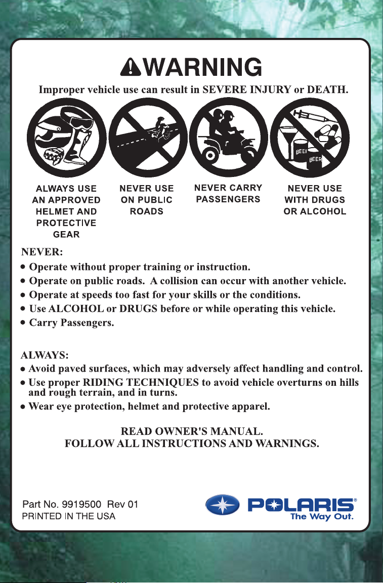
WARNING
The engine exhaust from this
product contains chemicals known
to cause cancer, birth defects or
other reproductive harm.
A card containing important ATV safety information should be attached
to the owner’s manual on the next page. If you cannot locate this card,
or if it has been removed, please call 1-800-342-3764 for assistance.
Page 3
Page 4

Page 5

Copyright 2004 Polaris Sales Inc. All information contained within this publication is
based on the latest product information at the time of publication. Due to constant
improvements in the design and quality of production components, some minor
discrepancies may result between the actual vehicle and the information presented in this
publication. Depictions and/or procedures in this publication are intended for reference
use only. No liability can be accepted for omissions or inaccuracies. Any reprinting or
reuse of the depictions and/or procedures contained within, whether whole or in part, is
expressly prohibited.
Printed in U.S.A.
2005 Sportsman 6x6 Owner’s Manual P/N 9919500
2
Page 6

WELCOME
Thank you for purchasing a Polaris vehicle, and welcome to our
world-wide family of Polaris owners. We proudly produce an exciting
line of utility and recreational products. Visit our Web site at
www.polarisindustries.com.
Polaris Recreational Vehicles
S Snowmobiles
S All-terrain vehicles (ATVs)
S RANGER utility vehicles
S Watercraft
S Victory motorcycles
We believe Polaris sets a standard of excellence for all utility and
recreational vehicles manufactured in the world today. Many years of
experience have gone into the engineering, design, and development of
your Polaris vehicle, m aking it the finest vehicle we’ve ever produced.
For safe and enjoyable operation of your vehicle, be sure to follow the
instructions and recommendations in this owner’s manual. Your
manual contains instructions for minor maintenance, but information
about major repairs is outlined in the Polaris Service Manual and
should be performed only by a Factory Certified Master S ervice Dealer
(MSD) Technician.
Your Polaris dealer knows your vehicle best and is interested in your
total satisfaction. Be sure to return to your dealership for all of your
service needs during, and after, the warranty period.
We also take great pride i n our Parts, Apparel and Accessories (PAA)
products, available through our online store at www.purepolaris.com.
Have your accessories and clothing delivered right to your door!
POLARIS and POLARIS THE WAY OUT are registered trademarks of
Polaris Industries Inc.
3
Page 7

4
Page 8

TABLE OF CONTENTS
WELCOME 3.................................
VEHICLE IDENTIFICATION NUMBERS 7........
SAFETY 8...................................
FEATURES A ND CONTROLS 33...............
OPERATION 49..............................
EMISSION CONTROL SYSTEMS 68............
MAINTENANCE AND LUBRICATION 69.........
POLARIS PRODUCTS 113.....................
SPECIFICATIONS 114........................
TROUBLESHOOTING 116.....................
WARRANTY 120..............................
INDEX 129...................................
5
Page 9

6
Page 10
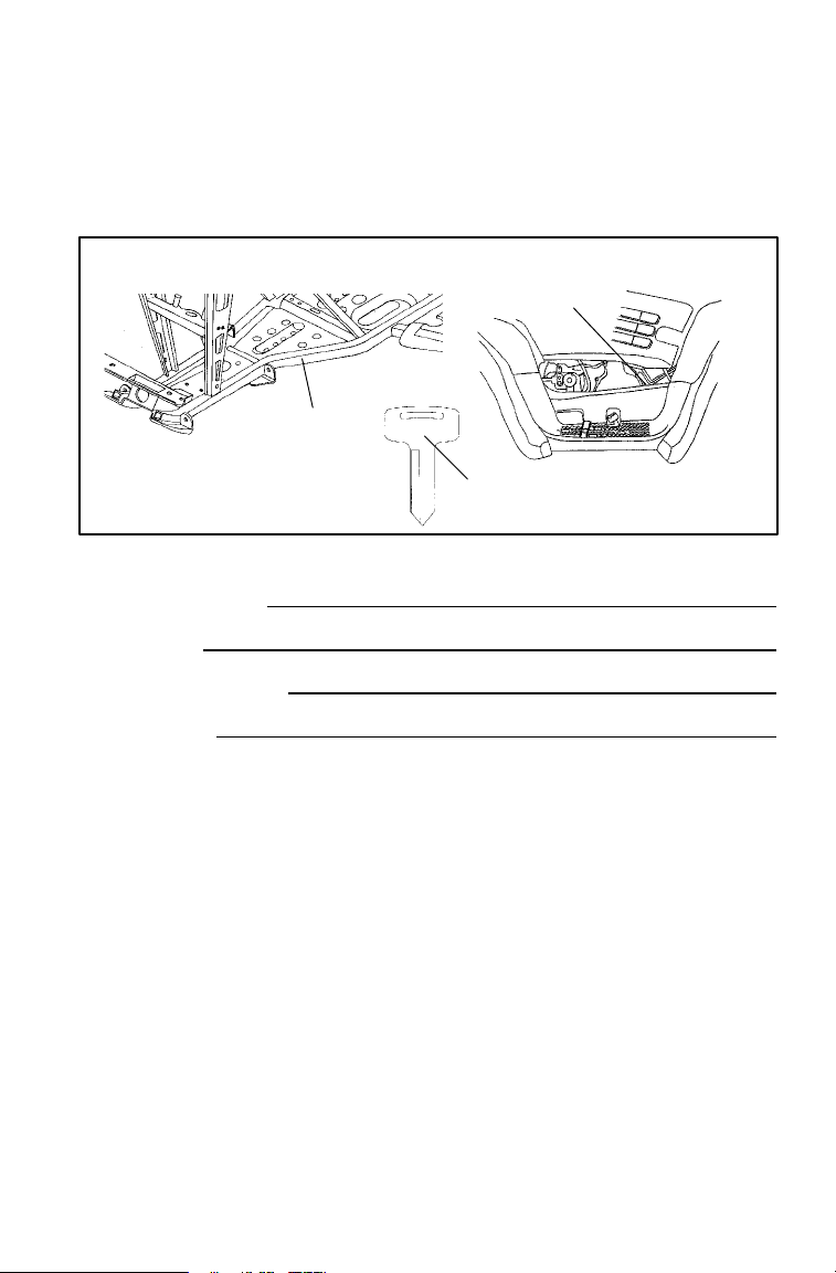
VEHICLE IDENTIFICATION NUMBERS
Record your ATV’s identification numbers and key number in the
spaces provided. Remove the spare key and store it in a safe place.
Your key can be duplicated only by mating a Polaris key blank with
one of your existing keys, so if both keys are lost, t he ignition switch
must be replaced.
2
Vehicle Model Number:
Frame VIN (1):
Engine Serial Number (2):
Key Number (3):
1
31XX
3
7
Page 11
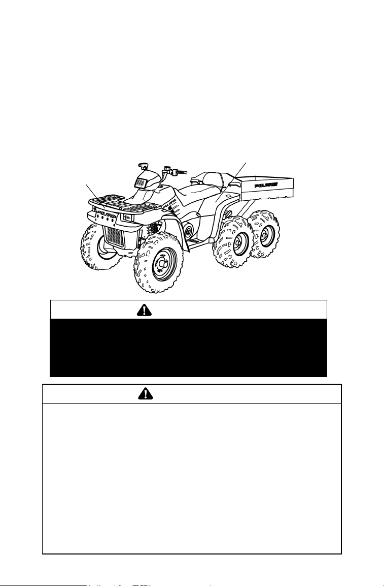
SAFETY
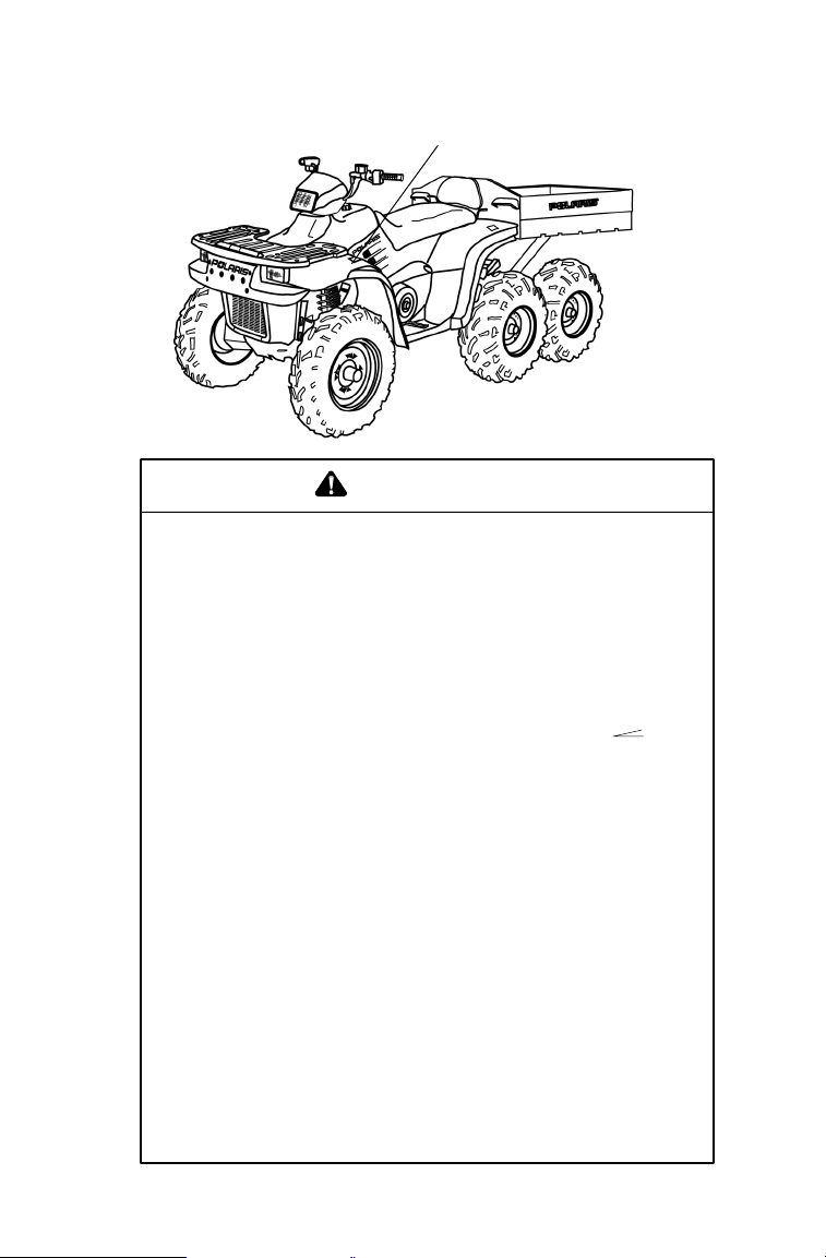
Safety Decals and Locations
Warning decals have been placed on the ATV for your protection. Read
and follow the instructions of the decals on the ATV carefully. If any
of the decals depicted in this manual differ from the decals on your
ATV, always read and follow the instructions of the decals on the ATV.
If any decal becomes illegible or comes off, contact your Polaris dealer
to purchase a replacement. Replacement safety decals are provided by
Polaris at no charge. The part number is printed on the decal.
2
1
WARNING
S DO NOT TOW FROM RACK OR BUMPER.
1
Vehicle damage or tipover may result causing severe
injury or death. Tow only from tow hooks or hitch.
S Maximum Front Rack Load 75 lbs.
WARNING
IMPROPER TIRE PRESSURE OR OVERLOADING can cause
loss of control resulting in SEVERE INJURY OR DEATH.
TIRE PRESSURE IN PSI (Kpa): FRONT 5 (34,5) CENTER 5 (34,5)
MAXIMUM WEIGHT CAPACITY (Gross Vehicle Weight
2
8
INCLUDING MACHINE, DRIVER AND CARGO IS 1965 LBS. (893 kg)
Reduce speed and allow greater distance for braking when carrying cargo.
Overloading or carrying tall, off-center, or unsecured loads will increase
your risk of losing control. Loads should be centered, carried as low as
possible in bed, and firmly secured to the rack.
For stability on rough or hilly terrain, reduce speed and cargo. Do not block
headlight. Be careful if load extends over the side of the rack or box.
Read Owner’s Manual for more detailed loading information.
7172592
REAR 5 (34,5)
7172591
Page 12
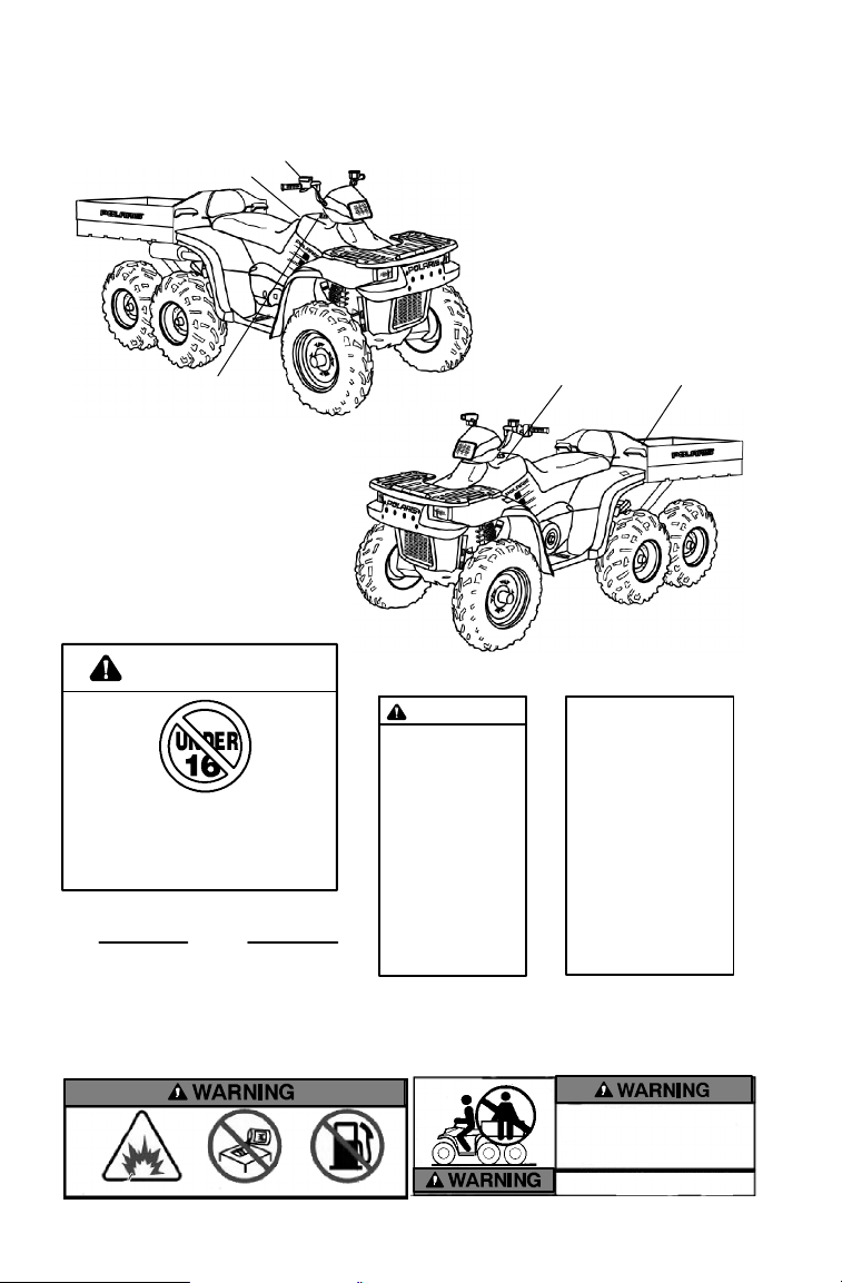
Safety Decals and Locations
3
WARNING
Improper vehicle use can result in SEVERE INJURY or DEATH.
3
NEVER:
DOperate on public roads. A collision can occur with another vehicle.
DCarry passengers. Passengers affect balance and steering and in-
crease risk of losing control.
DUSE ALCOHOL or DRUGS before or while operating this vehicle.
DOperate at speeds too fast for your skills or the conditions.
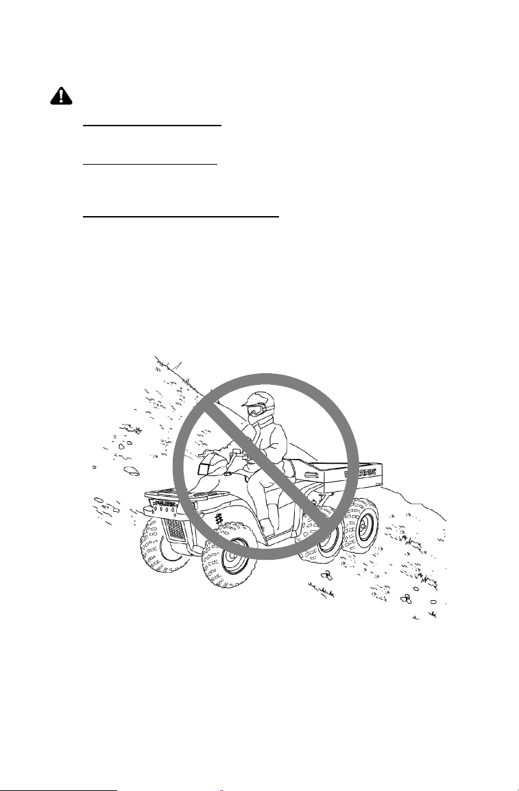
DOperate this vehicle on HILLS steeper than 15 degrees
To prevent flipover on hilly terrain, use throttle and brakes gradually.
ALWAYS:
DUse an approved HELMET AND PROTECTIVE GEAR.
DAvoid paved surfaces. Pavement may seriously affect handling and
control.
DUse proper RIDING TECHNIQUES to avoid vehicle overturns on
hills and rough terrain and in turns.
DUse OVERRIDE for reverse speed limiter with caution. To prevent
loss of control, never activate override button with open throttle.
DREVERSE operation can be dangerous, even at low speeds. Steer-
ing becomes difficult. To prevent flipover, avoid sharp turns.
PARKING BRAKE may relax when used for more than 5 minutes.
When parking on grades, leave shift in forward.
LOCATE AND READ OWNER’S MANUAL. FOLLOW ALL
INSTRUCTIONS AND WARNINGS. IF OWNER’S MANUAL IS
MISSING, CONTACT A POLARIS DEALER FOR A
REPLACEMENT.
SAFETY
15°.
7172589
9
Page 13
SAFETY
Safety Decals and Locations
5
4
8
4
WARNING
Operating this vehicle if you are under the
age of 16 increases your chance of severe
injury or death.
NEVER opera te this ve hicle if you are under
age 16.
This vehicle is equipped with a
Polaris Electronic Throttle Control
5
(ETC) to reduce the risk of a stuck or
“frozen” throttle. Please refer to your
owner’s manual for details.
ETC
7172588
7
6
78
WARNING
Pushing reverse
override button
may cause
sudden increases
in power and
traction if too
much throttle is
applied. Loss of
control or forward
flipover may
result, especially
in AWD. See
Owner’s Manual.
7172564
ALL WHEEL
DRIVE
SWITCH
Do not push switc h to
engage AWD if the rear
wheels are spinning.
This may cause severe
drive shaft and clutch
damage.
See your owner’s
manual.
7079780
6
Remove flammable containers from before refueling.
10
DPassengers can be thrown off.
This can cause serious injury
or death.
DNever carry passengers.
Maximum Box Load 800 lbs.
Page 14
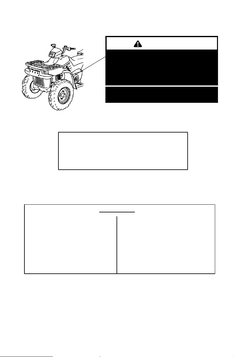
Safety Decals and Locations
S Moving parts hazard under belt-clutch guard. To
prevent serious injury, do not operate vehicle
with guard removed.
S Do not modify engine or clutch. Doing so can
cause part failure, possible imbalance, and
excessive engine RPM, which can result in serious
injury or death.
SAFETY
WARNING
TRAILER MAX WEIGHT:
1500 LBS. (682 KG) ON LEVEL GROUND
850 LBS. (386 KG) UP TO 15° GRADE
HITCH MAX. VERTICAL WEIGHT: 150 LBS. (68KG)
(on hitch)
ATTENTION
S Operation of this vehicle without the
filter element will severely damage
the engine.
S Clean air filter often, more frequent
cleaning required in dusty conditions.
S Operation of this vehicle without en-
gine breather filter(s) can cause engine damage. Consult owner’s
manual for details.
(under seat)
NO STEP
7170509
S Specific carburetor jetting and adjust-
ments are required depending on temperature and altitude. See your owner’s
manual.
Factory setting:
40_ to 80_ F . at 0-3000 feet
(5_ to 27_ C. at 0-900 meters).
7079902
7172563
11
Page 15
SAFETY
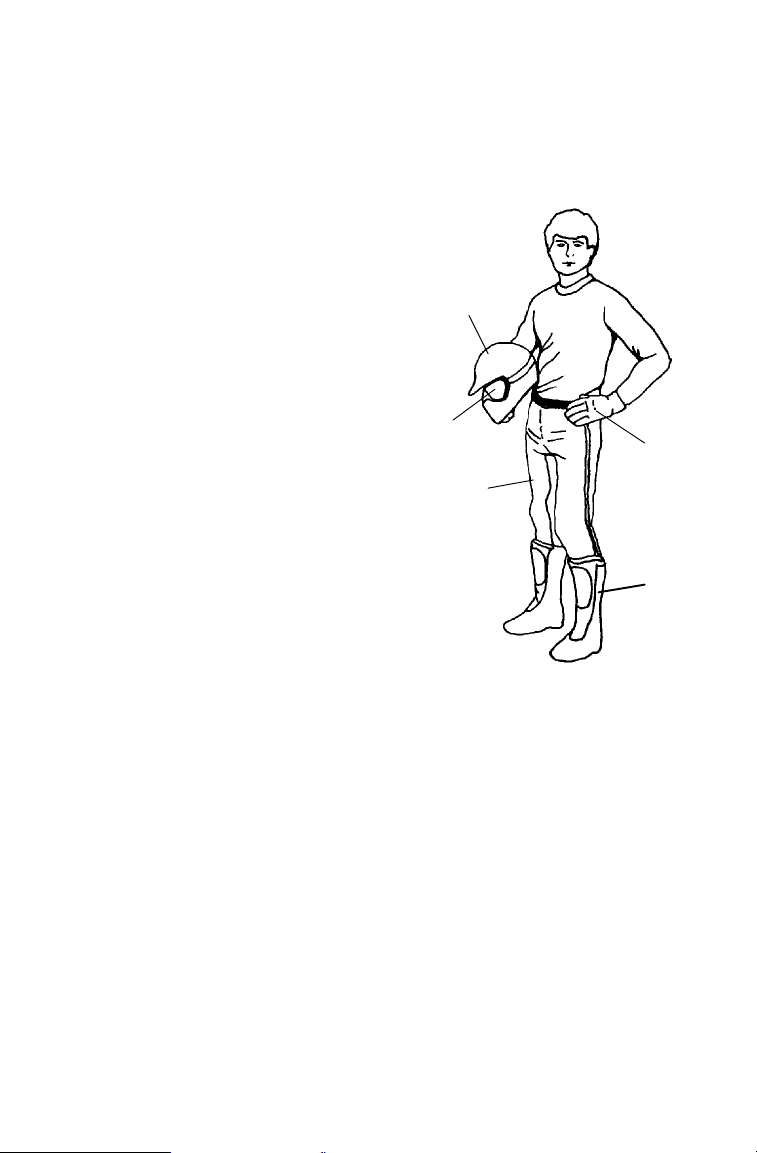
Safe Riding Gear
Always wear clothing suited to the type of riding. ATV riding requires
special protective clothing for comfort and to reduce the chance of
injury.
1. Helmet
Your helmet is the most important piece
of protective gear for safe riding. A
helmet can prevent a severe head injury.
Select an approved helmet that meets
or exceeds your state’ s safety standards
and bears either the Department of
Transportation (DOT) label, the
American National Standards
Institute label (ANSI z90.1), or the
Snell Memorial Foundation label.
2. Eye Protection
Do not depend on sunglasses for
proper eye protection. A pair of
goggles or a helmet face shield offer
the best protection for your eyes. They
should be kept clean and be of
shatterproof design (bearing t he
markings Z2.1 or VESC 8).
1
2
3
5
4
3. Gloves
Off-road style gloves with knuckle pads are the best for comfort and
protection.
4. Boots
The best footwear is a pair of strong over-the-calf boots with heels, like
moto-cross boots.
5. Clothing
Always wear long sleeves and long pants to protect arms and legs.
Riding pants with kneepads and a jersey with shoulder pads provide
the best protection.
12
Page 16

SAFETY
Operator Safety
WARNING
Failure to follow the warnings contained in this manual can result
in serious injury or death.
A Polaris ATV is not a toy and can be hazardous to operate. This
vehicle handles differently than other vehicles, such as
motorcycles and cars. A collision or rollover can occur quickly,
even during routine maneuvers like turning, or driving on hills or
over obstacles, if you fail to take proper precautions.
Read and understand your owner’s manual and all warnings
before operating a Polaris ATV.
Age Restrictions
This vehicle is an ADULT VEHICLE ONLY. Operation is prohibited
for anyone under 16 years of age.
Know Your Vehicle
As the operator of the vehicle, you are responsible for your personal
safety, the safety of others, and the protection of our environment.
Read and understand your owner’s manual, which includes valuable
information about all aspects of your vehicle, including safe operating
procedures.
Safety Training
When you purchased your new ATV, your dealer offered a hands-on
safety training course that covers all aspects of vehicle safety. You
were also provided with printed materials that explain safe operating
procedures. You should review this information on a regular basis.
If you purchased a used Polaris ATV from a party other than a Polaris
dealer, you can request this free safety training from any authorized
Polaris dealer.
A Polaris ATV is an off-road vehicle. Familiarize yourself with all
laws and regulations concerning the operation of the ATV in your area.
We strongly advise you to strictly follow the recommended
maintenance program outlined in your owner ’s manual. This
preventive maintenance program is designed to ensure that all critical
components on your vehicle are t horoughly inspected at specific
intervals.
13
Page 17

SAFETY
Operator Safety
The following signal words and symbols appear throughout this
manual and on your vehicle. Your safety is involved when these words
and symbols are used. Become familiar with their meanings before
reading the manual.
The safety alert symbol, on your vehicle or in this manual, alerts
you to the potential for personal injury.
WARNING
The safety alert warning indicates a potential hazard that may
result in serious injury or death.
CAUTION
The safety alert caution indicates a potential hazard that may
result in minor personal injury or damage to the vehicle.
CAUTION
A caution indicates a situation that may result in damage to the
vehicle.
NOTE:
A note will alert you to important information or instructions.
14
Page 18

SAFETY
Operator Safety
WARNING
Serious injury or death can result if you do not follow these
instructions and procedures, which are outlined in further detail
within your owner’s manual.
S Read this manual and all labels carefully, and follow the operating
procedures described.
S Never operate the S portsman 6x6 without proper instruction. Tak e a
training course. Beginners should receive training from a certified
instructor. Contact an authorized Polaris dealer or call Polaris at
1-800-342-3764 to find out about the training courses nearest you.
S Never allow anyone under 16 years of age to operate this vehicle.
S Never permit a guest to operate the vehicle unless the guest has read
this manual and all product labels and has completed a certified safety training course.
S Always avoid operating this vehicle on paved surfaces, including
sidewalks, driveways, parking lots, and streets.
S Never operate this vehicle on a public street, road or highway, in-
cluding a dirt or gravel road.
S Never operate this vehicle without wearing an approved helmet that
fits properly. Always wear eye protection (goggles or face shield),
gloves, boots, a long-sleeved shirt or jacket, and long pants.
S Never consume alcohol or drugs before or while operating this ve-
hicle.
S Never operate at excessive speeds. Travel at speeds appropriate for
the terrain, visibility and operating conditions, and your experience.
S Never attempt wheelies, jumps or other stunts.
S Always inspect your vehicle before each use to make sure it’s in safe
operating condition. Always follow the inspection and maintenance
procedures and schedules outlined in your owner’s manual.
S Always keep both hands on the handlebars and both feet on the foot-
rests of the vehicle during operation.
S Always travel slowly and use extra caution when operating on unfa-
miliar terrain. Be alert to changing terrain conditions.
S Never operate on excessively rough, slippery, or loose terrain.
S Always follow recommended turning procedures as described in this
manual. Practice turning at low speeds before attempting to turn at
faster speeds. Do not turn at excessive speeds.
15
Page 19

SAFETY
Operator Safety
S Always have the vehicle inspected by an authorized Polaris dealer if
it’s been involved in an accident.
S Never operate on hills too steep for the vehicle or for your abilities.
Practice on smaller hills before attempting larger hills.
S Always follow proper procedures for climbing hills. Check the ter-
rain carefully before ascending a hill. Never climb hills with excessively slippery or loose surfaces. Shift your weight forward. Never
open the throttle suddenly or make sudden gear changes. Never go
over the top of a hill at high speed.
S Always follow proper procedures for going downhill and for braking
on hills. Check the terrain carefully before you start down a hill.
Shift your weight backward. Never go down a hill at high speed.
Avoid going down a hill at an angle, which would cause the vehicle
to lean sharply t o one side. Travel straight down the hill when possible.
S Always follow proper procedures for crossing the side of a hill.
Avoid hills with excessively slippery or loose surfaces. Shift your
weight to the uphill side of the vehicle. Never attempt to turn the
vehicle around on any hill until you’ve mastered (on level ground)
the turning technique outlined in this manual. Avoid crossing the
side of a steep hill when possible.
S Always use proper procedures if the vehicle stalls or rolls backwards
while climbing a hill. To avoid stalling, maintain a steady speed
when climbing a hill. Always dismount on the uphill side, or to either side if the vehicle is pointed straight uphill. Turn the vehicle
around and remount following the procedure described in this manual.
S Always check for obstacles before operating in a new area. Never
attempt to operate over large obstacles, such as rocks or fallen t rees.
S Always be alert to the potential for skidding or sliding. On slippery
surfaces (like ice), travel slowly and use extra caution to reduce the
chance of skidding or sliding out of control.
S Avoid operating the vehicle through deep or fast-flowing water. If
it’s unavoidable, travel slowly, balance your weight carefully, avoid
sudden movements, and maintain a slow and steady forward motion.
Do not make sudden t urns or stops, and do not make sudden throttle
changes.
16
Page 20

SAFETY
Operator Safety
S Wet brakes may have reduced stopping ability. Test your brakes af-
ter leaving water. If necessary, apply them lightly several times to
allow friction t o dry out the pads.
S Always check for obstacles or people behind the vehicle before oper-
ating in reverse. When it’s safe to proceed in reverse, move slowly
and avoid turning at sharp angles.
S Always use the size and type of tires specified for your vehicle, and
always maintain proper tire pressure.
S Never modify this vehicle t hrough improper installation or use of
accessories.
S Never exceed the stated load capacity for your vehicle. Cargo must
be properly distributed and securely attached. Reduce speed and
follow the instructions in this manual for hauling cargo or towing.
Allow a greater distance for braking.
S Always remove the ignition key when the vehicle is not in use to
prevent unauthorized use or accidental starting.
FOR MORE INFORMATION ABOUT ATV SAFETY , call the Consumer Product Safety Commission at 1-800-638-2772, or call
Polaris at 1-800-342-3764.
Equipment Modifications
We are concerned for the safety of our customers and for the general
public. Therefore, we strongly recommend that consumers do not
install on a Polaris Sportsman 6x6 any equipment that may increase the
speed or power of the vehicle, or make any other modifications to the
vehicle for these purposes. Any modifications to the original
equipment of the vehicle create a substantial safety hazard and increase
the risk of bodily injury.
The warranty on your Polaris Sportsman 6x6 is terminated if any
equipment has been added to the vehicle, or if any modifications have
been made to the vehicle, that increase its speed or power.
NOTE: The addition of certain accessories, including (but not limited
to) mowers, blades, tires, sprayers, or large racks, may
change the handling characteristics of the vehicle. Use only
Polaris-approved accessories, and familiarize yourself with
their function and effect on the vehicle.
17
Page 21

SAFETY
Operator Safety
WARNING
POTENTIAL HAZARD
Operating this vehicle without proper instruction.
WHAT CAN
The risk of an accident is greatly increased if the operator does
not know how to operate the vehicle properly in different
situations and on different types of terrain.
HOW TO AVOID THE
Beginning and inexperienced operators should complete the
certified training course offered by Polaris. Operators should
regularly practice the skills learned in the course and the
operating techniques described in the owner’s manual.
For more information about the training course, contact an
authorized Polaris dealer or call Polaris at 1-800-342-3764.
HAPPEN
HAZARD
WARNING
POTENTIAL HAZARD
Failure to follow the age recommendations for this vehicle.
WHAT CAN
Severe injury and/or death could occur if a person under the age
of 16 operates the Sportsman 6x6.
Even though a child may be within the recommended age group
for operating some vehicles, he/she may not have the skills,
abilities, or judgment needed to operate the Sportsman 6x6 safely
and could be susceptible to accident or injury.
HOW TO AVOID THE
No one under the age of 16 should operate a Polaris Sportsman
6x6.
HAPPEN
HAZARD
18
Page 22
Operator Safety
WARNING
POTENTIAL HAZARD
Carrying a passenger on a Sportsman 6x6.
WHAT CAN
Carrying a passenger greatly reduces the operator’s ability to
balance and control the vehicle, which could cause an accident
and injury to the operator and/or passenger.
HOW TO AVOID THE
Never carry a passenger. The purpose of the long seat is to
allow the operator to shift position as needed during operation. It
is not intended for carrying passengers.
HAPPEN
HAZARD
WARNING
POTENTIAL HAZARD
Operating a Sportsman 6x6 on paved surfaces, including
sidewalks, paths, parking lots, and driveways.
WHAT CAN
Sportsman 6x6 tires are designed for off-road use. Operating on
paved surfaces may seriously affect the handling and control of
the vehicle and could result in loss of control, accident, and/or
injury.
HOW TO AVOID THE
Avoid operating the Sportsman 6x6 on pavement. If it’s
unavoidable, travel slowly and avoid sudden turns or stops.
HAPPEN
HAZARD
SAFETY
WARNING
Safe operation of this rider active vehicle requires good
judgement and physical skills. Persons with cognitive or physical
disabilities who operate this vehicle have an increased risk of
overturns and loss of control, which could result in serious injury
or death.
19
Page 23

SAFETY
Operator Safety
WARNING
POTENTIAL HAZARD
Operating this vehicle on public streets, roads or highways.
WHAT CAN
The vehicle could collide with another vehicle.
HOW TO AVOID THE
Never operate the Sportsman 6x6 on any public street, road or
highway, including dirt and gravel roads.
HAPPEN
HAZARD
WARNING
POTENTIAL HAZARD
Operating this vehicle without wearing an approved helmet, eye
protection and protective clothing.
WHAT CAN
Operating a Sportsman 6x6 without an approved helmet
increases the risk of a severe head injury or death in the event of
an accident.
Operating without eye protection could result in an accident and
could increase the chance of a severe injury in the event of an
accident.
HOW TO AVOID THE
Always wear an approved helmet that fits properly.
Always wear eye protection (goggles or face shield), gloves,
boots, long-sleeved shirt or jacket, and long pants.
HAPPEN
HAZARD
20
Page 24

SAFETY
Operator Safety
WARNING
POTENTIAL HAZARD
Stalling or rolling backwards while climbing a hill.
WHAT CAN
Stalling or rolling while climbing a hill could result in vehicle
overturn.
HOW TO AVOID THE
Maintain steady speed when climbing a hill.
Ifyouloseallforward
Keep your body weight toward the front of the vehicle (uphill).
Apply the brakes. After the vehicle has completely stopped, lock
the parking brake.
If you begin rolling
Keep your body weight toward the front of the vehicle (uphill).
Do not apply engine power.
Do not apply the rear brakes.
Gradually apply the service brake. When fully stopped, apply the
auxiliary brake as well, and then lock the parking brake.
Dismount on the uphill side, or to either side if the vehicle is
pointed straight uphill.
Turn the vehicle around and remount, following the procedure
described in the owner’s manual. See page 62. In the event of
an accident, have an authorized Polaris dealer inspect the entire
vehicle for possible damage, including (but not limited to) brakes,
throttle and steering.
HAPPEN
HAZARD
speed:
backwards:
21
Page 25
SAFETY
Operator Safety
WARNING
POTENTIAL HAZARD
Operating the Sportsman 6x6 at excessive speeds.
WHAT CAN
Excessive speed increases the operator’s chance of losing
control of the vehicle, which can result in an accident.
HOW TO AVOID THE
Always operate the vehicle at a speed that’s proper for the
terrain, visibility and operating conditions, and your experience.
HAPPEN
HAZARD
WARNING
POTENTIAL HAZARD
Improperly operating in reverse.
WHAT CAN
The Sportsman 6x6 could collide with an obstacle or person,
resulting in severe injury.
HOW TO AVOID THE
Before shifting into reverse gear, always check for obstacles or
people behind the vehicle. When it’s safe to proceed, back
slowly.
HAPPEN
HAZARD
WARNING
POTENTIAL HAZARD
Failure to inspect the vehicle before operating.
Failure to properly maintain the vehicle.
WHAT CAN
Poor maintenance increases the possibility of an accident or
equipment damage.
HOW TO AVOID THE
Always inspect your vehicle before each use to make sure it’s in
safe operating condition.
Always follow the inspection and maintenance procedures and
schedules described in the owner’s manual.
22
HAPPEN
HAZARD
Page 26
Operator Safety
WARNING
POTENTIAL HAZARD
Removing hands from the handlebars or feet from the footrests
during operation.
WHAT CAN
Removing even one hand or foot can reduce ability to control the
vehicle or could cause loss of balance and ejection from the
vehicle.
If the operator’s foot is not firmly planted on the footrest, it could
come into contact with the rear wheels and lead to accident or
injury.
HOW TO AVOID THE
Always keep both hands on the handlebars and both feet on the
footrests of the vehicle during operation.
HAPPEN
HAZARD
WARNING
POTENTIAL HAZARD
Skidding or sliding.
WHAT CAN
Skidding or sliding can cause loss of control.
If the tires regain traction unexpectedly, the vehicle could
overturn.
HOW TO AVOID THE
On slippery surfaces such as ice, travel slowly and use extra
caution to reduce the chance of skidding or sliding out of control.
HAPPEN
HAZARD
SAFETY
WARNING
POTENTIAL HAZARD
Failure to use extra caution when operating the vehicle on
unfamiliar terrain.
WHAT CAN
Unfamiliar terrain may contain hidden rocks, bumps, or holes that
could cause loss of control or overturn.
HOW TO AVOID THE
Travel slowly and use extra caution when operating on unfamiliar
terrain. Always be alert to changing terrain conditions.
HAPPEN
HAZARD
23
Page 27

SAFETY
Operator Safety
WARNING
POTENTIAL HAZARD
Failure to use extra caution when operating on excessively rough,
slippery or loose terrain.
WHAT CAN
Operating on excessively rough, slippery or loose terrain could
cause loss of traction or loss of control, which could result in an
accident or overturn.
HOW TO AVOID THE
Do not operate on excessively rough, slippery or loose terrain
until you’ve learned and practiced the skills necessary to control
thevehicleonsuchterrain.
Always use extra caution on rough, slippery or loose terrain.
HAPPEN
HAZARD
WARNING
POTENTIAL HAZARD
Turning improperly.
WHAT CAN
Improper turns could cause loss of control and lead to a collision
or overturn.
HOW TO AVOID THE
Always follow proper procedures for turning as described in the
owner’s manual.
Practice turning at slow speeds before attempting to turn at faster
speeds.
Never turn at excessive speed.
HAPPEN
HAZARD
24
Page 28

SAFETY
Operator Safety
WARNING
POTENTIAL HAZARD
Operating on excessively steep hills.
WHAT CAN
The vehicle may overturn and cause serious injury or death.
HOW TO AVOID THE
Never operate on hills too steep for the vehicle or for your
abilities. Never operate the Sportsman 6x6 on hills steeper than
15_.
Practice on small hills before attempting larger hills.
HAPPEN
HAZARD
WARNING
POTENTIAL HAZARD
Climbing hills improperly.
WHAT CAN
Improper hill climbing could cause loss of control or overturn.
HOW TO AVOID THE
Always follow proper procedures for climbing hills as described in
the owner’s manual.
Always check the terrain carefully before ascending any hill.
Never climb hills with excessively slippery or loose surfaces.
Shift your weight forward.
Never open the throttle suddenly while traveling uphill. The
vehicle could flip over backwards.
Never go over the top of any hill at high speed. An obstacle, a
sharp drop, or another vehicle or person could be on the other
side of the hill.
HAPPEN
HAZARD
25
Page 29
SAFETY
Operator Safety
WARNING
POTENTIAL HAZARD
Traveling downhill improperly.
WHAT CAN
Improperly descending a hill could cause loss of control or
overturn.
HOW TO AVOID THE
Always follow proper procedures for traveling down hills as
described in the owner’s manual.
Always check the terrain carefully before descending a hill.
Shift your weight backward.
Never travel down a hill at high speed.
Avoid traveling down a hill at an angle, which would cause the
vehicle to lean sharply to one side. Travel straight down the hill
when possible.
HAPPEN
HAZARD
26
Page 30
Operator Safety
WARNING
POTENTIAL HAZARD
Improperly crossing or turning on hills.
WHAT CAN
Improperly crossing or turning as hills could cause loss of control
or overturn.
HOW TO AVOID THE
Never attempt to turn the Sportsman 6x6 around on any hill until
you’ve mastered the turning technique (on level ground) as
described in the owner’s manual. See page 62. Use extra
caution when turning on any hill.
Avoid crossing the side of a steep hill. If it’s unavoidable, always
follow proper procedures as described in the owner’s manual.
Avoid hills with excessively slippery or loose surfaces.
Shift your weight to the uphill side of the vehicle.
HAPPEN
HAZARD
SAFETY
27
Page 31

SAFETY
Operator Safety
WARNING
POTENTIAL HAZARD
Operating over obstacles.
WHAT CAN
Operating over obstacles could cause loss of control or overturn.
HOW TO AVOID THE
Before operating in a new area, check for obstacles.
Avoid operating over large obstacles such as rocks and fallen
trees. If it’s unavoidable, use extreme caution.
HAPPEN
HAZARD
WARNING
POTENTIAL HAZARD
Overloading the vehicle or carrying/towing cargo improperly.
WHAT CAN
Overloading and towing can cause changes in vehicle handling,
which could lead to loss of control or an accident.
HOW TO AVOID THE
Never exceed the stated load capacity for this vehicle.
Cargo should be properly distributed and securely attached.
Reduce speed when hauling cargo or pulling a trailer. Allow a
greater distance for braking.
Always follow the instructions in the owner’s manual for carrying
cargo or pulling a trailer. See pages 54-55.
HAPPEN
HAZARD
28
Page 32

SAFETY
Operator Safety
WARNING
POTENTIAL HAZARD
Operating the vehicle through deep or fast-flowing water.
WHAT CAN
Tires may float, causing loss of traction and loss of control, which
could lead to an accident or overturn.
HOW TO AVOID THE
Avoid operating the vehicle through deep or fast-flowing water. If
it’s unavoidable to enter water that exceeds the recommended
maximum depth (see page 64), travel slowly, balance your weight
carefully, avoid sudden movements, and maintain a slow and
steady forward motion. Do not make sudden turns or stops, and
do not make sudden throttle changes.
Wet brakes may have reduced stopping ability. Always test the
brakes after leaving water. If necessary, apply them several
times to let friction dry out the pads.
HAPPEN
HAZARD
WARNING
POTENTIAL HAZARD
Attempting wheelies, jumps and other stunts.
WHAT CAN
Attempting stunts increases the chance of an accident, including
an overturn.
HOW TO AVOID THE
Never attempt wheelies, jumps, or other stunts. Avoid exhibition
driving.
HAPPEN
HAZARD
29
Page 33

SAFETY
Operator Safety
WARNING
POTENTIAL HAZARD
Operating this vehicle with improper tires or with improper or
uneven tire pressure.
WHAT CAN
Use of improper tires, or operation of the vehicle with improper or
uneven tire pressure, could cause loss of control or accident.
HOW TO AVOID THE
Always use the size and type of tires specified in the owner’s
manual Supplement for the vehicle.
Always maintain proper tire pressure.
HAPPEN
HAZARD
WARNING
POTENTIAL HAZARD
Operating the vehicle with improper modifications.
WHAT CAN
Improper installation of accessories or modification of the vehicle
may cause changes in handling, which could lead to an accident.
HOW TO AVOID THE
Never modify the Sportsman 6x6 through improper installation or
use of accessories. All parts and accessories added to the
vehicle must be genuine Polaris Industries Inc. or equivalent
components designed for use on this vehicle and should be
installed and used according to approved instructions. See your
authorized Polaris dealer for more information.
HAPPEN
HAZARD
30
Page 34

SAFETY
Operator Safety
WARNING
POTENTIAL HAZARD
Operating on frozen bodies of water.
WHAT CAN
Severe injury or death can result if the vehicle and/or the operator
fall through the ice.
HOW TO AVOID THE
Never operate the vehicle on a frozen body of water.
HAPPEN
HAZARD
WARNING
POTENTIAL HAZARD
Operating the vehicle after consuming alcohol or drugs.
WHAT CAN
Consumption of alcohol and/or drugs could seriously affect
operator judgment. Reaction time may be slower and operator
balance and perception could be affected.
Consuming alcohol and/or drugs before or while operating the
vehicle could result in an accident and cause severe injury or
death.
HOW TO AVOID THE
Never consume alcohol or drugs before or while operating the
vehicle.
HAPPEN
HAZARD
31
Page 35

SAFETY
Operator Safety
WARNING
Leaving the keys in the ignition can lead to unauthorized use of
the vehicle resulting in serious injury or death. Always remove
the ignition key when the vehicle is not in use.
WARNING
Operating a damaged ATV can result in an accident with serious
injury or death. After any overturn or accident, have a qualified
service dealer inspect the entire machine for possible damage,
including (but not limited to) brakes, throttle and steering
systems.
CAUTION
Exposure to hot components could result in a fire. Always keep
combustible materials away from the exhaust system.
32
Page 36

FEATURES AND CONTROLS
1
3
8
4
7
4
6
2
5
9
1. Service Brake Lever
2. Middle Axle Auxiliary Brake Lever
3. Throttle Lever
4. Box Dump Latch Release
5. Gear Selector
6. Floorboards
7. Backrest
8. Cargo Box
9. Front Rack
33
Page 37

FEATURES AND CONTROLS
Electrical Switches and Indicators
1
2
3
4
5
1. Light Switch/Hi-Lo Beam Control - The lights won’t turn on
unless the main switch is on.
WARNING
Activating the override switch while the throttle is open can cause
loss of control, resulting in severe injury or death. Don’t activate
the override switch while the throttle is open.
2. Override Switch (Reverse Speed Limiter) - This vehicle is
equipped with a reverse speed limiter system. To obtain additional
power while backing, depress the override button. The override switch
also allows activation of All Wheel Drive (AWD) in reverse if the
AWD switch is on.
3. Engine Stop Switch - The engine will not
start or run when the switch is off. Its purpose is
to provide the operator with a quick means of
engine shutdown in case of stuck throttle or other
emergency.
NOTE: Both the main switch and the emergency engine stop switch
shut off all electrical power to the entire vehicle, including
lights. To stop the engine, slide the stop switch either right or
left to the OFF position.
3
4. Main Switch - To start the engine, slide t he stop switch to the
center RUN position and turn the main key switch clockwise past the
ON position. Release the key when the engine starts.
The taillight is on whenever the main switch i s on. Turn the key off to
prevent battery drain.
5. All Wheel Drive (AWD) Switch
34
Page 38

FEATURES AND CONTROLS
Throttle Lever
WARNING
Do not start or operate a vehicle with sticking or improperly
operating throttle controls. Doing so could cause an accident and
lead to severe injury or death.
Always contact your dealer for service repairs if throttle problems
arise.
Failure to check or maintain proper operation of the throttle
system can result in an accident if the throttle lever sticks during
operation.
Always check the lever for free movement and return before
starting the engine. Also check occasionally during operation.
Engine speed and vehicle movement
are controlled by pressing the
throttle lever (1). The throttle lever
is spring loaded, and engine speed
returns to idle when the lever is
released.
This vehicle is equipped with
Polaris Electronic Throttle Control
(ETC), which is designed to reduce
the risk of a frozen or stuck throttle.
If the throttle should stick in an open position, engine RPM will
diminish and power to the rear wheels will cease.
1
WARNING
The Electronic Throttle Control (ETC) stops the engine in the
event of a throttle system malfunction and is provided for your
safety. Do not attempt to modify the ETC system or replace it
with any after market throttle mechanisms.
35
Page 39

FEATURES AND CONTROLS
Brakes
The braking system is controlled by t he two brake levers located on the
handlebars, directly in front of each handgrip.
1
2
Service Brakes
The service brake lever (1) is located on the left handlebar. This lever
controls both front and rear wheel braking action. Use this lever for
normal braking.
Apply the service brakes by squeezing the left brake lever toward the
handlebar. These brakes are hydraulically activated disc brakes.
Always test brake lever travel and check the reservoir fluid level before
riding. The lever should feel firm when squeezed. Any sponginess
would indicate a possible fluid leak or low master cylinder fluid level,
which must be corrected before operating. See your dealer for proper
diagnosis and repairs.
Auxiliary Brakes
The auxiliary brake lever (2) is located on the right handlebar. It
controls braking action for the middle axle (rear brake) only. Use the
auxiliary brakes for additional braking or if the service brake system
fails.
WARNING
Operating the vehicle with a spongy brake lever can result in loss
of brakes, which could cause an accident and lead to serious
injury or death. Never operate the vehicle with a spongy-feeling
brake lever.
36
Page 40

FEATURES AND CONTROLS
Brakes
Master Cylinders
The master cylinders (1) are located
on the left and right handlebars.
Check fluid levels before each use of
the ATV.
View the fluid level through the
indicator window (2) on the top of
the master cylinder. This eye will
appear dark when the fluid level is
full. When fluid is low, the eye will
be clear.
1
2
NOTE: When checking the fluid level, position the ATV on level
ground with the handlebars turned so the top of the reservoir
is level. If the fluid level is low, add DOT 3 brake fluid. DO
NOT OVERFILL. See page 113 for the part numbers of
Polaris products.
WARNING
An over-full master cylinder may cause brake drag or brake
lock-up, which could result in serious injury or death. Maintain
brake fluid at the recommended level. Do not overfill.
WARNING
Never store or use a partial bottle of brake fluid. Brake fluid is
hygroscopic, meaning it rapidly absorbs moisture from the air.
The moisture causes the boiling temperature of the brake fluid to
drop, which can lead to early brake fade and the possibility of
accident or severe injury. After opening a bottle of brake fluid,
always discard any unused portion.
37
Page 41

FEATURES AND CONTROLS
Parking Brake
WARNING
Operating the vehicle while the parking brake is engaged could
result in an accident and serious injury or death. Always check to
be sure the parking brake is disengaged before operating.
Setting the Parking Brake
1. Squeeze and release the left brake
lever two or three times, then
squeeze and hold.
2. Push the park brake lock (1)
forward to engage the brake.
Release the brake lever.
3. To release the parking brake
lock, squeeze and release the brake
lever. It will return to its unlocked position.
Important Safeguards
S The parking brake m ay relax if left on for a long period of time. Al-
ways block the wheels to prevent rolling.
S Always block the wheels on the downhill side of the vehicle if leav-
ing it parked on a hill. Another option i s to park the vehicle in a
sidehill position.
S Never depend on the parking brake alone for more than five minutes
if the vehicle is parked on a hill. Always block the wheels to prevent rolling.
1
38
Page 42

FEATURES AND CONTROLS
Fuel Valve
The fuel valve (1) is located on the left side
panel. It has three positions:
OFF: For vehicle storage and when transporting.
ON: For normal operation.
RES: For reserve supply if main supply is
exhausted.
There’s about a 7 to 10 mile (11.2 to 16 km)
range on the reserve supply. Always refill
the gas tank as soon as possible after using
the main supply. Always return the valve
to the ON position after refueling.
Fuel T ank
The fuel tank filler cap (2) is located directly
below the handlebar. Use either leaded or
unleaded gasoline with a minimum pump
octane number of 87=(R+ M/2).
RES
OFF
ON
2
1
39
Page 43

FEATURES AND CONTROLS
Gear Selector
The transmission gear selector (1)
is located on the right side of
the vehicle directly above and
forward of the engine recoil
starter.
To change gears, stop the
vehicle, and with the engine
idling, move the lever to the
desired gear. Do not attempt to
shift gears with engine speed
above idle or while the vehicle
is moving.
Always place the transmission
in gear with the parking brake locked whenever the vehicle is left
unattended.
Maintaining shift linkage adjustment is important to assure proper
transmission function. See your dealer if you experience any shifting
problems.
1
H
N
R
CAUTION
Shifting gears with the engine speed above idle or while the
vehicle is moving could cause transmission damage.
To change gears, stop the vehicle, and with the engine idling,
move the lever to the desired gear.
L
Belt Life
T o extend belt life, use low forward gear in heavy pulling situations and
when operating at less than seven miles per hour for extended periods of
time.
40
Page 44

FEATURES AND CONTROLS
Recoil Starter
If the battery has been drained or
damaged and cannot start the
engine, use of the recoil starter (1)
will allow vehicle operation until
repairs can be made. The recoil
starter is located on the right side of
the machine.
Polaris 4-cycle engines are
equipped with automatic
decompressors. This makes recoil
starting possible by reducing the amount of compression during
starting. The decompressor senses when the engine is spinning fast
enough to start and restores compression when running.
1. Position the vehicle on a level surface and lock the parking brake
(see page 38).
2. Shift the transmission into neutral.
3. Make sure the engine stop switch is set to RUN and the main key
switch is in the ON position.
NOTE: If the engine is cold, use the choke as outlined on page 52.
4. Grasp the recoil starter rope handle (2) firmly and pull slowly so
you can feel the engine strokes.
2
1
NOTE: Every other stroke will be a “compression stroke” and will
make the rope harder to pull. When a compression stroke is
found, continue pulling the rope just until the engine rolls past
the stroke, then stop pulling immediately.
5. Allow the recoil rope to rewind into the recoil assembly, t hen pull
the rope abruptly and forcefully to start the engine.
6. Repeat steps 4-5 if necessary.
CAUTION
Extending the recoil starter rope until it stops can cause damage
to the recoil assembly. Do not extend the starter rope so far that
it stops.
If the starter rope handle is not seated properly, water may enter
the recoil housing and damage components. Make sure the
handle is fully seated on the recoil housing, especially when
traveling in wet areas.
41
Page 45

FEATURES AND CONTROLS
All Wheel Drive (AWD) System
1
2
The Polaris Sportsman 6x6 is equipped with a unique AWD system
activated by the AWD switch (1) on the right handlebar. When the
switch is off, the vehicle is in rear wheel drive at all times. When the
switch is on, the vehicle is in AWD and the front wheels will
automatically engage any time the rear wheels lose traction. When the
rear wheels regain traction, the front wheels will automatically
disengage.
NOTE: The override switch (2) allows activation of AWD in reverse if
the AWD switch is on.
There is no limit to the length of time the vehicle may remain in AWD.
The AWD switch may be turned on or off while the vehicle is moving.
If the switch is turned off when the front hubs are driving, they will not
release until the rear wheels regain traction.
CAUTION
Switching to AWD while the rear wheels are spinning may cause
severe drive shaft and hub damage. Always switch to AWD while
the rear wheels have traction or are at rest.
42
Page 46

FEATURES AND CONTROLS
All Wheel Drive (AWD) System
Disengaging Wheel Hubs
The hubs normally disengage when operating in reverse. However, one
or both hubs may occasionally remain engaged. If the handlebars pull
to one side, one front hub is engaged. If both hubs are engaged,
steering effort increases but remains balanced from left to right, and
vehicle speed is somewhat restricted.
Disengage the hubs by stopping, shifting to reverse, and backing for a
short distance. Then proceed in forward again.
NOTE: If the hubs remain engaged after following this procedure,
To continue using AWD while operating in reverse, activate both the
override switch and the AWD switch. See page 34.
return the vehicle to your dealer for service.
WARNING
Operating with only one front hub engaged could result in loss of
control, accident, and severe injury or death. When hub
engagement symptoms are present, use the disengaging
procedure before proceeding.
43
Page 47

FEATURES AND CONTROLS
Instrument Cluster
Your ATV is equipped with an instrument cluster that senses vehicle
speed from the right front wheel. The instrument cluster m easures
distance in miles or kilometers as well as hours of operation. It also
includes a reverse speed limiter function that limits the ATV’s speed to
approximately 7-9 mph. Refer to page 34 for additional information.
3
2
1
1. Rider Information Center
2. Speedometer needle - in addition to showing vehicle speed, the
needle flashes when a warning condition exists.
3. Speedometer
CAUTION
To prevent damage, wash the ATV by hand or with a garden hose
using mild soap. Do not use alcohol to clean the instrument
cluster. Immediately clean off any gasoline that splashes on the
instrument cluster. Do not allow insect sprays to come into
contact with the lens.
44
Page 48

FEATURES AND CONTROLS
Instrument Cluster
Rider Information Center
The rider information center is located in the instrument cluster. All
segments will light up for 2.5 seconds at start-up.
NOTE: If the instrument cluster fails to illuminate, a battery
over-voltage may have occurred and the instrument cluster
may have shut off to protect the cluster’s electrical system. If
this occurs, take the ATV to your Polaris dealer for proper
diagnosis.
1. Gear Indicator - As the shift lever is moved, this indicates the
gear the transmission is in:
H = High Range
3
4
6
5
L = Low Range
N = Neutral
R = Reverse
P=Park
2
2. AWD Indicator - This
indicator illuminates
when the electrical
portion of the AWD
system is enabled.
3. Engine Hour Display Indicator
1
8
4. Service Interval/Diagnostic Mode Indicator
5. Low B attery and Over Voltage - This warning usually indicates
that the ATV is being operated at an RPM too low to keep the
battery charged. A low battery warning may also occur under normal
operation if the machine is at idle and high electrical load (lights,
cooling fan, accessories) is applied. Driving at a higher RPM or
connecting a battery charger will usually clear the warning.
6. Odometer/Tachometer/Tripmeter/ Hour Meter
7. Check Engine Warning Indicator - The word HOT will display
alphanumerically when the engine is overheating. Do not continue
to operate the ATV if this warning appears or serious engine
damage could result.
8. Mode Indicator
7
45
Page 49

FEATURES AND CONTROLS
Instrument Cluster
Rider Information Center
The rider information center has 4 standard modes:
Mode 1 - Odometer
Mode 2 - Tripmeter
Mode 3 - Total Service Hours
Mode 4 - Tachometer
The reverse override button on the left handlebar is also the mode
button.
NOTE: If using the mode button to program the rider information
center, or to toggle through the options, the machine cannot
be in reverse.
Mode 1 - Odometer
The odometer records the miles traveled by the ATV.
Mode 2 -Trip Meter
The trip meter records the miles traveled by the ATV on each trip if it’s
reset before each trip. To reset the trip meter, select the trip meter
mode. Press and hold the mode button (override button) until the t otal
changes to 0.
NOTE: In the Rider Information Center, the trip meter display
contains a decimal point, but the odometer displays without a
decimal point.
Mode 3 - Hour Meter
This mode logs the total hours the engine has been in operation.
Mode 4 - Tachometer
The engine RPM is displayed digitally.
NOTE: Small fluctuations in the RPM from day to day may be
normal because of changes in humidity, temperature,
elevation and electrical loads.
46
Page 50

FEATURES AND CONTROLS
Instrument Cluster
Rider Information Center
Diagnostic Mode
The diagnostic mode is for informational purposes only. Please return
your ATV to your dealer for all major repairs.
As long as the gauge is in the diagnostic mode, the wrench icon will
remain lit.
To leave the diagnostic mode, either shift the machine out of neutral or
turn the key switch off and on.
NOTE: Any movement of the tires will also take the machine out of
the diagnostic mode.
To enter the diagnostics mode:
1. Turn the key switch off and wait 10 seconds.
2. Set the park brake and shift the transmission to neutral.
3. Hold the mode/reverse override button and turn the key switch on.
4. Release the switch as soon as the display is activated.
The initial screen display refers to t he software version installed in
your ATV. This information is displayed briefly.
Use the mode/reverse override button to toggle through the diagnostic
screens.
Screen 1: Battery voltage
Screen 2: Tachometer
Screen 3: AWD diagnostic
This gauge indicates whether or not current is flowing through the
AWD coil (only on models with switchable AWD).
Screen 4: Gear circuit diagnostic
This screen displays the resistance value (in ohms) being read at the
gear switch input of the gauge.
47
Page 51

FEATURES AND CONTROLS
Instrument Cluster
Rider Information Center
Diagnostic Mode
Screen 5: Programmable service interval
The purpose of t he programmable service interval is to provide the
consumer and dealer with a convenient reminder for routine
maintenance. When your vehicle leaves the factory, this feature is set at
50 hours. You must enable t he programmable service interval before it
can be used.
Once the service interval mode is set with the hours when service is
due, the hours of actual engine operation are subtracted from the set
hours until 0 is reached. When the counter reaches 0, the wrench icon
will flash quickly for 5 seconds each time the vehicle is started as a
reminder that the periodic maintenance is due.
To set the hours, press and hold the mode/override button until the
wrench icon flashes. When it begins to flash, release the button. The
setting will increase by one hour each time the button i s pressed.
Pressing and holding the button will allow the numbers to escalate
much faster. When the desired time increment is displayed, release the
button and wait for the wrench to stop flashing. When the wrench
stops blinking, your service hours are set.
NOTE: If you scroll past the intended number, hold the button down
until the count turns over to 0. You can then reset the
number.
If the service interval is enabled on your ATV and you wish to turn it
off, toggle to the service interval mode. Press and hold the mode
button for approximately 7 seconds until the word OFF appears in the
Rider Information Center.
Screen 6: Miles/Kilometers toggle
The display in the tripmeter and odometer can be changed to display
either kilometers or miles. The current display mode will be shown as
KM or MP. To change, hold in t he mode button until the letters flash,
then press and release the button once. When the display stops
flashing, the mode has been set.
48
Page 52

OPERATION
Fuel Safety
WARNING
Gasoline is highly flammable and explosive under certain
conditions.
S Always exercise extreme caution whenever handling gasoline.
S Always refuel outdoors or in a well ventilated area with the en-
gine stopped.
S Do not smoke or allow open flames or sparks in or near the
area where refueling is performed or where gasoline is stored.
S Do not overfill the tank. Do not fill the tank neck.
S If gasoline spills on your skin or clothing, immediately wash it off
with soap and water and change clothing.
S Never start the engine or let it run in an enclosed area.
Gasoline powered engine exhaust fumes are poisonous and can
cause loss of consciousness and death in a short time.
S Turn the fuel valve off whenever the vehicle is stored or parked.
WARNING
The engine exhaust from this product contains chemicals known
to cause cancer, birth defects or other reproductive harm.
Operate this vehicle only outdoors or in well-ventilated areas.
49
Page 53

OPERATION
Vehicle Break-in Period
The break-in period for your new Polaris Sportsman 6x6 is defined as
the first ten hours of operation or the time it takes to use the first two
tanks of gasoline. No single action on your part is as important as
following procedures for a proper break-in period. Careful treatment of
a new engine will result in more efficient performance and longer life
for the engine. Perform the following procedures carefully.
CAUTION
Excessive heat build-up during the first three hours of operation
will damage close-fitted engine parts. Do not operate at full
throttle or high speeds for extended periods during the first three
hours of use.
Use of oils other than those recommended by Polaris may cause
serious engine damage. Always use the recommended oil.
Lack of proper lubrication will cause serious engine damage.
Always check the oil level when refueling the vehicle.
1. Fill the fuel tank with either unleaded or leaded fuel that has a
minimum pump octane number of 87= (R+ M)/2.
2. Check the oil reservoir
level indicated on the
dipstick. Add the
recommended oil as
needed to bring the
level within the normal
range (1).
3. Drive slowly at first. Select an open area that will allow room to
familiarize yourself with vehicle operation and handling.
4. Vary the throttle positions.
5. Perform regular checks on fluid levels, controls, and areas outlined
on the daily pre-ride inspection checklist. See page 51.
6. Pull only light loads during the break-in period.
7. Perform a break-in oil change at 20 hours or one month, whichever
comes first.
ADD 8 OZ. NORMAL FULL
1
50
Page 54

OPERATION
Pre-Ride Inspection
WARNING
If a proper inspection is not done before each use, severe injury
or death could result. Always inspect the vehicle before each use
to ensure it’s in proper operating condition.
Pre-Ride Checklist
Item Remarks See
Page
Brake system / lever travel Ensure proper operation 36, 88,
89
Brake fluid Ensure proper level 37
Auxiliary brake Ensure proper operation 36
Front suspension Inspect, lubricate if necessary 74
Rear suspension Inspect, lubricate if necessary 74
Steering Ensure free operation --
Tires Inspect condition and pressure 95, 96
Wheels / fasteners Inspect, ensure fastener tightness 96
Frame nuts, bolts, fasteners Inspect, ensure tightness --
Fuel and oil Ensure proper levels 79
Coolant level (if applicable) Ensure proper level --
Coolant hoses (if applicable) Inspect for leaks --
Throttle Ensure proper operation 35, 89
Indicator lights / switches Ensure operation 34
Engine stop switch Ensure proper operation 34
Drive chain Check condition / slack, lubricate as
needed
Air filter, pre-filter Inspect, clean 84
Air box sediment tube Drain deposits whenever visible --
Headlamp Check operation, apply Polaris dielec-
tric grease when lamp is replaced
Brake light / tail lamp Check operation, apply Polaris dielec-
tric grease when lamp is replaced
Dump box latch Check condition and operation of the
mechanism
Riding gear Wear helmet, goggles, protective
clothing
90, 91
105
108
--
12
51
Page 55

OPERATION
Starting a Cold Engine
WARNING
Carbon monoxide exhaust gas is poisonous and can cause
severe injury or death. Never run an engine in an enclosed area.
CAUTION
Operating the vehicle immediately after starting could cause
engine damage. Allow the engine to warm up for several minutes
before operating the vehicle.
1. Place the transmission in neutral and
lock the parking brake. Make sure the
fuel tank valve is on.
2. Sit on the vehicle and pull the choke
knob (1) out until it stops. The
variable choke is fully on when the
knob is pulled completely out. The
choke is off when the knob is pushed
completely in. The choke can be
adjusted gradually, depending on how
much choke is needed for starting. Be
sure the choke is off during operation,
as excess fuel washing into the engine
oil will increase wear on engine
components.
NOTE: If the knob doesn’t stay where positioned, increase the
tension by rotating the tension adjusting nut (2) clockwise.
3. Turn the engine stop switch to RUN.
1
2
NOTE: Do not press the throttle while starting the engine.
4. Turn the ignition key past the ON position to engage the starter.
Activate the starter for a maximum of five seconds, releasing the
switch when the vehicle starts. If the engine does not start, release
the starter and wait five seconds. Then activate the starter for
another five seconds. Repeat this procedure until the engine starts.
5. If the engine slows or stops, position the choke knob half way in to
allow proper engine warm up.
6. Vary the engine RPM slightly with the throttle to aid in warm-up.
When the engine idles smoothly, push the choke completely in.
52
Page 56

OPERATION
Starting a Warm Engine
Warm engines do not normally require the use of the choke. Excessive
use of the choke can cause the spark plug to become wet fouled.
1. Position the vehicle on a level surface with the transmission in
neutral.
2. Lock the parking brake, turn the fuel tank valve to ON, sit on the
vehicle, and move the engine stop switch to RUN.
3. If the engine has cooled to a point where i t does not readily start,
intermittent use of the choke button (pulled half way out) may be
necessary.
4. If the engine is over-choked when warm, depress the throttle lever
fully while cranking to aid in starting.
5. Release the throttle lever immediately after the engine starts. If the
engine does not start and all conditions are favorable, change the
sparkplugandtryagain.
53
Page 57

OPERATION
Hauling Cargo
Your Sportsman 6x6 has been designed to carry or tow a certain
amount of load. Always read and understand the load distribution
warnings on the warning labels. Never exceed the specified weights.
WARNING
Overloading the vehicle or carrying or towing cargo improperly
can alter vehicle handling and may cause loss of control or brake
instability.
S Never exceed the stated load capacity for this vehicle.
S Do not obstruct the headlight when loading the front rack.
S Cargo should be properly distributed and carried as low and for-
ward in the cargo box as possible.
S Reduce speed and allow a greater distance for braking.
S Use extreme caution when applying brakes with a loaded
vehicle. Avoid terrain or situations that may require backing
downhill.
S Always attach the tow load to the hitch point.
S Do not tow any trailer on a grade steeper than 15
S Vehicle should never exceed 10 mph (16 kph) while towing a
load on a level surface. Vehicle speed should never exceed 5
mph (8 kph) when towing loads in rough terrain, while cornering,
or while ascending or descending a hill.
°.
Maximum Cargo Capacities (Level Ground)
Total Cargo 875 lbs. (397 kg)
Front Rack Cargo 75 lbs. (34 kg)
Cargo Box 800 lbs. (363 kg)
Maximum Towing Capacities
Towed Load (level ground) 1500 lbs. (681 kg)
Towed Load (up to 15° incline)
Vertical Hitch Weight 150 lbs. (68.1 kg)
Towing Grade
54
850 lbs. (386 kg)
15°
Page 58

OPERATION
Hauling Cargo
Dumping Cargo
1. Select a level site to dump the cargo box. Do not attempt to dump
or unload the vehicle while parked on an incline.
2. Set t he parking brake.
3. Dismount the vehicle.
4. Pull the cargo box release lever forward.
5. Lift the front of the cargo box and dump the cargo.
WARNING
If the weight distribution in the box is located toward the rear of
the box when the release lever is pulled forward, the box may
dump on its own, which could cause serious injury. Never
operate the dump lever without checking the position of the load.
This will prevent unexpected dumping of the cargo box. Never
carry passengers in the cargo box.
55
Page 59

OPERATION
Driving Safely
Load Distribution
1
1. Never exceed the maximum capacities for hauling cargo as stated
on the load distribution warning labels and on page 54.
2. Always load the cargo box with the load (1) as far forward as
possible.
3. Always operate the vehicle with extreme caution whenever hauling
or towing loads. Balance, handling and control may be affected.
4. Slow down.
5. The cargo box dump latch must be securely latched before loading
and operating. Unintentional box tilting will result if weight is
placed in the rear of the box and the latch is not secured.
WARNING
Operating with the cargo box in the raised position can cause
serious injury and damage to the vehicle. The cargo box could
close unexpectedly and injure the driver. The rear tires will also
catch the rear of the box, damaging the vehicle and creating
hazardous driving conditions.
Never operate this vehicle with the cargo box in the raised
position.
56
Page 60

OPERATION
Driving Safely
Driving Procedures
1. Sit upright with both feet on the footrests and both hands on the
handlebars.
2. After starting the engine and allowing it to warm up, shift the
transmission into gear.
3. Check your surroundings and determine your path of travel.
4. Release the parking brake.
5. Slowly depress the throttle with your right thumb and begin
driving. Vehicle speed is controlled by the amount of throttle
opening. PVT shifting is automatic.
6. Drive slowly. Practice maneuvering and using the throttle and
brakes on level surfaces.
57
Page 61

OPERATION
Driving Safely
Making Turns
Practice making turns at slow speeds.
The Sportsman 6x6 is equipped with a solid rear axle that drives all
rear wheels equally at all times. This means that the wheel on the
outside of the turn must travel a greater distance than the inside wheel
when turning, and the inside tire must slip traction slightly.
To turn, steer in the direction of the turn, leaning your upper body to
the inside of the turn while supporting your weight on the outer
footrest. This technique alters the balance of traction between the rear
wheels, allowing the turn to be made smoothly. The same learning
technique should be used for turning in reverse.
WARNING
Turning at sharp angles in reverse can result in tipover and
serious injury. Avoid turning at sharp angles while operating in
reverse.
58
Page 62

OPERATION
Driving Safely
Sidehilling
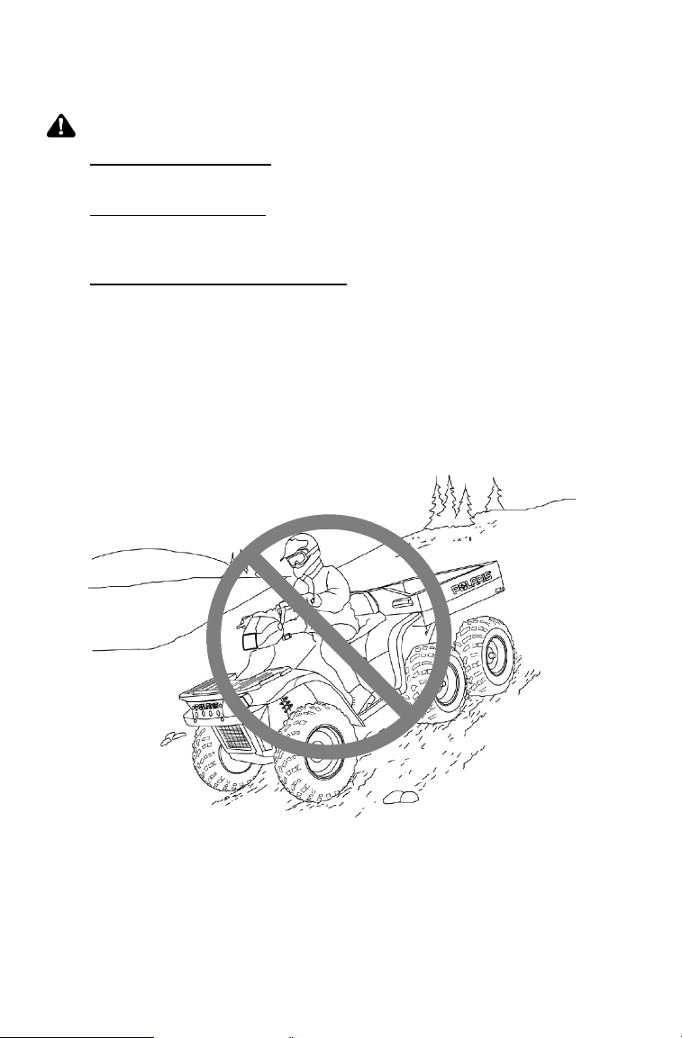
WARNING
Improperly crossing hills or turning on hills can result in loss of
control or vehicle overturn, resulting in severe injury or death.
Avoid crossing the side of a hill.
Sidehilling can be a dangerous type of driving and should be avoided if
at all possible. If you do enter into a situation where sidehilling is
necessary, follow these precautions:
1. Slow down.
2. Lean into the hill, transferring your upper body weight toward the
hill while keeping your feet on the footrests.
3. Steer slightly into the hill to maintain vehicle direction.
NOTE: If the vehicle begins to tip, quickly turn the front wheel
downhill, if possible, or dismount on the uphill side
immediately!
59
Page 63

OPERATION
Driving Safely
Driving Downhill
Whenever descending a hill, follow these precautions:
1. Drive directly downhill.
2. Transfer your weight to the rear of the vehicle.
3. Slow down.
4. Apply the brakes slightly toaidinslowing.
WARNING
Hard use of the braking system while descending a hill could
result in a front-end overturn, causing serious injury or death.
Always operate the brakes slightly when descending a hill.
Excessive speed can cause loss of control and lead to serious
injury or death. Always operate slowly when traveling downhill.
60
Page 64

OPERATION
Driving Safely
Driving Uphill
15° Maximum
Whenever traveling uphill, follow these precautions:
1. Always travel straight uphill.
2. Avoid steep hills.
3. Keep both feet on the footrests.
4. Transfer your weight forward.
5. Proceed at a steady rate of speed and throttle opening.
6. Remain alert and be prepared to take emergency action. This may
include quick dismounting of the vehicle.
WARNING
Braking and handling are greatly affected when operating in hilly
terrain. Improper procedure could cause loss of control or
overturn and result in serious injury or death.
Avoid climbing steep hills (15_ maximum).
Use extreme caution when operating on hills, and follow proper
operating procedures outlined in the owner’s manual.
61
Page 65

OPERATION
Driving Safely
Turning Around on a Hill
WARNING
Improper hill climbing procedures could cause loss of control or
overturn and result in serious injury or death.
Avoid climbing steep hills (15_ maximum).
Use extreme caution when operating on hills, and follow proper
operating procedures outlined in the owner’s manual.
If the vehicle stalls while climbing a hill, never back it down the hill!
One maneuver that can be used when it’s necessary to turn around
while climbing a hill is the K-turn:
1. Stop and lock the parking brake while keeping body weight uphill.
2. Leave the transmission in forward and shut off the engine.
3. Dismount on the left (always uphill) side of the vehicle.
4. Staying uphill of the vehicle, turn the handlebars full l eft.
5. While holding the service brake, release the parking brake lock and
slowly allow the vehicle to roll around to your right until it’s
pointing across the hill or slightly downward.
6. Lock the parking brake and remount the vehicle from the uphill
side, keeping body weight uphill.
7. Restart the engine with the transmission still in forward.
8. Release the parking brake and proceed slowly, controlling speed
with the service brake, until the vehicle is on more level ground.
62
8’
Uphill
Page 66

OPERATION
Driving Safely
Driving on Slippery Surfaces
Whenever operating on slippery surfaces, such as wet trails or loose
gravel, or during freezing weather, follow these precautions:
1. Slow down when entering slippery areas.
2. Maintain a high level of alertness, reading the trail and avoiding
quick, sharp turns, which can cause skids.
NOTE: Correct a skid by turning the handlebars in the direction of
the skid and shifting your body weight forward. Never brake
during a skid.
3. Drive with AWD engaged to assist in controlling the vehicle in
slippery areas.
CAUTION
Severe damage to the drive train may occur if the AWD is
engaged while the wheels are spinning. Activate the AWD switch
only when the rear wheels have traction.
WARNING
Failure to exercise care when operating on slippery surfaces can
result in loss of tire traction and cause loss of control, accident,
and serious injury or death.
Never apply the brakes during a skid.
Do not operate on excessively slippery surfaces.
Always reduce speed and use additional caution when operating
on slippery surfaces.
63
Page 67

OPERATION
Driving Safely
Driving Through Water
1
Your Sportsman 6X6 can operate through water with a maximum
recommended depth equal to the footrests (1). Avoid operating the
ATV through deep or fast-flowing water. If you cannot avoid water
that exceeds the recommended maximum depth, go slowly, balance
your weight carefully, avoid sudden movements, and maintain a slow
and steady forward motion. Do not make sudden turns or stops, and do
not make sudden throttle changes.
Follow t hese procedures when operating through water:
1. Determine water depths and current before crossing.
2. Choose a crossing where both banks have gradual inclines.
3. Proceed slowly, avoiding rocks and obstacles if possible.
4. After crossing, dry the brakes by applying light pressure to the
lever until braking action is normal.
NOTE: After running the vehicle in water, it’s critical to have it
serviced as outlined in the maintenance schedule beginning
on page 70. The following areas need special attention:
engine oil, transmission oil, front and rear gearcases, and all
grease fittings.
CAUTION
Major engine damage can result if the vehicle is not thoroughly
inspected after becoming immersed. If your vehicle becomes
immersed or is operated in water that exceeds the footrest level,
take it to your dealer for service before starting the engine.
64
Page 68

OPERATION
Driving Safely
Driving in Reverse
This vehicle is equipped with a reverse speed limiter. The override
button should be used with caution as rearward vehicle speed is greatly
increased. Do not operate at wide open t hrottle. Open the throttle just
enough to maintain a desired speed.
Follow these precautions
when operating in reverse:
1. Always avoid backing
downhill.
2. Back slowly.
3. When in reverse, apply
the brakes lightly for
stopping.
4. Avoid turning at sharp
angles in reverse.
5. Never open t he throttle
suddenly while backing.
6. Never activate the override button while the throttle is open. Loss
of control may result.
CAUTION
Opening the throttle more than required may cause fuel to build in
the exhaust, resulting in engine popping and/or engine damage.
WARNING
Failure to use caution when operating in reverse can result in
serious injury or death. Before shifting into reverse gear, always
check for obstacles or people behind the vehicle. When it’s safe
to proceed, back slowly.
Do not use the override switch unless additional power is required
for vehicle movement.
Avoid backing on inclines.
Avoid turning at sharp angles in reverse.
65
Page 69

OPERATION
Driving Safely
ParkingOnAnIncline
Avoid parking on an incline if possible. If it’s unavoidable, follow
these precautions:
1. Place the transmission in gear and set the parking brake.
2. Always block the rear wheels on the downhill side. See
illustration.
3. Shut off the fuel supply.
66
Page 70

OPERATION
Driving Safely
Driving Over Obstacles
Keep alert! Look ahead and learn to read the terrain you’re traveling
on. Be constantly alert for hazards such as logs, rocks and low hanging
branches.
WARNING
Severe injury or death can result if your vehicle comes in contact
with a hidden obstacle. Not all obstacles are immediately visible.
Travel with caution in unfamiliar terrain.
67
Page 71

EMISSION CONTROL SYSTEMS
Noise Emission Control System
Do not modify the engine, intake or exhaust components, as doing so
may affect compliance with state and local noise level requirements.
Spark Arrestor
Your Polaris vehicle has a spark arrestor that was tested and approved
in accordance with the USDA Forest Service Standard 5100-1C.
Federal law requires that this spark arrestor be installed and functional
when the vehicle is operated on public lands.
Crankcase Emission Control System
This engine is equipped with a closed crankcase system. Blow-by
gases are forced back to the combustion chamber by the intake system.
The system does not allow the blow-by gases to enter t he atmosphere.
Exhaust Emission Control System
The emissions from the exhaust of this vehicle are controlled by engine
design, including factory-set fuel delivery and ignition. The engine
and related components must be maintained at Polaris specifications to
achieve optimal performance.
Adjustment to engine idle is
the only adjustment Polaris
recommends that the
operator perform. Any other
adjustments should be
performed by an authorized
Polaris dealer.
The emissions label (1) is
located on the recoil cover.
1
Electromagnetic Interference
This spark ignition system complies with Canadian ICES--002.
68
Page 72

MAINTENANCE AND LUBRICATION
Tool Kit
To help you perform routine maintenance, a tool kit is provided in the
storage compartment under the seat. Items included in the kit are:
S Screwdriver
S Open end wrench (8-10 mm)
S Open end wrench (12-14 mm)
S Box end wrench
S Tire pressure gauge
S Spark plug wrench and handle
S Torx wrench (rack removal)
Accessories
Polaris has a wide variety of accessories for your vehicle. Contact your
Polaris dealer for a complete list.
The addition of certain accessories, including (but not limited to)
mowers, blades, tires, sprayers, or large racks may change the handling
characteristics of the vehicle. Be sure any accessories added to the
vehicle have been approved by Polaris. Familiarize yourself with their
function and effect on the vehicle.
69
Page 73

MAINTENANCE AND LUBRICATION
Periodic Maintenance Chart
Careful periodic maintenance will help keep your vehicle in the safest,
most reliable condition. Inspection, adjustment and lubrication of
important components are explained in the periodic m aintenance chart.
Inspect, clean, lubricate, adjust and replace parts as necessary. When
inspection reveals the need for replacement parts, use genuine Polaris
parts available from your Polaris dealer.
NOTE: Service and adjustments are critical. If you’re not familiar
with safe service and adjustment procedures, have a
qualified dealer perform these operations.
Maintenance intervals in the following chart are based upon average
riding conditions and an average vehicle speed of approximately 10
miles per hour. Vehicles subjected to severe use must be inspected and
serviced more frequently.
Severe Use Definition
S Frequent immersion in mud, water or sand
S Racing or race-style high RPM use
S Prolonged low speed, heavy load operation
S Extended idle
S Short trip cold weather operation
Pay special attention to the oil level. A rise in oil level during cold
weather can indicate contaminants collecting in the oil sump or
crankcase. Change oil immediately if the oil level begins to rise.
Monitor the oil level, and if it continues to rise, discontinue use and
determine the cause or see your dealer.
Maintenance Chart Key
" Perform these procedures more frequently for vehicles subjected to
severe use.
E Emission C ontrol System Service (California)
J Have an authorized Polaris dealer perform these services.
WARNING
Improperly performing the procedures marked with a J could
result in component failure and lead to serious injury or death.
Have an authorized Polaris dealer perform these services.
70
Page 74

MAINTENANCE AND LUBRICATION
j
onpage5
1
Periodic Maintenance Chart
Perform all services at whichever maintenance interval is reached first.
Item Maintenance Interval
(whichever comes first)
Hours Calendar Miles
Steering -- Pre-Ride --
J
Front suspension -- Pre-Ride --
"
Rear suspension -- Pre-Ride --
"
Tires -- Pre-Ride --
Brake fluid level -- Pre-Ride --
"
Brake lever travel -- Pre-Ride --
"
Brake systems -- Pre-Ride --
Wheels/fasteners -- Pre-Ride --
Frame fasteners -- Pre-Ride --
Engine oil level -- Pre-Ride --
"
(Km)
Make adjustments as needed. See Pre-Ride Checklist
on page 51.
Remarks
.
E
Air filter, pre-filter -- Daily -- Inspect; clean often
"
E
Air box sediment
"
tube
E
Coolant
(if applicable)
Headlamp/tail
lamp
Air filter,
"
main element
E
Recoil housing -- Weekly -- Drain water as needed,
Brake pad wear 10 H Monthly 60 (100) Inspect periodically
"
J
Battery 20 H Monthly 125 (200) Check terminals; clean; test
Front gearcase oil
"
(if equipped)
Middle gearcase
"
oil (if equipped)
Rear gearcase oil
"
(if equipped)
Transmission oil 25 H Monthly 155 (250) Inspect level; change yearly
"
" Perform these procedures more often for vehicles subjected to severe use.
-- Daily -- Drain deposits when visible
-- Daily -- Check level daily, change
-- Daily -- Check operation; apply
-- Weekly -- Inspect; replace as needed
25 H Monthly 155 (250) Inspect level; change yearly
25 H Monthly 155 (250) Inspect level; change yearly
25 H Monthly 155 (250) Inspect level; change yearly
coolant every 2 years
dielectric grease if replacing
check often if operating in
wet conditions
E Emission Control System Service (California)
J Have an authorized Polaris dealer perform these services.
71
Page 75

MAINTENANCE AND LUBRICATION
Periodic Maintenance Chart
Item Maintenance Interval
(whichever comes first)
Hours Calendar Miles
Engine breather
"
filter (if equipped)
E
Engine oil change
"
(break-in)
E
General
"
lubrication
Shift Linkage 50 H 6M 310 (500) Inspect, lubricate, adjust
Steering 50 H 6M 310 (500) Lubricate
J
Front suspension 50 H 6M 310 (500) Lubricate
"
Rear suspension 50 H 6M 310 (500) Lubricate
"
Carburetor float
bowl
Throttle Cable/
J
ETC Switch
E
Choke cable 50 H 6M 310 (500) Inspect; adjust; lubricate;
J
25 H Monthly 155 (250) Inspect; replace if necessary
25 H 1M 155 (250) Perform a break-in oil
50 H 3M 310 (500) Lubricate all fittings, pivots,
50 H 6M 310 (500) Drain bowl periodically and
50 H 6M 310 (500) Inspect; adjust; lubricate;
E
Carburetor air
E
intake ducts/
flange
Front hub bear-
"
ings (if equipped)
Drive belt 50 H 6M 310 (500) Inspect; adjust; replace as
Cooling system
(if applicable)
Engine oil change 100 H 6M 620 (1000) Perform a break-in oil
"
50 H 6M 310 (500) Inspect ducts for proper
50 H 6M 310 (500) Inspect; clean; replace as
50 H 6M 310 (500) Inspect coolant strength
E
Oil filter change 100 H 6M 620 (1000) Replace with oil change
"
(Km)
change at one month
cables, etc.
prior to storage
replace if necessary
replace if necessary
sealing/air leaks
needed
needed
seasonally; pressure test
system yearly
change at 25 hours/one
month
Remarks
E
Oil tank vent hose 100 H 12 M 620 (1000) Inspect routing, condition
"
E
Valve clearance 100 H 12 M 620 (1000) Inspect; adjust
J
E
" Perform these procedures more often for vehicles subjected to severe use.
E Emission Control System Service (California)
J Have an authorized Polaris dealer perform these services.
72
Page 76

MAINTENANCE AND LUBRICATION
Periodic Maintenance Chart
Item Maintenance Interval
(whichever comes first)
Hours Calendar Miles
Fuel system 100 H 12 M 620 (1000) Check for leaks at tank cap,
J
E
Fuel filter 100 H 12 M 620 (1000) Replace yearly
J
(Km)
lines, fuel valve, filter, pump,
carburetor; replace lines
every two years
Remarks
E
Radiator
"
(if applicable)
Cooling hoses
"
(if applicable)
Engine mounts 100 H 12 M 620 (1000) Inspect
"
Exhaust muffler/
pipe
Spark plug 100 H 12 M 620 (1000) Inspect; replace as needed
J
100 H 12 M 620 (1000) Inspect; clean external
surfaces
100 H 12 M 620 (1000) Inspect for leaks
100 H 12 M 620 (1000) Inspect
E
Ignition Timing 100 H 12 M 620 (1000) Inspect
J
E
Wiring 100 H 12 M 620 (1000) Inspect for wear, routing,
"
Clutches (drive
J
and driven)
Shift selector
J
lubricant
Brake fluid 200 H 24 M 1240 (2000) Change every two years
J
Spark arrestor 300 H 36 M 1860 (3000) Clean out
Idle speed -- Adjust as needed
E
Toe adjustment -- Inspect periodically; adjust
J
Auxiliary brake -- Inspect daily; adjust as
"
J
Headlight aim -- Adjust as needed
100 H 12 M 620 (1000) Inspect; clean; replace worn
200 H 24 M 1240 (2000) Change lubricant every two
security; apply dielectric
grease to connectors
subjected to water, mud, etc.
parts
years
when parts are replaced
needed
" Perform these procedures more often for vehicles subjected to severe use.
E Emission Control System Service (California)
J Have an authorized Polaris dealer perform these services.
73
Page 77

MAINTENANCE AND LUBRICATION
Lubrication Recommendations
Lubricate all components at the intervals outlined in the Periodic
Maintenance Chart beginning on page 70. Items not listed in the chart
should be lubricated at the General Lubrication interval.
Maintenance Chart Key
" More often under severe use, such as wet or dusty conditions
L Use Polaris Premium All Season Grease or grease conforming to
NLGI No. 2
F Use Polaris Premium U-Joint Lube every 500 miles, before long
periods of storage, or after pressure washing or submerging.
Item Lube Rec. Method
Brake Fluid DOT 3 only See page 37.
Drive Chains O-Ring chain lube
Gear Selector Oil Premium 4
Transmission Oil Polaris Premium
Front Prop Shaft Yoke
(Loc. 1)
AWD Hubs (Loc. 2) Premium Demand
Ball Joint (Loc. 3) LGrease Locate zerk on back side of struts and
Rear Axle Bearing
(Loc. 4)
Swing Arm Bushings
(Loc. 5)
Middle Axle Bearings
(Loc. 6)
Center Swing Arm
Housing (Loc. 7)
Rear Strut (Loc. 8) "Grease Locate fitting on rear strut and grease
Tie Rod Ends (Loc. 9) "Grease Grease with grease gun.
or SAE 80/90
Synthetic 0W--40
Synthetic Gearcase
Lube
FGrease Locate fittings and grease
Drive Hub Fluid
LGrease
LGrease
"Grease Locate fitting on eccentric and grease
"Grease Locate fitting on swing arm housing and
Lubricate as often as required (before
each ride in wet conditions).
Maintain oil level at the center of the
shift rail. Do not overfill.
See page 76.
Remove set screw in hubs. Rotate
wheels to 4:00 position (A). If lubricant
is not visible add more. Reinstall set
screw.
grease with grease gun.
Locate fitting on eccentric and grease
with grease gun.
Locate fitting on swing arm and grease
with grease gun.
with grease gun.
grease with grease gun.
with grease gun.
74
Page 78

MAINTENANCE AND LUBRICATION
Lubrication Recommendations
(Loc. 1)
(Loc. 6)
(Loc. 9)
(Loc. 4)
(Loc. 5)
(Loc. 2)
(Loc. 7)
(Loc. 3)
A
(Loc. 8)
75
Page 79

MAINTENANCE AND LUBRICATION
Lubrication Recommendations
Transmission Lubrication
Always check and change the
transmission lubricant at the
intervals outlined in the Periodic
Maintenance Chart beginning on
page 70. Maintain the oil level
at the bottom of the fill hole
threads. Polaris recommends
the use of Premium AGL
Synthetic Gearcase Lubricant.
See page 113 for the part numbers
of Polaris products.
Oil Check
1. Position the ATV on a level surface
and remove the propshaft shield
from the right side of the vehicle.
2. Remove the fill plug (1) and add
the recommended lubricant as
needed to maintain the oil level at
the proper level.
1
NOTE: Do not fill to the bottom of the
3. Reinstall the fill plug and propshaft shield.
Oil Change
1. Position the ATV on a level surface and remove the propshaft
2. Remove the transmission drain plug (2) located on the bottom
3. Clean and reinstall the drain plug with a new sealing washer.
4. Remove the fill plug and add the recommended lubricant. Refer to
5. Reinstall the fill plug and check for leaks.
6. Reinstall the propshaft shield.
76
fill hole threads.
shield from the right side of the vehicle.
left-hand side and drain the oil into an appropriate container.
Discard used oil properly.
Torque to 14 ft. lbs. (19 Nm).
the specifications section beginning on page 114 for capacities.
2
Page 80

MAINTENANCE AND LUBRICATION
Lubrication Recommendations
Front Gearcase Lubrication
Always check and change the
front gearcase oil at the intervals
outlined in the Periodic
Maintenance Chart beginning on
page 70. Maintain the oil level at
the bottom of the fill plug threads.
Polaris recommends the use of
Premium ATV Angle Drive Fluid.
See page 113 for the part numbers
of Polaris products.
Oil Check
1. Position the vehicle on a level
surface and remove the fill plug (1).
2. View the oil level and add the recommended oil as needed.
3. Reinstall the fill plug. Torque to 14 ft. lbs. (19 Nm).
Oil Change
1. Remove the fill plug.
2. Remove gearcase drain plug located on the bottom right-hand side
and drain the oil.
3. Clean and reinstall the drain plug. Torque to 14 ft. l bs. (19 Nm).
4. Add the recommended fluid to the bottom of the fill plug threads.
5. Reinstall the fill plug. Torque to 14 ft. lbs. (19 Nm).
6. Check for leaks.
1
77
Page 81

MAINTENANCE AND LUBRICATION
Lubrication Recommendations
Premium 4 Synthetic Lubricant
Polaris Premium 4 All Season Synthetic engine oil has been specially
formulated for use in Polaris 4 cycle engines. It’s a fully synthetic,
high performance, multi-viscosity oil designed to provide the ultimate
in lubrication performance and protection. See page 113 for the part
numbers of Polaris products.
Premium 4 possesses unsurpassed film strength over the widest
possible temperature range. It resists viscosity and frictional
breakdown in ambient temperatures from -40° F. to 120° F. It s
exceptional frictional properties result in more efficient operation, more
power output and lower fuel consumption.
Although Polaris Premium 4 is the only oil recommended for use in
this engine, use of any API certified SH oil is allowable as long as it’s
0-40W. Oil may need to be changed more frequently if Polaris
Premium 4 is not used. Follow the manufacturer’s recommendations
for ambient temperature operation.
CAUTION
Mixing brands or using a non-recommended oil may cause
serious engine damage. We recommend the use of Polaris
Premium 4 All Season synthetic oil or API certified SH oil, 0-40W.
Never mix brands.
78
Page 82

MAINTENANCE AND LUBRICATION
Lubrication Recommendations
Oil Level
The oil tank is located on the left side of the vehicle. To check the oil:
1. Position the vehicle on a level surface.
2. Start the engine and let it idle for 20-30 seconds.
3. Stop the engine. Remove the dipstick and wipe it dry with a clean
cloth.
4. Screw the dipstick completely in, then remove it and check to see
if the oil level is between the full and add marks.
NOTE: The dipstick must be screwed all the way in to keep the
angle and depth consistent.
5. Add oil as needed to
bring the level to the
ADD 8 OZ. NORMAL FULL
normal range (1). Do not
overfill.
NOTE: If oil level rises above the full mark, water and/or fuel may be
collecting in the tank and the oil should be changed.
1
79
Page 83

MAINTENANCE AND LUBRICATION
Lubrication Recommendations
Oil and Filter Ch ange
CAUTION
Hot oil can cause serious burns to skin. Do not allow hot oil to
come into contact with skin.
If the ATV is left without oil in the system for extended periods,
the oil pump may lose its prime, which could result in engine
damage. Always replace the oil and filter within a few hours of
draining the oil. Do not allow the vehicle to be without oil
overnight.
Always change the oil and filter at the intervals outlined in the Periodic
Maintenance Chart beginning on page 70. Always change the oil filter
whenever changing oil.
1. Position the vehicle on a level
surface. Clean the area around the
drain plug at the bottom of the oil
tank and the bottom of the engine.
2. Run the engine for two to three
minutes, then turn it off.
3. Place a drain pan beneath the
oil tank and remove the drain
plug (1). Allow the oil to
drain completely.
4. Install a new sealing
washer (2) on the oil drain
plug.
2
1
4
3
NOTE: The sealing surfaces on the drain plug and the oil tank
should be clean and free of burrs, nicks or scratches.
5. Reinstall the drain plug and torque to 14-17 ft. lbs. (19-23 Nm).
6. Disconnect the lower oil delivery hose and remove the screen
fitting (3) from the oil tank. Clean and reinstall the fitting,
torquing to 25 ft. lbs. (34 Nm). Reattach the oil line.
NOTE: The fitting threads must be sealed with Loctitet PST 505 or
PTFE seal tape. The fitting must also line up with the mark
(4) on the rear side of the oil tank.
80
Page 84

MAINTENANCE AND LUBRICATION
Lubrication Recommendations
Oil and Filter Ch ange
7. Place shop towels beneath
the oil filter. Using an oil
filter wrench, turn the filter
(1) counterclockwise and
remove.
8. Lubricate the gasket on the
new filter with a film of
new engine oil. Check to
make sure the gasket is in
good condition. Also make
sure the gasket from the old
filter is not still on the engine.
9. Install the new filter and tighten by hand 1/2 t o 3/4 turn after
gasket contacts the engine.
10. Approximately one cup of engine oil will remain in the crankcase.
To drain, remove the drain plug on the lower right side of the
crankcase.
NOTE: The sealing surfaces on the drain plug and crankcase should
be clean and free of burrs, nicks or scratches.
11. After draining, reinstall the drain plug.
2
1
CAUTION
Mixing brands or using a non-recommended oil may cause
serious engine damage. We recommend the use of Polaris
Premium 4 All Season synthetic oil or API certified SH oil, 0-40W.
Never substitute or mix oil brands.
12. Remove the dipstick (2) and add two quarts (1.9 l) of the
recommended oil. Reinstall the dipstick.
NOTE: If the sump is not drained, add about 1 3/4 quarts initially.
13. Pl ace the gear selector in neutral and set the parking brake.
14. Prime the oil pump using the procedure on page 92, then stop
the engine and inspect for leaks.
15. Recheck the oil level on the dipstick and add oil as necessary to
bring the level to the upper (full) mark on the dipstick.
16. Dispose of the used filter and oil properly.
81
Page 85

MAINTENANCE AND LUBRICATION
Engine Cooling System
Coolant
To ensure that the coolant maintains its ability to protect the engine, we
recommend that the system be completely drained every two years and
a fresh mixture of antifreeze and water added. Polaris recommends the
use of Polaris Premium 60/40 anti-freeze/coolant or a 50/50 mixture of
high quality aluminum compatible anti-freeze/coolant and distilled
water. Polaris P remium 60/40 is already premixed and ready to use.
Do not dilute with water. See page 113 for the part numbers of Polaris
products.
NOTE: Always follow the manufacturer’s mixing recommendations
for the freeze protection required in your area.
Any time the cooling system has been drained for maintenance or
repair, replace the coolant. If the recovery bottle has run dry, the l evel
in the radiator should be inspected. Add coolant as needed.
Radiator Coolant Level
WARNING
Escaping steam can cause severe burns. Never remove the
pressure cap while the engine is warm or hot. Always allow the
engine to cool before removing the pressure cap.
1. Access the radiator pressure cap
by removing the four screws
securing front rack (1). Remove
the front cover (2) by placing
your fingers under the front of
the cover and pulling upward.
2. Remove the pressure cap.
3. Using a funnel, slowly add
coolant as necessary through the
radiator filler neck.
4. Replace the pressure cap and
secure the front cover and rack.
2
1
NOTE: Use of a non-standard pressure cap will not allow the
82
recovery system to function properly. Contact your dealer for
the correct replacement part.
Page 86

MAINTENANCE AND LUBRICATION
Engine Cooling System
Recovery Bottle Coolan t Level
The recovery bottle (1) i s located on
the left side of the vehicle. T o access
the recovery bottle, remove the left
side panel as outlined on page 93.
Maintain the coolant level between the
minimum and maximum marks on the
recovery bottle. Add coolant as
needed.
Cooling System Operation
The engine coolant level is controlled, or maintained, by the recovery
system. The recovery system components are the recovery bottle, the
radiator filler neck, the radiator pressure cap and the connecting hose.
As coolant operating t emperature increases, the expanding (heated)
excess coolant is forced out of the engine, past the pressure cap, and
into the recovery bottle. As engine coolant temperature decreases the
contracting (cooled) coolant i s drawn back up from the bottle, past the
pressure cap, and into the radiator.
NOTE: Some coolant level drop on new vehicles is normal as the
system is purging itself of trapped air. Observe coolant
levels and maintain as recommended by adding coolant to
the recovery bottle.
1
83
Page 87

MAINTENANCE AND LUBRICATION
Filter Systems
Air Filter Service
Always inspect and replace the air filter at the intervals outlined in the
Periodic Maintenance Chart beginning on page 70.
1. Remove the seat.
2. Remove the spring clamps securing the air box lid and remove the
lid.
3. Loosen the clamp and remove the filter.
4. Remove the fabric type pre-filter (1) from the main filter (2). Wash
the pre-filter in soapy water, rinse and allow to dry thoroughly.
5. Reinstall the pre-filter over the main filter. (Replace the main filter
if necessary.)
6. Reinstall the filter into the air box and tighten the clamp. Do not
over-tighten the clamp or filter damage may occur.
CAUTION
Operating the vehicle without a pre-filter can cause engine
damage. Always reinstall the pre-filter before operating.
1
84
2
Page 88

MAINTENANCE AND LUBRICATION
Filter Systems
Air Box Drain
Periodically check the air box drain tube located on the bottom rear of
the air box. Empty the drain tube if necessary.
Breather Filter
Always inspect and replace the breather filter at the intervals outlined
in the Periodic Maintenance Chart beginning on page 70.
1. Remove the clamps and pull the
breather filter (1) out of the
hoses.
NOTE: It’s not necessary to
remove the lower hose
from the engine.
2. Inspect the filter for debris.
Blow gently through the filter in
the direction of the arrow to
check for clogging. Replace as
needed.
3. Check the hoses for cracks, deterioration, abrasion, or leaks.
Replace as needed.
4. Reinstall the filter and clamps with the arrow pointing toward the
air box.
1
NOTE: The breather filter is intended to be used with the air box
pre-filter in place. Without the pre-filter, the breather filter
can clog quickly.
CAUTION
Operating the vehicle without both the pre-filter and breather filter
can cause engine damage. Always reinstall both filters when
they’ve been removed for service.
85
Page 89

MAINTENANCE AND LUBRICATION
Adjustments
WARNING
Severe injury or death can result from improper toe alignment and
adjustment. Do not attempt to adjust tie rod alignment. All tie rod
adjustments should be performed by an authorized Polaris dealer.
Toe Alignment
Use the following procedure to check the toe alignment of the vehicle.
The recommended toe alignment is 1/8″ to 1/4″ toe out.
1. Set t he handlebars in a
straight-ahead position and hold
them in this position.
NOTE: The steering frog can be
used as an indicator of
whether the handlebars are
straight. The frog should
always point straight back
from the steering post.
2. Place stands (1) i n front of the
vehicle, perpendicular to the rear
tires. See illustration.
3. Tie an elastic string around the
stands, making sure the string just
touches the side surface of the rear
tires on each side of the vehicle
and goes around the stands in
front of the vehicle (2).
4. Measure the distance from the
string to the rim at the front and
rear of the front rim (3). The rear
measurement should be 1/16″ -
1/8″ (.2 to .3 cm) more than the
front measurement.
1
2
3
NOTE: If you discover improper alignment, see your Polaris dealer
for service.
86
Page 90

MAINTENANCE AND LUBRICATION
Adjustments
Steering Inspection
The steering assembly of the vehicle should be checked periodically for
loose nuts and bolts. Have your dealer tighten any l oose nuts and bolts
before operating the vehicle.
Camber and Caster
The camber and caster are non-adjustable.
Handlebar Adjustment
The handlebars can be adjusted for rider preference.
WARNING
Improper adjustment of the handlebars or incorrect torquing of
the adjuster block tightening bolts can cause limited steering or
loosening of the handlebars, resulting in loss of control and
possible serious personal injury or death. Follow the adjustment
procedures exactly, or see your Polaris dealer for service.
1. Locate handlebar bolts (1) by
removing the upper headlight pod.
2. Loosen the four bolts.
3. Adjust the handlebar to the desired
height. Be sure the handlebars do
not contact the gas tank or any
other part of the machine when
turned fully to the left or right.
4. Torque the front two bolts to 10-12 ft. lbs. (14-17 Nm), then torque
the rear two bolts. A gap of up to 1/8” will remain at the rear bolts.
1
Optional Suspension Springs
Although the Polaris Sportsman 6x6 suspension has t he capability of
providing the best ride possible, the following accessory springs are
available to better suit individual riding preferences.
NOTE: Optional springs may be a different color than standard
springs. Springs may be painted to a desired color using
Polaris touch up paint, available through Polaris dealers.
SOFT FIRM
Front Strut Spring 7041375-067
OPTION
64/113 lb/in
7041450-067
STANDARD
101 lb/in
N/A
87
Page 91

MAINTENANCE AND LUBRICATION
Adjustments
Front Brake
Front Wheel and Middle Axle Brake
The front and middle axle brakes are hydraulic disc brakes and are
activated by moving the brake lever toward the handlebar. These
brakes are self-adjusting and require no adjustment.
The following checks are recommended to keep the brake system in
good operating condition. Check more often if brakes are used heavily
under normal operation.
1. Always keep brake fluid at an
adequate level (see page 37).
NOTE: Under normal functioning
the diaphragm extends
into the reservoir as fluid
level drops. If the fluid
level is low and the
diaphragm is not
extended, a leak is likely
and the diaphragm should
be replaced. Always fill
the reservoir as needed
whenever the cover is
loosened or removed to
ensure proper diaphragm
operation.
2. Check the brake system for fluid
leaks.
3. Check the brakes for excessive
travel or spongy feel.
4. Check the friction pads for wear,
damage and looseness.
5. Check the security and surface
condition of the disc.
3/64″
(.1cm)
NOTE: Replace brake pads when
they are worn to 3/64″ (.1 cm).
88
MiddleAxleBrake
Page 92

MAINTENANCE AND LUBRICATION
Adjustments
Rear Brake
The transmission brake is a hydraulic
disc brake and is activated by the same
lever that activates the front brake
system. The transmission brake system
is self-adjusting and requires no
maintenance other than periodic checks
of the pads for wear.
Change the brake pads when they’re
worn to 3/64″ (.1 cm).
Inspect the brake disc spline and pad
wear surface for excessive wear.
Throttle Cable Free Play Adjustment
Throttle cable free play is adjusted at the handlebar.
1. Slide the boots (1) off the inline cable adjuster sleeve (2). Loosen
the adjuster locknut (3).
2. Turn the adjuster until 1/16″ to 1/8″ freeplay is achieved at the
thumb lever. Flip the throttle lever several times to confirm
adjustment.
3. Tighten the locknut and slide the boots over the cable adjuster until
they touch at the middle point of the adjuster.
3/64″ (.1 cm)
1
2
3
1
Front Wheel Hub Tightening
Front wheel bearing tightness and spindle nut retention are critical
component operations. Service must be performed by your authorized
Polaris dealer.
89
Page 93

MAINTENANCE AND LUBRICATION
Adjustments
Front Drive Chain Adjustment
CAUTION
Operating the vehicle with the drive chain slack out of
specification could cause serious damage to the transmission and
drive components. Never operate the vehicle with the drive chain
slack out of specification.
Check the amount of chain slack by
moving the vehicle slightly forward
to gain slack at the top side of the
front chain. Then pull up and down
on the chain. At this point the chain
should have 3/8″-1/2″ (.95-.1.3 cm)
deflection. If the chain needs
adjustment, use the following
procedure.
NOTE: See the proper splicelink
clip opening position (1).
1. Remove the chain guard
and loosen the chain guide.
2. Loosen the two eccentric
locking bolts (2).
3. Loosen the caliper mount
bolts.
4. Insert a pin punch (3) through the sprocket hub and into the
eccentric axle housing.
5. Roll the vehicle ahead or back to adjust chain slack to the proper
dimension.
6. Tighten the caliper mount bolts to 10-12 ft. lbs. (13.5-16.3 Nm).
7. Tighten the eccentric locking bolts to 60 ft. lbs. (80 Nm).
8. Confirm correct tension by rolling the vehicle forward, checking
chain tension in several places around the chain.
9. Reinstall the chain guard.
1
3
2
NOTE: Reposition the chain guide to allow 1/8″ (.3 cm) clearance
between the sprocket and guide.
90
Page 94

MAINTENANCE AND LUBRICATION
Adjustments
Rear Axle Drive Chain Adjustment
To adjust the rear axle drive chain, loosen the rearmost eccentric
locking bolts and rotate using the same method as outlined for the front
chain adjustment. Total slack for the rear chain should be adjusted t o
3/8″-1/2″ (.95-.1.3 cm) at the tightest point in the chain.
3/8″-1/2″ (.95-.1.3 cm)
3/8″-1/2″ (.95-.1.3 cm)
Carburetor/Engine Idle RPM Adjustment
Recommended engine idle RPM is 1200 +/- 200. If the engine idle
speed is unsatisfactory and all other conditions are favorable, the
carburetor can be adjusted as follows:
1. Start the engine and allow it to warm up for
approximately five minutes.
2. Place the transmission in gear with the
parking brake applied.
3. Adjust the carburetor idle screw (1) in or
out until the desired idle RPM is reached.
Turning the screw in (clockwise) will raise
RPM. Turning the screw out
(counterclockwise) will lower RPM.
1
91
Page 95

MAINTENANCE AND LUBRICATION
Adjustments
Carburetor
IMPORTANT: Your Polaris ATV is calibrated at the factory for
optimal performance at altitudes ranging from zero to 6,000 feet (1800
m) and temperatures of +40 degrees F. (4 degrees C.) or higher. Above
6000 feet (1800 m) the engine air/fuel mixture becomes overly rich and
the engine loses approximately 3% of its power for each 1000-foot
(304.8 m) increase in elevation. Although this power cannot be
regained, adjustments to the carburetor and drive system can be made
to allow more efficient operation. Optional jets, available from your
Polaris dealer, are required for operation above 6,000 feet and
temperatures below +40 degrees F. (4 degrees C.)
NOTE: Continuous operation of the engine without proper jetting
NOTE: Pilot screws are sealed with metal plugs and are serviceable
when required can cause poor performance, overheating or
PVT or engine damage. See your Polaris dealer for more
information about jetting the ATV for conditions in your area.
only by Polaris dealers.
Oil Pump Priming
This priming procedure must be performed whenever the oil hose
connection between the oil tank and pump inlet has been disconnected.
1. Clamp or pinch off the vent
line (1) approximately 2I
from the oil tank (2), between
the end of the oil tank vent
fitting and the vent line’s
pressure relief slit (3).
2. Run the engine for 45-60
seconds.
3. Remove the vent line clamp.
The oil pump will now be
properly primed and ready for
operation.
2I
2
1
3
92
Page 96

MAINTENANCE AND LUBRICATION
Adjustments
Side Panel Removal
1. Remove the seat.
2. Grasp the rear of the side
panel near the rear cab. With
a quick and firm motion, pull
the panel forward and outward
to disengage the t wo rear tabs.
3. Place your hand on top of the
side panel behind the fuel
tank. With a quick and firm
motion, push down on the side
panel to disengage the top rear
twotabs. Thenpulluponside
panel to disengage front upper
and lower tabs.
4. To reinstall the side panel,
align the panel t abs with the
slots on the front cab. Push
the panel upward and forward
until the tabs lock. Bend the
rear of the side panel and
insert the two tabs into the rear
cab.
Step 2
Step 3
Step 4
93
Page 97

MAINTENANCE AND LUBRICATION
Adjustments
Wheel Removal
1. Stop the engine, place the transmission in gear and lock the
parking brake.
2. Loosen the wheel nuts slightly.
3. Elevate the side of the vehicle by placing a suitable stand under the
footrest frame.
4. Remove the wheel nuts and remove the wheel.
WARNING
Improperly installed wheels can adversely affect tire wear and
vehicle handling, which can result in serious injury or death.
Always ensure that all nuts are torqued to specification. Do not
service axle nuts that have a cotter pin installed. See your
Polaris dealer.
Wheel Installation
1. Place the transmission in gear and
lock the parking brake.
2. Place the wheel in the correct
position on the wheel hub. Be
sure the valve stem is toward the
outside and the rotation arrows on
the tire point toward forward
rotation.
3. Attach the wheel nuts and finger
tighten them. Make sure the
tapered side of the rear wheel nut fits into the taper on the wheel (1).
4. Lower the vehicle to t he ground.
5. Torque all wheel nuts to specification. See page 96.
1
94
Page 98

MAINTENANCE AND LUBRICATION
Tire Tread Depth
Always replace tires when tread
depth is worn to 1/8″ (.3 cm) or less.
WARNING
Operating the vehicle with worn
tires will increase the possibility of
skidding, which could lead to loss
of control and serious injury or
death. Always replace tires when
the tread depth measures 1/8″ (.3
cm) or less.
WARNING
Use of non-standard size or type of tires or improper tire inflation
may adversely affect vehicle maneuverability and cause loss of
control resulting in serious injury or death. Maintain proper tire
pressure as outlined in this owner’s manual. When replacing a
tire always use original equipment size and type.
1/8I (.3 cm)
95
Page 99

MAINTENANCE AND LUBRICATION
Tire Specifications
Tire Specifications
Polaris Sportsman 6x6
Front - 25 x 8 - 12
Inflation Pressure - 5 PSI
Center-25x11-12
Inflation Pressure - 5 PSI
Rear-25x11-12
Inflation Pressure - 5 PSI
Cargo Box Load Capacity
800 lbs. (363 kg)
Front Rack Load Capacity
75 lbs. (34 kg)
Gross Vehicle Weight 1970 lbs. (894 kg)
including vehicle, driver and cargo.
Vehicle weighs 895 lbs. (406 kg).
Axle and Wheel Nut Torque Specifications
Check the following nuts for tightness occasionally or if they’ve been
loosened for service.
Item Specification
Front Spindle Nut(s) 100 in. lbs. (11 Nm)
Front Wheel Nuts 27 ft. lbs. (37 Nm)
Center and Rear Axle Nut(s) 80 ft. lbs. (108 Nm)
Center and Rear Wheel Nuts 50 ft. lbs. (68 Nm)
96
Page 100

MAINTENANCE AND LUBRICATION
Spark Plugs
S Use NGK BKR5E spark plugs.
S Proper electrode gap is .036″ (.9 mm)
S Spark plug torque is 14 ft. lbs. (1.9 kg/m)
CAUTION
Using non-recommended spark plugs can result in serious engine
damage. Always use Polaris-recommended spark plugs.
Spark plug condition is i ndicative of engine operation. The spark plug
firing end condition should be read after the engine has been warmed
up and the vehicle has been driven at higher speeds. Immediately
check the spark plug for correct color.
WARNING
A hot exhaust system and engine can cause serious burns. Wear
protective gloves when removing a spark plug for inspection.
1. Normal
The normal insulator tip is gray, tan or light brown. There will be few
combustion deposits. The electrodes are not burned or eroded. This
indicates the proper type and heat range for the engine and the service.
NOTE: The tip should not be white. A white insulator tip indicates
2. Wet Fouled
The wet fouled insulator tip is black. A damp oil film covers the firing
end. There may be a carbon layer over the entire nose. Generally, the
electrodes are not worn. General causes of fouling are excessive oil,
use of non-recommended oil, improper use of the choke, or incorrect
carburetion adjustments.
overheating, caused by use of an improper spark plug or
incorrect carburetion adjustments.
Spark Plug Removal and Replacement
1. Remove the spark plug cap.
2. Using the special wrench provided in the tool pouch, rotate the
spark plug counterclockwise to remove.
3. Reverse the procedure for spark plug installation. Torque to 14 ft.
lbs. (1.9 kg/m).
97
 Loading...